WO2012153621A1 - 太陽電池システム、及び太陽電池モジュール - Google Patents
太陽電池システム、及び太陽電池モジュール Download PDFInfo
- Publication number
- WO2012153621A1 WO2012153621A1 PCT/JP2012/060755 JP2012060755W WO2012153621A1 WO 2012153621 A1 WO2012153621 A1 WO 2012153621A1 JP 2012060755 W JP2012060755 W JP 2012060755W WO 2012153621 A1 WO2012153621 A1 WO 2012153621A1
- Authority
- WO
- WIPO (PCT)
- Prior art keywords
- solar cell
- cell panel
- panel
- holding members
- holding member
- Prior art date
Links
- 239000011521 glass Substances 0.000 claims abstract description 18
- 239000000758 substrate Substances 0.000 claims abstract description 16
- 238000009434 installation Methods 0.000 description 16
- 238000010586 diagram Methods 0.000 description 13
- 230000000052 comparative effect Effects 0.000 description 11
- 239000000463 material Substances 0.000 description 9
- 238000010248 power generation Methods 0.000 description 9
- 238000004519 manufacturing process Methods 0.000 description 8
- 230000000694 effects Effects 0.000 description 6
- 238000000034 method Methods 0.000 description 4
- 238000000605 extraction Methods 0.000 description 3
- 239000013585 weight reducing agent Substances 0.000 description 3
- 239000000853 adhesive Substances 0.000 description 2
- 230000001070 adhesive effect Effects 0.000 description 2
- 229910052782 aluminium Inorganic materials 0.000 description 2
- XAGFODPZIPBFFR-UHFFFAOYSA-N aluminium Chemical compound [Al] XAGFODPZIPBFFR-UHFFFAOYSA-N 0.000 description 2
- 238000005452 bending Methods 0.000 description 2
- 229910052751 metal Inorganic materials 0.000 description 2
- 239000002184 metal Substances 0.000 description 2
- 238000003860 storage Methods 0.000 description 2
- 229910001335 Galvanized steel Inorganic materials 0.000 description 1
- 239000012141 concentrate Substances 0.000 description 1
- 230000007797 corrosion Effects 0.000 description 1
- 238000005260 corrosion Methods 0.000 description 1
- 230000006378 damage Effects 0.000 description 1
- 239000008397 galvanized steel Substances 0.000 description 1
- 238000005304 joining Methods 0.000 description 1
- 230000007774 longterm Effects 0.000 description 1
- NJPPVKZQTLUDBO-UHFFFAOYSA-N novaluron Chemical compound C1=C(Cl)C(OC(F)(F)C(OC(F)(F)F)F)=CC=C1NC(=O)NC(=O)C1=C(F)C=CC=C1F NJPPVKZQTLUDBO-UHFFFAOYSA-N 0.000 description 1
- 229920001296 polysiloxane Polymers 0.000 description 1
- 125000006850 spacer group Chemical group 0.000 description 1
- 239000010935 stainless steel Substances 0.000 description 1
- 229910001220 stainless steel Inorganic materials 0.000 description 1
- 239000005341 toughened glass Substances 0.000 description 1
Images


Classifications
-
- F—MECHANICAL ENGINEERING; LIGHTING; HEATING; WEAPONS; BLASTING
- F24—HEATING; RANGES; VENTILATING
- F24S—SOLAR HEAT COLLECTORS; SOLAR HEAT SYSTEMS
- F24S25/00—Arrangement of stationary mountings or supports for solar heat collector modules
- F24S25/60—Fixation means, e.g. fasteners, specially adapted for supporting solar heat collector modules
- F24S25/63—Fixation means, e.g. fasteners, specially adapted for supporting solar heat collector modules for fixing modules or their peripheral frames to supporting elements
- F24S25/632—Side connectors; Base connectors
-
- E—FIXED CONSTRUCTIONS
- E04—BUILDING
- E04D—ROOF COVERINGS; SKY-LIGHTS; GUTTERS; ROOF-WORKING TOOLS
- E04D13/00—Special arrangements or devices in connection with roof coverings; Protection against birds; Roof drainage; Sky-lights
- E04D13/002—Provisions for preventing vegetational growth, e.g. fungi, algae or moss
-
- F—MECHANICAL ENGINEERING; LIGHTING; HEATING; WEAPONS; BLASTING
- F24—HEATING; RANGES; VENTILATING
- F24S—SOLAR HEAT COLLECTORS; SOLAR HEAT SYSTEMS
- F24S25/00—Arrangement of stationary mountings or supports for solar heat collector modules
- F24S25/10—Arrangement of stationary mountings or supports for solar heat collector modules extending in directions away from a supporting surface
- F24S25/13—Profile arrangements, e.g. trusses
-
- F—MECHANICAL ENGINEERING; LIGHTING; HEATING; WEAPONS; BLASTING
- F24—HEATING; RANGES; VENTILATING
- F24S—SOLAR HEAT COLLECTORS; SOLAR HEAT SYSTEMS
- F24S25/00—Arrangement of stationary mountings or supports for solar heat collector modules
- F24S25/60—Fixation means, e.g. fasteners, specially adapted for supporting solar heat collector modules
- F24S25/61—Fixation means, e.g. fasteners, specially adapted for supporting solar heat collector modules for fixing to the ground or to building structures
- F24S25/617—Elements driven into the ground, e.g. anchor-piles; Foundations for supporting elements; Connectors for connecting supporting structures to the ground or to flat horizontal surfaces
-
- H—ELECTRICITY
- H02—GENERATION; CONVERSION OR DISTRIBUTION OF ELECTRIC POWER
- H02S—GENERATION OF ELECTRIC POWER BY CONVERSION OF INFRARED RADIATION, VISIBLE LIGHT OR ULTRAVIOLET LIGHT, e.g. USING PHOTOVOLTAIC [PV] MODULES
- H02S20/00—Supporting structures for PV modules
-
- H—ELECTRICITY
- H02—GENERATION; CONVERSION OR DISTRIBUTION OF ELECTRIC POWER
- H02S—GENERATION OF ELECTRIC POWER BY CONVERSION OF INFRARED RADIATION, VISIBLE LIGHT OR ULTRAVIOLET LIGHT, e.g. USING PHOTOVOLTAIC [PV] MODULES
- H02S20/00—Supporting structures for PV modules
- H02S20/20—Supporting structures directly fixed to an immovable object
- H02S20/22—Supporting structures directly fixed to an immovable object specially adapted for buildings
- H02S20/23—Supporting structures directly fixed to an immovable object specially adapted for buildings specially adapted for roof structures
-
- H—ELECTRICITY
- H02—GENERATION; CONVERSION OR DISTRIBUTION OF ELECTRIC POWER
- H02S—GENERATION OF ELECTRIC POWER BY CONVERSION OF INFRARED RADIATION, VISIBLE LIGHT OR ULTRAVIOLET LIGHT, e.g. USING PHOTOVOLTAIC [PV] MODULES
- H02S30/00—Structural details of PV modules other than those related to light conversion
- H02S30/10—Frame structures
-
- Y—GENERAL TAGGING OF NEW TECHNOLOGICAL DEVELOPMENTS; GENERAL TAGGING OF CROSS-SECTIONAL TECHNOLOGIES SPANNING OVER SEVERAL SECTIONS OF THE IPC; TECHNICAL SUBJECTS COVERED BY FORMER USPC CROSS-REFERENCE ART COLLECTIONS [XRACs] AND DIGESTS
- Y02—TECHNOLOGIES OR APPLICATIONS FOR MITIGATION OR ADAPTATION AGAINST CLIMATE CHANGE
- Y02B—CLIMATE CHANGE MITIGATION TECHNOLOGIES RELATED TO BUILDINGS, e.g. HOUSING, HOUSE APPLIANCES OR RELATED END-USER APPLICATIONS
- Y02B10/00—Integration of renewable energy sources in buildings
- Y02B10/10—Photovoltaic [PV]
-
- Y—GENERAL TAGGING OF NEW TECHNOLOGICAL DEVELOPMENTS; GENERAL TAGGING OF CROSS-SECTIONAL TECHNOLOGIES SPANNING OVER SEVERAL SECTIONS OF THE IPC; TECHNICAL SUBJECTS COVERED BY FORMER USPC CROSS-REFERENCE ART COLLECTIONS [XRACs] AND DIGESTS
- Y02—TECHNOLOGIES OR APPLICATIONS FOR MITIGATION OR ADAPTATION AGAINST CLIMATE CHANGE
- Y02E—REDUCTION OF GREENHOUSE GAS [GHG] EMISSIONS, RELATED TO ENERGY GENERATION, TRANSMISSION OR DISTRIBUTION
- Y02E10/00—Energy generation through renewable energy sources
- Y02E10/40—Solar thermal energy, e.g. solar towers
- Y02E10/47—Mountings or tracking
-
- Y—GENERAL TAGGING OF NEW TECHNOLOGICAL DEVELOPMENTS; GENERAL TAGGING OF CROSS-SECTIONAL TECHNOLOGIES SPANNING OVER SEVERAL SECTIONS OF THE IPC; TECHNICAL SUBJECTS COVERED BY FORMER USPC CROSS-REFERENCE ART COLLECTIONS [XRACs] AND DIGESTS
- Y02—TECHNOLOGIES OR APPLICATIONS FOR MITIGATION OR ADAPTATION AGAINST CLIMATE CHANGE
- Y02E—REDUCTION OF GREENHOUSE GAS [GHG] EMISSIONS, RELATED TO ENERGY GENERATION, TRANSMISSION OR DISTRIBUTION
- Y02E10/00—Energy generation through renewable energy sources
- Y02E10/50—Photovoltaic [PV] energy
Definitions
- the present invention relates to a solar cell system and a solar cell module.
- Patent Document 1 a slide member having an H-shaped cross section provided on the back surface of the solar cell panel is slid and fitted to a channel-shaped guide member fixed to the installation surface of the structure, so that the solar cell module is structured. It is described that it is fixed to the installation surface. Thereby, according to patent document 1, it is supposed that a solar cell module can be created with the same mechanical strength as the conventional one, and at the same time, the installation and installation of the solar cell module will be much easier than the conventional fastening and fixing with the fastening member. .
- Patent Document 2 the solar cell panel positioning piece to be attached is placed on the side of the already installed solar cell panel connecting piece by inserting it into the lower side of the already installed solar cell panel, and connected. It is described that the solar cell panel is attached by connecting the piece to a support rail by a fastener. Thereby, according to patent document 2, since it can attach a solar cell panel, positioning to an exact position, it is supposed that it can carry out easily, without taking time and effort.
- JP 2005-175236 A Japanese Patent No. 2502921
- a solar cell mount may be used to install a plurality of solar cell modules.
- the solar cell module designed to ensure the strength of the solar cell module alone was designed in a shape suitable for receiving sunlight. Install the solar cell system by attaching it to the solar cell base.
- the solar cell mount is also designed to withstand various loads.
- the solar cell module is not designed exclusively for the solar cell mount, the number of parts tends to increase as a whole of the solar cell system, and the installation cost tends to increase.
- the gantry structure is likely to be complicated, and the installation cost tends to increase.
- This invention is made
- a solar cell system supports a plurality of two-dimensionally arranged solar cell modules and the plurality of solar cell modules.
- Each of the plurality of solar cell modules includes a rectangular solar cell panel, and the solar cell panel from the inside of the solar cell panel when viewed from a direction perpendicular to a main surface of the solar cell panel.
- Each extending to both short sides in a direction parallel to the long side, and holding members for holding the solar cell panel, and the frame has a set of short sides of the adjacent solar cell panels along the short side.
- a plurality of rod-like members attached via a holding member in a row of short sides arranged in the same direction, the holding member being bonded to the back surface of the solar cell panel,
- the long side of the solar cell is 1.3 m or more
- the short side of the solar cell panel is 0.9 m or more
- the solar cell panel has a glass substrate having a total thickness of 2.5 mm or less.
- the solar cell modules arranged along the short side of the solar cell panel can be substantially attached by one rod-like member while being supported by the rod-like members on both sides.
- the number of the rod-shaped members in a mount can be reduced, the number of parts can be reduced and the increase in installation cost can be suppressed.
- the solar cell panel is enlarged due to the rigidity of the holding member, it can withstand a large surface pressure acting on the light receiving surface of the solar cell panel, and thin glass can be used as the glass substrate. And weight reduction can be realized at the same time, and the manufacturing cost of the solar cell module per unit area / power generation amount can be greatly reduced.
- FIG. 1 is a diagram illustrating a configuration of the solar cell system according to the first embodiment.
- FIG. 2 is a diagram showing a configuration of the solar cell module in the first embodiment.
- FIG. 3 is a diagram showing the analysis results of the bonding position and the stress of the solar cell panel.
- FIG. 4 is a diagram showing an analysis result of the bonding position and the stress of the solar cell panel.
- FIG. 5 is a diagram showing the configuration of the solar cell module according to Embodiment 2.
- FIG. 6 is a diagram illustrating a configuration of the solar cell system according to the third embodiment.
- FIG. 7 is a diagram showing the configuration of the solar cell module according to Embodiment 3.
- FIG. 8 is a schematic diagram when the back surfaces of the solar cell panels in Embodiment 3 are faced to each other.
- FIG. 9 is a diagram illustrating a configuration of a solar cell system according to the fourth embodiment.
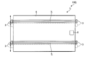
- FIG. 10 is a diagram showing the configuration of the solar cell module according to Embodiment 4.
- FIG. 11 is a diagram illustrating a configuration of a solar cell system according to a comparative example.
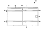
- FIG. 12 is a diagram illustrating a configuration of a solar cell module in a comparative example.
- FIG. 1 is a perspective view showing the configuration of the solar cell system 100.
- a plurality of solar cell modules 1 are installed on an installation surface (not shown) using the solar cell mount 20.
- FIG. 1 shows two columns (2 FIG. 12 is a perspective view of the solar cell modules 1-1 to 1-12) in a row extracted from the back side.
- FIG. 2 is a perspective view of each solar cell module 1 according to Embodiment 1 as viewed from the back side opposite to the light receiving surface.
- a plurality of solar cell modules 1 shown in FIG. 2 are attached to form a solar cell system.
- the introduction of solar cells has increased along with the importance of natural energy, and solar cell power generation facilities equipped with thousands of solar cell modules, called mega solar, have been created.
- the structure of a solar cell base suitable for power generation is also important.
- the solar cell base 20 having an inclination to receive sunlight efficiently can be installed anywhere with an open space with a high power generation efficiency, but as a pedestal Since the size is large, the installation cost is high, and a structure with reduced cost is required.
- Each of the solar cell base 20 and the solar cell module 1 is required to withstand a load assumed at the time of use. As specified in JIS, the most severe loads are wind pressure due to wind and load due to snow. Both are pressures applied to the main surface of the solar cell panel 6.
- the solar cell module 1 is designed so that the strength against a pressure load is secured as a single unit. In the solar cell system 100, a solar cell mount 20 that can withstand the load is installed.
- FIG. 11 shows a configuration of a solar cell system 900 according to a comparative example
- FIG. 12 shows a configuration of a solar cell module 901 in the comparative example.
- the solar cell panel 906 in which the solar cells that generate power are bonded to the glass substrate and sealed, can withstand the pressure load by attaching the frame 909 to the four sides like the window frame. It has a designed structure.
- a support frame 910 is added between the two long-side frames 909 facing each other on the inner side of the solar cell panel 906, that is, the back surface.
- a large degree of freedom was given when the solar cell panel was small, but when the solar cell panel 906 was enlarged In order to reduce the influence of the pressure load, it is becoming limited to a portion inside the end portion of the long side frame 909.
- the additional support frame 910 is mounted between the two long side frames 909 facing each other in order to maximize its cost effectiveness (for example, to shorten the length). Therefore, it is necessary to reduce the load on the long-side frame 909. Therefore, in the solar cell system 900 shown in FIG. 11, the solar cell modules 901 arranged along the short side of the solar cell panel 906 are aligned with the long side frame 909 in the direction along the back surface of the solar cell panel 906. It is attached to two longitudinal members 922 each extending in a vertical direction. In the solar cell mount 920, each vertical member 922 is supported by a base material 925 and an oblique material 924.
- the solar cell system 100 is a solar cell in which the holding member 7 is installed inside the solar cell module surface in a direction parallel to the long side of the rectangular solar cell panel 6 as shown in FIG.
- the module 1 is composed of a solar cell mount 20 in which adjacent short sides are attached to one vertical member 22.
- the holding member 7 is parallel to the long side of the solar cell panel 6 from the inside of the solar cell panel 6 when viewed from a direction perpendicular to the main surface (for example, the light receiving surface) of the solar cell panel 6. It extends so as to protrude to both short sides in the direction.
- the holding member 7 is bonded to the back surface (the main surface opposite to the light receiving surface) of the solar cell panel 6.
- the solar cell mount 20 has the vertical member (bar-shaped member) 22 to which the short side group of 1 row was attached via the holding member 7.
- the short side group in one row is a set of short sides of adjacent solar cell panels 6 arranged in a direction along the short side of the solar cell panel 6.
- Such a vertical member 22 is provided for each of a plurality of rows of short side groups.
- Each longitudinal member 22 is supported by a base member 25 and an oblique member 24.
- the solar cell modules 1-2, 1-4, 1-6, 1-8, 1-10, 1-12 arranged along the short side of the solar cell panel 6 are While being supported by the vertical members 22 on both sides, the solar cell modules are substantially attached with one vertical member 22 per solar cell module (corresponding to only one row at the end of the plurality of rows).
- the solar cell mount 20 can be obtained with 11 vertical members 22.
- the vertical members 22 are reduced, the diagonal members 24 and the base members 25 that support the vertical members 22 can also be reduced. Therefore, the number of members and the number of operations can be reduced, and the cost can be greatly reduced.
- the solar cell panel 6 is attached to the vertical member 22 at the center instead of the short side, one solar cell module 1 per one end of the plurality of rows. Since it can be attached with one vertical member, one vertical member can be further reduced as a whole, but the adjacent solar cell panels 6 are not joined to each other, so that the solar cell mount 20 supports the base material 25. Rigidity tends to be insufficient, and the base material 25 itself needs to be strengthened so that the base material 25 does not fall down, or it is necessary to perform joining with another horizontal base member.
- the adjacent solar cell panels 6 are joined by the vertical member 22 via the holding member 7, so that the rigidity of the holding member 7 causes the vertical member 22 to pass through.
- the support rigidity of the base material 25 can be reinforced, and the base material 25 can be prevented from falling.
- the solar cell system 100 includes the large-area solar cell module 1 in which the holding member 7 is installed inside the solar cell module surface in a direction parallel to the long side of the solar cell panel 6.
- the solar cell base 20 is provided so that the short sides of the adjacent solar cell panels 6 are attached to one vertical member 22 when a large number of the solar cell modules 1 are arranged. That is, when the holding member 7 is seen through from a direction perpendicular to the main surface (for example, a light receiving surface) of the solar cell panel 6, both the holding members 7 extend in the direction parallel to the long side of the solar cell panel 6 from the inside of the solar cell panel 6. It extends so as to protrude to the short side.
- the vertical member 22 is attached with a group of short sides in which a pair of short sides of adjacent solar cell panels 6 is arranged in a direction along the short side of the solar cell panel 6 via the holding member 7. Yes.
- the solar cell modules 1-2, 1-4, 1-6, 1-8, 1-10, 1-12 arranged along the short side of the solar cell panel 6 are supported by the vertical members 22 on both sides. While being supported, one solar cell module 1 is substantially attached with one vertical member 22 (corresponding to two at the very end of the plurality of rows). For this reason, the number of the vertical members 22 in the solar cell mount 20 can be significantly reduced from the conventional one using the large-area solar cell module 1, and the number of parts as a whole can be reduced. Increase in installation cost can be suppressed.
- the holding member 7 is bonded to the back surface of the solar cell panel 6 in a direction parallel to the long side.
- the holding member 7 is directly bonded to the back surface of the solar cell panel 6, but the holding member 7 may be bonded to the back surface of the solar cell panel 6 through a spacer or the like. Absent.
- the adhesive to be used is not limited, but a silicone-based adhesive is suitable due to the fact that it is used outdoors for a long time and the difference in thermal expansion coefficient between the solar cell panel 6 and the holding member 7. It is thought that there is.
- each holding member 7 is based on the position where the short side of the solar cell panel 6 is divided 1: 3: 1. It may be adhered as.
- the present inventor has analyzed the bonding position and the stress of the solar cell panel. The results are shown in FIGS. That is, the position of each holding member 7 is at a position that is, for example, 0.2 times the short side length, that is, at a position that divides the short side into 1: 3: 1.
- the analysis result (for example, the graph of FIG. 4) by the inventor has shown that the applied stress can be efficiently reduced (for example, can be minimized). This position is only a reference, and an allowable error of about 10% may be provided depending on design requirements.
- each holding member 7 is based on the position where the short side of the solar cell panel 6 is divided into 3: 7: 7: 3. It may be bonded. Also in this case, although not shown, the inventor has analyzed the bonding position and the stress of the solar cell panel. That is, the stress applied to, for example, the light receiving surface of the solar cell panel 6 can be efficiently reduced because the position of the holding member 7 is at a position obtained by dividing the short side of the solar cell panel 6 into 3: 7: 7: 3 (for example, The result of the analysis by the present inventor was shown to be the lowest possible. This position is only a reference, and an allowable error of about 10% may be provided depending on design requirements.
- the present inventor analyzed the case where the solar cell panel 906 was enlarged in the configuration of the comparative example shown in FIGS. As a result, although not shown, it has become clear that when the long side of the solar cell panel 906 is larger than 1.3 m, it is difficult to fix the solar cell panel 906 with the short side.
- the case where the solar cell panel 6 was enlarged in the configuration of the present embodiment was also analyzed. As a result, although not shown, it was confirmed that the effect of the present embodiment can be obtained even in the solar cell module 1 in which the long side of the solar cell panel 6 shown in FIG. 2 is larger than 1.3 m.
- the conventional solar cell module 901 shown in FIG. 12 using tempered glass having a thickness of 3.2 mm as a substrate when the long side of the solar cell panel 6 is 1.6 m, the surface pressure is fixed in the short side fixed state. It was revealed that when 5400 Pa was applied, the performance as a solar cell was affected.
- the solar cell panel 6 when the long side of the solar cell panel 6 is larger than 1.3 m, and particularly larger than 1.6 m, the solar cell panel 6 has been difficult to realize with the configuration of the comparative example shown in FIGS. It was confirmed that the effect of being able to be fixed at the short side was obtained. Therefore, the manufacturing cost of the solar cell panel around the area and around the power generation amount can be reduced by increasing the size.
- the effect of the present embodiment can be obtained even if the total thickness of the glass substrate in the solar cell panel 6 is 2.5 mm or less. That is, when the total thickness of the glass substrate in the solar cell panel 6 is 2.5 mm or less, the light receiving surface of the solar cell panel 6 is difficult to realize with the configuration of the comparative example shown in FIGS. It was confirmed that the effect of being able to withstand the acting surface pressure was obtained.
- the glass substrate may be a single glass substrate or a combination of two glass substrates. Therefore, thin glass can be used, the manufacturing cost of the solar cell panel can be reduced, and the solar cell panel can be reduced in weight.
- the holding member 7 is bonded to the back surface of the solar cell panel 6.
- the solar cell panel 6 has a glass substrate having a long side of 1.3 m or more, a short side of 0.9 m or more, and a total plate thickness of 2.5 mm or less. That is, even if the solar cell panel 6 is enlarged due to the rigidity of the holding member 7, it can withstand a large surface pressure acting on the light receiving surface of the solar cell panel 6, and thin glass can be used as the glass substrate.
- the panel 6 can be made larger and lighter at the same time, and the manufacturing cost of the solar cell module 1 per unit area / power generation amount of the solar cell panel 6 can be greatly reduced.
- Embodiment 1 although the solar cell mount 20 which installs the several solar cell module 1 with an inclination was demonstrated as an example, if there is a mount member equivalent to the vertical member 22, this embodiment It is clear that the concept of the form can be applied to a solar cell mount in which a plurality of solar cell modules 1 are installed without an inclination. Examples include a vertical installation stand installed on the side of a building, a stand attached to a solar tracking device, a stand built on a roof, and the like.
- the holding member 7 bonded to the back surface of the solar cell panel 6 may be a rail made by bending a plate-like metal, for example.
- a corrosion-resistant metal such as stainless steel or aluminum, a galvanized steel plate, or the like is suitable.
- the holding member 7 may have a plurality of holes in the side surface 7 a facing the long side of the solar cell panel 6.
- the hole for weight reduction is made avoiding the vicinity of the center of the back surface of the solar cell panel 6, the influence of strength reduction due to weight reduction can be reduced. Since the stress is particularly high in the vicinity of the central portion 7c, the influence of the strength reduction can be reduced by avoiding the stress.
- the right half of the lower holding member 7 in FIG. 2 will be described as an example.
- the portion on the right side from the central portion 7c of the holding member 7 is L that is half of the length when the entire length of the holding member 7 is 2L.
- the length from the central portion 7c to the boundary portion 7b of the 30% region in the vicinity of the central portion 7c is 0.3L.
- the plurality of holes 7d-1 to 7d-5 are provided in a region having a length of 0.7 L from the boundary portion 7b to the end portion 7e. That is, each of the holes 7d-1 to 7d-5 is provided at a position separated from the central portion 7c by 30% or more of the length from the central portion 7c to the end portion 7e on the side surface 7a of the holding member 7.
- This hole can serve as a handle when the solar cell module 1 is carried, and can also be used to fix a cable connecting the solar cell module 1 when installed.
- the size of each hole is desirably 5 cm or more in the wide direction.
- each hole is smaller than 5 cm in the wide direction, it becomes difficult to insert the operator's four fingers during carrying, and the convenience as a handle tends to decrease.
- the electric power extraction part 8 may be distribute
- Embodiment 2 a solar cell system 100i according to the second embodiment will be described. Below, it demonstrates focusing on a different point from Embodiment 1.
- FIG. 1 a solar cell system 100i according to the second embodiment
- the two holding members 7 are bonded to the opposing two short-side frames 909.
- the strength when holding the solar cell panel 906 can be further improved, and the solar cell panel 906 is further enlarged. Even in this case, it is possible to withstand a large surface pressure applied to the light receiving surface of the solar cell panel 906, and the manufacturing cost of the solar cell panel 906 around the area and around the power generation amount can be reduced.
- the vertical member 22 (see FIG. 1) of the solar cell mount 20 can be significantly reduced from the comparative example shown in FIG. 11 after using the large-area solar cell module 1i.
- the number of points can be reduced, and the increase in installation cost can be suppressed.
- the support frame 910 and the two long side frames 909 facing each other can be omitted while maintaining the strength at the time of holding the solar cell panel 906 equal to that of the first embodiment. In this case, the cost of the solar cell module 1i can be reduced.
- Embodiment 3 a solar cell system 100j according to the third embodiment will be described. Below, it demonstrates focusing on a different point from Embodiment 1.
- FIG. 1 A solar cell system 100j according to the third embodiment will be described. Below, it demonstrates focusing on a different point from Embodiment 1.
- each solar cell module 1j is different from that of the first embodiment. That is, in each solar cell module 1j, the plurality of holding members 7j are shifted from the reference position indicated by the alternate long and short dash line in the same direction (for example, upward in FIG. 7) by approximately half the member width. It is fixed to the solar cell panel 6.
- the reference position indicated by the alternate long and short dash line is, for example, a position obtained by dividing the short side of the solar cell panel 6 into 1: 3: 1.
- the stress applied to, for example, the light receiving surface of the solar cell panel can be efficiently reduced (for example, can be minimized) by being at a position divided by 1: 3: 1.
- the stress applied to, for example, the light receiving surface of the solar cell panel can be efficiently reduced by being at a position divided into 3: 7: 7: 3.
- the solar cell modules 1j-1 and 1j-2 whose short sides are adjacent to each other are reversed so that the holding members 7j are staggered between the two (see FIG. 6).
- 7 see attachment point 3 of adjacent solar cell modules 1j indicated by a broken line in FIG. 7
- the solar cell panels 6 of the plurality of solar cell modules 1j-1 to 1j-12 can be aligned and attached. Thereby, the solar cell system 100j with a good external appearance can be made.
- FIG. 8 shows a schematic diagram when the back surfaces of the solar cell panels 6 of the solar cell module 1j of the third embodiment are faced to each other.
- the holding member 7j is fixed to the back surface of the solar cell panel 6 by shifting approximately half of the member width in parallel in the same direction from the reference position, the back surfaces of the solar cell panel 6 face each other. And can be accommodated so as to engage the convex portions of the holding member 7j. Thereby, the area at the time of storage does not change, and the height can be halved, and the transportability can be improved.
- the holding member 7j may be fixed to the solar cell panel 6 at a position shifted from the reference position indicated by the alternate long and short dash line in the same direction (for example, upward in FIG. 7) by half or more of the member width. . Also in this case, it can be stored so that the back surfaces of the solar cell panel 6 face each other so as to engage the convex portion of the holding member 7j, the area at the time of storage does not change, and the height can be approximately halved. Can raise the sex.
- Embodiment 4 FIG. Next, a solar cell system 100k according to the fourth embodiment will be described. Below, it demonstrates focusing on a different point from Embodiment 3. FIG.
- each solar cell module 1k is different from that of the third embodiment, as shown in FIG. That is, in each solar cell module 1k, the plurality of holding members 7k are in the same direction so that the positions on both short sides of the solar cell panel 6 are shifted by approximately half of the member width from the reference position indicated by the alternate long and short dash line. It is fixed to the solar cell panel 6 at a position rotated (for example, clockwise in FIG. 10).
- the reference position indicated by the alternate long and short dash line is, for example, a position obtained by dividing the short side of the solar cell panel 6 into 1: 3: 1.
- the stress applied to, for example, the light receiving surface of the solar cell panel can be efficiently reduced (for example, can be minimized) by being at a position divided by 1: 3: 1.
- the stress applied to, for example, the light receiving surface of the solar cell panel can be efficiently reduced by being at a position divided into 3: 7: 7: 3.
- the holding members 7k are staggered between the solar cell modules 1k-1 and 1k-2 whose short sides are adjacent to each other in the same direction (
- the solar cell panels 6 of the plurality of solar cell modules 1k can be aligned and attached by referring to the attachment points 3 of the adjacent solar cell modules 1k indicated by broken lines in FIG. Thereby, the solar cell system 100k with a good external appearance can be made.
- the power extraction unit 8 and the like are asymmetrical.
- the installed solar cell module 1k can also be installed.
- the holding member 7k is moved in the same direction (for example, clockwise direction in FIG. 10) so that the positions on both short sides of the solar cell panel 6 are shifted by approximately half of the member width from the reference position indicated by the alternate long and short dash line. You may fix to the solar cell panel 6 in the position rotated to (3). Also in this case, for example, the solar cell modules 1k-1 and 1k-2 whose short sides are adjacent to each other have the same direction, and the holding members 7k are staggered between them (adjacent ones indicated by broken lines in FIG. 10). By attaching the solar cell module 1k to the attachment point 3), the solar cell panels 6 of the plurality of solar cell modules 1k can be aligned and attached. Thereby, the solar cell system 100k with a good external appearance can be made.
- the solar cell system according to the present invention is useful for installing a plurality of solar cell modules.
Abstract
Description
実施の形態1にかかる太陽電池システム100について図1を用いて説明する。図1は、太陽電池システム100の構成を示す斜視図である。
次に、実施の形態2にかかる太陽電池システム100iについて説明する。以下では、実施の形態1と異なる点を中心に説明する。
次に、実施の形態3にかかる太陽電池システム100jについて説明する。以下では、実施の形態1と異なる点を中心に説明する。
次に、実施の形態4にかかる太陽電池システム100kについて説明する。以下では、実施の形態3と異なる点を中心に説明する。
3、903 接続するポイント
6 太陽電池パネル
7、7j、7k 保持部材
7a 側面
7b 境界部分
7c 中央部
7d-1~7d-5 穴
7e 端部
8 電力取出部
20、920 太陽電池架台
22、922 縦材
24、924 斜め材
25、925 基礎材
100、100i、100j、100k、900 太陽電池システム
909 フレーム
910 支持フレーム
Claims (16)
- 2次元的に配列された複数の太陽電池モジュールと、
前記複数の太陽電池モジュールを支持する架台と、
を備え、
前記複数の太陽電池モジュールのそれぞれは、
矩形状の太陽電池パネルと、
前記太陽電池パネルの主面に垂直な方向から透視した場合に前記太陽電池パネルの内側から前記太陽電池パネルの長辺と平行な方向に両短辺側までそれぞれ延び、前記太陽電池パネルを保持する保持部材と、
を有し、
前記架台は、隣り合う前記太陽電池パネルの短辺の組が短辺に沿った方向に並んだ1列の短辺群が前記保持部材を介して取り付けられた棒状部材を複数有し、
前記保持部材は、前記太陽電池パネルの裏面に接着されており、
前記太陽電池パネルの長辺は、1.3m以上であり、
前記太陽電池パネルの短辺は、0.9m以上であり、
前記太陽電池パネルは、総板厚が2.5mm以下のガラス基板を有する
ことを特徴とする太陽電池システム。 - 前記複数の太陽電池モジュールのそれぞれは、前記保持部材を複数本有し、
前記保持部材は、2本の場合に前記太陽電池パネルの短辺を1:3:1に分割した位置を基準として前記太陽電池パネルの裏面に接着され、3本の場合に前記太陽電池パネルの短辺を3:7:7:3に分割した位置を基準として前記太陽電池パネルの裏面に接着されている
ことを特徴とする請求項1に記載の太陽電池システム。 - 前記複数の太陽電池モジュールのそれぞれは、前記保持部材を複数本有し、
複数本の前記保持部材は、基準となる位置より、同じ方向に部材幅の半分以上シフトさせた位置において前記太陽電池パネルに固定されている
ことを特徴とする請求項1に記載の太陽電池システム。 - 前記複数の太陽電池モジュールのそれぞれは、前記保持部材を複数本有し、
前記保持部材は、2本の場合に前記太陽電池パネルの短辺を1:3:1に分割した位置を基準として前記太陽電池パネルの裏面に接着され、3本の場合に前記太陽電池パネルの短辺を3:7:7:3に分割した位置を基準として前記太陽電池パネルの裏面に接着されており、
複数本の前記保持部材は、基準となる位置より、同じ方向に部材幅の半分以上シフトさせた位置において前記太陽電池パネルに固定されている
ことを特徴とする請求項1に記載の太陽電池システム。 - 前記複数の太陽電池モジュールのそれぞれは、前記保持部材を複数本有し、
複数本の前記保持部材は、基準となる位置より、前記太陽電池パネルの両短辺における位置が部材幅の半分以上シフトするように同じ方向に回転させた位置において前記太陽電池パネルに固定されている
ことを特徴とする請求項1に記載の太陽電池システム。 - 前記複数の太陽電池モジュールのそれぞれは、前記保持部材を複数本有し、
前記保持部材は、2本の場合に前記太陽電池パネルの短辺を1:3:1に分割した位置を基準として前記太陽電池パネルの裏面に接着され、3本の場合に前記太陽電池パネルの短辺を3:7:7:3に分割した位置を基準として前記太陽電池パネルの裏面に接着されており、
複数本の前記保持部材は、基準となる位置より、前記太陽電池パネルの両短辺における位置が部材幅の半分以上シフトするように同じ方向に回転させた位置において前記太陽電池パネルに固定されている
ことを特徴とする請求項1に記載の太陽電池システム。 - 前記保持部材は、前記太陽電池パネルの長辺側に向いた側面に穴を有する
ことを特徴とする請求項1に記載の太陽電池システム。 - 前記穴は、前記保持部材の前記側面における中央部から端部までの長さの30%以上前記中央部から離れた位置に設けられている
ことを特徴とする請求項1に記載の太陽電池システム。 - 矩形状の太陽電池パネルと、
前記太陽電池パネルの主面に垂直な方向から透視した場合に前記太陽電池パネルの内側から前記太陽電池パネルの長辺と平行な方向に両短辺側までそれぞれ延び、前記太陽電池パネルを保持する保持部材と、
を備え、
前記太陽電池パネルの長辺は、1.3m以上であり、
前記太陽電池パネルの短辺は、0.9m以上であり、
前記太陽電池パネルは、総板厚が2.5mm以下のガラス基板を有する
ことを特徴とする太陽電池モジュール。 - 前記太陽電池モジュールは、前記保持部材を複数本備え、
前記保持部材は、2本の場合に前記太陽電池パネルの短辺を1:3:1に分割した位置を基準として前記太陽電池パネルの裏面に接着され、3本の場合に前記太陽電池パネルの短辺を3:7:7:3に分割した位置を基準として前記太陽電池パネルの裏面に接着されている
ことを特徴とする請求項9に記載の太陽電池モジュール。 - 前記太陽電池モジュールは、前記保持部材を複数本備え、
複数本の前記保持部材は、基準となる位置より、同じ方向に部材幅の半分以上シフトさせた位置において前記太陽電池パネルに固定されている
ことを特徴とする請求項9に記載の太陽電池モジュール。 - 前記太陽電池モジュールは、前記保持部材を複数本備え、
前記保持部材は、2本の場合に前記太陽電池パネルの短辺を1:3:1に分割した位置を基準として前記太陽電池パネルの裏面に接着され、3本の場合に前記太陽電池パネルの短辺を3:7:7:3に分割した位置を基準として前記太陽電池パネルの裏面に接着されており、
複数本の前記保持部材は、基準となる位置より、同じ方向に部材幅の半分以上シフトさせた位置において前記太陽電池パネルに固定されている
ことを特徴とする請求項9に記載の太陽電池モジュール。 - 前記太陽電池モジュールは、前記保持部材を複数本備え、
複数本の前記保持部材は、基準となる位置より、前記太陽電池パネルの両短辺における位置が部材幅の半分以上シフトするように同じ方向に回転させた位置において前記太陽電池パネルに固定されている
ことを特徴とする請求項9に記載の太陽電池モジュール。 - 前記複数の太陽電池モジュールのそれぞれは、前記保持部材を複数本有し、
前記保持部材は、2本の場合に前記太陽電池パネルの短辺を1:3:1に分割した位置を基準として前記太陽電池パネルの裏面に接着され、3本の場合に前記太陽電池パネルの短辺を3:7:7:3に分割した位置を基準として前記太陽電池パネルの裏面に接着されており、
複数本の前記保持部材は、基準となる位置より、前記太陽電池パネルの両短辺における位置が部材幅の半分以上シフトするように同じ方向に回転させた位置において前記太陽電池パネルに固定されている
ことを特徴とする請求項9に記載の太陽電池モジュール。 - 前記保持部材は、前記太陽電池パネルの長辺側に向いた側面に穴を有する
ことを特徴とする請求項9に記載の太陽電池モジュール。 - 前記穴は、前記保持部材の前記側面における中央部から端部までの長さの30%以上前記中央部から離れた位置に設けられている
ことを特徴とする請求項9に記載の太陽電池モジュール。
Priority Applications (4)
| Application Number | Priority Date | Filing Date | Title |
|---|---|---|---|
| CN201280021854.7A CN103548255B (zh) | 2011-05-06 | 2012-04-20 | 太阳能电池系统及太阳能电池模块 |
| DE112012001993.8T DE112012001993T8 (de) | 2011-05-06 | 2012-04-20 | Solarbatteriesystem und Solarbatteriemodul |
| US14/009,390 US20140014165A1 (en) | 2011-05-06 | 2012-04-20 | Solar battery system and solar battery module |
| JP2013513971A JP5377798B2 (ja) | 2011-05-06 | 2012-04-20 | 太陽電池システム、及び太陽電池モジュール |
Applications Claiming Priority (2)
| Application Number | Priority Date | Filing Date | Title |
|---|---|---|---|
| JP2011103624 | 2011-05-06 | ||
| JP2011-103624 | 2011-05-06 |
Publications (1)
| Publication Number | Publication Date |
|---|---|
| WO2012153621A1 true WO2012153621A1 (ja) | 2012-11-15 |
Family
ID=47139107
Family Applications (1)
| Application Number | Title | Priority Date | Filing Date |
|---|---|---|---|
| PCT/JP2012/060755 WO2012153621A1 (ja) | 2011-05-06 | 2012-04-20 | 太陽電池システム、及び太陽電池モジュール |
Country Status (5)
| Country | Link |
|---|---|
| US (1) | US20140014165A1 (ja) |
| JP (2) | JP5377798B2 (ja) |
| CN (1) | CN103548255B (ja) |
| DE (1) | DE112012001993T8 (ja) |
| WO (1) | WO2012153621A1 (ja) |
Cited By (1)
| Publication number | Priority date | Publication date | Assignee | Title |
|---|---|---|---|---|
| JP2014095261A (ja) * | 2012-11-12 | 2014-05-22 | Mitsubishi Electric Corp | 太陽電池モジュールの固定具及びこの固定具を用いた太陽光発電システム |
Families Citing this family (9)
| Publication number | Priority date | Publication date | Assignee | Title |
|---|---|---|---|---|
| JP5746957B2 (ja) * | 2011-12-02 | 2015-07-08 | 株式会社エクソル | 太陽電池モジュールの架台支持構造 |
| CN106170917A (zh) * | 2014-01-07 | 2016-11-30 | 阿纳尔太阳能有限责任公司 | 高度可调节并且可适配的外部面板垛架系统 |
| NL1041128B1 (en) * | 2014-12-22 | 2016-10-11 | Ing Petrus Paulus Carolus Maria Stassen | A roof or wall covering system, a panel and method for installing panels. |
| JP6269631B2 (ja) * | 2015-09-29 | 2018-01-31 | イビデンエンジニアリング株式会社 | 太陽光発電ユニット |
| US9923513B2 (en) * | 2016-05-13 | 2018-03-20 | Boson Robotics Ltd. | Cleaning mechanism having water spray function and photovoltaic panel cleaning equipment having same |
| US10615738B2 (en) * | 2018-04-10 | 2020-04-07 | Barry Sgarrella | Photovoltaic solar array support structure |
| AT521487B1 (de) * | 2018-10-17 | 2020-02-15 | Wakonig Martin | Vorrichtung zur vertikalen Anbringung an einer Wand |
| US11394342B2 (en) * | 2019-08-23 | 2022-07-19 | Workshops for Warriors | Modular solar panel assembly |
| RU202039U1 (ru) * | 2020-07-03 | 2021-01-28 | Федеральное государственное бюджетное образовательное учреждение высшего образования "Московский государственный технологический университет "СТАНКИН" (ФГБОУ ВО "МГТУ "СТАНКИН") | Солнечный трекер |
Citations (3)
| Publication number | Priority date | Publication date | Assignee | Title |
|---|---|---|---|---|
| WO2006121013A1 (ja) * | 2005-05-11 | 2006-11-16 | Kaneka Corporation | 太陽電池モジュール、及び太陽電池設置面 |
| JP2008117926A (ja) * | 2006-11-02 | 2008-05-22 | Mitsui Chemicals Inc | 太陽電池モジュールの製造方法及び製造装置 |
| JP2011222930A (ja) * | 2010-03-25 | 2011-11-04 | Sharp Corp | 太陽電池モジュールの取付構造 |
Family Cites Families (9)
| Publication number | Priority date | Publication date | Assignee | Title |
|---|---|---|---|---|
| BR9007327A (pt) * | 1989-04-25 | 1992-04-28 | Glasstech Inc | Conjunto de suporte para montagem de um jogo de paineis |
| US6201181B1 (en) * | 1998-12-08 | 2001-03-13 | Ase Americas, Inc. | Portable solar module cart |
| US7012188B2 (en) * | 2000-04-04 | 2006-03-14 | Peter Stuart Erling | Framing system for solar panels |
| JP2003343058A (ja) * | 2003-06-16 | 2003-12-03 | Sharp Corp | 太陽電池モジュールの取付構造 |
| CN200959496Y (zh) * | 2006-07-18 | 2007-10-10 | 沈彬 | 室内多孔托线架 |
| US20090114261A1 (en) * | 2007-08-29 | 2009-05-07 | Robert Stancel | Edge Mountable Electrical Connection Assembly |
| FR2922365B1 (fr) * | 2007-10-16 | 2009-12-18 | Avancis Gmbh & Co Kg | Perfectionnements apportes a des elements capables de collecter de la lumiere. |
| WO2009086241A2 (en) * | 2007-12-21 | 2009-07-09 | E. I. Du Pont De Nemours And Company | Photovoltaic array, framework, and methods of installation and use |
| US20090205703A1 (en) * | 2008-02-14 | 2009-08-20 | Applied Materials, Inc. | Apparatus and method of mounting and supporting a solar panel |
-
2012
- 2012-04-20 WO PCT/JP2012/060755 patent/WO2012153621A1/ja active Application Filing
- 2012-04-20 JP JP2013513971A patent/JP5377798B2/ja not_active Expired - Fee Related
- 2012-04-20 US US14/009,390 patent/US20140014165A1/en not_active Abandoned
- 2012-04-20 CN CN201280021854.7A patent/CN103548255B/zh not_active Expired - Fee Related
- 2012-04-20 DE DE112012001993.8T patent/DE112012001993T8/de not_active Withdrawn - After Issue
-
2013
- 2013-09-12 JP JP2013189381A patent/JP5847143B2/ja not_active Expired - Fee Related
Patent Citations (3)
| Publication number | Priority date | Publication date | Assignee | Title |
|---|---|---|---|---|
| WO2006121013A1 (ja) * | 2005-05-11 | 2006-11-16 | Kaneka Corporation | 太陽電池モジュール、及び太陽電池設置面 |
| JP2008117926A (ja) * | 2006-11-02 | 2008-05-22 | Mitsui Chemicals Inc | 太陽電池モジュールの製造方法及び製造装置 |
| JP2011222930A (ja) * | 2010-03-25 | 2011-11-04 | Sharp Corp | 太陽電池モジュールの取付構造 |
Cited By (1)
| Publication number | Priority date | Publication date | Assignee | Title |
|---|---|---|---|---|
| JP2014095261A (ja) * | 2012-11-12 | 2014-05-22 | Mitsubishi Electric Corp | 太陽電池モジュールの固定具及びこの固定具を用いた太陽光発電システム |
Also Published As
| Publication number | Publication date |
|---|---|
| JPWO2012153621A1 (ja) | 2014-07-31 |
| CN103548255B (zh) | 2016-11-23 |
| JP5847143B2 (ja) | 2016-01-20 |
| JP5377798B2 (ja) | 2013-12-25 |
| DE112012001993T8 (de) | 2014-06-26 |
| DE112012001993T5 (de) | 2014-03-27 |
| CN103548255A (zh) | 2014-01-29 |
| JP2014025339A (ja) | 2014-02-06 |
| US20140014165A1 (en) | 2014-01-16 |
Similar Documents
| Publication | Publication Date | Title |
|---|---|---|
| JP5377798B2 (ja) | 太陽電池システム、及び太陽電池モジュール | |
| US20130112247A1 (en) | Frame for solar panels | |
| US9951972B2 (en) | Fixing metal bracket and solar battery system | |
| JP2010027979A (ja) | 太陽光発電システムおよびその製造方法 | |
| JP5365937B2 (ja) | 太陽電池パネルの取付装置 | |
| JP5213977B2 (ja) | 太陽電池モジュールの架台、その施工方法、及びそれを備えた太陽光発電システム | |
| JP2018046204A (ja) | 太陽光発電ユニットと太陽電池モジュールの補修方法 | |
| JP2014009569A (ja) | 太陽電池モジュール設置用架台 | |
| JP2013147831A (ja) | 太陽電池モジュール、太陽電池モジュールの支持構造、太陽電池モジュールの設置方法、及び太陽光発電システム | |
| JP6432958B1 (ja) | 太陽光発電パネル用取付具、及び太陽光発電パネルの取付構造 | |
| EP2706579A1 (en) | Support structure for photovoltaic module mounting and methods of its use | |
| JP2016005316A (ja) | 太陽光発電モジュール支持金具及び支持方法 | |
| JP6877929B2 (ja) | 太陽光発電ユニット及び太陽電池モジュールの装着方法 | |
| JP2015211622A (ja) | 太陽光発電モジュールの支持架台の構造 | |
| JP6449006B2 (ja) | 屋根構造 | |
| KR20170012637A (ko) | 태양전지패널의 처짐보강부재 | |
| JP3204348U (ja) | 太陽光発電パネル架台 | |
| JP3179155U (ja) | 太陽電池モジュールの固定構造 | |
| JP6085822B2 (ja) | パネル取付構造 | |
| JP6051030B2 (ja) | 太陽電池パネルの敷設構造 | |
| JP2014005668A (ja) | 太陽電池モジュールの取り付け構造 | |
| JP2013129994A (ja) | 太陽光発電外装構造及びその施工方法 | |
| JP7049136B2 (ja) | 太陽電池モジュール組立体 | |
| JP2011226122A (ja) | 太陽電池アレイの施工方法 | |
| JP2013231308A (ja) | 太陽電池モジュール |
Legal Events
| Date | Code | Title | Description |
|---|---|---|---|
| 121 | Ep: the epo has been informed by wipo that ep was designated in this application |
Ref document number: 12781561 Country of ref document: EP Kind code of ref document: A1 |
|
| ENP | Entry into the national phase |
Ref document number: 2013513971 Country of ref document: JP Kind code of ref document: A |
|
| WWE | Wipo information: entry into national phase |
Ref document number: 14009390 Country of ref document: US |
|
| WWE | Wipo information: entry into national phase |
Ref document number: 1120120019938 Country of ref document: DE Ref document number: 112012001993 Country of ref document: DE |
|
| 122 | Ep: pct application non-entry in european phase |
Ref document number: 12781561 Country of ref document: EP Kind code of ref document: A1 |