WO2012147675A1 - ステント - Google Patents
ステント Download PDFInfo
- Publication number
- WO2012147675A1 WO2012147675A1 PCT/JP2012/060825 JP2012060825W WO2012147675A1 WO 2012147675 A1 WO2012147675 A1 WO 2012147675A1 JP 2012060825 W JP2012060825 W JP 2012060825W WO 2012147675 A1 WO2012147675 A1 WO 2012147675A1
- Authority
- WO
- WIPO (PCT)
- Prior art keywords
- stent
- stent body
- bulging portion
- axial direction
- slope
- Prior art date
Links
Images


Classifications
-
- A—HUMAN NECESSITIES
- A61—MEDICAL OR VETERINARY SCIENCE; HYGIENE
- A61F—FILTERS IMPLANTABLE INTO BLOOD VESSELS; PROSTHESES; DEVICES PROVIDING PATENCY TO, OR PREVENTING COLLAPSING OF, TUBULAR STRUCTURES OF THE BODY, e.g. STENTS; ORTHOPAEDIC, NURSING OR CONTRACEPTIVE DEVICES; FOMENTATION; TREATMENT OR PROTECTION OF EYES OR EARS; BANDAGES, DRESSINGS OR ABSORBENT PADS; FIRST-AID KITS
- A61F2/00—Filters implantable into blood vessels; Prostheses, i.e. artificial substitutes or replacements for parts of the body; Appliances for connecting them with the body; Devices providing patency to, or preventing collapsing of, tubular structures of the body, e.g. stents
- A61F2/02—Prostheses implantable into the body
- A61F2/04—Hollow or tubular parts of organs, e.g. bladders, tracheae, bronchi or bile ducts
- A61F2/06—Blood vessels
- A61F2/07—Stent-grafts
-
- A—HUMAN NECESSITIES
- A61—MEDICAL OR VETERINARY SCIENCE; HYGIENE
- A61F—FILTERS IMPLANTABLE INTO BLOOD VESSELS; PROSTHESES; DEVICES PROVIDING PATENCY TO, OR PREVENTING COLLAPSING OF, TUBULAR STRUCTURES OF THE BODY, e.g. STENTS; ORTHOPAEDIC, NURSING OR CONTRACEPTIVE DEVICES; FOMENTATION; TREATMENT OR PROTECTION OF EYES OR EARS; BANDAGES, DRESSINGS OR ABSORBENT PADS; FIRST-AID KITS
- A61F2/00—Filters implantable into blood vessels; Prostheses, i.e. artificial substitutes or replacements for parts of the body; Appliances for connecting them with the body; Devices providing patency to, or preventing collapsing of, tubular structures of the body, e.g. stents
- A61F2/82—Devices providing patency to, or preventing collapsing of, tubular structures of the body, e.g. stents
- A61F2/86—Stents in a form characterised by the wire-like elements; Stents in the form characterised by a net-like or mesh-like structure
- A61F2/90—Stents in a form characterised by the wire-like elements; Stents in the form characterised by a net-like or mesh-like structure characterised by a net-like or mesh-like structure
- A61F2/91—Stents in a form characterised by the wire-like elements; Stents in the form characterised by a net-like or mesh-like structure characterised by a net-like or mesh-like structure made from perforated sheet material or tubes, e.g. perforated by laser cuts or etched holes
- A61F2/915—Stents in a form characterised by the wire-like elements; Stents in the form characterised by a net-like or mesh-like structure characterised by a net-like or mesh-like structure made from perforated sheet material or tubes, e.g. perforated by laser cuts or etched holes with bands having a meander structure, adjacent bands being connected to each other
-
- A—HUMAN NECESSITIES
- A61—MEDICAL OR VETERINARY SCIENCE; HYGIENE
- A61L—METHODS OR APPARATUS FOR STERILISING MATERIALS OR OBJECTS IN GENERAL; DISINFECTION, STERILISATION OR DEODORISATION OF AIR; CHEMICAL ASPECTS OF BANDAGES, DRESSINGS, ABSORBENT PADS OR SURGICAL ARTICLES; MATERIALS FOR BANDAGES, DRESSINGS, ABSORBENT PADS OR SURGICAL ARTICLES
- A61L31/00—Materials for other surgical articles, e.g. stents, stent-grafts, shunts, surgical drapes, guide wires, materials for adhesion prevention, occluding devices, surgical gloves, tissue fixation devices
- A61L31/02—Inorganic materials
- A61L31/022—Metals or alloys
-
- A—HUMAN NECESSITIES
- A61—MEDICAL OR VETERINARY SCIENCE; HYGIENE
- A61F—FILTERS IMPLANTABLE INTO BLOOD VESSELS; PROSTHESES; DEVICES PROVIDING PATENCY TO, OR PREVENTING COLLAPSING OF, TUBULAR STRUCTURES OF THE BODY, e.g. STENTS; ORTHOPAEDIC, NURSING OR CONTRACEPTIVE DEVICES; FOMENTATION; TREATMENT OR PROTECTION OF EYES OR EARS; BANDAGES, DRESSINGS OR ABSORBENT PADS; FIRST-AID KITS
- A61F2/00—Filters implantable into blood vessels; Prostheses, i.e. artificial substitutes or replacements for parts of the body; Appliances for connecting them with the body; Devices providing patency to, or preventing collapsing of, tubular structures of the body, e.g. stents
- A61F2/82—Devices providing patency to, or preventing collapsing of, tubular structures of the body, e.g. stents
- A61F2/848—Devices providing patency to, or preventing collapsing of, tubular structures of the body, e.g. stents having means for fixation to the vessel wall, e.g. barbs
-
- A—HUMAN NECESSITIES
- A61—MEDICAL OR VETERINARY SCIENCE; HYGIENE
- A61F—FILTERS IMPLANTABLE INTO BLOOD VESSELS; PROSTHESES; DEVICES PROVIDING PATENCY TO, OR PREVENTING COLLAPSING OF, TUBULAR STRUCTURES OF THE BODY, e.g. STENTS; ORTHOPAEDIC, NURSING OR CONTRACEPTIVE DEVICES; FOMENTATION; TREATMENT OR PROTECTION OF EYES OR EARS; BANDAGES, DRESSINGS OR ABSORBENT PADS; FIRST-AID KITS
- A61F2/00—Filters implantable into blood vessels; Prostheses, i.e. artificial substitutes or replacements for parts of the body; Appliances for connecting them with the body; Devices providing patency to, or preventing collapsing of, tubular structures of the body, e.g. stents
- A61F2/0077—Special surfaces of prostheses, e.g. for improving ingrowth
- A61F2002/009—Special surfaces of prostheses, e.g. for improving ingrowth for hindering or preventing attachment of biological tissue
-
- A—HUMAN NECESSITIES
- A61—MEDICAL OR VETERINARY SCIENCE; HYGIENE
- A61F—FILTERS IMPLANTABLE INTO BLOOD VESSELS; PROSTHESES; DEVICES PROVIDING PATENCY TO, OR PREVENTING COLLAPSING OF, TUBULAR STRUCTURES OF THE BODY, e.g. STENTS; ORTHOPAEDIC, NURSING OR CONTRACEPTIVE DEVICES; FOMENTATION; TREATMENT OR PROTECTION OF EYES OR EARS; BANDAGES, DRESSINGS OR ABSORBENT PADS; FIRST-AID KITS
- A61F2/00—Filters implantable into blood vessels; Prostheses, i.e. artificial substitutes or replacements for parts of the body; Appliances for connecting them with the body; Devices providing patency to, or preventing collapsing of, tubular structures of the body, e.g. stents
- A61F2/02—Prostheses implantable into the body
- A61F2/04—Hollow or tubular parts of organs, e.g. bladders, tracheae, bronchi or bile ducts
- A61F2/06—Blood vessels
- A61F2/07—Stent-grafts
- A61F2002/072—Encapsulated stents, e.g. wire or whole stent embedded in lining
-
- A—HUMAN NECESSITIES
- A61—MEDICAL OR VETERINARY SCIENCE; HYGIENE
- A61F—FILTERS IMPLANTABLE INTO BLOOD VESSELS; PROSTHESES; DEVICES PROVIDING PATENCY TO, OR PREVENTING COLLAPSING OF, TUBULAR STRUCTURES OF THE BODY, e.g. STENTS; ORTHOPAEDIC, NURSING OR CONTRACEPTIVE DEVICES; FOMENTATION; TREATMENT OR PROTECTION OF EYES OR EARS; BANDAGES, DRESSINGS OR ABSORBENT PADS; FIRST-AID KITS
- A61F2/00—Filters implantable into blood vessels; Prostheses, i.e. artificial substitutes or replacements for parts of the body; Appliances for connecting them with the body; Devices providing patency to, or preventing collapsing of, tubular structures of the body, e.g. stents
- A61F2/82—Devices providing patency to, or preventing collapsing of, tubular structures of the body, e.g. stents
- A61F2/86—Stents in a form characterised by the wire-like elements; Stents in the form characterised by a net-like or mesh-like structure
- A61F2/90—Stents in a form characterised by the wire-like elements; Stents in the form characterised by a net-like or mesh-like structure characterised by a net-like or mesh-like structure
- A61F2/91—Stents in a form characterised by the wire-like elements; Stents in the form characterised by a net-like or mesh-like structure characterised by a net-like or mesh-like structure made from perforated sheet material or tubes, e.g. perforated by laser cuts or etched holes
- A61F2/915—Stents in a form characterised by the wire-like elements; Stents in the form characterised by a net-like or mesh-like structure characterised by a net-like or mesh-like structure made from perforated sheet material or tubes, e.g. perforated by laser cuts or etched holes with bands having a meander structure, adjacent bands being connected to each other
- A61F2002/9155—Adjacent bands being connected to each other
- A61F2002/91558—Adjacent bands being connected to each other connected peak to peak
-
- A—HUMAN NECESSITIES
- A61—MEDICAL OR VETERINARY SCIENCE; HYGIENE
- A61F—FILTERS IMPLANTABLE INTO BLOOD VESSELS; PROSTHESES; DEVICES PROVIDING PATENCY TO, OR PREVENTING COLLAPSING OF, TUBULAR STRUCTURES OF THE BODY, e.g. STENTS; ORTHOPAEDIC, NURSING OR CONTRACEPTIVE DEVICES; FOMENTATION; TREATMENT OR PROTECTION OF EYES OR EARS; BANDAGES, DRESSINGS OR ABSORBENT PADS; FIRST-AID KITS
- A61F2210/00—Particular material properties of prostheses classified in groups A61F2/00 - A61F2/26 or A61F2/82 or A61F9/00 or A61F11/00 or subgroups thereof
- A61F2210/0004—Particular material properties of prostheses classified in groups A61F2/00 - A61F2/26 or A61F2/82 or A61F9/00 or A61F11/00 or subgroups thereof bioabsorbable
-
- A—HUMAN NECESSITIES
- A61—MEDICAL OR VETERINARY SCIENCE; HYGIENE
- A61F—FILTERS IMPLANTABLE INTO BLOOD VESSELS; PROSTHESES; DEVICES PROVIDING PATENCY TO, OR PREVENTING COLLAPSING OF, TUBULAR STRUCTURES OF THE BODY, e.g. STENTS; ORTHOPAEDIC, NURSING OR CONTRACEPTIVE DEVICES; FOMENTATION; TREATMENT OR PROTECTION OF EYES OR EARS; BANDAGES, DRESSINGS OR ABSORBENT PADS; FIRST-AID KITS
- A61F2230/00—Geometry of prostheses classified in groups A61F2/00 - A61F2/26 or A61F2/82 or A61F9/00 or A61F11/00 or subgroups thereof
- A61F2230/0002—Two-dimensional shapes, e.g. cross-sections
- A61F2230/0028—Shapes in the form of latin or greek characters
- A61F2230/0054—V-shaped
-
- A—HUMAN NECESSITIES
- A61—MEDICAL OR VETERINARY SCIENCE; HYGIENE
- A61F—FILTERS IMPLANTABLE INTO BLOOD VESSELS; PROSTHESES; DEVICES PROVIDING PATENCY TO, OR PREVENTING COLLAPSING OF, TUBULAR STRUCTURES OF THE BODY, e.g. STENTS; ORTHOPAEDIC, NURSING OR CONTRACEPTIVE DEVICES; FOMENTATION; TREATMENT OR PROTECTION OF EYES OR EARS; BANDAGES, DRESSINGS OR ABSORBENT PADS; FIRST-AID KITS
- A61F2250/00—Special features of prostheses classified in groups A61F2/00 - A61F2/26 or A61F2/82 or A61F9/00 or A61F11/00 or subgroups thereof
- A61F2250/0058—Additional features; Implant or prostheses properties not otherwise provided for
- A61F2250/0059—Additional features; Implant or prostheses properties not otherwise provided for temporary
Definitions
- the present invention relates to a stent for preventing stenosis or occlusion of a tubular organ, rupture of an aneurysm, etc. by being placed in a tubular organ such as a blood vessel, a ureter, a bile duct, or a trachea.
- stents have been placed and expanded at stenosis or occlusions in human tubular organs such as blood vessels, ureters, bile ducts, and trachea. Treatment methods using stents such as prevention and the like have been performed.
- This type of stent for example, is accommodated in a reduced diameter inside a catheter, sheath, etc., and is transferred to a predetermined position of the tubular organ in that state, and then pushed out with a pusher or the like, thereby closely contacting the inner wall of the tubular organ. Are to be detained.
- the stent placed in the tubular organ in this way may have its lumen blocked by body fluid such as bile. In this case, it is necessary to remove the stent from the tubular organ and place a new stent. There is also a desire to remove the stent from the tubular organ when treatment is complete.
- a stent placed in a tubular organ can be taken out, and is composed of a hollow cylindrical body having a large number of rhombus spaces knitted so as to cross an alloy wire for stent production.
- a hollow cylindrical body having a large number of rhombus spaces knitted so as to intersect with each other a main body stent that is inserted into the inside of the body and expands a duct, and a separate biodegradable polymer wire made of a biodegradable polymer
- a biodegradable stent having a bulging portion projecting in a bulging shape at the center thereof, wherein the biodegradable stent is located on the outer surface of the main stent, and is disposed at both ends of the biodegradable stent.
- a biodegradable dual structure stent is described that is configured with either end connected to a main stent. Moreover, the said bulging part has comprised the shape swelled cyclically
- biodegradable stents made of biodegradable polymers are gradually dissolved by body fluids. Therefore, since the biodegradable stent is not melted, the main body stent arranged on the inner side can be taken out from the tubular organ.
- an object of the present invention is to provide a stent that can be accurately placed over a long period of time without being displaced at a predetermined position of the tubular organ and can be smoothly taken out from the tubular organ at a desired time.
- the stent of the present invention is placed in a tubular organ, and is made of a metal stent body, and a resin cover member covering at least a part of the outer periphery of the stent body.
- a bulging portion that is provided on a portion of the outer periphery of the stent body that is covered with the cover member and that restrains the movement of the stent in close contact with the inner wall of the tubular organ. It has a predetermined width and a predetermined length in the axial direction, and has a shape that protrudes smoothly so as to gradually rise and gradually lower.
- the bulging portions are disposed at a plurality of locations at predetermined intervals along the circumferential direction of the stent body, and at a plurality of locations at predetermined intervals along the axial direction. It is preferable that the protruding portion is disposed at a position where it does not overlap when viewed in the axial direction from the end face of the stent body.
- the bulging portion is formed such that the length along the axial direction is larger than the width along the circumferential direction of the stent body.
- a void is formed inside the bulging portion.
- the slope of the bulging portion along the axial direction of the stent body is such that the slope of the slope in the stent extraction direction is gentler than the slope of the slope on the opposite side. It is preferable that it is formed so that.
- the bulging portion when the stent is placed in the tubular organ through a catheter, a sheath, or the like, the bulging portion is in close contact with the inner wall of the tubular organ, so that the displacement of the stent is suppressed and the tubular organ is placed in a predetermined position. It can be placed accurately.
- the bulging portion since the bulging portion has a shape that protrudes smoothly so as to gradually rise and gradually lower, even when it becomes necessary to take out the stent, it can be extracted relatively smoothly without damaging the tubular organ.
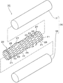
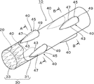
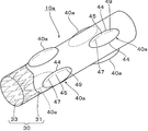
- FIG. 1 It is a disassembled perspective view which shows one Embodiment of the stent of this invention. It is a perspective view of the stent.
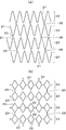
- the stent main body which comprises the stent is shown, (a) The development view, (b) is the development view of the stent main body in another example.
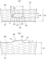
- (A) is a sectional view taken along the line AA in FIG. 2, and (b) is a sectional view taken along the line BB in FIG.
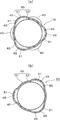
- A) is a principal part top view of the stent of this invention,
- (b) is a principal part side view of the stent. It is sectional drawing when the stent of this invention is fractured
- the stent 10 in this embodiment includes a metal stent body 20, a resin cover member 30 that covers at least a part of the outer periphery of the stent body 20, and the stent body 20. And a bulging portion 40 which is provided in a portion covered by the cover member 30 and which suppresses the movement of the stent 10 in close contact with the inner wall of the tubular organ.
- the stent body 20 is formed by processing a metal cylinder. That is, as shown in FIG. 1 and FIG. 3A, the metal cylinder is processed by laser processing, etching, or the like to form a circumferential unit 23 that is zigzag-shaped and connected in an annular shape. The bent portions are connected to each other via a connecting portion 25, and a plurality of circumferential units 23 are arranged in the axial direction to form a substantially cylindrical stent body 20.
- the stent body 20 is formed of a metal cylinder, and a circumferential unit 23 in which a plurality of frame-like bodies 22 are connected in the circumferential direction includes a plurality of connecting portions 25. It may be connected in the axial direction through a cylinder and configured in a cylindrical shape.
- the stent body 20 may be a tube formed by weaving, assembling, or entwining a metal wire to knit the metal wire.
- the material of the stent body 20 is not particularly limited.
- a self-expanding stent body 20 that is expanded at a temperature equal to or higher than the transformation point by performing shape memory processing with the diameter of the metal cylinder expanded. Can be obtained.
- the stent body 20 may be of a balloon expansion type that is expanded by a balloon catheter.
- the resin cover member 30 in this embodiment is disposed on the outer periphery 31 of the stent body 20 and the inner periphery of the stent body 20. And an inner cover 33.
- Each of the covers 31 and 33 has a cylindrical shape formed over the entire length of the stent body 20, and the covers 31 and 33 cover the entire outer periphery and inner periphery of the stent body 20. Yes.
- Examples of the material of the covers 31 and 33 include polyurethane, silicone, natural rubber, nylon elastomer, polyether block amide, polyethylene, polyvinyl chloride, vinyl acetate, and further, polytetrafluoroethylene (PTFE), par Fluorine resins such as fluoroalkoxy resin (PFA), tetrafluoroethylene-hexafluoropropylene copolymer (FEP), and tetrafluoroethylene-ethylene copolymer (ETFE) can be preferably used.
- PTFE polytetrafluoroethylene
- PFA fluoroalkoxy resin
- FEP tetrafluoroethylene-hexafluoropropylene copolymer
- ETFE tetrafluoroethylene-ethylene copolymer
- polybutadiene, styrene-based elastomer, silicone, or the like it is preferable to coat polybutadiene, styrene-based elastomer, silicone, or the like on the outer periphery of each of the covers 31 and 33, because polyurethane, nylon elastomer, and the like that are easily hydrolyzed can be protected.
- a protrusion 27 is provided on the outer periphery of the stent body 20 (see FIG. 1).
- the stent body 20 is covered with a resin cover member 30 so that it is covered with an outer cover 31 on the outer periphery of the stent body 20.
- a bulging portion 40 having a predetermined width in the circumferential direction of the stent body 20 and a predetermined length in the axial direction and a smoothly projecting shape so as to gradually become higher is provided at the broken portion. ing. That is, the outer cover 31 of the resin cover member 30 that covers the outer periphery of the stent body 20 also has a shape in which the cover member 30 is pushed out from the inside by the protrusion 27 and bulges along the shape of the protrusion 27. Yes.
- the protruding portion 27 of the stent body 20 and the bulged portion of the outer cover 31 that covers the surface thereof will be described together as the bulging portion 40.
- the bulging portions 40 are arranged at a plurality of locations at predetermined intervals along the circumferential direction of the stent body 20 and at a plurality of locations at predetermined intervals along the axial direction.
- the portion 40 is disposed at a position where it does not overlap when viewed in the axial direction from the end face of the stent body 20.
- three bulging portions 40 are arranged at equal intervals in the circumferential direction at a position near one end of the stent body 20 in the axial direction.
- three bulging portions 40 are arranged at equal intervals in the circumferential direction so as not to overlap the bulging portion 40 provided at a position near one end of the stent body 20 at a position near the other end in the axial direction.
- bulging portions 40, 40 are provided at locations facing the circumferential direction of the stent body 20, or evenly arranged in the circumferential direction of the stent body 20 as shown in FIG. 8 (b).
- Four bulging portions 40 may be provided at an appropriate interval, or a larger number of bulging portions 40 may be provided.
- the bulging portions 40 are preferably provided at a plurality of locations at predetermined intervals in the axial direction of the stent body 20, and in this case as well, as shown in FIGS. 8 (a) and 8 (b), the stent body 20 is pivoted. It is preferable that the bulging portions 40 are arranged at positions where they do not overlap when viewed from the direction end face.
- the bulging portion 40 in this embodiment has a tapered shape with a sharp tip in the axial direction, and the side edges 43 and 43 are curved while drawing the curve. It is formed in a substantially water droplet shape with a diameter that gradually increases toward the end side.
- the bulging portion 40 is arranged so that the distal end side having a tapered shape is in the extraction direction when the stent 10 is extracted.
- the portion of the bulging portion 40 along the axial direction of the stent body 20 gradually rises higher from the distal end side and rises to the top 45 (the outer periphery of the stent body 20). To the base end side from the top 45 to form a shape that gradually becomes lower. Further, as shown in FIGS. 2 and 4A and 4B, the portion of the bulging portion 40 along the circumferential direction of the stent body 20 also gradually rises from the one end in the circumferential direction to the top 45. It has a shape that gradually decreases from the top 45 toward the other end in the circumferential direction. Therefore, the bulging portion 40 has a shape that smoothly bulges as a whole without a corner portion or an edge portion on its peripheral surface.
- the inclination of the bulging portion 40 along the axial direction of the stent body 20 is a slope in the extraction direction of the stent 10 with respect to the topmost portion 45, that is, a tapered shape.
- the slope 47 is formed so that the slope of the slope 47 extending from the axial tip to the top 45 is gentler than the slope on the opposite side, ie, the slope 49 from the top 45 to the axial base. ing.
- the width W of the bulging portion 40 along the circumferential direction of the stent body 20 is 5 to 60% of the outer diameter D of the stent body 20. It is preferably 10 to 40%.
- the width W of the bulging portion 40 is less than 5% with respect to the outer diameter D of the stent body 20, the contact area of the bulging portion 40 with respect to the circumferential direction of the inner wall of the tubular organ is small, and the stent 10 can easily move. If there is a tendency and the width W exceeds 60% with respect to the outer diameter D of the stent body 20, the contact area of the bulging portion 40 with the inner wall of the tubular organ is too large, and it is difficult to take out the stent 10 from the tubular organ. Tend to be.
- the length L of the bulging portion 40 along the axial direction of the stent body 20 is preferably formed larger than the width W of the bulging portion 40. .
- the length L of the bulging portion 40 is preferably 120 to 400% and preferably 150 to 300% of the width W of the bulging portion 40. More preferred.
- the length L of the bulging portion 40 is less than 120% with respect to the width W, the stent 10 tends to move in the tubular organ, and the length L exceeds 400% with respect to the width W. In this case, the flexibility of the stent 10 tends to decrease.
- the angle of the tapered portion on the distal end side in the axial direction of the bulging portion 40 is preferably 10 to 50 °, and more preferably 20 to 45 °.
- the angle ⁇ is less than 10 °, it is difficult to secure the width of the bulging portion 40, and when it exceeds 50 °, resistance tends to occur when the stent 10 is taken out from the tubular organ.
- the height H from the outer periphery of the stent body 20 of the uppermost portion 45 of the bulging portion 40 is 10 to 40% of the outer diameter D of the stent body 20. Preferably, it is formed of 15 to 30%.
- the height H of the topmost portion 45 of the bulging portion 40 is less than 10% with respect to the outer diameter D of the stent body 20, the anchor effect on the inner wall of the tubular organ tends to be low, and the height H is the stent body 20.
- it exceeds 40% with respect to the outer diameter D the bulging portion 40 is in close contact with the inner wall of the tubular organ, which may make it difficult to remove the stent 10 from the tubular organ.
- a gap 51 is formed inside the bulging portion 40.
- the inner cover 33 is disposed on the inner periphery of the stent body 20, a gap 51 is formed between the inner cover 33 and the bulging portion 40.
- bile duct V2 and pancreatic duct V3 branch and extend from duodenum V1, but in this embodiment, a case where stent 10 is placed in bile duct V2 will be described.
- the stent 10 of the present invention can be placed in a tubular organ such as trachea, esophagus, large intestine, blood vessel, and the applied tubular organ is not particularly limited.
- the diameter of the stent 10 is reduced and accommodated in the inner periphery of the distal end of a medical tube (not shown) such as a catheter or a sheath.
- a medical tube such as a catheter or a sheath.
- the taper portion on the distal end side in the axial direction of the bulging portion 40 is directed to the proximal end side (hand side) of the medical tube, and the enlarged diameter portion on the other axial end side of the bulging portion 40 is directed to the medical tube.
- the stent 10 is accommodated in the inner periphery of the distal end portion of the medical tube toward the distal end side.
- an endoscope (not shown) is moved to the duodenum V1 through the oral cavity, stomach or the like by a well-known method, a guide wire (not shown) is introduced into the bile duct V2 through the lumen of the endoscope, and the distal end thereof is connected to the bile duct V2. To reach a position slightly beyond the constricted affected area. Thereafter, the medical tube containing the stent 10 is transported through the guide wire, and the distal end thereof reaches the affected part of the bile duct V2.
- the narrowed affected part of the bile duct V2 is pushed and expanded by the stent 10, the outer periphery of the stent 10 is in close contact with the inner wall of the bile duct V2, and each bulging part 40 enters the inner wall of the bile duct V2.
- the stent 10 is placed in the bile duct V2, so that the bulging portion 40 of the stent 10 enters and comes into close contact with the inner wall of the bile duct V2.
- it can be accurately placed in the affected area of the bile duct V2.
- it is preferable to indwell the stent 10 so that the one end part may protrude a little from the opening of the bile duct V2 (refer FIG. 7).
- the stent 10 of the present invention is not configured to be placed in the tubular organ by the biodegradable stent, unlike the double-structured stent of Patent Document 1, the stent 10 is positioned in the tubular organ for a long time. It can be stably placed without shifting.
- each bulging part 40 is arrange
- the stent 10 When the lumen of the stent 10 is blocked with a body fluid such as bile or the treatment is completed, and the stent 10 is to be taken out from the tubular organ, for example, the stent 10 protrudes from the opening of the bile duct V2. A portion (see FIG. 7) or a predetermined portion of the stent 10 is grasped with a medical snare or a medical treatment clamp, and the stent 10 is pulled out from the bile duct V2 and moved to the duodenum V1, and then a catheter or the like The stent 10 can be taken out from the body by being pulled out through.
- a body fluid such as bile or the treatment
- the bulging portion 40 has a shape that protrudes smoothly so that it gradually rises and gradually lowers, the stent 10 is pulled and the bulging portion 40 comes into close contact with the inner wall of the bile duct V ⁇ b> 2. Even if it moves, damage to the inner wall of the bile duct V2 is prevented, and the bile duct V2 can be extracted relatively smoothly.
- the outer cover 31 is disposed on the outer periphery of the stent body 20, the stent body 20 is prevented from directly adhering to the inner wall of the bile duct V2, and is tubular between the meshes of the stent body 20.
- the internal wall of the organ can be prevented from biting, and the stent 10 can be easily extracted from the tubular organ.
- the inner cover 33 is also arranged on the inner periphery of the stent body 20, it is possible to prevent bile and other body fluids from entering between the meshes of the stent body 20, and to reduce flow resistance. it can.
- the bulging portion 40 is easily deformed when the stent 10 is pulled in order to extract the stent 10 from the bile duct V2.
- the stent 10 can be extracted more smoothly.
- the slope of the bulging portion 40 along the axial direction of the stent body 20 is such that the slope of the slope 47 in the extraction direction of the stent 10 with respect to the topmost portion 45 is greater than the slope of the slope 49 on the opposite side. (See FIG. 5 (b)), when the stent 10 is extracted from the bile duct V2, the bulging portion 40 does not get caught on the inner wall of the bile duct V2, and is in close contact with the inner wall. The stent 10 can be moved by sliding, and the stent 10 can be extracted more smoothly from the bile duct V2.
- the bulging portion 40 in this embodiment is such that the length L along the axial direction is larger than the width W along the circumferential direction of the stent body 20. Therefore, the contact area of the bulging portion 40 with respect to the inner wall of the tubular organ can be ensured as large as possible in the axial direction to increase the fixing force.
- the bulging portion 40 that is long in the axial direction can be smoothly extracted while preventing damage to the ring-shaped rigid tubular organ.
- FIG. 9 illustrates another embodiment of the stent of the present invention. Note that substantially the same parts as those of the above-described embodiment are denoted by the same reference numerals, and description thereof is omitted.
- the shape of the bulging portion 40a is different from that of the above embodiment.
- the bulging portion 40a in this embodiment is formed such that the length along the axial direction of the stent body 20 is larger than the width along the circumferential direction, and gradually rises toward the top 45.
- the slope 47 on the distal end side in the axial direction and the slope 49 on the proximal end side in the axial direction gradually lowering from the top 45 have an arc shape with the same radius, and the lower peripheral edge 44 has an elliptical shape as a whole. It has a shape that swells smoothly so as to be substantially elliptical.
- the bulging portion 40a has three bulging portions 40a arranged at equal intervals in the circumferential direction at a location near one axial end of the stent body 20, and at a location near the other axial end of the stent main body 20.
- the three bulging portions 40 are arranged at equal intervals in the circumferential direction so as not to overlap the bulging portion 40a provided at a position near one end.
- the bulging portion 40a is provided at a location facing the circumferential direction of the stent body 20, the four bulging portions 40a are provided at equal intervals in the circumferential direction of the stent body 20, or A larger number of bulges 40a may be provided.
- the bulging portion 40a having a substantially elliptical shape has an arc shape in cross section along the axial direction of the stent body 20.
Abstract
Description
20 ステント本体
30 カバー部材
40,40a,40b,40c 膨出部
47,49 斜面
51 空隙
Claims (5)
- 管状器官内に留置されるステントであって、
金属製のステント本体と、このステント本体の外周の少なくとも一部を覆う樹脂製のカバー部材と、前記ステント本体の外周の、前記カバー部材により覆われた部分に設けられ、前記管状器官の内壁に密接してステントの移動を抑制する膨出部とを備え、
前記膨出部は、周方向に所定幅でかつ軸方向に所定長さで伸びると共に、次第に盛り上がり次第に低くなるように滑らかに突出した形状をなすことを特徴とするステント。 - 前記膨出部は、前記ステント本体の周方向に沿って所定間隔で複数箇所に、かつ、軸方向に沿っても所定間隔で複数箇所に配置されており、各膨出部がステント本体の端面から軸方向に見たとき重ならない位置に配置されている請求項1記載のステント。
- 前記膨出部は、前記ステント本体の周方向に沿った幅よりも軸方向に沿った長さの方が、大きくなるように形成されている請求項1又は2記載のステント。
- 前記膨出部の内側には、空隙が形成されている請求項1~3のいずれか1つに記載のステント。
- 前記膨出部の前記ステント本体の軸方向に沿った傾斜は、最頂部に対してステントの抜き出し方向となる斜面の傾斜が、その反対側の斜面の傾斜よりも緩やかになるように形成されている請求項1~4のいずれか1つに記載のステント。
Priority Applications (3)
| Application Number | Priority Date | Filing Date | Title |
|---|---|---|---|
| CN201280020779.2A CN103547238B (zh) | 2011-04-27 | 2012-04-23 | 支架 |
| EP12776498.3A EP2702964B1 (en) | 2011-04-27 | 2012-04-23 | Stent |
| JP2013512343A JP5795364B2 (ja) | 2011-04-27 | 2012-04-23 | ステント |
Applications Claiming Priority (2)
| Application Number | Priority Date | Filing Date | Title |
|---|---|---|---|
| JP2011-098892 | 2011-04-27 | ||
| JP2011098892 | 2011-04-27 |
Publications (1)
| Publication Number | Publication Date |
|---|---|
| WO2012147675A1 true WO2012147675A1 (ja) | 2012-11-01 |
Family
ID=47072194
Family Applications (1)
| Application Number | Title | Priority Date | Filing Date |
|---|---|---|---|
| PCT/JP2012/060825 WO2012147675A1 (ja) | 2011-04-27 | 2012-04-23 | ステント |
Country Status (4)
| Country | Link |
|---|---|
| EP (1) | EP2702964B1 (ja) |
| JP (1) | JP5795364B2 (ja) |
| CN (1) | CN103547238B (ja) |
| WO (1) | WO2012147675A1 (ja) |
Cited By (11)
| Publication number | Priority date | Publication date | Assignee | Title |
|---|---|---|---|---|
| WO2014171448A1 (ja) * | 2013-04-18 | 2014-10-23 | 国立大学法人 山形大学 | 胆管留置用ステント及びその製造方法 |
| JP2014217487A (ja) * | 2013-05-02 | 2014-11-20 | 日本ライフライン株式会社 | ステント |
| US8940040B2 (en) | 2011-12-06 | 2015-01-27 | Aortic Innovations, Llc | Device for endovascular aortic repair and method of using the same |
| CN105407836A (zh) * | 2013-05-23 | 2016-03-16 | 恩都思潘有限公司 | 升主动脉支架植体系统 |
| JP2016511104A (ja) * | 2013-03-13 | 2016-04-14 | ボストン サイエンティフィック サイムド,インコーポレイテッドBoston Scientific Scimed,Inc. | フルカバー付きステントのための移動防止型組織固定システム |
| JP2016515008A (ja) * | 2013-03-15 | 2016-05-26 | メリット・メディカル・システムズ・インコーポレーテッド | 食道ステント |
| US9427306B2 (en) | 2013-06-05 | 2016-08-30 | Aortic Innovations Surena, Llc | Variable depression stents (VDS) and billowing graft assemblies |
| KR20160104215A (ko) * | 2015-02-26 | 2016-09-05 | 전북대학교산학협력단 | 비혈관용 이동방지 스텐트 및 이의 제조방법 |
| EP2977030A4 (en) * | 2013-03-18 | 2016-09-28 | Piolax Medical Devices Inc | STENT |
| CN106420126A (zh) * | 2016-10-31 | 2017-02-22 | 中山大学附属第医院 | 血管支架 |
| JP2018139792A (ja) * | 2017-02-27 | 2018-09-13 | 川澄化学工業株式会社 | カバードステント |
Families Citing this family (10)
| Publication number | Priority date | Publication date | Assignee | Title |
|---|---|---|---|---|
| US8870938B2 (en) | 2009-06-23 | 2014-10-28 | Endospan Ltd. | Vascular prostheses for treating aneurysms |
| US9993360B2 (en) | 2013-01-08 | 2018-06-12 | Endospan Ltd. | Minimization of stent-graft migration during implantation |
| US10219921B2 (en) * | 2014-10-02 | 2019-03-05 | Boston Scientific Scimed, Inc. | Controlled ingrowth feature for antimigration |
| BR112017012425A2 (pt) | 2014-12-18 | 2018-01-02 | Endospan Ltd | enxerto por stent endovascular com tubo lateral resistente à fadiga |
| CN109688974B (zh) * | 2016-09-09 | 2021-04-20 | W.L.戈尔及同仁股份有限公司 | 全弓设计 |
| CN106618817A (zh) * | 2016-12-23 | 2017-05-10 | 首都医科大学附属北京儿童医院 | 婴幼儿用3d打印气管内支架及其制备方法和用途 |
| CN108720971A (zh) * | 2018-01-28 | 2018-11-02 | 杭州市第人民医院 | 一种可控抗菌气管支架 |
| US11583393B2 (en) * | 2018-12-05 | 2023-02-21 | Acclarent, Inc. | Apparatus and method to maintain patency of dilated anatomical opening |
| WO2021146021A1 (en) | 2020-01-13 | 2021-07-22 | Boston Scientific Scimed, Inc. | Anti-migration stent |
| WO2023241306A1 (zh) * | 2022-06-15 | 2023-12-21 | 微创神通医疗科技(上海)有限公司 | 一种血管支架 |
Citations (2)
| Publication number | Priority date | Publication date | Assignee | Title |
|---|---|---|---|---|
| JP2000167063A (ja) * | 1998-12-04 | 2000-06-20 | Yuichi Mori | ステントおよびステントグラフト |
| JP2011509805A (ja) * | 2008-01-24 | 2011-03-31 | メドトロニック,インコーポレイテッド | 人工心臓弁用のステント |
Family Cites Families (10)
| Publication number | Priority date | Publication date | Assignee | Title |
|---|---|---|---|---|
| US6319278B1 (en) * | 2000-03-03 | 2001-11-20 | Stephen F. Quinn | Low profile device for the treatment of vascular abnormalities |
| US7226474B2 (en) * | 2000-05-01 | 2007-06-05 | Endovascular Technologies, Inc. | Modular graft component junctions |
| US20040015224A1 (en) * | 2002-07-22 | 2004-01-22 | Armstrong Joseph R. | Endoluminal expansion system |
| CN100352406C (zh) * | 2004-08-17 | 2007-12-05 | 微创医疗器械(上海)有限公司 | 组合式可任意方向弯曲的覆膜支架 |
| CN100594014C (zh) * | 2005-12-23 | 2010-03-17 | 温宁 | 带径向突出结构的支架瓣膜及其支架的编织方法 |
| CN2910150Y (zh) * | 2006-04-27 | 2007-06-13 | 南京微创医学科技有限公司 | 可防止并发症的非血管覆膜支架 |
| CN2925418Y (zh) * | 2006-05-20 | 2007-07-25 | 张丽云 | 改进的食管支架 |
| KR100826664B1 (ko) * | 2006-11-01 | 2008-05-02 | 주식회사 엠아이텍 | 스텐트 및 이 스텐트의 제조방법 |
| CN101283937B (zh) * | 2008-05-21 | 2010-08-18 | 微创医疗器械(上海)有限公司 | 带开口的覆膜支架的束缚方法 |
| CN201227338Y (zh) * | 2008-07-31 | 2009-04-29 | 上海交通大学 | 防滑贲门支架 |
-
2012
- 2012-04-23 EP EP12776498.3A patent/EP2702964B1/en not_active Not-in-force
- 2012-04-23 WO PCT/JP2012/060825 patent/WO2012147675A1/ja active Application Filing
- 2012-04-23 CN CN201280020779.2A patent/CN103547238B/zh not_active Expired - Fee Related
- 2012-04-23 JP JP2013512343A patent/JP5795364B2/ja not_active Expired - Fee Related
Patent Citations (2)
| Publication number | Priority date | Publication date | Assignee | Title |
|---|---|---|---|---|
| JP2000167063A (ja) * | 1998-12-04 | 2000-06-20 | Yuichi Mori | ステントおよびステントグラフト |
| JP2011509805A (ja) * | 2008-01-24 | 2011-03-31 | メドトロニック,インコーポレイテッド | 人工心臓弁用のステント |
Non-Patent Citations (1)
| Title |
|---|
| See also references of EP2702964A4 * |
Cited By (21)
| Publication number | Priority date | Publication date | Assignee | Title |
|---|---|---|---|---|
| US10028848B2 (en) | 2011-12-06 | 2018-07-24 | Aortic Innovations, Llc | Device for endovascular aortic repair and method of using the same |
| US8940040B2 (en) | 2011-12-06 | 2015-01-27 | Aortic Innovations, Llc | Device for endovascular aortic repair and method of using the same |
| US10842655B2 (en) | 2011-12-06 | 2020-11-24 | Aortic Innovations, Llc | Device for endovascular aortic repair and method of using the same |
| US10792172B2 (en) | 2011-12-06 | 2020-10-06 | Aortic Innovations, Llc | Heart valve replacement device for endovascular aortic repair and method of using the same |
| US9339399B2 (en) | 2011-12-06 | 2016-05-17 | Aortic Innovations, Llc | Device for endovascular aortic repair and method of using the same |
| JP2017192780A (ja) * | 2013-03-13 | 2017-10-26 | ボストン サイエンティフィック サイムド,インコーポレイテッドBoston Scientific Scimed,Inc. | フルカバー付きステントのための移動防止型組織固定システム |
| JP2016511104A (ja) * | 2013-03-13 | 2016-04-14 | ボストン サイエンティフィック サイムド,インコーポレイテッドBoston Scientific Scimed,Inc. | フルカバー付きステントのための移動防止型組織固定システム |
| JP2016515008A (ja) * | 2013-03-15 | 2016-05-26 | メリット・メディカル・システムズ・インコーポレーテッド | 食道ステント |
| JPWO2014148122A1 (ja) * | 2013-03-18 | 2017-02-16 | 株式会社パイオラックスメディカルデバイス | ステント |
| EP2977030A4 (en) * | 2013-03-18 | 2016-09-28 | Piolax Medical Devices Inc | STENT |
| US10080640B2 (en) | 2013-04-18 | 2018-09-25 | National University Corporation Yamagata University | Stent to be placed in bile duct |
| JPWO2014171448A1 (ja) * | 2013-04-18 | 2017-02-23 | 国立大学法人山形大学 | 胆管留置用ステント及びその製造方法 |
| WO2014171448A1 (ja) * | 2013-04-18 | 2014-10-23 | 国立大学法人 山形大学 | 胆管留置用ステント及びその製造方法 |
| JP2014217487A (ja) * | 2013-05-02 | 2014-11-20 | 日本ライフライン株式会社 | ステント |
| CN105407836A (zh) * | 2013-05-23 | 2016-03-16 | 恩都思潘有限公司 | 升主动脉支架植体系统 |
| CN105407836B (zh) * | 2013-05-23 | 2018-10-02 | 恩都思潘有限公司 | 升主动脉支架植体系统 |
| US9427306B2 (en) | 2013-06-05 | 2016-08-30 | Aortic Innovations Surena, Llc | Variable depression stents (VDS) and billowing graft assemblies |
| KR20160104215A (ko) * | 2015-02-26 | 2016-09-05 | 전북대학교산학협력단 | 비혈관용 이동방지 스텐트 및 이의 제조방법 |
| KR101664009B1 (ko) | 2015-02-26 | 2016-10-10 | 전북대학교산학협력단 | 비혈관용 이동방지 스텐트 및 이의 제조방법 |
| CN106420126A (zh) * | 2016-10-31 | 2017-02-22 | 中山大学附属第医院 | 血管支架 |
| JP2018139792A (ja) * | 2017-02-27 | 2018-09-13 | 川澄化学工業株式会社 | カバードステント |
Also Published As
| Publication number | Publication date |
|---|---|
| EP2702964A4 (en) | 2015-02-18 |
| CN103547238B (zh) | 2016-01-20 |
| JPWO2012147675A1 (ja) | 2014-07-28 |
| EP2702964A1 (en) | 2014-03-05 |
| EP2702964B1 (en) | 2017-07-19 |
| CN103547238A (zh) | 2014-01-29 |
| JP5795364B2 (ja) | 2015-10-14 |
Similar Documents
| Publication | Publication Date | Title |
|---|---|---|
| JP5795364B2 (ja) | ステント | |
| US10952878B2 (en) | Methods and systems for increasing a density of a region of a vascular device | |
| JP5719327B2 (ja) | らせん状ステント | |
| JP5921682B2 (ja) | ステント | |
| JP5813230B2 (ja) | ステント | |
| EP2684545B1 (en) | Stent | |
| JP6353933B2 (ja) | ステント | |
| JP2020507396A (ja) | 拡張性を備えるイントロデューサー | |
| KR20160079078A (ko) | 관내 디바이스 | |
| WO2014148122A1 (ja) | ステント | |
| EP3811899B1 (en) | Stent for bypass between hollow organs and stent delivery system including stent for bypass between hollow organs | |
| JP6458165B2 (ja) | ステント | |
| JP2023134841A (ja) | 非外傷性スペーサを備えたステント | |
| JP4835113B2 (ja) | ステント | |
| JP2017070406A (ja) | ステント | |
| JP6925869B2 (ja) | ステント | |
| JP6199181B2 (ja) | ステント | |
| JP6605907B2 (ja) | ステント | |
| US20200146701A1 (en) | Intraluminal foreign object capturing tool |
Legal Events
| Date | Code | Title | Description |
|---|---|---|---|
| 121 | Ep: the epo has been informed by wipo that ep was designated in this application |
Ref document number: 12776498 Country of ref document: EP Kind code of ref document: A1 |
|
| DPE1 | Request for preliminary examination filed after expiration of 19th month from priority date (pct application filed from 20040101) | ||
| ENP | Entry into the national phase |
Ref document number: 2013512343 Country of ref document: JP Kind code of ref document: A |
|
| NENP | Non-entry into the national phase |
Ref country code: DE |
|
| REEP | Request for entry into the european phase |
Ref document number: 2012776498 Country of ref document: EP |
|
| WWE | Wipo information: entry into national phase |
Ref document number: 2012776498 Country of ref document: EP |