WO2012147560A1 - 撮像装置および撮像方法 - Google Patents
撮像装置および撮像方法 Download PDFInfo
- Publication number
- WO2012147560A1 WO2012147560A1 PCT/JP2012/060318 JP2012060318W WO2012147560A1 WO 2012147560 A1 WO2012147560 A1 WO 2012147560A1 JP 2012060318 W JP2012060318 W JP 2012060318W WO 2012147560 A1 WO2012147560 A1 WO 2012147560A1
- Authority
- WO
- WIPO (PCT)
- Prior art keywords
- eye
- image
- unit
- focused
- image processing
- Prior art date
Links
Images


Classifications
-
- G—PHYSICS
- G02—OPTICS
- G02B—OPTICAL ELEMENTS, SYSTEMS OR APPARATUS
- G02B7/00—Mountings, adjusting means, or light-tight connections, for optical elements
- G02B7/28—Systems for automatic generation of focusing signals
- G02B7/36—Systems for automatic generation of focusing signals using image sharpness techniques, e.g. image processing techniques for generating autofocus signals
- G02B7/365—Systems for automatic generation of focusing signals using image sharpness techniques, e.g. image processing techniques for generating autofocus signals by analysis of the spatial frequency components of the image
-
- H—ELECTRICITY
- H04—ELECTRIC COMMUNICATION TECHNIQUE
- H04N—PICTORIAL COMMUNICATION, e.g. TELEVISION
- H04N23/00—Cameras or camera modules comprising electronic image sensors; Control thereof
- H04N23/60—Control of cameras or camera modules
- H04N23/61—Control of cameras or camera modules based on recognised objects
- H04N23/611—Control of cameras or camera modules based on recognised objects where the recognised objects include parts of the human body
-
- H—ELECTRICITY
- H04—ELECTRIC COMMUNICATION TECHNIQUE
- H04N—PICTORIAL COMMUNICATION, e.g. TELEVISION
- H04N23/00—Cameras or camera modules comprising electronic image sensors; Control thereof
- H04N23/60—Control of cameras or camera modules
- H04N23/63—Control of cameras or camera modules by using electronic viewfinders
- H04N23/631—Graphical user interfaces [GUI] specially adapted for controlling image capture or setting capture parameters
- H04N23/632—Graphical user interfaces [GUI] specially adapted for controlling image capture or setting capture parameters for displaying or modifying preview images prior to image capturing, e.g. variety of image resolutions or capturing parameters
-
- H—ELECTRICITY
- H04—ELECTRIC COMMUNICATION TECHNIQUE
- H04N—PICTORIAL COMMUNICATION, e.g. TELEVISION
- H04N23/00—Cameras or camera modules comprising electronic image sensors; Control thereof
- H04N23/60—Control of cameras or camera modules
- H04N23/63—Control of cameras or camera modules by using electronic viewfinders
- H04N23/633—Control of cameras or camera modules by using electronic viewfinders for displaying additional information relating to control or operation of the camera
- H04N23/635—Region indicators; Field of view indicators
-
- H—ELECTRICITY
- H04—ELECTRIC COMMUNICATION TECHNIQUE
- H04N—PICTORIAL COMMUNICATION, e.g. TELEVISION
- H04N23/00—Cameras or camera modules comprising electronic image sensors; Control thereof
- H04N23/60—Control of cameras or camera modules
- H04N23/67—Focus control based on electronic image sensor signals
- H04N23/673—Focus control based on electronic image sensor signals based on contrast or high frequency components of image signals, e.g. hill climbing method
-
- H—ELECTRICITY
- H04—ELECTRIC COMMUNICATION TECHNIQUE
- H04N—PICTORIAL COMMUNICATION, e.g. TELEVISION
- H04N23/00—Cameras or camera modules comprising electronic image sensors; Control thereof
- H04N23/60—Control of cameras or camera modules
- H04N23/67—Focus control based on electronic image sensor signals
- H04N23/675—Focus control based on electronic image sensor signals comprising setting of focusing regions
Definitions
- the present invention relates to an imaging apparatus and an imaging method, and more particularly, to an imaging apparatus and an imaging method such as a camera that can automatically focus on the eyes of a person or animal as a subject.
- an automatic focus detection device of an imaging device such as a digital camera performs focusing so that the contrast of a captured image is the highest.
- a face detection function has been added to this automatic focus detection device, and when a face is detected, the face AF that performs focusing at the position where the average value of the contrast of the entire detected face area is the highest is known. It has been. More recently, a function of focusing only on the eyes detected in the face area (hereinafter referred to as eye AF) is known.
- eye AF a function of focusing only on the eyes detected in the face area
- Patent Documents 1 and 2 disclose an imaging apparatus that focuses on eyes when performing portrait photography.
- the depth of field will be shallow, so that the eyes of the subject, animals, etc. will be in focus, and other peripheral face areas will be moderate. It is possible to easily achieve a drawing technique with a blurred expression.
- a medium telephoto large-diameter lens is generally expensive and large and heavy, so that it cannot be used easily by general users.
- a relatively inexpensive small and lightweight lens that can be easily purchased and handled by general users has a large open F value and a deep depth of field. For this reason, it is not easy to obtain the above-mentioned drawing effect even with a camera having an eye AF function.
- the drawing effect is substantially determined by the distance between the camera and the main subject (eyes) and the distance relationship between the camera and the main subject (eyes). Even if an entry user who does not have a habit of shooting close to the subject uses an expensive lens and sets the portrait mode, there is a possibility that the desired effect cannot be obtained.
- An object of the present invention is to provide an imaging apparatus and an imaging method.
- An imaging apparatus is an imaging apparatus capable of capturing a digital image having an imaging unit, and a facial organ detection unit that detects eyes from the digital image captured by the imaging unit; An eye AF unit that sets an AF area for the detected eye and focuses the eye; an image processing unit that performs image processing on the digital image to blur the periphery of the eye that the eye AF unit has focused;
- An image pickup apparatus is an image pickup apparatus having an image pickup unit capable of taking a digital image, and detecting an eye from the digital image picked up by the image pickup unit and focusing the eye on the eye AF And an aperture value setting unit that sets the aperture value at the time of exposure to a predetermined value in the vicinity of the open F value when the eye is focused by the eye AF unit.
- An imaging method is an imaging method of an imaging apparatus capable of taking a digital image, detecting an eye from the captured digital image, focusing on the detected eye, and The digital image is subjected to image processing that blurs the periphery of the eye that has been focused.
- an imaging apparatus and an imaging method capable of easily capturing an image having a drawing effect on eyes without making complicated settings even with a dark lens having a wide open F value. it can.
- FIG. 1 is a block diagram mainly showing an electrical configuration of a camera according to an embodiment of the present invention. It is the external appearance perspective view seen from the back side of the camera concerning one Embodiment of this invention.
- 4 is a flowchart illustrating a main operation of the camera according to the embodiment of the present invention. It is a figure which shows the operation
- the camera concerning one embodiment of the present invention it is a figure showing the example of the wire frame created by detecting the point of the face at the time of organ detection. It is a flowchart which shows the operation
- a camera according to a preferred embodiment of the present invention is a digital camera, includes an imaging unit, converts a subject image into image data by the imaging unit, and converts the subject image into a main body based on the converted image data.
- the live view is displayed on the display unit 115 arranged on the back of the screen. The photographer determines the composition and the photo opportunity by observing the live view display.
- the acquired image data is recorded on the recording medium (external memory 114).
- the recording medium external memory 114.
- the image data recorded on the recording medium can be reproduced and displayed on the display unit 115 when the reproduction mode is selected.
- FIG. 1 is a block diagram mainly showing an electrical configuration of a camera 100 according to an embodiment of the present invention.
- An aperture mechanism 103, a shutter 105, and an image sensor 107 are disposed on the optical axis of the photographing lens 101.
- the output of the image sensor 107 is connected to the A / D converter 109, and the output of the A / D converter 109 is connected to the memory 110.
- the memory 110 is connected to the image processing unit 111 and the system control unit 116.
- the system control unit 116 includes an imaging control unit 108, a shutter control unit 106, an aperture control unit 104, a lens control unit 102, an exposure control unit 112, an AF processing unit 113, a flash control unit 121, a nonvolatile memory 118, and an external memory 114.
- the display unit 115, the operation unit 117, and the power control unit 120 are connected to each other.
- the above-described imaging control unit 108 is connected to the imaging element 107, the shutter control unit 106 is connected to the shutter 105, the aperture control unit 104 is connected to the aperture mechanism 103, and the lens control unit 102 is an imaging lens. 101.
- the power control unit 120 is connected to the power supply unit 119, and the flash control unit 121 is connected to the flash charging unit 122 and the flash light emitting unit 123, respectively.
- the photographing lens 101 is an optical system for condensing a subject light beam on the image sensor 107 and forming a subject image.
- the photographing lens 101 is moved in the optical axis direction by the lens control unit 102 that operates in response to an instruction from the system control unit 116, and the focus state changes.
- the diaphragm mechanism 103 adjusts the incident amount of the subject light beam incident on the image sensor 107 via the photographing lens 101.
- the aperture amount of the aperture mechanism 103 is controlled by the aperture controller 104 that operates in accordance with an instruction from the system controller 116.
- the aperture control unit 104 and the system control unit 116 function as an aperture value setting unit that sets the aperture value at the time of exposure to a predetermined value near the open F value when the eyes are focused by an eye AF unit described later. To do.
- the shutter 105 opens and closes the light flux of the subject image formed by the photographing lens 101, and is configured by a known lens shutter, focal plane shutter, or the like.
- the shutter opening time (shutter speed value) of the shutter 105 is controlled by the shutter control unit 106 that operates in accordance with an instruction from the system control unit 116.
- the image sensor 107 is a two-dimensional solid-state image sensor such as a CMOS image sensor or a CCD image sensor.
- a Bayer array RGB color filter disposed on the front surface, a photodiode array corresponding to the RGB color filter, and the like. It is comprised from the photoelectric conversion element.
- An imaging region is configured by a pixel group including each color filter and a corresponding photoelectric conversion element.
- the image sensor 107 receives the light collected by the photographing lens 101 by each pixel and converts it into a photocurrent, accumulates this photocurrent in each capacitor, and outputs it as an analog voltage signal (image signal). Output to.
- the imaging control unit 108 controls the operation of the imaging element 107 in accordance with an instruction from the system control unit 116.
- the A / D converter 109 converts an analog voltage signal (image signal) output from the image sensor 107 into a digital image signal (image data).
- the memory 110 is a storage unit that temporarily stores various data such as image data obtained by the A / D conversion unit 109 and image data processed by the image processing unit 111.
- image data obtained by the A / D conversion unit 109 and image data processed by the image processing unit 111.
- the image includes not only the signal A / D converted by the A / D converter 109 but also the image processed signal. Sometimes referred to as data.
- the image processing unit 111 reads the image data temporarily stored in the memory 110, and performs image processing such as white balance correction processing, synchronization processing, and color conversion processing on the image data. Further, the image processing unit 111 performs image compression when recording in the external memory 114 described later, and decompresses the compressed image data read from the external memory 114.
- the image processing unit 111 functions as a face detection unit, and detects a face from the subject based on the image data. When a face is detected, the position and size of the face are also detected.
- the image processing unit 111 also functions as a facial organ detection unit, and detects organs in the face such as eyes, nose, mouth, mouth corner, and pupil. Here, when organs such as eyes and pupils are detected, the left and right eyes are detected, their positions and sizes are also detected, and the orientation of the face is also detected based on the positions and the like of these organs.
- the image processing unit 111 performs a blurring process on the original image to generate a blurred image.
- the image processing unit 111 creates an ⁇ channel mask pattern (see FIGS. 11 and 12) described later, and performs synthesis processing of the ⁇ channel mask pattern and the blurred image.
- the image processing unit 111 performs image processing for blurring the periphery of the eye that has been focused by the eye AF unit, which will be described later, or the eye that has not been focused. In addition to this, the image processing for blurring the periphery of the area including the focused eye and one of the left and right mouth corners corresponding to the position of the focused eye is performed. .
- the image processing unit 111 performs image processing for increasing the blur intensity and blurring according to the distance on the image from the eye that the eye AF unit has focused. Further, the image processing unit 111 is a distance on the image from an area including the eye that the eye AF unit has focused and one of the left and right mouth corners corresponding to the position of the focused eye. Depending on, image processing is performed by increasing the blur strength and blurring. Further, when the catchlight effect is set, the image processing unit 111 performs image processing to superimpose a catchlight pattern such as a cross shape, a star shape, or a crescent shape in a human eye.
- a catchlight pattern such as a cross shape, a star shape, or a crescent shape in a human eye.
- the exposure control unit 112 calculates the subject brightness (brightness of the scene including the subject) using the image data temporarily stored in the memory 110.
- the subject brightness may be calculated using a dedicated photometric sensor.
- AF (Auto Focus) processing unit 113 extracts a high frequency component from the image data temporarily stored in memory 110, and acquires a contrast value by integration processing. Based on the contrast value, the system control unit 116 performs drive control through the lens control unit 102 so that the photographing lens 101 is in the in-focus position. In obtaining the contrast value, the entire screen can be obtained, but the contrast value can also be obtained based on the image data corresponding to the set AF frame.
- the AF processing unit 113 and the system control unit 116 function as an eye AF unit that sets an AF area for the eyes detected by the face organ detection unit and focuses the eyes.
- the eye AF unit selects the closer, that is, the larger of the left and right eyes detected by the face organ detection unit, and focuses the selected eye.
- the operation unit 117 operates a power button 117a, a release button 117b, a shooting mode dial 117c, a moving image button 117d, a function button 117e, a cross button 117f, an OK button 117g, a menu button 117h, various input keys and the like as shown in FIG. Includes members.
- the system control unit 116 executes various sequences according to the user's operation.
- the power button 117a in the operation unit 117 is an operation member for instructing the power on / off of the camera 100.
- the system control unit 116 is turned on when the power button 117a is pressed, and the power is turned off when the power button 117a is pressed again. .
- the release button 117b has a two-stage switch including a 1st release switch and a 2nd release switch.
- the 1st release switch is turned on.
- the release button 117b is further pressed halfway and fully pressed, the 2nd release switch is turned on.
- the system control unit 116 executes a shooting preparation sequence such as AE processing and AF processing.
- the system control unit 116 executes a still image shooting sequence to perform shooting.
- the system control unit 116 is configured by an ASIC (Application Specific Integrated Circuit) including a CPU (Central Processing Unit) and the like, and the camera 100 such as the imaging control unit 108 and the flash control unit 121. Centrally control various sequences.
- ASIC Application Specific Integrated Circuit
- CPU Central Processing Unit
- the external memory 114 is, for example, a recording medium that can be attached to and detached from the camera body, and stores the image data compressed in the image processing unit 111 and its associated data. The recorded image data is read out and reproduced and displayed on the display unit 115.
- the recording medium for recording image data or the like is not limited to an external memory that can be attached to and detached from the camera body, but may be a recording medium such as a hard disk built in the camera body.
- the display unit 115 includes a liquid crystal monitor 115a (see FIG. 2) disposed on the back surface of the camera body and the like, and performs live view display based on image data. In addition, the display unit 115 reproduces and displays the captured image recorded in the external memory 114, and further displays a menu screen for setting an exposure control value and the like and setting a shooting mode and the like.
- the display unit 115 is not limited to a liquid crystal monitor as long as it can display an image or the like, and may be a display such as an organic EL.
- the catchlight pattern has a cross shape, a star shape, a crescent shape, etc., and the pattern shape is also set when setting the catchlight effect. Details of effect setting in the eye drawing effect mode will be described later with reference to FIG. Further, a touch panel is provided on the front surface of the display monitor 115 a, and information on the touch position is output to the system control unit 116 when touched by a user's finger or the like.
- the nonvolatile memory 118 is an electrically rewritable nonvolatile memory, and stores various parameters necessary for the operation of the camera 100.
- the nonvolatile memory 118 also stores a program executed by the system control unit 116.
- the system control unit 116 reads parameters stored in the non-volatile memory 118 according to a program stored in the non-volatile memory 118, and executes various sequences.
- the power supply unit 119 supplies power necessary for the operation of each unit of the camera 100, and includes a power supply battery such as a secondary battery.
- the power supply control unit 120 controls the power supply unit 119 such as detection of a power supply voltage and a remaining amount of a battery constituting the power supply unit 119.
- the flash control unit 121 controls the charging operation in the flash charging unit 122 and the light emitting operation in the flash light emitting unit 123 in accordance with an instruction from the system control unit 116.
- the flash charging unit 122 includes a booster circuit that boosts the power supply voltage of the power supply unit 119 and a capacitor that stores energy using the boosted voltage.
- the flash charging unit 122 stores energy necessary for the flash light emitting unit 123 to emit light.
- the flash light-emitting unit 123 includes, for example, a light-emitting tube such as a xenon (Xe) tube and a reflector, and the energy stored in the capacitor of the flash charging unit 122 when the light-emission instruction is received from the flash control unit 121. Use to emit light.
- FIG. 2 is an external view of the camera 100 as seen from the back side.
- the interchangeable lens 20 is attached to the camera body 10.
- a power button 117a, a release button 117b, and a shooting mode dial 117c are arranged on the upper surface of the camera body 10.
- a liquid crystal monitor 115a is disposed on the back of the camera body 10, thereby performing various displays such as a live view display of a subject image, a menu screen display, and a playback display of a recorded image.
- a moving image button 117d and a function button 117e are arranged on the upper right side of the rear surface of the camera body 10, and a cross button 117f, an OK button 117g, and a menu button 117h are arranged below these buttons. Yes.
- the cross button 117f can confirm the item selected by the cursor by moving the cursor on the screen displayed on the liquid crystal monitor 115a and pressing the OK button 117g.
- the menu button 117h is operated, a menu screen is displayed.
- the flow shown in FIG. 3 is a main routine operation. This main routine starts executing when the power button 117a of the operation unit 117 is turned on.
- live view display is first performed (S1).
- an image signal output from the image sensor 107 is subjected to image processing for live view display by the image processing unit 111, and the processed image data is displayed on the liquid crystal monitor 115 a of the display unit 115.
- the photographer looks at this live view display, determines the composition of the still image or moving image, and determines the shutter timing.
- the image processing unit 111 uses the image data to detect whether a face is included in the subject image by various methods such as a matching method and a face color.
- step S5 face frame display is performed (S5).
- the face frame is displayed on the subject image displayed on the liquid crystal monitor 115a as to the face portion of the subject, such as the face frames 30a and 31a to 31d. This is done by superimposing a white frame.
- the face frame is not limited to the white frame as long as it displays the face portion, and other display methods may be used.
- step S7 If the face frame is displayed in step S5 or if the result of determination in step S3 is that no face has been detected, it is next determined whether or not touch detection has been performed (S7). If the user intends to perform eye AF, focus on one eye, and perform image processing with an eye drawing effect that blurs the unfocused eye, etc., it is displayed on the screen of the LCD monitor 115a. The touched eye drawing icon 115b (see FIG. 9A) is touched to set the eye drawing effect mode. Therefore, in this step, it is determined whether or not the screen of the liquid crystal monitor 115a is touched.
- step S9 touch detection processing is performed (S9).
- touch detection processing is performed (S9).
- whether or not the touched icon is the eye drawing icon 115b, and if the eye drawing icon 115b is touched, settings for the eye drawing effect such as a blur level and a blur position are performed. . Detailed operation of this touch detection process will be described later with reference to FIG.
- step S21 it is next determined whether or not a first release operation has been performed (S21).
- a first release operation it is determined whether or not the release button 117b of the operation unit 117 is half-pressed and the 1st release switch is turned on. If the result of this determination is that the first release operation has not been performed, processing returns to step S1 and live view display or the like is executed.
- the maximum face AF frame is selected (S23).
- the face having the maximum size is selected from the faces detected in the face detection in step S3, and the face AF frame is superimposed on the subject image.
- the face frame 31a selected as the selected face AF frame may be distinguished by changing the color of the frame so that the face frame 31a can be distinguished.
- step S25 it is next determined whether or not the face size is larger than a predetermined value (S25).
- a predetermined value it is determined whether or not the maximum face selected in step S23 is larger than a predetermined value. If the face is small, it is difficult to detect the eye part of the facial organ, so the predetermined value for determination in this step is whether the face is large enough to detect the eye. Any numerical value can be used as long as it can be determined.
- a fixed value may be used such that the focus change, that is, the degree of blurring becomes large at a distance of about the face depth (about 10 cm).
- the degree of defocusing varies depending on the focal length of the lens, the distance from the camera to the face, the aperture value, etc., instead of using a fixed value, it is calculated based on these values to determine a predetermined value. May be.
- step S25 If the result of determination in step S25 is that the face size is larger than a predetermined value, then face organ detection is performed (S27).
- the image processing unit 111 detects a facial organ of a person's face, that is, an eye, a nose, a mouth, a mouth corner, and the like in a subject. When eyes are detected, the left and right eyes are detected.
- an eye AF frame is selected (S29).
- the larger one of the left and right eyes is selected.
- the determination may be made based on the diameter of the black eye (pupil).
- the eye AF frame is set so that the eye is in focus.
- the image processing unit 111 detects node points such as eyes, mouth, nose, chin, forehead, eyebrows, and eyebrows, and connects these points as shown in FIG.
- the wire frame is formed, and the angle of the direction in which the face is facing is calculated based on the wire frame.
- node points as shown in FIG. 7, the left eyebrow node point 41, the right eyebrow node point 42, the left eye node point 43, the right eye node point 44, the nose node point 45, and the left mouth node point 46 There is a node point 47 at the right mouth.
- the center line passing through the forehead, between the eyebrows, the nose, and the chin is biased to the left with respect to the face contour line. Therefore, it is determined to be leftward, and the angle can be calculated based on how the center line is biased.
- the center line passing through the forehead, between the eyebrows, the nose, and the chin is substantially in the center with respect to the contour line of the face, so that it is determined to face front.
- the closest eye may be judged only by the face orientation. For example, if the face is facing right, the left eye AF frame is selected. Since the subject person is facing the right side, the left eye is facing the camera side, and therefore the left eye AF frame is selected. On the other hand, if it is on the left side, the right eye AF frame is selected. Since the subject person is facing left, the right eye is facing the camera, and therefore the right eye AF frame is selected.
- the predetermined value in step S25 may be set so that it can be detected whether the eye AF frame is larger than the bust-up shooting size so that the eye AF frame does not become too small. Further, when displaying the eye AF frame, these aspect ratios may be different so that the distinction between the eye AF frame and the face AF frame can be seen at a glance.
- the face frame is shown as a square, the eye AF frame is preferably a horizontally long rectangle.
- the aperture value is then set to a predetermined value for the eye AF frame (S31).
- the aperture mechanism 103 is set to the full aperture value. It should be noted that an aperture value close to the open aperture value may be used instead of the open aperture value.
- contrast AF is performed (S33).
- the AF processing unit 113 uses the image data of the eye AF frame selected in step S29 or the image data in the maximum face AF frame selected in step 23 when the eye AF frame is not selected. Acquires the contrast value obtained by integrating the high-frequency components of the image data.
- the system control unit 116 moves the photographing lens 101 through the lens control unit 102 so that the contrast value becomes a peak value, and performs focus adjustment control.
- contrast AF is performed
- photometry is performed (S35).
- the subject brightness is obtained using the image data of the portion where the eye AF frame or the maximum face AF frame is selected. If the entire face is to be properly exposed, even if the eye AF frame is selected, the subject is measured using the image data of the face frame portion of the face for which the eye AF frame is selected as the photometric value. The luminance may be obtained.
- exposure calculation is performed (S37).
- the system control unit 116 calculates an exposure control value such as a shutter speed, an aperture value, and an ISO sensitivity for appropriate exposure by apex calculation or table reference. Note that, when the eye-drawing effect mode is selected on the menu screen, the shutter speed and ISO sensitivity at which proper exposure is performed are calculated based on the aperture value set in step S31.
- step S39 it is next determined whether or not the first release operation is continued (S39).
- the release button 117b is half-pressed in step S21, the process proceeds to step S13 and subsequent steps, but it is determined whether the half-press of the release button 117b is continued at the time of the determination in step S39. If the result of this determination is that the first release operation has not been continued, the process returns to step S1 because the hand has been released from the release button 117b.
- step S39 determines whether or not the 1st release operation has continued.
- step S41 determines whether or not the release button 117b of the operation unit 117 is fully pressed and the 2nd release switch is turned on.
- the process returns to step S1.
- step S43 If the result of determination in step S41 is that a 2nd release operation has been performed, still image shooting is performed (S43).
- image data of a still image from the image sensor 107 is acquired.
- the aperture value at the time of exposure is set by the aperture value setting unit composed of the aperture control unit 104 and the system control unit 116. Is set in the vicinity of the open F value.
- step S51 If the result of determination in step S51 is to link eye drawing effects, it is next determined whether eye AF has been performed (S53). Here, it is determined whether or not the subject in the eye AF frame has been focused when the contrast AF is performed in step S33.
- step S55 eye drawing effect processing is next performed (S55).
- the image processing of the eye drawing effect for blurring images such as the periphery of the eye that has been focused and the eye that has not been focused is performed. Detailed operation of the eye drawing effect processing will be described later with reference to FIG.
- step S55 If the eye drawing effect process is performed in step S55, or if the eye AF is not performed as a result of the determination in step S53, or if the eye drawing effect is not linked as a result of the determination in step S51, then the recording process is performed. Perform (S57).
- the image data acquired in step S43 or the eye-drawing effect processing is performed, the image data that has been subjected to the blurred image processing is recorded in the external memory 114.
- the recording process returns to step S1.
- eyes are detected from the captured digital image when detecting the facial organs (S27), the detected eyes are focused (S29, S33), and the digital image is focused.
- Image processing for blurring the periphery of the performed eye is performed (S55).
- the left and right eyes are detected when performing facial organ detection (S27), and the closer one of the left and right eyes, that is, the larger one is selected (S29).
- An operation for focusing is performed (S33), and image processing for blurring the eyes not selected is performed (S55).
- step S9 the touch detection process in step S9 during live view display before the first release operation will be described with reference to the flowchart shown in FIG.
- the flow of the touch detection process is started by touching the monitor surface of the liquid crystal monitor 115a.
- the touch detection process flow it is first determined whether or not the eye drawing icon 115b has been touched (S61). As described above, in order to set the eye-drawing effect mode, the user touches the eye-drawing icon 115b (see FIG. 9A) displayed on the liquid crystal monitor 115a. The determination is made based on the touch position detection signal. If the result of this determination is that the eye drawing icon 115b has not been touched, other touch processing is performed (S91). When a screen other than the eye drawing icon 115b is touched during live view display, processing corresponding to the touch position is performed, and when the processing is completed, the original flow is restored.
- step S61 If the result of determination in step S61 is that the eye drawing icon 115b has been touched, the blur level setting screen is then displayed (S63).
- the blur level guide 115c, the blur level bar 115d, the mask intensity level guide 115e, the mask intensity level bar 115f, and the return icon 115g shown in FIG. 9B are displayed.
- the blur level guide 115c and the blur level bar 115d are icons for setting the blur level, and the blur level is set by moving the blur level bar 115d along the blur level guide 115c by a touch operation.
- the mask intensity level guide 115e and the mask intensity level bar 115f are icons for setting an ⁇ channel mask pattern.
- the mask intensity level bar 115f is blurred by moving the mask intensity level bar 115f by a touch operation along the mask intensity guide 115e. Set the steepness of change and the size of the area to be blurred.
- the return icon 115g returns to the original flow from the touch detection processing flow by touching the icon.
- the blur setting level screen When the blur setting level screen is displayed, it is next determined whether or not the setting screen is touched / dragged (S65). As an area not subjected to the blurring process, an AF setting point can be set or an area touched / dragged by the user on the screen of the liquid crystal monitor 115a can be set (see FIG. 12). In this step, it is determined based on the touch position detection signal from the display unit 115 whether or not the user has set an area for which the blurring process is not performed.
- step S65 If the result of determination in step S65 is that there is no touch / drag on the setting screen, the AF setting point is set to the center without blurring (S67). The position of the face AF frame (AF setting point) set in step S5 is set so as not to perform the blurring process. On the other hand, if the result of determination in step S65 is touch / drag on the setting screen, the touch point or drag line is set to the center without blurring (S69).
- step S71 it is next determined whether or not a blur level bar operation has been performed (S71). It is determined based on the touch position detection signal from the display unit 115 whether or not the blur level bar 115d described above has been moved by a touch operation.
- step S73 the blur intensity is changed (S73).
- the blur intensity can be changed by sliding the blur level bar 115d in the focused image shown in FIG. 10A, as shown in FIG. 10B.
- step S71 determines whether or not the blur intensity level bar operation has been performed. If the blur intensity is changed, or if the result of determination in step S71 is that the blur level bar operation has not been performed, it is next determined whether or not the mask intensity level bar operation has been performed (S75). Whether or not the above-described mask intensity level bar 115f has been moved by a touch operation is determined based on a touch position detection signal from the display unit 115.
- the ⁇ channel mask pattern is changed (S77).
- the ⁇ channel mask pattern is a mask whose transmittance changes as shown in FIGS. 11 and 12, and is used when the blurred image and the original image are synthesized.
- the density of the ⁇ channel mask pattern represents the transparency of the image. The black part does not transmit, and the white part transmits.
- the transmittance of the ⁇ channel mask pattern has the highest blurring center set in step S67 or S69. If the mask intensity level bar 115f is lowered from this state, the transmittance of the peripheral portion is increased, as shown in FIG. Thus, the ⁇ channel mask pattern changes according to the mask intensity level bar operation.
- the ⁇ channel mask pattern creates two patterns, an original pattern created according to the mask intensity level bar operation and an inverted pattern obtained by inverting the original pattern.
- the original pattern is for the original image, and the reverse pattern is for the blurred image.
- 11A and 11B show the case where the point is set as the blur center, but the point in this case is not limited to the center of the screen.
- the screen may be set around the screen. If the user draws a line by dragging the screen of the liquid crystal monitor 115a with a finger in step S69, the transparent portion of the ⁇ channel mask pattern becomes a line shape as shown in FIG.
- step S77 if the ⁇ channel mask pattern is changed, a live view (LV) frame image is acquired (S79), and an original image is created (S81).
- LV live view
- S81 an image signal output from the image sensor 107 is subjected to image processing for live view display by the image processing unit 111, and this image is handled as an original image.
- a blurred image is created (S83).
- the image processing unit 111 generates a blurred image according to the blur intensity changed in step S73 (see FIG. 10B).
- the original image and the blurred image are synthesized (S85).
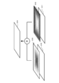
- an image in which the original image 201 created in step S81 is transmitted through the ⁇ channel mask pattern 202 created in step S77 is generated.
- This transmitted image is an original image and a focused part.
- an image is generated in which the blurred image 205 created in step S83 is transmitted through the mask 206 of the reverse pattern of the ⁇ channel mask pattern created in step S77.
- This transmitted image is a blurred image.
- the image creation effect imparted image 209 can be obtained by synthesizing the images transmitted through the mask 202 and the mask 206.
- the periphery of the non-blurred center set in step S67 or S69 is an original image in focus, and the peripheral portion away from the blur center is a blurred image.
- step S87 live view display is performed (S87).
- the image acquired in step S79 and synthesized in step S85 is displayed in live view on the display unit 115.
- step S63 the return icon 115g (see FIG. 9B) is displayed on the display unit 115. Whether or not the user touches the return icon 115g is determined based on a touch position detection signal from the display unit 115.
- step S89 If the result of determination in step S89 is that there is no touch, processing returns to step S65. On the other hand, if it has been touched, it returns to the original flow.
- the blur level setting screen is displayed, and the setting of the blur-free center, the blur level, and the mask intensity level are performed. For this reason, it is possible to adjust so as to obtain a blurring effect of the screen position intended by the user while viewing the live view display image.
- blur processing is performed with an AF point (not shown) when there is no face or a touched point as the center without blur. Further, the set values of the blur level and the mask strength level are also reflected in the eye drawing effect process in step S55.
- a catchlight is an effect image in which marks such as a cross, a star, and a crescent moon are superimposed on a person's eyes.
- the catchlight effect is set on the menu screen (see FIG. 20)
- the determination is made in this step based on the setting on the menu screen.
- step S101 determines whether the result of determination in step S101 is to provide a catchlight effect.
- a catchlight effect process is performed (S103).
- a catchlight pattern is generated, and a synthesis process is performed in which the catchlight pattern is superimposed on the eyes of the person in the still image acquired in step S43 (see FIG. 3). Detailed operation of the catchlight effect process will be described later with reference to FIG.
- step S101 If the catchlight effect process is performed or if the result of determination in step S101 is that the catchlight effect is not applied, it is next determined whether or not to apply the blur effect (S105). The determination is made based on whether or not the blur effect has been selected on the menu screen. When the blur effect is set, the blur effect is given.
- step S107 a blur effect process is performed (S107).
- a process of giving a blur effect to the image data of the still image acquired in step S43 is performed. Note that when the catchlight effect process is performed in step S103, a blur effect is given to the image data.
- step S105 When the blur effect process is performed, or when the blur effect is not given as a result of the determination in step S105, the eye drawing effect process is terminated and the process returns to the original flow.
- step S103 the catch light effect processing in step S103 will be described using the flowchart shown in FIG.
- an original image is generated (S111).
- the image data of the still image acquired in step S43 is used as the original image.
- a catchlight pattern is then generated (S113).
- a catchlight pattern P such as a star shape, a cross shape, or a crescent shape is generated according to the amount of blurring of the eyes or the size of the pupil. Details of the catch light pattern generation operation will be described later with reference to FIG.
- the original image and the pupil image are synthesized (S115).
- a pupil image (PL, PR described later) in which the catchlight pattern generated in step S113 is combined with the original image generated in step S111.
- the original flow is restored.
- catch light pattern generation in step S113 will be described using the flowchart shown in FIG.
- the pattern P set in the menu is enlarged or reduced to the size of the pupil (S121).
- the catchlight pattern is set on the menu screen, and the size of the pupil in the eye is detected by the image processing unit 111.
- the left eye blur amount CLE is acquired (S123).
- the AF processing unit 113 calculates and acquires the blur amount CLE of the left eye part.
- the blur amount CLE is calculated because the blur amount of the pupil portion changes depending on the focus state of the photographic lens 103, whereas the catchlight pattern P enlarged / reduced in step S121 is out of focus. Constant in quantity. If the catch light pattern P is synthesized as it is when the pupil part is blurred, a sense of incongruity will occur. Therefore, the blur amount CLE of the left eye is acquired in this step, and the pattern blurring process is performed by the image processing unit 111 in the next step.
- the pattern P is then subjected to a blurring process according to the left eye blur amount CLE and set as a pattern PL (S125).
- the image processing unit 111 performs the process of blurring the pattern P according to the left-eye blur amount CLE so that the pattern P can be synthesized without a sense of incongruity.
- synthesis is performed in which the blurred pattern P is superimposed on the left-eye pupil.
- the right eye blur amount CRE is acquired (S127).
- the right eye blur amount CRE is obtained in the same manner as in step S123.
- the pattern P is blurred according to the blur amount CRE of the right eye and set as a pattern PR (S129).
- a process of blurring the pattern P according to the right eye blur amount CRE is performed.
- synthesis is performed in which the blurred pattern P is superimposed on the pupil of the right eye. Setting as PR returns to the original flow.
- step S107 the blur effect processing in step S107 (see FIG. 14) will be described using the flowchart shown in FIG. If the flow of the blur effect process is entered, first, an original image is generated (S131). If the catchlight effect process is not performed in step S103 (see FIG. 14), the still image data captured in step S43 (see FIG. 3) is used, and if the catchlight effect process is performed in step S103. The catch light effect processed image data is used as the original image.
- the image processing unit 111 connects node points such as eyes, eyebrows, noses, and mouths as shown in FIG. 7, creates a wire frame, calculates the orientation of the face based on the wire frame, Make a decision.
- step S133 If the result of determination in step S133 is that the absolute value of the face orientation is smaller than a predetermined amount, a blurred image is generated with a blur intensity of 3 pixels (S135). If the face direction is smaller than a predetermined amount, it means that the subject person is facing substantially front. In the case of front-facing, there is a sense of incongruity when the blur is increased, so the standard blur intensity is set to 3 pixels. That is, if the blurring is performed within the range of 3 pixels and the blurring intensity is changed in step S73 (see FIG. 8), the standard blurring intensity is changed.
- FIG. 18 shows an example of the ⁇ channel mask of the face pattern facing the front. If you are facing the front, blur around the line connecting your eyes and mouth.
- FIG. 18A is an ⁇ channel mask when the face portion is a large image
- FIG. 18B is an ⁇ channel mask when the body portion is captured in addition to the face. .
- a front-facing subject when the entire body is shown, it is uncomfortable to blur all the parts other than the face, so that the parts other than the person are blurred as shown in FIG. Generate an alpha channel mask.
- step S133 determines whether the result of determination in step S133 is that the absolute value of the face orientation is greater than a predetermined amount. That the face direction is larger than the predetermined amount means that the subject person is facing obliquely.
- the standard blurring intensity is set to 6 pixels. That is, if the blurring is performed within the range of 6 pixels and the blurring intensity is changed in step S73 (see FIG. 8), the standard blurring intensity is changed.
- FIG. 19 shows an example of an ⁇ channel mask of a face pattern in an oblique direction.
- the periphery becomes black around the focused eye.
- the periphery may be blackened around a line connecting the focused eye and the mouth (mouth corner), which is preferable because there is no sense of incongruity as a photograph.
- the original image and the blurred image are synthesized (S143).
- the original image generated in step S131 is transmitted through the ⁇ channel mask pattern 202 created in step S137 or S141. Is generated.
- This transmitted image is a focused part of the original image.
- an image is generated in which the blurred image 201 generated in step S135 or S139 is transmitted through the mask 206 of the reverse pattern of the ⁇ channel mask pattern created in step S137 or S141.
- This transmitted image is a blurred image.
- the image creation effect imparted image 209 can be obtained by synthesizing the images transmitted through the mask 202 and the mask 206. As shown in FIG. 19B, using an ⁇ channel mask pattern in which the periphery is black centered on a line connecting the focused eye and the mouth (mouth corner), the focused eye and the focused eye are focused. Image processing that blurs the periphery of a region along a line connecting one of the left and right mouth corners corresponding to the eye position can be performed.
- the focus is adjusted according to the set blur intensity level and mask intensity level after taking a still image.
- the acquired still image is kept as it is, and the peripheral part is blurred starting from the focus position or the designated position.
- the left and right eyes and mouth angles are detected from the captured digital image (see S27 in FIG. 3), the larger of the left and right eyes is selected (S29 in FIG. 3), and the selected eye is focused. (S33 in FIG. 3), and image processing is performed to blur the periphery of the area including the focused eye and one of the left and right mouth angles corresponding to the focused eye position ( S141).
- FIG. 20A shows a state in which the customization menu screen is displayed on the liquid crystal monitor 115a.
- the cross button 117f selects “eye drawing effect setting” with the cursor, and operates the OK button 117g, the screen changes to the eye drawing effect setting screen shown in FIG.
- the “catch light effect” can be designated as shown in FIG. 20D, and after one second has passed at this position, the “catch light” is shown as shown in FIG. A comment indicating the processing content of “effect” is displayed.
- the “face makeup effect” can be designated as shown in FIG. 20 (f), and after one second has passed at this position, the “face makeup” is displayed as shown in FIG. 20 (g).
- a comment indicating the processing contents of “makeup effect” is displayed.
- the face makeup effect performs image processing so that the skin of the face portion is smooth and the lips look glossy.
- a comment is displayed when one second has elapsed in the designated effect name, but the comment is not limited to one second, and may be longer or shorter.
- face organ detection is not performed until the first release is turned on in step S21.
- face organ detection requires a complicated and large amount of computation, it is not performed during live view display but is performed when the first release is turned on.
- the face organ detection may be performed during the live view display, the eye-drawing effect processing may be performed, and the processing result may be displayed as in the present modification. .
- the still image is shot once after the 2nd release is turned on in step S41.
- the first still image shooting is performed.
- the diaphragm mechanism 103 is narrowed down by three stages, and the second still image shooting is performed after narrowing down.
- an ⁇ channel mask pattern is generated from the comparison of the blur amount between the first and second still images.
- Steps that perform the same processing as in the main flow shown in FIG. 3 are assigned the same step numbers.
- live view display is performed (S1), it is determined whether a face is detected (S3), and if a face is detected, a face frame is displayed (S5).
- the maximum face AF frame is selected (S11), and it is determined whether or not the maximum face size is larger than a predetermined value (S12). If a facial organ is detected (S13).
- the eye drawing effect is linked (S14).
- the eye drawing effect mode is set as a result of this determination, the aperture value at the time of live view (LV) is set to a predetermined value (S15).
- the aperture value is set to the full aperture value so that the blur is emphasized by reducing the depth of field. Since the depth of field only needs to be shallow, a value close to this is sufficient even if it is not an open aperture value.
- the eye-drawing effect processing is executed (S16).
- the eye drawing effect process described with reference to FIG. 14 is executed. With this process, it is possible to observe a live view image with an eye drawing effect even during live view display.
- the aperture value at the time of shooting is set to a predetermined value (open value) (S32).
- the exposure mode is a so-called program mode or auto mode
- the image is narrowed down according to the brightness of the subject, so that the depth of field becomes deep and the original image is hard to emphasize blur.
- the aperture value at the time of shooting is forcibly set to an open aperture value, and the original image with enhanced blur is obtained by reducing the depth of field.
- the diaphragm does not fluctuate depending on the brightness and is fixed to the open diaphragm, so that the subsequent blurring process can be uniformized and simplified. Since the depth of field only needs to be shallow, a value close to this is sufficient even if it is not the full aperture value, as in live view display.
- step S45 first still image shooting is performed (S45).
- the image data of the first still image from the image sensor 107 is acquired.
- the aperture mechanism 103 performs three-stage aperture reduction (S47), and second still image shooting is performed (S49).
- the image data of the second still image from the image sensor 107 is acquired.
- an ⁇ channel mask pattern is generated from the image data of the first and second still image shooting.
- the aperture amount of the aperture mechanism 103 is not limited to three stages. The narrowing amount may be such that the amount of blur is different.
- the ⁇ channel mask pattern is generated in steps S137 and S141 (see FIG. 17), but in the present modification, it is generated based on two images.
- the ⁇ channel mask pattern is generated so that the blurred image mainly uses the blurred image, and the focused image mainly uses the original image.
- step S49 it is next determined whether or not the eye-drawing effect is linked (S51), and if linked, it is determined whether or not the eye AF has been performed (S53). If the eye AF is successful, eye drawing effect processing is performed (S55). In the eye drawing effect processing, the ⁇ channel mask pattern generated from the first and second still images is used. Once the eye drawing effect process is performed, the recording process is performed (S57). When the recording process is completed, the process returns to step S1.
- the eye-drawing effect processing is performed and the processing result is displayed even during the live view display. Therefore, the eye drawing effect can be confirmed even during live view display.
- the first and second still images are taken by changing the aperture value, and an ⁇ channel mask pattern is generated from the difference in the amount of blur between the two still images. Therefore, it is possible to automatically generate an optimal ⁇ channel mask pattern.
- the image processing for setting the AF area of the eye detected from the digital image, focusing the eye, and blurring the periphery of the focused eye is performed. Like to do. For this reason, even with a lens having a dark open F value, an image having a drawing effect on the eyes can be easily taken without making complicated settings.
- the digital camera is used as the photographing device.
- the camera may be a digital single-lens reflex camera or a compact digital camera, and a video camera or movie camera. It may be a camera for moving images such as a mobile phone, a personal digital assistant (PDA), a game machine, or the like.
- PDA personal digital assistant
- the present invention is not limited to the above-described embodiment as it is, and can be embodied by modifying the constituent elements without departing from the scope of the invention in the implementation stage.
- various inventions can be formed by appropriately combining a plurality of components disclosed in the embodiment. For example, you may delete some components of all the components shown by embodiment.
- constituent elements over different embodiments may be appropriately combined.
Landscapes
- Engineering & Computer Science (AREA)
- Multimedia (AREA)
- Signal Processing (AREA)
- Physics & Mathematics (AREA)
- Computer Vision & Pattern Recognition (AREA)
- General Physics & Mathematics (AREA)
- Optics & Photonics (AREA)
- Human Computer Interaction (AREA)
- Studio Devices (AREA)
- Focusing (AREA)
- Automatic Focus Adjustment (AREA)
Abstract
開放F値の暗いレンズであっても、煩雑な設定をすることなく、目に関する作画効果のある画像を簡単に撮影できるようにした撮像装置および撮像方法を提供する。撮像したデジタル画像から顔器官検出の際に目を検出し(S27)、このとき検出された目にピントを合わせ(S29、S33)、デジタル画像について、ピントを行った目の周辺をぼかす画像処理を行う(S55)。また、顔器官検出を行う際に左右の目をそれぞれ検出し(S27)、左右の目のうちの大きい方を選択して(S29)、選択した目にピントを合わせる動作を行い(S33)、選択しなかった目をぼかす画像処理を行う(S55)。
Description
本発明は、撮像装置および撮像方法に関し、詳しくは、被写体である人物や動物の目に自動的にピントを合わせることが可能なカメラ等の撮像装置および撮像方法に関する。
一般にデジタルカメラ等の撮像装置の自動焦点検出装置は撮像画像のコントラストが一番高くなるように焦点合わせを行っている。この自動焦点検出装置に、近年、顔検出機能が加わり、顔が検出された場合には、検出された顔領域全体のコントラストの平均値が一番高くなる位置にピント合わせを行う顔AFが知られている。さらに最近では、顔領域の中で検出した目だけにピントを合わせる機能(以下、目AFと称す)が知られている。例えば、特許文献1、2には、ポートレート撮影の際には目にピントを合わせようにした撮像装置が開示されている。
中望遠大口径レンズを装着したカメラで上述した目AFを用いると、被写界深度が浅くなることから、被写体の人物や動物等の目にピントが合い、それ以外の周辺顔領域は適度なぼかし表現とした作画手法を簡単に達成することができる。しかしながら、中望遠大口径レンズは一般に高価であり、また大きく重いことから、一般ユーザが気楽に使用できるものではない。一般ユーザが手軽に購入でき取り扱うことのできる比較的安価な小型軽量なレンズでは、開放F値が大きく、被写界深度が深いものである。このため、目AF機能を備えたカメラであっても、上述の作画効果を得ることは簡単ではない。
また、中望遠大口径レンズを装着したとしても、周囲が明るい場合に通常のプログラム撮影モードでは、絞り込まれてしまい、被写界深度が深く、十分な作画効果が得られない。このような場合に作画効果を得るためには、絞りを意図的に開放F値に固定し、シャッタやISO感度等により露出を制御する等、煩わしい設定をする必要がある。この煩わしい設定を自動的に設定するモード(例えば、ポートレートモード)を備えることも考えられる。しかし、この設定自体、エントリーユーザにとって煩わしく感ずる。
また、作画効果は、カメラと主要被写体(目)までの距離と、カメラと主要被写体(目)以外の領域の距離関係によって略決まる。被写体に近寄って撮影する習慣のないエントリーユーザが高価レンズを使用し、ポートレートモードに設定したとしても、思ったほどの効果を得ることができない可能性がある。
本発明は、このような事情を鑑みてなされたものであり、開放F値の暗いレンズであっても、煩雑な設定をすることなく、目に関する作画効果のある画像を簡単に撮影できるようにした撮像装置および撮像方法を提供することを目的とする。
本発明の第1の態様に係わる撮像装置は、撮像部を有するデジタル画像の撮影が可能な撮像装置であって、上記撮像部によって撮像されたデジタル画像から目を検出する顔器官検出部と、上記検出した目にAF領域を設定して目にピントを合わせる目AF部と、上記デジタル画像について、上記目AF部がピント合わせを行った目の周辺をぼかす画像処理を行う画像処理部と、を有する。
本発明の第2の態様に係わる撮像装置は、撮像部を有するデジタル画像の撮影が可能な撮像装置において、上記撮像部によって撮像されたデジタル画像から目を検出し、目にピントを合わせる目AF部と、上記目AF部により目にピント合わせが行われた場合に、露出時の絞り値を開放F値近傍の所定値に設定する絞り値設定部と、を有する。
本発明の第3の態様に係わる撮像方法は、デジタル画像の撮影が可能な撮像装置の撮像方法であって、撮像したデジタル画像から目を検出し、上記検出した目にピント合わせを行い、上記デジタル画像について、上記ピント合わせを行った目の周辺をぼかす画像処理を行う。
本発明によれば、開放F値の暗いレンズであっても、煩雑な設定をすることなく、目に関する作画効果のある画像を簡単に撮影できるようにした撮像装置および撮像方法を提供することができる。
以下、図面に従って本発明を適用したカメラを用いて好ましい実施形態について説明する。本発明の好ましい一実施形態に係わるカメラは、デジタルカメラであり、撮像部を有し、この撮像部によって被写体像を画像データに変換し、この変換された画像データに基づいて、被写体像を本体の背面に配置した表示部115にライブビュー表示する。撮影者はライブビュー表示を観察することにより、構図やシャッタチャンスを決定する。
1stレリーズ時には、被写体に人物が含まれる場合には、人物または動物の目または顔にピントが合うように撮影レンズの自動焦点調節を行う。2ndレリーズ時には、取得した画像データが記録媒体(外部メモリ114)に記録される。人物の一方の目にピントを合わせた場合には、ピント合わせを行わなかった他方の目、または他方の目およびその周辺領域についてぼかし処理を行う。記録媒体に記録された画像データは、再生モードを選択すると、表示部115に再生表示することができる。
図1は、本発明の一実施形態に係わるカメラ100の主として電気的構成を示すブロック図である。撮影レンズ101の光軸上に、絞り機構103、シャッタ105および撮像素子107が配置されている。撮像素子107の出力はA/D変換部109に接続され、A/D変換部109の出力はメモリ110に接続されている。メモリ110は画像処理部111とシステム制御部116に接続されている。
システム制御部116には、撮像制御部108、シャッタ制御部106、絞り制御部104、レンズ制御部102、露出制御部112、AF処理部113、フラッシュ制御部121、不揮発性メモリ118、外部メモリ114、表示部115、操作部117、電源制御部120がそれぞれ接続されている。
上述の撮像制御部108は撮像素子107に接続されており、シャッタ制御部106はシャッタ105に接続されており、絞り制御部104は絞り機構103に接続されており、レンズ制御部102は撮影レンズ101に接続されている。また、電源制御部120は電源部119に接続されており、フラッシュ制御部121はフラッシュ充電部122とフラッシュ発光部123にそれぞれ接続されている。
撮影レンズ101は、被写体光束を撮像素子107に集光させ、被写体像を結像させるための光学系である。この撮影レンズ101は、システム制御部116からの指示に応じて動作するレンズ制御部102により光軸方向に移動され、焦点状態が変化する。
絞り機構103は、撮影レンズ101を介して撮像素子107に入射する被写体光束の入射量を調節する。絞り機構103は、システム制御部116からの指示に応じて動作する絞り制御部104により開口量が制御される。絞り制御部104およびシステム制御部116は、後述する目AF部により目にピント合わせが行われた場合に、露出時の絞り値を開放F値近傍の所定値に設定する絞り値設定部として機能する。
シャッタ105は、撮影レンズ101によって形成される被写体像の光束に対して開閉を行うものであり、公知のレンズシャッタやフォーカルプレーンシャッタ等によって構成される。シャッタ105は、システム制御部116からの指示に応じて動作するシャッタ制御部106によりシャッタ開口時間(シャッタ速度値)が制御される。
撮像素子107は、CMOSイメージセンサやCCDイメージセンサ等の二次元固体撮像センサであり、前面に配置されたベイヤ―配列のRGBカラーフィルタと、このRGBカラーフィルタに対応して配列されたフォトダイオード等の光電変換素子から構成される。各カラーフィルタとこれに対応する各光電変換素子から構成される画素群によって撮像領域が構成される。撮像素子107は、撮影レンズ101により集光された光を各画素で受光し光電流に変換し、この光電流を各コンデンサに蓄積し、アナログ電圧信号(画像信号)としてA/D変換部109に出力する。撮像制御部108は、システム制御部116からの指示に応じて撮像素子107の動作制御を行う。
A/D変換部109は、撮像素子107から出力されるアナログ電圧信号(画像信号)をデジタル画像信号(画像データ)に変換する。メモリ110は、A/D変換部109において得られた画像データや、画像処理部111において処理された画像データ等、各種データを一時的に記憶する記憶部である。なお、本明細書においては、撮像素子107から出力される画像信号に基づく信号であれば、A/D変換部109によってA/D変換された信号のみならず画像処理された信号も含めて画像データと称する場合がある。
画像処理部111は、メモリ110に一時記憶された画像データを読み出し、この画像データに対して、ホワイトバランス補正処理、同時化処理、色変換処理等の画像処理を行う。さらに、画像処理部111は、後述する外部メモリ114に記録する際に画像圧縮を行い、また外部メモリ114から読み出した圧縮された画像データの伸張を行う。
また、画像処理部111は、顔検出部として機能し、画像データに基づいて被写体の中から顔を検出する。顔を検出した場合には、顔の位置、大きさについても検出する。また、画像処理部111は、顔器官検出部としての機能も果たし、目、鼻、口元、口角、瞳等の顔の中の器官の検出を行う。ここで目や瞳等の器官を検出した場合には、左右の目をそれぞれ検出すると共に、その位置、大きさ等も検出し、これらの器官の位置等に基づいて顔の向きも検出する。
また、画像処理部111は、元画像にぼかし処理を行い、ぼかし画像を生成する。また、画像処理部111は、後述するαチャンネルマスクパターン(図11、図12参照)を作成し、このαチャンネルマスクパターンとぼかし画像の合成処理を行う。また、画像処理部111は、後述する目AF部によってピントを合わせた目の周辺や、ピントを合わせなかった目をぼかす画像処理を行う。ぼかす処理としては、この他にも、ピント合わせを行った目と、ピント合わせを行った目の位置に対応する左右の口角のうちの一方の口角とを含む領域の周辺をぼかす画像処理を行う。
さらに、画像処理部111は、目AF部がピント合わせを行った目からの画像上の距離に応じてぼかし強度を大きくしてぼかす画像処理を行う。また、画像処理部111は、目AF部がピント合わせを行った目と、ピント合わせを行った目の位置に対応する左右の口角のうちの一方の口角とを含む領域からの画像上の距離に応じてぼかし強度を大きくしてぼかす画像処理を行う。また、画像処理部111は、キャッチライト効果が設定された場合には、人物の目の中に十字形、星型、三日月型等のキャッチライトパターンを重畳する画像処理を行う。
露出制御部112はメモリ110に一時記憶された画像データを用いて被写体輝度(被写体を含むシーンの明るさ)を算出する。なお、専用の測光センサを用いて被写体輝度を算出するようにしても勿論かまわない。
AF(Auto Focus)処理部113は、メモリ110に一時記憶された画像データより高周波成分を抽出し、積算処理によりコントラスト値を取得する。システム制御部116は、コントラスト値に基づいてレンズ制御部102を通じて、撮影レンズ101が合焦位置となるように駆動制御を行う。コントラスト値を求めるにあたっては、画面全体について求めることもできるが、設定されたAF枠に対応する画像データに基づいてコントラスト値を求めることもできる。
また、AF処理部113およびシステム制御部116は、顔器官検出部によって検出された目にAF領域を設定して目にピントを合わせる目AF部として機能する。また、目AF部は、顔器官検出部によって検出された左右の目のうち近い方、すなわち大きい方を選択して、選択した目にピントを合わせる。
操作部117は、図2に示すような電源釦117a、レリーズ釦117b、撮影モードダイヤル117c、動画釦117d、ファンクション釦117e、十字釦117f、OK釦117g、メニュー釦117h、各種入力キー等の操作部材を含む。ユーザが操作部117のいずれかの操作部材を操作すると、システム制御部116は、ユーザの操作に応じた各種シーケンスを実行する。
操作部117の内の電源釦117aはカメラ100の電源のオンオフを指示するための操作部材であり、電源釦117aが押されるとシステム制御部116は電源オンとし、再度押されると電源オフとする。
レリーズ釦117bは、1stレリーズスイッチと2ndレリーズスイッチの2段スイッチを有している。レリーズ釦117bが半押しされると1stレリーズスイッチがオンとなり、半押しから更に押し込まれ全押しされると2ndレリーズスイッチがオンとなる。1stレリーズスイッチがオンとなると、システム制御部116は、AE処理やAF処理等撮影準備シーケンスを実行する。また2ndレリーズスイッチがオンとなると、システム制御部116は、静止画の撮影シーケンスを実行し、撮影を行う。
システム制御部116は、CPU(Central Processing Unit:中央処理装置)等を含むASIC(Application Specific Integrated Circuit:特定用途向け集積回路)で構成され、撮像制御部108やフラッシュ制御部121等のカメラ100の各種シーケンスを統括的に制御する。
外部メモリ114は、例えば、カメラ本体に着脱自在に記録媒体であり、画像処理部111において圧縮された画像データおよびその付随データが記録される。また、記録された画像データは読み出され、表示部115に再生表示される。なお、画像データ等を記録するための記録媒体として、カメラ本体に着脱可能な外部メモリに限らず、カメラ本体に内蔵のハードディスク等の記録媒体であってもかまわない。
表示部115は、カメラ本体の背面等に配置された液晶モニタ115a(図2参照)等を含み、画像データに基づいてライブビュー表示を行う。また、表示部115は、外部メモリ114に記録された撮影画像の再生表示を行い、さらに露出制御値等の表示や撮影モード等設定のためのメニュー画面の表示を行う。表示部115としては、画像等を表示できるものであれば、液晶モニタに限らず、有機EL等のディスプレイでもよい。
表示部115のメニュー画面で、目作画効果モードにおけるぼかし効果やキャッチライト効果等の効果付与を行うための設定を行う。キャッチライトパターンとして、十字形、星型、三日月型等の形状があり、キャッチライト効果の設定の際に、併せてパターン形状も設定する。目作画効果モードにおける効果設定の詳細は、図20を用いて後述する。また、表示モニタ115aの前面にはタッチパネルが設けられており、ユーザの指等によりタッチされた場合には、タッチ位置の情報がシステム制御部116に出力される。
不揮発性メモリ118は、電気的に書き換え可能な不揮発性メモリであり、カメラ100の動作に必要な各種パラメータを記憶している。また、不揮発性メモリ118は、システム制御部116において実行するプログラムも記憶している。システム制御部116は、不揮発性メモリ118に記憶されているプログラムに従い、また不揮発性メモリ118に記憶されているパラメータを読み込み、各種シーケンスを実行する。
電源部119は、カメラ100の各部の動作に必要な電力を供給し、例えば、2次電池等の電源電池で構成される。電源制御部120は、電源部119を構成する電池の電源電圧や残量の検出等、電源部119の制御を行う。
フラッシュ制御部121は、システム制御部116からの指示に応じてフラッシュ充電部122における充電動作、およびフラッシュ発光部123における発光動作を制御する。フラッシュ充電部122は、電源部119の電源電圧を昇圧する昇圧回路や、ここで昇圧された電圧でエネルギを蓄積するコンデンサを有し、フラッシュ発光部123の発光を行うに必要なエネルギを蓄積する。フラッシュ発光部123は、例えば、キセノン(Xe)管等の発光管や反射傘を備えており、フラッシュ制御部121から発光指示を受信した際に、フラッシュ充電部122のコンデンサに蓄積されたエネルギを利用して発光する。
次に、本実施形態に係わるカメラ100の外観について、図2を用いて説明する。図2は、背面側からみたカメラ100の外観図であり、カメラ本体10に交換レンズ20が装着されている。カメラ本体10の上面には、電源釦117a、レリーズ釦117b、撮影モードダイヤル117cが配置されている。
また、カメラ本体10の背面には、液晶モニタ115aが配置されており、これによって被写体像のライブビュー表示やメニュー画面表示、記録画像の再生表示等の各種表示を行う。カメラ本体10の背面の右上側には、動画釦117d、ファンクション釦117eが配置されており、また、これらの釦の下側には、十字釦117f、OK釦117g、メニュー釦117hが配置されている。十字釦117fは、液晶モニタ115aに表示されるメニュー画面等において、カーソルを画面上で移動させ、OK釦117gを押下げるとカーソルによって選択された項目を確定させることができる。メニュー釦117hを操作するとメニュー画面が表示される。
次に、本実施形態におけるカメラ100の動作について、図3に示すフローチャートを用いて説明する。このフローおよび後述する各フローは不揮発性メモリ118に記憶されているプログラムに従ってシステム制御部116によって実行される。図3に示すフローはメインルーチン動作である。このメインルーチンは、操作部117の電源釦117aがオンとなると実行を開始する。
メインルーチンの動作が開始すると、まず、ライブビュー表示を行う(S1)。ライブビュー表示では、撮像素子107から出力される画像信号が、画像処理部111によってライブビュー表示用に画像処理され、この処理された画像データが表示部115の液晶モニタ115aに表示される。撮影者はこのライブビュー表示を見て、静止画や動画の構図を決定し、シャッタタイミングを決める。
ライブビュー表示を行うと、次に、顔検出を行う(S3)。このステップでは、画像処理部111は画像データを用いて、マッチング法や顔の色等、種々の方法により被写体像の中に顔が含まれているか検出する。
ステップS3における判定の結果、顔検出を行うことができた場合には、次に、顔枠表示を行う(S5)。この顔枠の表示は、例えば、図4(a)(b)に示すように、液晶モニタ115aに表示する被写体像に、顔枠30a、31a~31dのように、被写体の顔の部分を示す白枠を重畳して行う。なお、顔枠としては、顔の部分を表示するものであれば、白枠に限らず他の表示方法でもよい。
ステップS5において顔枠の表示を行うと、またはステップS3における判定の結果、顔を検出しなかった場合には、次に、タッチ検出がなされたか否かを判定する(S7)。目AFを行い、一方の目にピントを合わせ、ピントを合わせなかった目等についてぼかす目作画効果の画像処理を行うことを、ユーザが意図する場合には、液晶モニタ115aの画面に表示されている目作画アイコン115b(図9(a)参照)をタッチし、目作画効果モードを設定する。そこで、このステップでは、液晶モニタ115aの画面がタッチされたか否かを判定する。
ステップS7における判定の結果、タッチを検出した場合には、次に、タッチ検出処理を行う(S9)。ここでは、タッチされたのが目作画アイコン115bであるか否か、また目作画アイコン115bがタッチされたのであれば、ぼかしのレベルやぼかしの位置等、目作画効果のための設定等を行う。このタッチ検出処理の詳しい動作については、図8を用いて後述する。
ステップS9においてタッチ検出処理を行うと、またはステップS7における判定の結果、タッチがなされていない場合には、次に、1stレリーズ操作がなされたか否かを判定する(S21)。ここでは、操作部117のレリーズ釦117bが半押しされ、1stレリーズスイッチがオンしたか否かを判定する。この判定の結果、1stレリーズ操作がなされていなかった場合には、ステップS1に戻り、ライブビュー表示等を実行する。
ステップS21における判定の結果、1stレリーズ操作がなされた場合には、最大顔AF枠の選択を行う(S23)。ここでは、ステップS3における顔検出において検出された顔の中から、最大のサイズを有する顔を選択し、この顔に顔AF枠を被写体像に重畳する。たとえば、図5(a)に示すように、複数の顔枠31a~31dが検出された場合には、検出された最も大きな顔を検出し、この顔を顔AF枠として選択する。選択された顔AF枠として選択された顔枠31aであることが区別できるように、枠の色を変える等により識別可能とするよい。
ステップS23において最大顔AF枠を選択すると、次に、顔の大きさが所定値より大きいか否かを判定する(S25)。ここでは、ステップS23において選択した最大の顔について、所定値より大きいか否を判定する。顔が小さい場合には、顔器官のうちの目の部分を検出することが困難であることから、このステップにおける判定用の所定値は、目が検出できる程度の大きさの顔であるか否かが判定できる数値であればよい。また、判定に用いる所定値としては、顔の奥行き程度の距離(約10cm)でピントの変化すなわちボケ具合が大きくなるような値を固定値として使用してもよい。また、ピントのボケ具合は、レンズの焦点距離、カメラから顔までの距離、絞り値等によって変化することから、固定値とせずに、これらの値に基づいて計算して所定値を決めるようにしてもよい。
ステップS25における判定の結果、顔の大きさが所定値よりも大きい場合には、次に、顔器官検出を行う(S27)。このステップでは、撮像素子107からの画像データに基づいて、画像処理部111が被写体の中に人物の顔の顔器官、すなわち、目、鼻、口、口角等を検出する。また、目を検出した際には、左右の目をそれぞれ検出する。
ステップS27において顔器官検出を行うと、次に、目AF枠を選択する(S29)。目AF枠の選択にあたっては、左右の目の内の大きい方を選択する。目の大きさとしては、例えば、図5(b)に示すように、目じりと目頭の距離としてもよい。また、黒目(瞳)の径に基づいて判定してもよい。目の部分にピントが合うように目AF枠の設定を行う。
また、先に顔の向きを検出し、顔の向きに応じて左右の目AF枠のいずれかを選択し、顔が所定量以上の角度で向いていた場合には、目じり目頭間距離を用いて目AF枠を選択するようにしてもよい。画像処理部111が、顔器官検出により、図7に示すように、目、口元、鼻、顎、額、眉毛、眉間などのノードポイントを検出し、これらのポイントを繋いで、図6に示すようにワイヤーフレームを形成し、このワイヤーフレームに基づいて顔の向いている方向の角度を算出する。ノードポイントとしては、図7に示すように、左眉のノードポイント41、右眉のノードポイント42、左目のノードポイント43、右目のノードポイント44、鼻のノードポイント45、左口元のノードポイント46、右口元のノードポイント47等がある。
顔の向きが右向きか左向きかの判断にあって、図6(a)に示す例では、額、眉間、鼻、顎を通る中心ラインが、顔の輪郭のラインに対して左側に偏っていることから、左向きと判定され、また中心ラインの偏り方に基づいて角度を算出することができる。また、図6(b)に示す例では、額、眉間、鼻、顎を通る中心ラインが、顔の輪郭のラインに対してほぼ中央にあることから、正面向きと判定される。
また、顔の向きだけで近い方の目を判断するようにしてもよい。例えば、顔の向きが向かって右であった場合には、向かって左目AF枠を選択する。被写体の人物が向かって右側を向いていることから、左側の目がカメラ側を向いており、このため左目AF枠を選択する。一方、向かって左側であった場合には、向かって右目AF枠を選択する。被写体の人物が向かって左側を向いていることから、右側の目がカメラを向いており、このため右目AF枠を選択する。
なお、実用上、目AF枠が小さくなり過ぎることがないように、バストアップ撮影程度の顔の大きさ以上になったどうか検出できるように、ステップS25における所定値を設定するとよい。また、目AF枠を表示する際には、目AF枠と顔AF枠の区別が一瞥でわかるように、これらのアスペクト比は異ならせるとよい。通常、顔枠は正方形で示すので、目AF枠は横長の長方形とするのがよい。
ステップS29において、目AF枠を選択すると、次に、絞り値を目AF枠用の所定値に設定する(S31)。目AF枠が設定され、目にピントを合わせる時は、絞り機構103を開放絞り値に設定する。なお、開放絞り値でなくても、開放絞り値近傍の絞り値でもよい。
ステップS31において絞り値を目AF枠用の所定値に設定すると、またはステップS25における判定の結果、顔の大きさが所定値より小さかった場合には、次に、コントラストAFを行う(S33)。ここでは、ステップS29において選択された目AF枠の画像データ、または目AF枠が選択されなかった場合にはステップ23において選択された最大顔AF枠内の画像データを用いて、AF処理部113が画像データの高周波成分を積算したコントラスト値を取得する。システム制御部116は、コントラスト値がピーク値となるようにレンズ制御部102を通じて、撮影レンズ101を移動させ、焦点調節制御を行う。
コントラストAFを行うと、次に、測光を行う(S35)。ここでは、目AF枠または最大顔AF枠が選択された部分の画像データを用いて、被写体輝度を求める。なお、顔全体が適正露出としたい場合には、目AF枠が選択された場合であっても、測光値としては目AF枠が選択された顔の顔枠の部分の画像データを用いて被写体輝度を求めてもよい。
測光を行うと、次に、露出演算を行う(S37)。ステップS35において求めた被写体輝度を用いて、システム制御部116がアペックス演算またはテーブル参照等により、適正露光となるシャッタ速度、絞り値、ISO感度等の露出制御値を算出する。なお、メニュー画面において、目作画効果モードが選択されている場合には、ステップS31において設定された絞り値に基づいて、適正露出となるシャッタ速度、ISO感度の演算を行う。
露出演算を行うと、次に、1stレリーズ操作が継続しているか否かの判定を行う(S39)。ステップS21においてレリーズ釦117bが半押しされると、ステップS13以下に進むが、ステップS39の判定時にも、レリーズ釦117bの半押しが継続されているか否かを判定する。この判定の結果、1stレリーズ操作が継続していなかった場合には、レリーズ釦117bから手が離れたことから、ステップS1に戻る。
一方、ステップS39における判定の結果、1stレリーズ操作が継続していた場合には、次に、2ndレリーズ操作がなされたか否かを判定する(S41)。ここでは、操作部117のレリーズ釦117bが全押しされ、2ndレリーズスイッチがオンしたか否かを判定する。この判定の結果、2ndレリーズ操作がなされていなかった場合には、ステップS1に戻る。
ステップS41における判定の結果、2ndレリーズ操作がなされた場合には、次に、静止画撮影を行う(S43)。ここでは、撮像素子107からの静止画の画像データを取得する。なお、AF処理部113およびシステム制御部116よりなる目AF部により目にピント合わせが行われた場合には、絞り制御部104およびシステム制御部116によりなる絞り値設定部によって露出時の絞り値は、開放F値近傍に設定されている。
静止画撮影を行うと、次に、目作画効果を連動するか否かの判定を行う(S51)。メニュー画面において目作画効果モードが設定されていた場合には、静止画撮影後に目作画効果のための画像処理を行うので、このステップでは、目作画効果モードが設定されているか否かを判定する。
ステップS51における判定の結果、目作画効果を連動する場合には、次に、目AFしたか否かを判定する(S53)。ここでは、ステップS33においてコントラスAFを行った際に、目AF枠の被写体に対してピント合わせを行ったか否かの判定を行う。
ステップS53における判定の結果、目AFを行った場合には、次に目作画効果処理を行う(S55)。ここでは、ピント合わせを行った目の周辺、ピント合わせを行わなかった目等の画像をぼかす目作画効果の画像処理を行う。この目作画効果処理の詳しい動作については、図14を用いて後述する。
ステップS55において目作画効果処理を行うと、またはステップS53における判定の結果、目AFしなかった場合、またはステップS51における判定の結果、目作画効果を連動しない場合には、次に、記録処理を行う(S57)。ここでは、ステップS43において取得した画像データを、または目作画効果処理を行った場合には、ぼかし画像処理済みの画像データを、外部メモリ114に記録する。記録処理を行うと、ステップS1に戻る。
このように本実施形態においては、撮像したデジタル画像から顔器官検出の際に目を検出し(S27)、このとき検出された目にピントを合わせ(S29、S33)、デジタル画像について、ピントを行った目の周辺をぼかす画像処理を行うようにしている(S55)。また、本実施形態においては、顔器官検出を行う際に左右の目をそれぞれ検出し(S27)、左右の目のうちの近い方、すなわち大きい方を選択して(S29)、選択した目にピントを合わせる動作を行い(S33)、選択しなかった目をぼかす画像処理を行っている(S55)。
次に、1stレリーズ操作がなされる前のライブビュー表示中のステップS9おけるタッチ検出処理について、図8に示すフローチャートを用いて説明する。タッチ検出処理のフローは、前述したように、液晶モニタ115aのモニタ面をタッチすることにより、スタートする。
タッチ検出処理のフローに入ると、まず、目作画アイコン115bをタッチしたか否かを判定する(S61)。前述したように、ユーザが目作画効果モードを設定するには、液晶モニタ115aに表示された目作画アイコン115b(図9(a)参照)をタッチするので、このステップでは、表示部115からのタッチ位置の検知信号に基づいて判定する。この判定の結果、目作画アイコン115bがタッチされていなかった場合には、その他のタッチ処理を行う(S91)。ライブビュー表示中に目作画アイコン115b以外の画面をタッチした場合には、タッチ位置に応じた処理を行い、処理が終わると、元のフローに戻る。
ステップS61における判定の結果、目作画アイコン115bがタッチされた場合には、次に、ぼかしレベル設定画面を表示する(S63)。ここでは、図9(b)に示すぼかしレベルガイド115c、ぼかしレベルバー115d、マスク強度レベルガイド115e、マスク強度レベルバー115f、およびリターンアイコン115gを表示する。ぼかしレベルガイド115cとぼかしレベルバー115dは、ぼかしレベルを設定するためのアイコンであり、ぼかしレベルバー115dをぼかしレベルガイド115cに沿って、タッチ操作で移動させることにより、ぼかし強度を設定する。
マスク強度レベルガイド115eとマスク強度レベルバー115fは、αチャンネルマスクのパターンを設定するためのアイコンであり、マスク強度ガイド115eに沿って、マスク強度レベルバー115fをタッチ操作で移動させることにより、ぼかしの変化の急峻さやそのぼかすエリアの広さを設定する。リターンアイコン115gは、このアイコンをタッチすることによりタッチ検出処理のフローから元のフローに戻る。
ぼかし設定レベル画面を表示すると、次に、設定画面にタッチ/ドラッグがなされたか否かを判定する(S65)。ぼかし処理を行わない領域として、AF設定ポイントを設定、またはユーザが液晶モニタ115aの画面上でタッチ/ドラッグした領域を設定することができる(図12参照)。このステップでは、ユーザがぼかし処理を行わない領域を設定したか否かを、表示部115からのタッチ位置の検知信号に基づいて判定する。
ステップS65における判定の結果、設定画面にタッチ/ドラッグがなかった場合には、AF設定ポイントをぼかし無し中心に設定する(S67)。ステップS5において設定された顔AF枠の位置(AF設定ポイント)は、ぼかし処理を行わないように設定する。一方、ステップS65における判定の結果、設定画面にタッチ/ドラッグを行った場合には、タッチポイントまたはドラッグラインをぼかし無しの中心に設定する(S69)。
ステップS67またはS69においてぼかし無し中心の設定を行うと、次に、ぼかしレベルバー操作がなされたか否かの判定を行う(S71)。前述したぼかしレベルバー115dをタッチ操作により移動させたか否かを、表示部115からのタッチ位置の検知信号に基づいて判定する。
ステップS71における判定の結果、ぼかしレベルバー操作がなされた場合には、ぼかし強度を変更する(S73)。ぼかし強度の変更は、例えば、図10(a)に示すピントの合った画像において、ぼかしレベルバー115dをスライドすることにより、図10(b)に示すようにぼけ具合を変化させることができる。
ぼかし強度の変更を行うと、またはステップS71における判定の結果、ぼかしレベルバー操作がなされていなかった場合には、次に、マスク強度レベルバー操作がなされたか否かの判定を行う(S75)。前述したマスク強度レベルバー115fをタッチ操作により移動させたか否かを、表示部115からのタッチ位置の検知信号に基づいて判定する。
ステップS75における判定の結果、マスク強度レベルバー操作がなされた場合には、αチャンネルマスクパターンを変更する(S77)。αチャンネルマスクパターンは、図11および図12に示すような透過率が変化するマスクであり、ぼかし画像と元画像を合成する際に使用する。αチャンネルマスクパターンの濃度は、画像の透過度を表わす。黒いところほど透過せず、白いところほど透過する。
αチャンネルマスクパターンの透過率は、図11(b)に示すように、ステップS67またはS69において設定されたぼかし無し中心が最も高い。この状態から、マスク強度レベルバー115fを下げると、周辺部の透過率が高くなり、図11(a)に示すようになる。このように、αチャンネルマスクパターンは、マスク強度レベルバー操作に応じて変化する。このαチャンネルマスクパターンは、マスク強度レベルバー操作に応じて作成した元パターンと、この元パターン反転した反転パターンの2つを作成する。元パターンは元画像用であり、反転パターンはぼかし画像用である。
なお、図11(a)(b)は、ポイントがぼかし中心として設定された場合であるが、この場合のポイントは、画面中央と限らない。例えば、図12(a)に示すように、AFポイントや指でタッチされたポイントが中央にない場合には、画面周辺に設定される場合もある。また、ステップS69においてユーザが液晶モニタ115aの画面を指でドラッグによりラインを引いたような場合には、図12(b)に示すように、αチャンネルマスクパターンの透明部分はライン状となる。
ステップS77において、αチャンネルマスクパターンを変更すると、次に、ライブビュー(LV)フレーム画像を取得し(S79)、元画像を作成する(S81)。ここでは、撮像素子107から出力される画像信号を、画像処理部111によってライブビュー表示用に画像処理し、この画像を元画像として扱う。
元画像を作成すると、次に、ぼかし画像を作成する(S83)。ここでは、ステップS73において変更したぼかし強度に応じて、画像処理部111がぼかし画像を生成する(図10(b)参照)。
ぼかし画像を作成すると、次に元画像とぼかし画像を合成する(S85)。ここでは、図13に示すように、ステップS81において作成した元画像201を、ステップS77において作成したαチャンネルマスクパターン202を透過させた画像を生成させる。この透過させた画像は、元画像でありピントの合った部分である。また、ステップS83において作成したぼかし画像205を、ステップS77において作成したαチャンネルマスクパターンの反転パターンのマスク206を透過させた画像を生成させる。この透過させた画像は、ぼかした画像である。
マスク202とマスク206を透過した画像を合成することにより、作画効果付与画像209を得ることができる。この作画効果付与画像209は、ステップS67またはS69において設定されたぼかし無し中心の周辺は、ピントの合った元画像であり、ぼかし中心から離れた周辺部分は、ぼかし画像となる。
ステップS85において画像の合成を行うと、次に、ライブビュー表示を行う(S87)。ここでは、ステップS79において取得し、ステップS85において合成した画像を表示部115にライブビュー表示する。
ライブビュー表示を行うと、次に、リターンアイコンにタッチしたか否かを判定する(S89)。ステップS63において表示部115にリターンアイコン115g(図9(b)参照)を表示している。このリターンアイコン115gをユーザがタッチしたか否かを、表示部115からのタッチ位置の検知信号に基づいて判定する。
ステップS89における判定の結果、タッチしていなかった場合には、ステップS65に戻る。一方、タッチしていた場合には、元のフローに戻る。
このように、タッチ検出処理では、ぼかしレベル設定用の画面を表示し、ぼかし無し中心の設定やぼかしレベルやマスク強度レベルの設定を行うようにしている。このため、ライブビュー表示画像をみながら、ユーザが意図する画面位置のぼかしの作画効果が得られるように調節することができる。ただし、本実施形態においては、まだ顔器官検出は行っていないので、顔がない時のAFポイント(不図示)かタッチしたポイントをぼかし無し中心として、ぼかし処理を行う。また、ぼかしレベルやマスク強度レベルの設定値は、ステップS55における目作画効果処理にも反映される。
次に、静止画撮影後に行われるステップS55における目作画効果処理の詳しい動作について、図14に示すフローチャートを用いて説明する。目作画効果処理に入ると、まず、キャッチライト効果付与を行うか否かの判定を行う(S101)。キャッチライトは、人物の目の中に十字形、星型、三日月等のマークを重畳させる効果画像である。前述したように、キャッチライト効果の付与は、メニュー画面で設定するので(図20参照)、このステップでは、メニュー画面での設定に基づいて判定する。
ステップS101における判定の結果、キャッチライト効果を付与する場合には、次に、キャッチライト効果処理を行う(S103)。ここでは、キャッチライトパターンを生成し、ステップS43(図3参照)において取得した静止画中の人物の目にキャッチライトパターンを重畳する合成処理を行う。このキャッチライト効果処理の詳しい動作については、図15を用いて後述する。
キャッチライト効果処理を行うと、またはステップS101における判定の結果、キャッチライト効果の付与を行わない場合には、次に、ボケ効果付与を行うか否かの判定を行う(S105)。メニュー画面においてぼかし効果が選択されていたか否かに基づいて判定する。ぼかし効果が設定されていた場合には、ボケ効果を付与する。
ステップS105における判定の結果、ボケ効果が付与する場合には、ボケ効果処理を行う(S107)。ここでは、ステップS43において取得した静止画の画像データに対して、ボケ効果を付与する処理を行う。なお、ステップS103において、キャッチライト効果処理がなされた場合には、この画像データに対してボケ効果を付与する。
ボケ効果処理を行うと、またはステップS105における判定の結果、ボケ効果を付与しない場合には、目作画効果処理を終了し、元のフローに戻る。
次に、ステップS103のキャッチライト効果処理について、図15に示すフローチャートを用いて説明する。キャッチライト効果処理のフローに入ると、元画像を生成する(S111)。ここでは、ステップS43において取得した静止画の画像データを元画像とする。
元画像を生成すると、次に、キャッチライトパターンを生成する(S113)。ここでは、星型、十字形、三日月型等のキャッチライト用のパターンPを、目のボケ量や瞳の大きさに応じて生成する。キャッチライトパターンの生成動作の詳細については、図16を用いて後述する。
キャッチライトパターンを生成すると、次に、元画像と瞳画像を合成する(S115)。ここでは、ステップS111において生成した元画像に、ステップS113において生成したキャッチライトパターンを組み込んだ瞳画像(後述するPL、PR)を合成する。合成を行うと、元のフローに戻る。
次に、ステップS113のキャッチライトパターン生成について、図16に示すフローチャートを用いて説明する。キャッチライトパターン生成のフローに入ると、まず、メニューで設定されたパターンPを瞳の大きさに拡大または縮小する(S121)。前述したように、キャッチライトのパターンはメニュー画面で設定されており、また目の中の瞳の大きさは、画像処理部111によって検出されている。
パターンPの拡大/縮小を行うと、次に、左目ボケ量CLEを取得する(S123)。ここでは、AF処理部113が左目の部分のボケ量CLEを算出し取得する。ボケ量CLEを算出しているのは、瞳部分は撮影レンズ103のピント状態によってボケ量が変化するのに対して、ステップS121において拡大/縮小したキャッチライトパターンPはピント合った状態でのボケ量で一定である。瞳部分がボケている場合に、そのままキャッチライトパターンPを合成すると、違和感が生じてしまう。そこで、このステップで左目のボケ量CLEを取得し、次のステップで、画像処理部111によってパターンのぼかし処理を行うようにしている。
左目のボケ量CLEを取得すると、次に、パターンPを左目ボケ量CLEに応じてぼかし処理を行い、パターンPLとしてセットする(S125)。ここでは、前述したように、パターンPが違和感なく合成できるように、左目ボケ量CLEに応じて画像処理部111がパターンPをぼかす処理を行う。パターンPのぼかしを行うと、ぼかしたパターンPを左目の瞳に重畳する合成を行う。
パターンPLをセットすると、次に、右目ボケ量CREを取得する(S127)。ステップS123と同様にして、右目のボケ量CREの取得を行う。続いて、パターンPを右目のボケ量CREに応じてぼかし処理を行い、パターンPRとしてセットする(S129)。ここでは、ステップS125と同様に、右目ボケ量CREに応じてパターンPをぼかす処理を行う。パターンPのぼかしを行うと、ぼかしたパターンPを右目の瞳に重畳する合成を行う。PRとしてセットすると、元のフローに戻る。
次に、ステップS107(図14参照)におけるボケ効果処理について、図17に示すフローチャートを用いて説明する。ボケ効果処理のフローに入ると、まず、元画像の生成を行う(S131)。ステップS103(図14参照)においてキャッチライト効果処理がなされていない場合には、ステップS43(図3参照)において撮影した静止画画像データを、またステップS103においてキャッチライト効果処理を行った場合には、キャッチライト効果処理済み画像データを元画像とする。
元画像を生成すると、次に、顔の向きの絶対値が所定量より大きいか否かを判定する(S133)。ここでは、画像処理部111が図7に示したような目、眉、鼻、口等のノードポイントを接続し、ワイヤーフレームを作成し、このワイヤーフレームに基づいて、顔の向きを算出し、判定を行う。
ステップS133における判定の結果、顔の向きの絶対値が所定量より小さかった場合には、ぼかし強度3ピクセルでぼかし画像の生成を行う(S135)。顔の向きが所定量よりも小さいことは、被写体の人物が略正面を向いていることを意味している。正面向きの場合には、ぼかしを強くすると違和感があることから、標準となるぼかし強度を3画素分とする。すなわち、3画素の範囲内でぼかし、またステップS73(図8参照)においてぼかし強度が変更されている場合には、標準となるぼかし強度に対して変更を行う。
ぼかし画像を生成すると、次に、正面向き顔パターンのαチャンネルマスクを作成する(S137)。図18に正面向きの顔パターンのαチャンネルマスクの例を示す。正面を向いている場合には、顔の両目と口元を結んだラインを中心にぼかす。図18(a)は、顔の部分が大写しになっている場合のαチャンネルマスクであり、また図18(b)は、顔以外にも胴体の部分を写っている場合のαチャンネルマスクである。正面向きの被写体の場合、半身以上の全体が写っている場合には、顔以外の部分のすべてぼかすと違和感があることから、図18(b)に示すように人物以外の部分をぼかすようにαチャンネルマスクを生成する。
一方、ステップS133における判定の結果、顔の向きの絶対値が所定量より大きかった場合には、ぼかし強度6ピクセルでぼかし画像の生成を行う(S139)。顔の向きが所定量よりも大きいことは、被写体の人物が斜めを向いていることを意味している。斜め向きの場合には、正面を向いている時より、ぼかしを強くしても違和感がないことから、標準となるぼかし強度を6画素分とする。すなわち、6画素の範囲内でぼかし、またステップS73(図8参照)においてぼかし強度が変更されている場合には、標準となるぼかし強度に対して変更を行う。
ステップS139においてぼかし画像を生成すると、次に、斜め向き顔パターンのαチャンネルマスクを作成する(S141)。図19に斜め向きの顔パターンのαチャンネルマスクの例を示す。斜めを向いている場合には、図19(a)に示すように、ピントを合わせた目を中心に周辺が黒くなっていくように作成するのが基本である。ただし、図19(b)に示すように、ピントを合わせた目と口元(口角)を結ぶラインを中心に周辺を黒くしてもよく、写真として違和感がなくなるので好ましい。
ステップS137またはS141においてαチャンネルマスクを作成すると、次に、元画像とぼかし画像を合成する(S143)。ここでは、ステップS85(図8参照)で説明したのと同様にして(図13参照)、ステップS131において生成した元画像を、ステップS137またはS141において作成したαチャンネルマスクパターン202を透過させた画像を生成させる。この透過させた画像は、元画像のうちピントの合った部分である。また、ステップS135またはS139において生成したぼかし画像201をステップS137またはS141において作成したαチャンネルマスクパターンの反転パターンのマスク206を透過させた画像を生成させる。この透過させた画像は、ぼかした画像である。
マスク202とマスク206を透過した画像を合成することにより、作画効果付与画像209を得ることができる。図19(b)に示すように、ピントを合わせた目と口元(口角)を結ぶラインを中心に周辺を黒くしたαチャンネルマスクパターンを利用すると、ピント合わせを行った目と、ピント合わせを行った目の位置に対応する左右の口角のうちの一方の口角とを結ぶラインに沿った領域の周辺をぼかす画像処理を行うことができる。
このように、目作画効果処理とその関連の処理では、目作画効果モードが設定されている場合には、静止画撮影後に、設定されたぼかし強度レベルやマスク強度レベルに応じて、ピントの合った目、またはユーザが指定した部分については、取得した静止画の画像のままとし、ピント位置または指定位置を起点として周辺部分にぼかし処理を行っている。また、撮像したデジタル画像から左右の目と口角を検出し(図3のS27参照)、左右の目のうちの大きい方を選択して(図3のS29)、選択した目にピントを合わせる動作を行い(図3のS33)、ピント合わせを行った目と、ピント合わせを行った目の位置に対応する左右の口角のうちの一方の口角とを含む領域の周辺をぼかす画像処理を行う(S141)。
次に、カスタマイズメニュー画面において行う目作画効果モードにおける効果設定について、図20を用いて説明する。図20(a)は、液晶モニタ115aにおいてカスタマイズメニュー画面を表示している様子を示している。ユーザは十字釦117fを操作し、カーソルを「目作画効果設定」を選択し、OK釦117gを操作すると、図20(b)に示す目作画効果設定画面に変わる。
目作画効果設定画面には、「ぼかし効果」、「キャッチライト効果」、「フェイスメイク効果」が表示され、十字釦117fを操作することにより、カーソルを移動させ、それぞれの効果を指定すること可能である。図20(b)に示すように、「ぼかし効果」にカーソルを移動させ、この位置で1秒間、経過すると、図20(c)に示すように「ぼかし効果」の処理内容を示すコメントが表示される。
また、十字釦117fを操作することにより、図20(d)に示すように「キャッチライト効果」を指定でき、この位置で1秒間、経過すると、図20(e)に示すように「キャッチライト効果」の処理内容を示すコメントが表示される。
同様に、十字釦117fを操作することにより、図20(f)に示すように「フェイスメイク効果」を指定でき、この位置で1秒間、経過すると、図20(g)に示すように「フェイスメイク効果」の処理内容を示すコメントが表示される。フェイスメイク効果は、顔の部分の肌が滑らかに、また唇が艶々に見えるように画像処理を行う。なお、本実施形態においては、指定された効果名において、1秒間、経過すると、コメントが表示されたが、1秒に限らず、これより長くても短くてもよい。
このように、メニュー画面における目作画効果設定において、種々のぼかし効果およびキャッチライト効果を選択できる。
次に、本発明の一実施形態におけるメインフローの変形例について、図21に示すフローチャートを用いて説明する。一実施形態における図3に示したメインフローでは、ステップS21において1stレリーズがオンになるまでは、顔器官検出を行っていない。これは、一般に、顔器官検出は複雑かつ大量の演算が必要であることから、ライブビュー表示中は行わず、1stレリーズがオンになった際に行うようにしている。しかし、顔器官検出の処理速度が速い場合には、本変形例のように、ライブビュー表示中にも顔器官検出を行うと共に、目作画効果処理を行い、この処理結果を表示してもよい。
また、一実施形態における図3に示したメインフローでは、ステップS41において2ndレリーズがオンになった後、静止画を1回撮影していたが、本変形例においては、第1の静止画撮影を行った後、絞り機構103を3段絞り込み、絞り込み後に第2の静止画撮影を行うようにしている。そして、第1及び第2静止画のボケ量の比較からαチャンネルマスクパターンを生成する。
本変形例における主な相違点は上述の通りであり、この相違点を中心に図21に示すフローを説明する。なお、図3に示すメインフローと同様の処理を行うステップについては、同一のステップ番号を付す。メインフローに入ると、ライブビュー表示を行い(S1)、顔検出ができたかの判定を行い(S3)、顔検出ができた場合には顔枠の表示を行う(S5)。
続いて、ステップS23~S27と同様に、最大顔AF枠の選択を行い(S11)、最大顔の大きさが所定値より大きいか否かの判定を行い(S12)、この判定の結果、大きければ顔器官検出を行う(S13)。
顔器官検出を行うと、次に、目作画効果を連動するか否かの判定を行う(S14)。ここでは、メニュー画面において目作画効果モードが設定されていたか否かを判定する。この判定の結果、目作画効果モードが設定されていた場合には、次に、ライブビュー(LV)時の絞り値を所定値に設定する(S15)。目作画効果モードが設定されている場合には、被写界深度を浅くしてぼかしが強調されるように、絞り値を開放絞り値に設定する。なお、被写界深度が浅ければよいことから、開放絞り値でなくても、これに近い値であればよい。
絞り値を所定値に設定すると、次に、目作画効果処理を実行する(S16)。ここでは、図14を用いて説明した目作画効果の処理を実行する。この処理により、ライブビュー表示中であっても、目作画効果を施したライブビュー画像を観察することができる。
目作画効果処理を行うと、図3に示したメインフローと同様に、1stレリーズがオンか否かの判定を行い(S21)、判定の結果、オンであった場合には、最大顔AF枠を選択し(S23)、顔の大きさが所定値より大きいか否かの判定を行う(S25)。この判定の結果、所定値より大きかった場合には、顔器官検出を行い(S27)、目AF枠を選択する(S29)。
続いて、撮影時の絞り値を所定値(開放値)に設定する(S32)。露出モードがいわゆるプログラムモードやオートモードである場合には、被写体の明るさに応じて絞り込まれるため、被写界深度が深くなり、ボケを強調しにくい元画像になる。これを防ぐために、撮影時の絞り値を開放絞り値に強制的に設定し、被写界深度を浅くしてぼかしを強調した元画像を取得するようにする。このような構成にすることで、明るさによって絞りが変動することがなくなり、開放絞りに固定されるため、後のぼかし処理も一律化・単純化できる。なお、被写界深度が浅ければよいことから、ライブビュー表示時と同様、開放絞り値でなくても、これに近い値であればよい。
撮影時の絞り値を設定すると、次に、コントラストAFを行い(S33)、測光を行い(S35)、露出演算を行う(S37)。この後、1stレリーズがオンか否かの判定を行い(S39)、オンの場合には2ndレリーズがオンか否かの判定を行う(S41)。
ステップS41における判定の結果、オンであった場合には、次に、第1の静止画撮影を行う(S45)。ここでは、撮像素子107からの第1回目の静止画の画像データを取得する。続いて、絞り機構103の3段絞り込みを行い(S47)、第2の静止画撮影を行う(S49)。ここでは、撮像素子107からの第2回目の静止画の画像データを取得する。第2の静止画撮影を行うと、第1及び第2の静止画撮影の画像データからαチャンネルマスクパターンを生成する。なお、絞り機構103の絞り込み量は3段に限られない。ボケ量が相違する程度の絞り込み量であればよい。
本発明の一実施形態においては、ステップS137、S141(図17参照)において、αチャンネルマスクパターンを生成していたが、本変形例においては、2つの画像に基づいて生成する。すなわち、ピントのボケ量が多い領域は、ぼかし画像を主に使用するように、またピント合っている領域は主に元画像を使用するように、αチャンネルマスクパターンを生成する。
ステップS49において第2の静止画撮影を行うと、次に、目作画効果を連動するか否かを判定し(S51)、連動する場合には目AFができたか否かを判定し(S53)、目AFできた場合には目作画効果処理を行う(S55)。目作画効果処理において、αチャンネルマスクパターンは第1及び第2の静止画から生成したものを使用する。目作画効果処理を行うと、次に、記録処理を行い(S57)、記録処理が終わると、ステップS1に戻る。
このように本発明の一実施形態の変形例に係わるメインフローにおいては、ライブビュー表示中にも、目作画効果処理を行い、処理結果を表示するようにしている。このため、ライブビュー表示中にも目作画効果を確認することができる。
また、本変形例においては、絞り値を変えて第1及び第2の静止画撮影を行い、2つの静止画のボケ量の相違からαチャンネルマスクパターンを生成するようにしている。このため、自動的に最適なαチャンネルマスクパターンを生成することができる。
以上説明したように、本発明の一実施形態や変形例においては、デジタル画像から検出した目にAF領域を設定して目にピントを合わせ、ピント合わせを行った目の周辺をぼかす画像処理を行うようにしている。このため、開放F値の暗いレンズであっても、煩雑な設定をすることなく、目に関する作画効果のある画像を簡単に撮影することができる。
なお、本発明の一実施形態や変形例においては、撮影のための機器として、デジタルカメラを用いて説明したが、カメラとしては、デジタル一眼レフカメラでもコンパクトデジタルカメラでもよく、ビデオカメラ、ムービーカメラのような動画用のカメラでもよく、さらに、携帯電話や携帯情報端末(PDA:Personal Digital Assist)、ゲーム機器等に内蔵されるカメラでも構わない。
本発明は、上記実施形態にそのまま限定されるものではなく、実施段階ではその要旨を逸脱しない範囲で構成要素を変形して具体化できる。また、上記実施形態に開示されている複数の構成要素の適宜な組み合わせにより、種々の発明を形成できる。例えば、実施形態に示される全構成要素の幾つかの構成要素を削除してもよい。さらに、異なる実施形態にわたる構成要素を適宜組み合わせてもよい。
10 カメラ本体
20 交換レンズ
30a 顔枠
31a~31d 顔枠
41 左眉のノードポイント
42 右眉のノードポイント
43 左目のノードポイント
44 右目のノードポイント
45 鼻のノードポイント
46 左口元のノードポイント
47 右口元のノードポイント
100 デジタルカメラ
101 撮影レンズ
102 レンズ制御部
103 絞り機構
104 絞り制御部
105 シャッタ
106 シャッタ制御部
107 撮像素子
108 撮像制御部
109 A/D変換部
110 メモリ
111 画像処理部
112 露出制御部
113 AF処理部
114 外部メモリ
115 表示部
115a 液晶モニタ
115b 目作画アイコン
115c ぼかしレベルガイド
115d ぼかしレベルバー
115e マスク強度ガイド
115f マスク強度レベルバー
115g リターンアイコン
116 システム制御部
117 操作部
117a 電源釦
117b レリーズ釦
117c 撮影モードダイヤル
117d 動画釦
117e ファンクション釦
117f 十字釦
117g OK釦
117h メニュー釦
118 不揮発性メモリ
119 電源部
120 電源制御
121 フラッシュ制御部
122 フラッシュ充電部
123 フラッシュ発光部
201 元画像
202 マスク
205 ぼかし画像
206 マスク
209 作画効果付与画像
Claims (20)
- 撮像部を有するデジタル画像の撮影が可能な撮像装置において、
上記撮像部によって撮像されたデジタル画像から目を検出する顔器官検出部と、
上記検出した目にAF領域を設定して目にピントを合わせる目AF部と、
上記デジタル画像について、上記目AF部がピント合わせを行った目の周辺をぼかす画像処理を行う画像処理部と、
を有することを特徴とする撮像装置。 - 上記顔器官検出部は、上記撮像部によって撮像されたデジタル画像から左右の目をそれぞれ検出し、
上記目AF部は、左右の目のうちの大きい方または近い方を選択して、選択した目にピントを合わせる動作を行い、
上記画像処理部は、選択しなかった目をぼかす処理を行う、
ことを特徴とする請求項1に記載の撮像装置。 - 上記画像処理部は、上記撮像されたデジタル画像をぼかした画像を生成し、上記撮像されたデジタル画像のαチャンネルマスクを生成してピントを合わせた目を透過状態に設定し、上記撮像されたデジタル画像に上記αチャンネルマスクを適用させた画像と、上記ぼかした画像に上記αチャンネルマスクの反転パターンのマスクを適用させた画像とを合成して選択しなかった目をぼかす画像処理を行うことを特徴とする請求項2に記載の撮像装置。
- 上記顔器官検出部は、検出した左右の目の目尻と目頭を検出し、
上記目AF部は、左右の目のうちの目尻と目頭の距離が大きい方を選択する、
ことを特徴とする請求項2に記載の撮像装置。 - 上記顔器官検出部は、検出した左右の目の瞳の径を検出し、
上記目AF部は、左右の目の内の瞳の径が大きいほうを選択する、
ことを特徴とする請求項2に記載の撮像装置。 - 上記顔器官検出部は、上記撮像部によって撮像されたデジタル画像から顔器官を検出し、検出した顔器官に基づいて顔の向きを判別し、
上記目AF部は、顔の向きに基づいて左右の目の内の大きい方を選択する、
ことを特徴とする請求項2に記載の撮像装置。 - 上記顔器官検出部は、上記撮像部によって撮像されたデジタル画像から左右の目と口角を検出し、
上記目AF部は、左右の目のうちの大きい方または近い方を選択して、選択した目にピントを合わせる動作を行い、
上記画像処理部は、上記ピント合わせを行った目と、ピント合わせを行った目の位置に対応する左右の口角のうちの一方の口角とを含む領域の周辺をぼかす画像処理を行う、
ことを特徴とする請求項1に記載の撮像装置。 - 上記画像処理部は、上記目AF部がピント合わせを行った目と、ピント合わせを行った目の位置に対応する左右の口角のうちの一方の口角とを含む領域からの画像上の距離に応じてぼかし強度を大きくしてぼかす画像処理を行うことを特徴とする請求項7に記載の撮像装置。
- 上記画像処理部は、上記撮像されたデジタル画像をぼかした画像を生成し、上記撮像されたデジタル画像のαチャンネルマスクを作成してピントを合わせた目とピント合わせを行った目の位置に対応する左右の口角のうちの一方の口角を含む領域を透過状態に設定し、上記撮像されたデジタル画像に上記αチャンネルマスクを適用させた画像と、上記ぼかした画像に上記αチャンネルマスクの反転パターンのマスクを適用させた画像とを合成して選択しなかった目をぼかす画像処理を行うことを特徴とする請求項7に記載の撮像装置。
- 上記画像処理部は、上記目AF部がピント合わせを行った目からの画像上の距離に応じてぼかし強度を大きくしてぼかす画像処理を行うことを特徴とする請求項1に記載の撮像装置。
- 上記画像処理部は、上記撮像されたデジタル画像をぼかした画像を生成し、上記撮像されたデジタル画像のαチャンネルマスクを作成してピント合わせた目を透過状態に、かつ目からの距離に応じて透過率を下げる設定をし、上記撮像されたデジタル画像に上記αチャンネルマスクを適用させた画像と、上記ぼかした画像に上記αチャンネルマスクの反転パターンのマスクを適用させた画像とを合成して選択しなかった目をぼかす処理を行うことを特徴とする請求項10に記載の撮像装置。
- 上記画像処理部は、上記ピントを合わせた目にキャッチライトを付与する画像処理を行うことを特徴とする請求項1に記載の撮像装置。
- 上記画像処理部は、上記撮像されたデジタル画像をぼかした画像を生成し、上記撮像されたデジタル画像のαチャンネルマスクを作成してピントを合わせた目を透過状態に設定し、上記撮像されたデジタル画像に上記αチャンネルマスクを適用させた画像と、上記ぼかした画像に上記αチャンネルマスクの反転パターンのマスクを適用させた画像とを合成してピント合わせを行った目の周辺をぼかす画像処理を行うことを特徴とする請求項1に記載の撮像装置。
- 撮像部を有するデジタル画像の撮影が可能な撮像装置において、
上記撮像部によって撮像されたデジタル画像から目を検出し、目にピントを合わせる目AF部と、
上記目AF部により目にピント合わせが行われた場合に、露出時の絞り値を開放F値近傍の所定値に設定する絞り値設定部と、
を有することを特徴とする撮像装置。 - デジタル画像の撮影が可能な撮像装置の撮像方法において、
撮像したデジタル画像から目を検出し、
上記検出した目にピント合わせを行い、
上記デジタル画像について、上記ピント合わせを行った目の周辺をぼかす画像処理を行う、
ことを特徴とする撮像方法。 - 撮像したデジタル画像から左右の目をそれぞれ検出し、
左右の目のうちの大きい方または近い方を選択して、選択した目にピントを合わせる動作を行い、
選択しなかった目をぼかす画像処理を行う、
ことを特徴とする請求項15に記載の撮像方法。 - 撮像したデジタル画像から左右の目と口角を検出し、
左右の目のうちの大きい方または近い方を選択して、選択した目にピントを合わせる動作を行い、
上記ピント合わせを行った目と、ピント合わせを行った目の位置に対応する左右の口角のうちの一方の口角とを含む領域の周辺をぼかす画像処理を行うことを特徴とする請求項15に記載の撮像方法。 - 上記ピント合わせを行った目と、ピント合わせを行った目の位置に対応する左右の口角のうちの一方の口角とを含む領域からの画像上の距離に応じてぼかし強度を大きくしてぼかす画像処理を行うことを特徴とする請求項17に記載の撮像方法。
- 上記ピント合わせを行った目からの画像上の距離に応じてぼかし強度を大きくしてぼかす画像処理を行うことを特徴とする請求項15に記載の撮像方法。
- 上記撮像されたデジタル画像をぼかした画像を生成し、上記撮像されたデジタル画像のαチャンネルマスクを作成してピントを合わせた目を透過状態に設定し、上記撮像されたデジタル画像に上記αチャンネルマスクを適用させた画像と、上記ぼかした画像に上記αチャンネルマスクの反転パターンのマスクを適用させた画像とを合成してピント合わせを行った目の周辺をぼかす画像処理を行うことを特徴とする請求項15に記載の撮像方法。
Priority Applications (2)
| Application Number | Priority Date | Filing Date | Title |
|---|---|---|---|
| CN201280019307.5A CN103493471B (zh) | 2011-04-23 | 2012-04-17 | 摄像装置和摄像方法 |
| US14/060,599 US9210318B2 (en) | 2011-04-23 | 2013-10-22 | Imaging device and imaging method |
Applications Claiming Priority (2)
| Application Number | Priority Date | Filing Date | Title |
|---|---|---|---|
| JP2011096648A JP5156108B2 (ja) | 2011-04-23 | 2011-04-23 | 撮像装置および撮像方法 |
| JP2011-096648 | 2011-04-23 |
Related Child Applications (1)
| Application Number | Title | Priority Date | Filing Date |
|---|---|---|---|
| US14/060,599 Continuation US9210318B2 (en) | 2011-04-23 | 2013-10-22 | Imaging device and imaging method |
Publications (1)
| Publication Number | Publication Date |
|---|---|
| WO2012147560A1 true WO2012147560A1 (ja) | 2012-11-01 |
Family
ID=47072082
Family Applications (1)
| Application Number | Title | Priority Date | Filing Date |
|---|---|---|---|
| PCT/JP2012/060318 WO2012147560A1 (ja) | 2011-04-23 | 2012-04-17 | 撮像装置および撮像方法 |
Country Status (4)
| Country | Link |
|---|---|
| US (1) | US9210318B2 (ja) |
| JP (1) | JP5156108B2 (ja) |
| CN (1) | CN103493471B (ja) |
| WO (1) | WO2012147560A1 (ja) |
Cited By (1)
| Publication number | Priority date | Publication date | Assignee | Title |
|---|---|---|---|---|
| US9143763B2 (en) | 2013-11-20 | 2015-09-22 | Olympus Corporation | Imaging apparatus, imaging method, and computer-readable recording medium |
Families Citing this family (20)
| Publication number | Priority date | Publication date | Assignee | Title |
|---|---|---|---|---|
| CN103327254A (zh) * | 2013-07-01 | 2013-09-25 | 厦门美图网科技有限公司 | 一种自动对焦方法及对焦系统 |
| CN105765434B (zh) * | 2013-09-24 | 2019-06-11 | 索尼公司 | 成像装置、成像方法和程序 |
| JP5750792B1 (ja) * | 2013-11-20 | 2015-07-22 | オリンパス株式会社 | 撮像装置、撮像方法およびプログラム |
| CN107209345B (zh) * | 2014-12-26 | 2018-10-16 | 富士胶片株式会社 | 对焦控制装置、摄像装置、对焦控制方法及介质 |
| JP5930245B1 (ja) | 2015-01-23 | 2016-06-08 | カシオ計算機株式会社 | 画像処理装置、画像処理方法及びプログラム |
| JP6501536B2 (ja) * | 2015-02-02 | 2019-04-17 | キヤノン株式会社 | 撮像装置及びその制御方法、プログラム、記憶媒体 |
| CN104811609A (zh) | 2015-03-03 | 2015-07-29 | 小米科技有限责任公司 | 拍摄参数调整方法和装置 |
| KR102392789B1 (ko) * | 2015-10-21 | 2022-05-02 | 삼성전자주식회사 | 초점 설정을 위한 방법 및 그 전자 장치 |
| JP6723735B2 (ja) * | 2015-12-10 | 2020-07-15 | キヤノン株式会社 | 画像処理装置、撮像装置、画像処理方法および画像処理プログラム |
| JP6731616B2 (ja) * | 2016-06-10 | 2020-07-29 | パナソニックIpマネジメント株式会社 | バーチャルメイク装置、バーチャルメイク方法、およびバーチャルメイクプログラム |
| CN106878614A (zh) * | 2017-01-17 | 2017-06-20 | 深圳市金立通信设备有限公司 | 一种拍摄方法及终端 |
| CN106772924B (zh) * | 2017-03-01 | 2022-11-08 | 华中光电技术研究所(中国船舶重工集团公司第七一七研究所) | 一种连续变焦光学镜头运动组件的调试装置及调试方法 |
| US10158797B2 (en) * | 2017-03-31 | 2018-12-18 | Motorola Mobility Llc | Combining images when a face is present |
| JP6948028B2 (ja) * | 2017-05-19 | 2021-10-13 | 独立行政法人 国立印刷局 | 偽造防止印刷物作成方法及び偽造防止印刷物作成用プログラム |
| US10412299B2 (en) * | 2017-09-22 | 2019-09-10 | International Business Machines Corporation | Taking personalized photos |
| CN109905599A (zh) * | 2019-03-18 | 2019-06-18 | 信利光电股份有限公司 | 一种人眼对焦方法、装置及可读存储介质 |
| WO2021010070A1 (ja) * | 2019-07-12 | 2021-01-21 | ソニー株式会社 | 撮像装置、撮像方法、プログラム |
| JP7418104B2 (ja) * | 2019-08-30 | 2024-01-19 | キヤノン株式会社 | 画像処理装置及び画像処理装置の制御方法 |
| JP7361557B2 (ja) * | 2019-09-27 | 2023-10-16 | キヤノン株式会社 | 撮像装置および露出制御方法 |
| JP2022131706A (ja) * | 2021-02-26 | 2022-09-07 | キヤノン株式会社 | 画像処理装置およびその制御方法、撮像装置、プログラム |
Citations (5)
| Publication number | Priority date | Publication date | Assignee | Title |
|---|---|---|---|---|
| JP2003101858A (ja) * | 2001-09-20 | 2003-04-04 | Pentax Corp | デジタルカメラ |
| JP2005038083A (ja) * | 2003-07-17 | 2005-02-10 | Seiko Epson Corp | 画像処理方法、システム、装置及びプログラム並びにディジタルカメラ |
| JP2009224994A (ja) * | 2008-03-14 | 2009-10-01 | Olympus Imaging Corp | 撮影装置および撮影装置における画像合成方法 |
| JP2010054587A (ja) * | 2008-08-26 | 2010-03-11 | Nikon Corp | 焦点検出装置、およびカメラ |
| JP2010127995A (ja) * | 2008-11-25 | 2010-06-10 | Samsung Digital Imaging Co Ltd | 撮像装置及び撮像方法 |
Family Cites Families (13)
| Publication number | Priority date | Publication date | Assignee | Title |
|---|---|---|---|---|
| US6891550B1 (en) * | 2000-03-10 | 2005-05-10 | Paul Anthony John Nolan | Image manipulation software |
| JP4536218B2 (ja) | 2000-06-19 | 2010-09-01 | オリンパス株式会社 | 合焦装置及び撮像装置 |
| JP4536248B2 (ja) | 2000-11-24 | 2010-09-01 | オリンパス株式会社 | 撮像装置 |
| US7027619B2 (en) * | 2001-09-13 | 2006-04-11 | Honeywell International Inc. | Near-infrared method and system for use in face detection |
| US7298412B2 (en) * | 2001-09-18 | 2007-11-20 | Ricoh Company, Limited | Image pickup device, automatic focusing method, automatic exposure method, electronic flash control method and computer program |
| US7440593B1 (en) * | 2003-06-26 | 2008-10-21 | Fotonation Vision Limited | Method of improving orientation and color balance of digital images using face detection information |
| JP4093273B2 (ja) * | 2006-03-13 | 2008-06-04 | オムロン株式会社 | 特徴点検出装置、特徴点検出方法および特徴点検出プログラム |
| JP4782725B2 (ja) * | 2007-05-10 | 2011-09-28 | 富士フイルム株式会社 | 合焦装置および方法並びにプログラム |
| JP4824627B2 (ja) * | 2007-05-18 | 2011-11-30 | 富士フイルム株式会社 | 自動焦点調節装置及び自動焦点調節方法並びに撮像装置及び撮像方法 |
| US8077915B2 (en) * | 2007-10-12 | 2011-12-13 | Sony Ericsson Mobile Communications Ab | Obtaining information by tracking a user |
| CN101520838A (zh) * | 2008-02-27 | 2009-09-02 | 中国科学院自动化研究所 | 自动跟踪和自动变焦的虹膜图像获取方法 |
| US8098904B2 (en) * | 2008-03-31 | 2012-01-17 | Google Inc. | Automatic face detection and identity masking in images, and applications thereof |
| JP5498087B2 (ja) * | 2008-09-29 | 2014-05-21 | キヤノン株式会社 | 撮像装置および撮像方法、プログラム |
-
2011
- 2011-04-23 JP JP2011096648A patent/JP5156108B2/ja not_active Expired - Fee Related
-
2012
- 2012-04-17 CN CN201280019307.5A patent/CN103493471B/zh not_active Expired - Fee Related
- 2012-04-17 WO PCT/JP2012/060318 patent/WO2012147560A1/ja active Application Filing
-
2013
- 2013-10-22 US US14/060,599 patent/US9210318B2/en not_active Expired - Fee Related
Patent Citations (5)
| Publication number | Priority date | Publication date | Assignee | Title |
|---|---|---|---|---|
| JP2003101858A (ja) * | 2001-09-20 | 2003-04-04 | Pentax Corp | デジタルカメラ |
| JP2005038083A (ja) * | 2003-07-17 | 2005-02-10 | Seiko Epson Corp | 画像処理方法、システム、装置及びプログラム並びにディジタルカメラ |
| JP2009224994A (ja) * | 2008-03-14 | 2009-10-01 | Olympus Imaging Corp | 撮影装置および撮影装置における画像合成方法 |
| JP2010054587A (ja) * | 2008-08-26 | 2010-03-11 | Nikon Corp | 焦点検出装置、およびカメラ |
| JP2010127995A (ja) * | 2008-11-25 | 2010-06-10 | Samsung Digital Imaging Co Ltd | 撮像装置及び撮像方法 |
Cited By (1)
| Publication number | Priority date | Publication date | Assignee | Title |
|---|---|---|---|---|
| US9143763B2 (en) | 2013-11-20 | 2015-09-22 | Olympus Corporation | Imaging apparatus, imaging method, and computer-readable recording medium |
Also Published As
| Publication number | Publication date |
|---|---|
| US9210318B2 (en) | 2015-12-08 |
| CN103493471B (zh) | 2015-03-25 |
| US20140104483A1 (en) | 2014-04-17 |
| JP2012231200A (ja) | 2012-11-22 |
| CN103493471A (zh) | 2014-01-01 |
| JP5156108B2 (ja) | 2013-03-06 |
Similar Documents
| Publication | Publication Date | Title |
|---|---|---|
| JP5156108B2 (ja) | 撮像装置および撮像方法 | |
| JP5669549B2 (ja) | 撮像装置 | |
| JP4829186B2 (ja) | 撮像装置 | |
| JP7346654B2 (ja) | 画像処理装置、撮像装置、制御方法、プログラム、及び記憶媒体 | |
| JP5911557B2 (ja) | 撮像装置 | |
| KR20090120314A (ko) | 디지털 영상 처리 장치에서 영상의 배경흐림 효과 처리장치 및 방법 | |
| JP2012231200A5 (ja) | ||
| JP4509081B2 (ja) | デジタルカメラ及びデジタルカメラのプログラム | |
| JP5827466B2 (ja) | 撮像装置、撮像方法、およびプログラム | |
| JP5400486B2 (ja) | 撮影装置および撮影方法 | |
| JP5750692B2 (ja) | 撮像装置、撮像プログラムおよび撮像方法 | |
| JP5883564B2 (ja) | 撮像装置 | |
| JP2018098649A (ja) | 撮像装置及びその制御方法、プログラム、記憶媒体 | |
| JP6084316B2 (ja) | 撮像装置 | |
| JP5646960B2 (ja) | 撮像装置、撮像方法および撮像プログラム | |
| JP5043721B2 (ja) | 撮像装置 | |
| JP6925827B2 (ja) | 画像処理装置及び画像処理方法 | |
| JP5602472B2 (ja) | 撮影装置および撮影装置の制御方法 | |
| JP2007281974A (ja) | デジタルカメラ | |
| JP2014006286A (ja) | 画像投影装置および画像投影方法 | |
| JP2010034838A (ja) | 電子カメラ | |
| JP2007057933A (ja) | 電子ビューファインダを有するカメラ | |
| JP2016103841A (ja) | 撮像装置および撮像方法 | |
| JP5820919B2 (ja) | 撮像装置、撮像方法および撮像プログラム | |
| JP2023108866A (ja) | 画像処理装置、撮像装置、画像処理装置の制御方法およびプログラム |
Legal Events
| Date | Code | Title | Description |
|---|---|---|---|
| 121 | Ep: the epo has been informed by wipo that ep was designated in this application |
Ref document number: 12777017 Country of ref document: EP Kind code of ref document: A1 |
|
| NENP | Non-entry into the national phase |
Ref country code: DE |
|
| 122 | Ep: pct application non-entry in european phase |
Ref document number: 12777017 Country of ref document: EP Kind code of ref document: A1 |