WO2012147289A1 - クランプ - Google Patents
クランプ Download PDFInfo
- Publication number
- WO2012147289A1 WO2012147289A1 PCT/JP2012/002462 JP2012002462W WO2012147289A1 WO 2012147289 A1 WO2012147289 A1 WO 2012147289A1 JP 2012002462 W JP2012002462 W JP 2012002462W WO 2012147289 A1 WO2012147289 A1 WO 2012147289A1
- Authority
- WO
- WIPO (PCT)
- Prior art keywords
- pipe
- claw
- clamp
- narrow
- recess
- Prior art date
- Legal status (The legal status is an assumption and is not a legal conclusion. Google has not performed a legal analysis and makes no representation as to the accuracy of the status listed.)
- Ceased
Links
Images



Classifications
-
- F—MECHANICAL ENGINEERING; LIGHTING; HEATING; WEAPONS; BLASTING
- F16—ENGINEERING ELEMENTS AND UNITS; GENERAL MEASURES FOR PRODUCING AND MAINTAINING EFFECTIVE FUNCTIONING OF MACHINES OR INSTALLATIONS; THERMAL INSULATION IN GENERAL
- F16L—PIPES; JOINTS OR FITTINGS FOR PIPES; SUPPORTS FOR PIPES, CABLES OR PROTECTIVE TUBING; MEANS FOR THERMAL INSULATION IN GENERAL
- F16L3/00—Supports for pipes, cables or protective tubing, e.g. hangers, holders, clamps, cleats, clips, brackets
- F16L3/22—Supports for pipes, cables or protective tubing, e.g. hangers, holders, clamps, cleats, clips, brackets specially adapted for supporting a number of parallel pipes at intervals
- F16L3/237—Supports for pipes, cables or protective tubing, e.g. hangers, holders, clamps, cleats, clips, brackets specially adapted for supporting a number of parallel pipes at intervals for two pipes
-
- F—MECHANICAL ENGINEERING; LIGHTING; HEATING; WEAPONS; BLASTING
- F16—ENGINEERING ELEMENTS AND UNITS; GENERAL MEASURES FOR PRODUCING AND MAINTAINING EFFECTIVE FUNCTIONING OF MACHINES OR INSTALLATIONS; THERMAL INSULATION IN GENERAL
- F16L—PIPES; JOINTS OR FITTINGS FOR PIPES; SUPPORTS FOR PIPES, CABLES OR PROTECTIVE TUBING; MEANS FOR THERMAL INSULATION IN GENERAL
- F16L3/00—Supports for pipes, cables or protective tubing, e.g. hangers, holders, clamps, cleats, clips, brackets
- F16L3/08—Supports for pipes, cables or protective tubing, e.g. hangers, holders, clamps, cleats, clips, brackets substantially surrounding the pipe, cable or protective tubing
- F16L3/10—Supports for pipes, cables or protective tubing, e.g. hangers, holders, clamps, cleats, clips, brackets substantially surrounding the pipe, cable or protective tubing divided, i.e. with two members engaging the pipe, cable or protective tubing
- F16L3/1075—Supports for pipes, cables or protective tubing, e.g. hangers, holders, clamps, cleats, clips, brackets substantially surrounding the pipe, cable or protective tubing divided, i.e. with two members engaging the pipe, cable or protective tubing with two members, the two members being joined with a hinge on one side and fastened together on the other side
-
- F—MECHANICAL ENGINEERING; LIGHTING; HEATING; WEAPONS; BLASTING
- F16—ENGINEERING ELEMENTS AND UNITS; GENERAL MEASURES FOR PRODUCING AND MAINTAINING EFFECTIVE FUNCTIONING OF MACHINES OR INSTALLATIONS; THERMAL INSULATION IN GENERAL
- F16L—PIPES; JOINTS OR FITTINGS FOR PIPES; SUPPORTS FOR PIPES, CABLES OR PROTECTIVE TUBING; MEANS FOR THERMAL INSULATION IN GENERAL
- F16L3/00—Supports for pipes, cables or protective tubing, e.g. hangers, holders, clamps, cleats, clips, brackets
- F16L3/22—Supports for pipes, cables or protective tubing, e.g. hangers, holders, clamps, cleats, clips, brackets specially adapted for supporting a number of parallel pipes at intervals
- F16L3/223—Supports for pipes, cables or protective tubing, e.g. hangers, holders, clamps, cleats, clips, brackets specially adapted for supporting a number of parallel pipes at intervals each support having one transverse base for supporting the pipes
- F16L3/2235—Supports for pipes, cables or protective tubing, e.g. hangers, holders, clamps, cleats, clips, brackets specially adapted for supporting a number of parallel pipes at intervals each support having one transverse base for supporting the pipes each pipe being supported by a common element fastened to the base
-
- F—MECHANICAL ENGINEERING; LIGHTING; HEATING; WEAPONS; BLASTING
- F16—ENGINEERING ELEMENTS AND UNITS; GENERAL MEASURES FOR PRODUCING AND MAINTAINING EFFECTIVE FUNCTIONING OF MACHINES OR INSTALLATIONS; THERMAL INSULATION IN GENERAL
- F16B—DEVICES FOR FASTENING OR SECURING CONSTRUCTIONAL ELEMENTS OR MACHINE PARTS TOGETHER, e.g. NAILS, BOLTS, CIRCLIPS, CLAMPS, CLIPS OR WEDGES; JOINTS OR JOINTING
- F16B21/00—Means for preventing relative axial movement of a pin, spigot, shaft or the like and a member surrounding it; Stud-and-socket releasable fastenings
- F16B21/06—Releasable fastening devices with snap-action
- F16B21/07—Releasable fastening devices with snap-action in which the socket has a resilient part
- F16B21/071—Releasable fastening devices with snap-action in which the socket has a resilient part the socket being integrally formed with a component to be fasted, e.g. a sheet, plate or strip
Definitions
- the present invention relates to a clamp, and more particularly to a pipe clamp for attaching a filler pipe or the like to a vehicle body panel.
- the first member As a clamp for attaching a pipe such as a filler pipe to a support member such as a vehicle body panel, the first member has a first member attached to the support member and a second member rotatably provided on the first member. There is one in which the member and the second member are coupled to make the second member unrotatable, and a tube is sandwiched between the first member and the second member (for example, Patent Document 1).
- the present invention has been made in view of the above background, and in a clamp that supports a tube having a narrow portion narrowed in one radial direction in a part in the longitudinal direction, in the narrow portion,
- An object is to increase the rigidity of the pipe against the movement in the thrust direction.
- the present invention provides a support member (205) with a pipe (200) having a narrow part (203) narrowed at least in the first radial direction at a part in the longitudinal direction.
- a clamp (1) for attachment having a first recess (12), a first member (2) coupled to the support member, a proximal end hinged to the first member, and a distal end
- a receiving portion that selectively engages the first member and receives the narrow portion together with the first recess while facing the first recess in a state where the tip is engaged with the first member.
- a second member (3) having a second recess (81) formed, wherein the first recess and the second recess are the first member with respect to the opposing direction of the first member and the second member.
- the narrow portion is supported, and the first diameter of the narrow portion is supported. Characterized in that it abuts against the portion in the direction.
- the first radial direction of the narrow portion and the opposing direction of the first member and the second member are orthogonal to each other, and the first and second concave portions are the first radial direction of the narrow portion. Since the pipe is displaced in the thrust direction with respect to the clamp in order to contact the part of the pipe, even if a wide part other than the narrow part of the pipe enters the first concave part and the second concave part, Since the load is applied to the first member and the second member in a direction orthogonal to the opposing direction of the first member and the second member, and the load is not directly applied to the opposing direction, it is given to the engagement of the first member and the second member. The influence can be reduced.
- the first recess extends in the longitudinal direction of the tube and communicates with both end surfaces of the first member, and the second recess extends in the longitudinal direction of the tube.
- the first concave portion and the second concave portion are opposed to the narrow portion and the gap at both end portions in the extending direction, and are intermediate in the extending direction.
- the portion is formed in a shape that abuts on a portion of the narrow portion in the first radial direction.
- the tube when the tube is displaced in the thrust direction with respect to the clamp, and the wide portion other than the narrow portion of the tube enters the first recess and the second recess, the tube is in the first state. Since the part (part which gives a load) which contacts a member and the 2nd member is arrange
- the first member is a flexible first projecting piece (58) projecting toward the second member at a portion facing the tip of the second member.
- a first elastic claw (57) provided with a first claw portion (59) projecting from the tip of the first projecting piece, and the second member is located at the tip of the second member.
- a second elastic claw (2) provided with a flexible second projecting piece (94) projecting toward one member and a second claw (95) projecting from the tip of the second projecting piece. 93), and when the first claw portion of the first elastic claw and the second claw portion of the second elastic claw are selectively hooked to each other, the second member is selective to the first member. It is characterized by being engaged with.
- the first member includes a plurality of the first elastic claws along a direction corresponding to a longitudinal direction of the tube
- the second member includes a plurality of the first elastic claws.
- a plurality of the second elastic claws are provided in a portion corresponding to the claws.
- the second claw portion protrudes in two opposite directions from the tip of the second projecting piece portion and has two check surfaces
- the first elastic claw has one
- the two first claw portions are provided so as to be sandwiched between the second elastic claws, and the two first claw portions are respectively hooked on two check surfaces of the second claw portion.
- the catch between the first elastic claw and the second elastic claw is more reliably maintained.
- a key (60) projects from one end of the second member and the first member facing the tip, and the key is fitted to the other.
- a fitting hole (97) is formed.
- the relative displacement (displacement) between the first member and the second member can be prevented by the fitting between the key and the fitting hole.
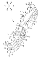
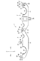
- the perspective view which shows the base member and lid member of a pipe clamp The perspective view which shows the base member and lid member of a pipe clamp Side view showing base member and lid member of pipe clamp
- the perspective view which shows the filler pipe of another form The top view which shows the positional relationship of a base member and the filler pipe of another form Side view showing the positional relationship between the base member and another form of filler pipe
- a pipe clamp (clamp) 1 includes a base member (first member) 2 formed from a resin material and a lid member (first member) rotatably supported by the base member 2. 2 member) 3 and a pin member 4 (see FIG. 6) held by the base member 2 as main components.
- the pipe clamp 1 supports a filler pipe 200 and a breather pipe 201 that are tubular bodies between the base member 2 and the lid member 3, and the base member 2 is attached to the surface of the vehicle body panel 205 as a support member.
- the pipe 200 and the breather pipe 201 are fixed to the vehicle body panel 205.
- the filler pipe 200 is a pipe that connects a fuel filler port and a fuel tank of an automobile, and has a circular cross section in most part. However, in a part in the longitudinal direction, one radial direction (in this embodiment, the left and right direction).
- the narrow direction is referred to as a first radial direction) to form a non-circular narrow portion 203 having a narrow width in the left-right direction.
- the narrow portion 203 has its left and right side portions extending substantially in the vertical direction, but its upper and lower portions maintain an arcuate outer peripheral surface.
- the breather pipe 201 is a pipe provided substantially in parallel with the filler pipe 200 for degassing the fuel tank during refueling, and has a circular cross section.
- the vehicle body panel 205 is a flat panel and is formed with a circular locking hole 206.
- the base member 2 has a main body part 11 extending in the left-right direction, and a first pipe holding part (a first pipe holding part (a first part) for receiving the lower half part of the narrow part 203 of the filler pipe 200 at the upper part of the main body part 11. 1 recess) 12 and a second pipe holding portion 13 for receiving the lower half portion of the breather pipe 201 are recessed.
- Each of the first pipe holding part 12 and the second pipe holding part 13 has a substantially semicircular cross section, extends in the front-rear direction, and communicates with the front surface and the rear surface of the main body part 11.
- the 1st pipe holding part 12 has the convex part 14 which protrudes in the center side of the 1st pipe holding part 12 in the left-right side part of the intermediate part in the front-back direction.
- the width of the first pipe holding portion 12 in the left-right direction of the intermediate portion in the front-rear direction is narrowed.
- the bottom part of the intermediate part in the front-back direction of the 1st pipe holding part 12 is formed in the circumferential surface.
- protrusions 15 and 16 extending in the left-right direction are formed on the surfaces of the first pipe holding part 12 and the second pipe holding part 13. Moreover, the surface of the 1st pipe holding part 12 and the 2nd pipe holding part 13 is cut out by the U-shaped slit, and inward of the 1st pipe holding part 12 or the 2nd pipe holding part 13 in the front-end
- the pressing pieces 17 and 18 having projecting protrusions are formed.
- the pressing pieces 17 and 18 have flexibility and can swing.
- the protrusions 15 and 16 and the pressing pieces 17 and 18 are provided for the purpose of improving the adhesion with the filler pipe 200 and the breather pipe 201.
- the lower portion of the main body 11 has a plurality of hollow portions 22 that are opened downward, and a plurality of ribs 23 are formed so as to partition the respective thin portions 22.
- the lower ends of the ribs 23 are arranged on a virtual plane that is substantially flush with each other, and the main body 11 can be in contact with a flat plane (plate material or the like) at the lower part.
- a pin that is an intermediate portion in the left-right direction of the main body portion 11 and extends between the first pipe holding portion 12 and the second pipe holding portion 13 in the vertical direction and communicates the upper surface and the lower surface of the main body portion.
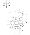
- a hole 25 is formed. As shown in FIG. 4 (FIG. 6), the pin hole 25 has a circular cross section, the upper half portion 26 is coaxially expanded with respect to the lower half portion 27, and faces upward at the boundary portion.
- An annular step 28 is formed.
- the stepped portion 28 is provided with four guide convex portions 30 protruding upward on the bottom surface 29 facing upward at equal intervals (90 ° intervals) in the circumferential direction.
- Each guide convex portion 30 is parallel to the bottom surface 29 from the upper surface of the inclined surface 31 and the inclined surface 31 protruding upward from the bottom surface 29 as it proceeds in the counterclockwise direction in the circumferential direction of the pin hole 25 as viewed from above.
- an upper surface 32 extending in the counterclockwise direction in the circumferential direction.
- An end portion of the upper surface different from the inclined surface 31 side is continuous with the bottom surface 29 through a vertical plane.
- annular groove-shaped hollow portion 35 is formed so as to surround the pin hole 25 coaxially.
- leg pieces 36 projecting downward from the inner peripheral portion of the lower end portion of the pin hole 25 where the lightening portion 35 is formed in the circumferential direction of the pin hole 25. It is formed at equal intervals along.
- Each leg piece 36 functions as a grommet inserted into a locking hole 206 formed in the vehicle body panel 205.
- each leg piece 36 Projections having inclined surfaces facing diagonally upward so as to project toward the central axis side of the pin hole 25 toward the tip (lower end) of the portion of each leg piece 36 facing the central axis side of the pin hole 25 37 is formed, and a claw portion 38 that protrudes toward the central axis of the pin hole 25 is formed on each protrusion 37.
- Each claw part 38 is provided with a check surface facing downward at its lower part.
- Each leg piece 36 has flexibility and can be tilted in the radial direction of the pin hole 25.
- a hinge shaft 50 is provided at the left end of the main body 11.
- the hinge shaft portion 50 includes a shaft support portion 51 that protrudes leftward from the left end surface of the main body portion 11, and a columnar hinge shaft 52 that protrudes forward and rearward from the distal end portion of the shaft support portion 51. .
- connection hole 53 that open upward are recessed in the front and rear sides of the pin hole 25 on the upper surface of the main body 11.
- Each connecting hole 53 is formed such that the opening at the upper end is narrower than the inside. That is, the connecting hole 53 has a locking portion at the upper end opening.
- the inside of the connection hole 53 communicates with the front surface or the rear surface of the base member 2 through the work opening 54.
- a recess 56 that is recessed downward from the top surface is formed at the upper right end of the main body 11.
- Two first elastic claws 57 are arranged in pairs on the bottom surface of the recess 56.
- Each of the first elastic claws 57 has a flexible first protruding piece 58 protruding upward from the bottom of the recess 56 and a downward check surface protruding from the tip of the first protruding piece 58.
- a first claw portion 59 provided.
- the paired first elastic claws 57 are arranged so that the first claw portions 59 of the first elastic claws 57 face each other in the left-right direction.
- first elastic claws 57 that are paired are disposed on the front side and the rear side of the recess 56 so as to be separated from each other. Between the two sets of first elastic claws 57 in the recess 56 in the front-rear direction, a columnar key 60 that protrudes upward is provided.
- the lid member 3 includes a main body 71 that extends in the left-right direction, and a hinge bearing 72 is formed at the right end of the main body 71.
- the hinge bearing portion 72 includes two fork portions 73 that are spaced apart from each other in the front-rear direction from the right end portion of the main body portion 71 and project rightward, and bearing holes 75 provided in the projecting end portions of the fork portions 73. I have.
- the bearing hole 75 is arranged so that its axis extends in the front-rear direction and is coaxial.
- the hinge shaft 52 of the base member 2 is pivotally supported in each bearing hole 75.
- the lid member 3 is rotatably supported by the base member 2 via the hinge portion composed of the bearing hole 75 and the hinge shaft 52 (hinge-coupled).
- a circular through-hole 78 penetrating in the vertical direction is formed in a substantially central portion in the left-right direction at the top of the main body 71.
- the through-hole 78 is a state in which the lid member 3 is closed with respect to the base member 2 (the state shown in FIGS. 6 and 7, and the lid member 3 is positioned above the base member 2). It is arranged to be coaxial.
- a third pipe holding portion 81 that receives the upper half portion of the narrow portion 203 of the filler pipe 200 is disposed on the left side of the through hole 78 in the upper portion of the main body portion 71, and the breather pipe 201 is disposed on the right side.
- the 4th pipe holding part 82 which receives the upper half part is recessedly provided.
- the third pipe holding part 81 and the fourth pipe holding part 82 have a substantially semicircular cross section, and the third pipe holding part 81 and the fourth pipe holding part 82 extend in the front-rear direction.
- the main body 71 communicates with the front surface and the rear surface.
- the third pipe holding portion 81 has convex portions 83 that protrude toward the center of the third pipe holding portion 81 on the left and right sides of the intermediate portion in the front-rear direction.
- the convex portion 83 By the convex portion 83, the width of the third pipe holding portion 81 in the left-right direction of the intermediate portion in the front-rear direction is reduced.
- the bottom part of the intermediate part in the front-back direction of the 3rd pipe holding part 81 is formed in the circumferential surface. In a state where the lid member 3 is closed with respect to the base member 2, the third pipe holding portion 81 faces the first pipe holding portion 12, and the fourth pipe holding portion 82 faces the second pipe holding portion 13.
- the protrusions 85 and 86 extending in the left-right direction are formed on the surfaces of the third pipe holding portion 81 and the fourth pipe holding portion 82. Further, the surface of the third pipe holding portion 81 and the fourth pipe holding portion 82 is cut out by a U-shaped slit communicating with the lower portion of the main body portion 71, and the third pipe holding portion 81 and the fourth pipe are formed at the tip portions thereof. Pressing pieces 87 and 88 having convex portions projecting inward of the pipe holding portion 82 are formed. The pressing pieces 87 and 88 have flexibility and can swing. The protrusions 85 and 86 and the pressing pieces 87 and 88 are provided for the purpose of improving the adhesion with the filler pipe 200 and the breather pipe 201.
- Two connecting pieces 91 project upward from the front and rear of the through-hole 78 in the upper part of the main body 71.
- a claw portion 92 cut out by a U-shaped slit is formed on the side portion of each connecting piece 91.
- the claw portion 92 is provided so as to be tiltable with respect to the connecting piece 91, and can be projected and retracted with respect to the connecting piece 91 by elastic deformation.
- Two second elastic claws 93 are provided at the left end of the upper portion of the main body 71 so as to be separated from each other in the front-rear direction.
- Each of the second elastic claws 93 has a flexible second projecting piece portion 94 that extends upward, and protrudes left and right from the tip of the second projecting piece portion 94 to form two check surfaces.
- an arrowhead-shaped second claw portion 95 is provided in the portion between the two second elastic claws 93 in the front-rear direction.
- a gap is formed between the wall 98 and each second elastic claw 93, and the wall 98 and each second elastic claw 93 are not connected.
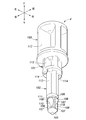
- the pin member 4 includes a cylindrical intermediate shaft portion 101, a small-diameter shaft portion 102 having a smaller diameter than the intermediate shaft portion 101 provided coaxially at one end of the intermediate shaft portion 101, and an intermediate shaft portion. And a large-diameter shaft portion 103 provided on the other end side of 101.
- the outer diameter of the small diameter shaft portion 102 is formed smaller than the inner diameter of the lower half portion 27 of the pin hole 25.
- the outer diameter of the intermediate shaft portion 101 is smaller than the inner diameter of the upper half portion 26 of the pin hole 25 and larger than the inner diameter of the lower half portion 27.
- the outer diameter of the large-diameter shaft portion 103 is larger than the inner diameter of the upper half portion 26 and smaller than the inner diameter of the through hole 78.
- the small diameter shaft portion 102 includes a conical tip portion 105.
- Four concave portions 106 formed at equal intervals in the circumferential direction are provided above the proximal end portion 105 of the small diameter shaft portion 102, and a partition wall 107 is provided between the adjacent concave portions 106.
- a locking protrusion 108 extending in the circumferential direction is provided above each recess 106 of the small-diameter shaft 102 (proximal end side).
- the locking ridge 108 is formed so that its circumferential length is shorter than the circumferential length of the recess 106, and a portion between the adjacent locking ridges 108 in the circumferential direction (positioned above the partition wall 107).
- the valley portion 109 in which the circumferential surface of the small-diameter shaft portion 102 is exposed is formed in the portion).
- the portion that becomes the upper side wall of each recess 106 is formed on the inclined surface 110 so as to smoothly continue to the protruding end of the locking protrusion 108.
- a restriction wall 111 extending in the circumferential direction of the small-diameter shaft portion 102 extends from a portion of the small-diameter shaft portion 102 which is spaced upward from the locking protrusion 108.
- Each convex portion 114 projectsing downward are formed on the lower surface of the intermediate shaft portion 101.
- Each convex portion 114 is formed in the same shape, and is provided at a symmetrical position with the axis of the intermediate shaft portion 101 as the axis of symmetry.
- a tool hole 116 that can be engaged with a tool (for example, a flat-blade screwdriver) is formed on the upper end surface of the large-diameter shaft portion 103.
- a thinning portion 112 is formed at appropriate positions of the intermediate shaft portion 101, the small diameter shaft portion 102, and the large diameter shaft portion 103.
- the pin member 4 is inserted into the upper end side of the pin hole 25 from the distal end portion 105 in a state where the lid member 3 is closed with respect to the base member 2.
- a flexible annular seal member 121 is attached to the outer peripheral portion of the intermediate shaft portion 101 of the pin member 4.
- An annular sealing member 122 having flexibility is attached to the outer peripheral portion of each leg piece portion 36.
- the lid member 3 is opened with respect to the base member 2, the narrow portion 203 of the filler pipe 200 is disposed in the first pipe holding portion 12 of the base member 2, and the breather pipe 201 is held in the second pipe.
- the lower half portion of the narrow portion 203 is disposed in the first pipe holding portion 12 so that the first radial direction, which is the narrow radial direction of the narrow portion 203, coincides with the left-right direction.
- the left and right side portions of the lower half of the narrow portion 203 abut against the convex portion 14 of the first pipe holding portion 12, and the filler pipe 200 is supported so as not to rotate with respect to the base member 2.
- the lid member 3 is rotated with respect to the base member 2 so that the upper part of the base member 2 is covered with the lid member 3.
- the upper half of the filler pipe 200 is disposed in the third pipe holding portion 81 and the upper half of the breather pipe 201 is disposed in the fourth pipe holding portion 82.
- the left and right side portions of the upper half of the narrow portion 203 abut on the convex portion 83 of the third pipe holding portion 81.
- the first claw portion 59 of the first elastic claw 57 of the base member 2 and the second claw portion 95 of the second elastic claw 93 of the lid member 3 are hooked (engaged) with each other and the lid member 3 is connected.
- the piece 91 enters the connection hole 53 of the base member 2, and the claw portion 92 is caught in the connection hole 53.
- the cover member 3 is fixed with respect to the base member 2 (refer FIG. 6).
- the pin member 4 is inserted into the pin hole 25.
- the tip end portion 105 of the pin member 4 comes into contact with the inclined surface of the protruding portion 37 of each leg piece portion 36 and the claw portion 38.
- each leg piece portion 36 is elastically deformed outward in the radial direction of the pin hole 25, and the tip portion 105 passes through the claw portion 38.
- each leg piece portion 36 tries to return to the initial state by a restoring force, and the protruding portion 37 and the claw portion 38 enter into the concave portion 106 (see FIG. 6). In this manner, the pin member 4 is held in the pin hole 25 by the protrusion 37 and the claw 38 being locked in the recess 106.
- the four leg pieces 36 are inserted into the locking holes 206 of the vehicle body panel 205, and the lower part of the base member 2 (the lower end of each rib 23) is brought into contact with the surface of the vehicle body panel 205.
- the large-diameter shaft portion 103 of the pin member 4 is pressed toward the base member 2 side with a finger or a tool.
- the pin member 4 moves to the distal end side of the leg piece portion 36, the projecting portion 37 and the claw portion 38 of the leg piece portion 36 are pressed against the inclined surface 110 of the pin member 4, and the distal end portion of each leg piece portion 36 is a pin hole. 25 is displaced outward in the radial direction.
- the claw portion 38 slides on the inclined surface 110 and rides over the locking protrusion 108 upward. Thereafter, the convex portion 114 of the pin member 4 comes into contact with the bottom surface 29 of the step portion 28, and the movement of the pin member 4 with respect to the leg piece portion 36 is restricted. In this state, as shown in FIG. 7, the protruding portion 37 and the claw portion 38 are detached from the concave portion 106, and the claw portion 38 is in contact with the outer peripheral surface of the small-diameter shaft portion 102. Is maintained in a state of spreading outward in the radial direction of the pin hole 25.
- leg piece part 36 is latched by the latching hole 206, and the detachment
- the claw portion 38 is locked to the locking protrusion 108, the pin member 4 is prevented from being removed from the pin hole 25.
- the large-diameter shaft portion 103 of the pin member 4 seals the upper end portion of the pin hole 25 via the seal member 121, and the lower end peripheral portion of the pin hole 25 of the base member 2 is engaged via the seal member 122.
- the periphery of the stop hole 206 is sealed.
- the locking hole 206 is sealed in a watertight manner.
- a tool for example, a Phillips screwdriver
- the pin member 4 is rotated counterclockwise as viewed from above.
- the claw portions 38 of the leg pieces 36 are separated from the positions facing the locking protrusions 108 of the pin member 4 and are opposed to the valleys 109.
- the convex portion 114 of the pin member 4 slides on the step portion 28 from the bottom surface 29 through the inclined surface 31 to the upper surface 32, and the pin member 4 is displaced upward with respect to the base member 2.
- the first elastic claws 57 facing each other in the left-right direction are widened with a finger, a tool, etc., and the hooked state between the first claw portion 59 of the first elastic claw 57 and the second claw portion 95 of the second elastic claw 93 is released.
- the claw portion 92 of the connecting piece 91 is immersed with a finger or a tool through the work opening 54 to release the engagement between the connecting piece 91 and the connecting hole 53. Accordingly, the lid member 3 can be opened from the base member 2, and the filler pipe 200 and the breather pipe 201 can be detached from the pipe clamp 1.
- the pipe clamp 1 configured as described above has a first direction (left-right direction) which is a reduced direction of the narrow portion 203 with respect to a direction (up-down direction) in which the base member 2 and the lid member 3 face each other.
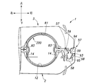
- the narrow portion 203 is supported by the first pipe holding portion 12 and the third pipe holding portion 81 so that the two are orthogonal to each other. Therefore, as shown in FIG. 8, the filler pipe 200 is displaced in the thrust direction (forward), and another wide portion located next to the narrow portion 203 of the filler pipe 200 is the first pipe holding portion 12.
- the first pipe holding part 12 and the third pipe holding part 81 receive a load so as to expand from the filler pipe 200 in the left-right direction, and directly from the filler pipe 200. There is no load in the vertical direction. Therefore, the load for expanding the base member 2 and the lid member 3 in the vertical direction is reduced, and the catch between the first elastic claw 57 and the second elastic claw 93 is easily maintained.
- the filler pipe 200 is a thrust direction.
- the load applied to the first pipe holding part 12 and the third pipe holding part 81 is applied from a position close to the middle part in the front-rear direction, and the base member 2 and the lid member 3 are moved in the front-rear direction. It is possible to prevent twisting.
- the fitting between the key 60 and the fitting hole 97 prevents the base member 2 and the lid member 3 from moving relative to each other in the left-right direction and the front-rear direction (position shift).
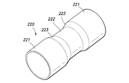
- the pipe clamp 1 having the above configuration can also support a filler pipe 220 having a shape as shown in FIG. 10 instead of the pipe crushed in the first radial direction like the filler pipe 200.
- the filler pipe 220 includes a large-diameter portion 221 having a circular cross section that forms most of the tube, and a cross-section that is provided coaxially with the large-diameter portion 221 in a part in the longitudinal direction of the tube and has a smaller diameter than the large-diameter portion 221.
- a circular narrow portion 222 and a truncated cone-shaped tapered portion that is provided between both ends of the narrow portion 222 and the large diameter portion 221 and gradually increases in diameter from the narrow portion 222 to the large diameter portion 221. 223.
- the narrow portion 222 differs from the narrow portion 203 in that the width is narrow not only in the first radial direction but over the entire circumference.
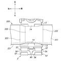
- the diameter of the large diameter part 221 is smaller than the distance between the bottom surfaces of the first pipe holding part 12 and the third pipe holding part 81 and larger than the distance between the convex parts 14 and 83.
- the diameter of the narrow portion 222 may be equal to or smaller than the distance between the convex portions 14 and 83.
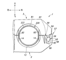
- FIG. 12 shows a cross section of the filler pipe 220 cut at the narrow portion 222.
- a gap is formed between the upper and lower portions of the narrow portion 222 and the bottom surfaces of the first pipe holding portion 12 and the third pipe holding portion 81, and the filler pipe 220 is connected to the first pipe holding portion 12 and the third pipe holding portion. Within 81, it can be displaced in the vertical direction.
- the tapered portion 223 of the filler pipe 220 presses the convex portions 14 and 83 so as to expand in the left-right direction. Since the diameter of the large diameter portion 221 is smaller than the distance between the bottom surfaces of the first pipe holding portion 12 and the third pipe holding portion 81, the filler pipe 220 is a portion other than the convex portions 14 and 83 at the first pipe holding portion. 12 and the 3rd pipe holding part 81 are not pressed, and the 1st pipe holding part 12 and the 3rd pipe holding part 81 do not receive a load from the filler pipe 220 directly to an up-down direction.
- Second elastic claw, 94 Second projecting piece , 95 ... second claw part, 97 ... fitting hole, 200, 220 ... filler pipe (pipe), 201 ... breather pipe, 203, 222 ... narrow part, 205 ... body panel (support member), 206 ... Blind hole
Landscapes
- Engineering & Computer Science (AREA)
- General Engineering & Computer Science (AREA)
- Mechanical Engineering (AREA)
- Supports For Pipes And Cables (AREA)
- Insertion Pins And Rivets (AREA)
Abstract
Description
Claims (6)
- 長手方向における一部に少なくとも第1の径方向に幅が狭められた幅狭部を有する管を、支持部材に取り付けるためのクランプであって、
第1凹部を有し、前記支持部材に結合する第1部材と、
基端が前記第1部材にヒンジ結合し、先端が前記第1部材に選択的に係合すると共に、前記先端が前記第1部材に係合した状態において、前記第1凹部に対向して前記第1凹部と共に前記幅狭部を受容する収容部を画成する第2凹部を有する第2部材と
を備え、
前記第1凹部及び前記第2凹部は、前記第1部材及び前記第2部材の対向方向に対して前記第1の径方向が直交する姿勢で、前記幅狭部を支持し、前記幅狭部の前記第1の径方向における部分に当接することを特徴とするクランプ。 - 前記第1凹部は、前記管の長手方向に延在して前記第1部材の両端面に連通し、
前記第2凹部は、前記管の長手方向に延在して前記第2部材の両端面に連通し、
前記第1凹部及び前記第2凹部は、延在方向における両端部において、前記幅狭部と空隙を介して対向し、延在方向における中間部において、前記幅狭部の前記第1の径方向における部分に当接する形状に形成されていることを特徴とする請求項1に記載のクランプ。 - 前記第1部材は、前記第2部材の先端に対向する部分に前記第2部材側へと突設された可撓性の第1突片部及び前記第1突片部の先端に突設された第1爪部を備えた第1弾性爪を有し、
前記第2部材は、前記第2部材の先端に前記第1部材側へと突設された可撓性の第2突片部及び前記第2突片部の先端に突設された第2爪部を備えた第2弾性爪を有し、
前記第1弾性爪の前記第1爪部と前記第2弾性爪の第2爪部とが、選択的に互いに引っ掛かることによって前記第2部材が前記第1部材に選択的に係合されることを特徴とする請求項1又は請求項2に記載のクランプ。 - 前記第1部材は、前記管の長手方向に対応する方向に沿って前記第1弾性爪を複数有し、
前記第2部材は、複数の前記第1弾性爪に対応する部分に前記第2弾性爪を複数有することを特徴とする請求項3に記載のクランプ。 - 前記第2爪部が前記第2突片部の先端から相反する2方向に突出して2つの逆止面を有し、
前記第1弾性爪は、1つの前記第2弾性爪に対して2つで挟むように設けられ、2つの第1爪部は前記第2爪部の2つの逆止面にそれぞれ引っ掛かることを特徴とする請求項3又は請求項4に記載のクランプ。 - 前記第2部材の先端部及び前記先端部に対向する前記第1部材の部分の一方にはキーが突設され、他方には前記キーが嵌合する嵌合孔が形成されていることを特徴とする請求項1~請求項5のいずれか1つの項に記載のクランプ。
Priority Applications (2)
| Application Number | Priority Date | Filing Date | Title |
|---|---|---|---|
| US14/113,112 US9080698B2 (en) | 2011-04-28 | 2012-04-09 | Clamp |
| CN201280032536.0A CN103635731B (zh) | 2011-04-28 | 2012-04-09 | 夹持件 |
Applications Claiming Priority (2)
| Application Number | Priority Date | Filing Date | Title |
|---|---|---|---|
| JP2011-100412 | 2011-04-28 | ||
| JP2011100412A JP5791953B2 (ja) | 2011-04-28 | 2011-04-28 | クランプ |
Publications (1)
| Publication Number | Publication Date |
|---|---|
| WO2012147289A1 true WO2012147289A1 (ja) | 2012-11-01 |
Family
ID=47071823
Family Applications (1)
| Application Number | Title | Priority Date | Filing Date |
|---|---|---|---|
| PCT/JP2012/002462 Ceased WO2012147289A1 (ja) | 2011-04-28 | 2012-04-09 | クランプ |
Country Status (4)
| Country | Link |
|---|---|
| US (1) | US9080698B2 (ja) |
| JP (1) | JP5791953B2 (ja) |
| CN (1) | CN103635731B (ja) |
| WO (1) | WO2012147289A1 (ja) |
Cited By (1)
| Publication number | Priority date | Publication date | Assignee | Title |
|---|---|---|---|---|
| JP2016098495A (ja) * | 2014-11-19 | 2016-05-30 | 博登 脇坂 | 建築構造材及び建築物 |
Families Citing this family (34)
| Publication number | Priority date | Publication date | Assignee | Title |
|---|---|---|---|---|
| HRP20160956T1 (hr) * | 2011-10-21 | 2016-10-07 | Q-Clip B.V. | Stezaljka za cijev |
| JP6048729B2 (ja) * | 2012-08-31 | 2016-12-21 | ポップリベット・ファスナー株式会社 | 防振クランプ |
| JP5913008B2 (ja) * | 2012-09-03 | 2016-04-27 | 矢崎総業株式会社 | ハーネス保護チューブのクランプ構造 |
| JP6106459B2 (ja) | 2013-02-26 | 2017-03-29 | 株式会社ケーヒン | 車両用空気調和装置 |
| US20150285408A1 (en) * | 2014-04-07 | 2015-10-08 | Superior Tray Systems Inc. | Cable pass through sealing systems |
| ITUB20154200A1 (it) * | 2015-10-07 | 2017-04-07 | Fi Mo Tec Spa | Dispositivo di tipo migliorato per il fissaggio di cavi, tubi ed altri corpi lungiformi in genere aventi diametro differenziato |
| US10948107B2 (en) * | 2015-10-30 | 2021-03-16 | Commscope Technologies Llc | Hanger for mounting cables |
| NL2015917B1 (en) * | 2015-12-07 | 2017-06-28 | Walraven Holding Bv J Van | Pipe clamp for a range of pipe diameters. |
| US10411399B2 (en) * | 2016-04-07 | 2019-09-10 | Signify Holding B.V. | Electrical cable retention |
| JP6772624B2 (ja) * | 2016-07-28 | 2020-10-21 | アイシン精機株式会社 | 車両開閉体操作装置 |
| US11060637B2 (en) * | 2016-12-01 | 2021-07-13 | Ckd Corporation | Coupling member, fluid-device connecting jig, and fluid-device connecting structure |
| US10094491B1 (en) * | 2017-10-17 | 2018-10-09 | Wanho T Manufacturing Co., Ltd. | Organizing device for cable and wire |
| US10464505B2 (en) * | 2017-10-20 | 2019-11-05 | GM Global Technology Operations LLC | Cable retention member |
| JP6951663B2 (ja) * | 2017-12-26 | 2021-10-20 | 住友電装株式会社 | コネクタ |
| FR3077113B1 (fr) * | 2018-01-22 | 2019-12-13 | Autotube Aktiebolag | Support articule de serrage d'au moins un article tubulaire |
| JP6924731B2 (ja) * | 2018-07-26 | 2021-08-25 | 株式会社ニフコ | ヒンジ構造 |
| US10704710B2 (en) | 2018-11-20 | 2020-07-07 | The Boeing Company | Easy lock P-clamp |
| EP3680531A1 (fr) * | 2019-01-14 | 2020-07-15 | Autotube AB | Support articule de serrage d'au moins un article tubulaire |
| JP7120094B2 (ja) * | 2019-03-15 | 2022-08-17 | 豊田合成株式会社 | 車両用パイプ保持具 |
| WO2020240624A1 (ja) * | 2019-05-24 | 2020-12-03 | 日栄インテック株式会社 | 配管支持具 |
| CN110811207A (zh) * | 2019-12-02 | 2020-02-21 | 上海菁筑贸易有限公司 | 一种床架端套弧形结构 |
| CN110840148A (zh) * | 2019-12-02 | 2020-02-28 | 上海菁筑贸易有限公司 | 一种床架弹性支撑装置 |
| JP7471909B2 (ja) * | 2020-05-15 | 2024-04-22 | タカラスタンダード株式会社 | 給水給湯管支持具及び給水給湯管固定構造 |
| CN111729946B (zh) * | 2020-07-27 | 2020-11-10 | 宁波米锐汽车配件技术有限公司 | 一种汽车橡胶减震器金属钢管用矫直装置 |
| DE102021112778A1 (de) | 2021-05-18 | 2022-11-24 | Bayerische Motoren Werke Aktiengesellschaft | Halter zur Aufnahme einer Leitung, Befestigungsanordnung zur Befestigung einer Leitung an einem Kraftfahrzeug und Verfahren zur Befestigung einer Leitung an einem Kraftfahrzeug |
| MX2023014024A (es) * | 2021-08-02 | 2023-12-12 | Mitsubishi Electric Corp | Unidad de intercambio de calor. |
| EP4131687A1 (en) | 2021-08-06 | 2023-02-08 | HellermannTyton GmbH | Edge clip |
| CN113483157B (zh) * | 2021-08-06 | 2024-10-01 | 海尔曼太通(无锡)电器配件有限公司 | 一种快速拆装管夹 |
| US12435818B2 (en) * | 2022-01-05 | 2025-10-07 | Aptiv Technologies AG | Retainer clip assembly |
| US11959571B2 (en) | 2022-08-18 | 2024-04-16 | Panduit Corp. | Cable clamp with adjustment latches |
| FR3149663A1 (fr) | 2023-06-12 | 2024-12-13 | Psa Automobiles Sa | Dispositif de bridage ajustable de câbles |
| US12372169B2 (en) * | 2023-09-22 | 2025-07-29 | Paccar Inc | Retention clamp |
| KR102770505B1 (ko) * | 2023-12-12 | 2025-02-18 | 김국환 | 수납선반 결합장치 |
| US12483013B2 (en) | 2024-05-08 | 2025-11-25 | Panduit Corp. | High voltage cable cleat |
Citations (5)
| Publication number | Priority date | Publication date | Assignee | Title |
|---|---|---|---|---|
| JPH0436191U (ja) * | 1990-07-23 | 1992-03-26 | ||
| JPH0674664U (ja) * | 1993-03-31 | 1994-10-21 | 古河電気工業株式会社 | 管固定具 |
| JP2008291873A (ja) * | 2007-05-23 | 2008-12-04 | Nifco Inc | パイプ保持具 |
| JP2009192002A (ja) * | 2008-02-15 | 2009-08-27 | Toyota Auto Body Co Ltd | 結束対象物用のクランプ |
| JP2011133003A (ja) * | 2009-12-24 | 2011-07-07 | Toyoda Gosei Co Ltd | パイプ保持具 |
Family Cites Families (8)
| Publication number | Priority date | Publication date | Assignee | Title |
|---|---|---|---|---|
| JPS6329982U (ja) | 1986-08-13 | 1988-02-27 | ||
| JPH0416007Y2 (ja) * | 1987-09-21 | 1992-04-10 | ||
| JP2005155749A (ja) | 2003-11-25 | 2005-06-16 | Nifco Inc | パイプクランプ |
| US20050184524A1 (en) * | 2004-02-23 | 2005-08-25 | Stravitz David M. | Quick-connect/quick-disconnect conduit connectors |
| DE202006006347U1 (de) * | 2006-04-19 | 2006-06-14 | Veritas Ag | Halteeinrichtung für mindestens eine Leitung |
| US20090140108A1 (en) | 2007-12-03 | 2009-06-04 | International Engine Intellectual Property Company, Llc | Multiple tube clip |
| JP5602460B2 (ja) * | 2010-03-05 | 2014-10-08 | 株式会社ニフコ | クランプ |
| FR2962513B1 (fr) * | 2010-07-09 | 2012-08-10 | Trw Automotive Elect & Components Gmbh | Composant pour un clip de fixation et clip de fixation |
-
2011
- 2011-04-28 JP JP2011100412A patent/JP5791953B2/ja not_active Expired - Fee Related
-
2012
- 2012-04-09 CN CN201280032536.0A patent/CN103635731B/zh active Active
- 2012-04-09 WO PCT/JP2012/002462 patent/WO2012147289A1/ja not_active Ceased
- 2012-04-09 US US14/113,112 patent/US9080698B2/en active Active
Patent Citations (5)
| Publication number | Priority date | Publication date | Assignee | Title |
|---|---|---|---|---|
| JPH0436191U (ja) * | 1990-07-23 | 1992-03-26 | ||
| JPH0674664U (ja) * | 1993-03-31 | 1994-10-21 | 古河電気工業株式会社 | 管固定具 |
| JP2008291873A (ja) * | 2007-05-23 | 2008-12-04 | Nifco Inc | パイプ保持具 |
| JP2009192002A (ja) * | 2008-02-15 | 2009-08-27 | Toyota Auto Body Co Ltd | 結束対象物用のクランプ |
| JP2011133003A (ja) * | 2009-12-24 | 2011-07-07 | Toyoda Gosei Co Ltd | パイプ保持具 |
Cited By (1)
| Publication number | Priority date | Publication date | Assignee | Title |
|---|---|---|---|---|
| JP2016098495A (ja) * | 2014-11-19 | 2016-05-30 | 博登 脇坂 | 建築構造材及び建築物 |
Also Published As
| Publication number | Publication date |
|---|---|
| US20140091182A1 (en) | 2014-04-03 |
| US9080698B2 (en) | 2015-07-14 |
| JP2012233491A (ja) | 2012-11-29 |
| JP5791953B2 (ja) | 2015-10-07 |
| CN103635731A (zh) | 2014-03-12 |
| CN103635731B (zh) | 2016-04-06 |
Similar Documents
| Publication | Publication Date | Title |
|---|---|---|
| JP5791953B2 (ja) | クランプ | |
| JP5602460B2 (ja) | クランプ | |
| JP5602511B2 (ja) | クランプ | |
| JP5118066B2 (ja) | パネルの穴に押し込むスナップ式の係合部を備える締結具 | |
| JP2007239991A (ja) | トリムリテーナ | |
| US10967808B2 (en) | Interior cover mount assembly | |
| JP4545711B2 (ja) | クリップ | |
| JP2010151179A (ja) | 車両用クッションクリップ | |
| US20150102616A1 (en) | Bumper attachment structure | |
| JP2010283965A (ja) | コルゲートクランプ | |
| JP2009079751A (ja) | 雌ねじ用穴塞ぎプラグ | |
| JP7035061B2 (ja) | クリップ | |
| CN108131495B (zh) | 导管保持夹组件 | |
| JP2015214181A (ja) | ワイパブレードの連結構造 | |
| WO2014017374A1 (ja) | バッテリ固定保持用のクランプ構造 | |
| JP2004068830A (ja) | スタッド係止具 | |
| JP2007198474A (ja) | 線条体の保持具 | |
| JP5065927B2 (ja) | グロメット | |
| JP6623742B2 (ja) | クリップおよびピラーガーニッシュ取付構造 | |
| JP2008298154A (ja) | 配線・配管材固定具 | |
| JP2013218382A (ja) | 連結ピン組付補助具 | |
| JP2014214826A (ja) | キャップ | |
| JP2010276031A (ja) | 部品の取付装置 | |
| JP5240446B2 (ja) | カウルトップガーニッシュ | |
| CN211592235U (zh) | 配管临时固定结构 |
Legal Events
| Date | Code | Title | Description |
|---|---|---|---|
| WWE | Wipo information: entry into national phase |
Ref document number: 201280032536.0 Country of ref document: CN |
|
| 121 | Ep: the epo has been informed by wipo that ep was designated in this application |
Ref document number: 12776992 Country of ref document: EP Kind code of ref document: A1 |
|
| NENP | Non-entry into the national phase |
Ref country code: DE |
|
| WWE | Wipo information: entry into national phase |
Ref document number: 14113112 Country of ref document: US |
|
| 122 | Ep: pct application non-entry in european phase |
Ref document number: 12776992 Country of ref document: EP Kind code of ref document: A1 |