EP4131687A1 - Edge clip - Google Patents
Edge clip Download PDFInfo
- Publication number
- EP4131687A1 EP4131687A1 EP21190204.4A EP21190204A EP4131687A1 EP 4131687 A1 EP4131687 A1 EP 4131687A1 EP 21190204 A EP21190204 A EP 21190204A EP 4131687 A1 EP4131687 A1 EP 4131687A1
- Authority
- EP
- European Patent Office
- Prior art keywords
- edge
- legs
- gap
- sidewalls
- component
- Prior art date
- Legal status (The legal status is an assumption and is not a legal conclusion. Google has not performed a legal analysis and makes no representation as to the accuracy of the status listed.)
- Pending
Links
- 238000003780 insertion Methods 0.000 claims abstract description 33
- 230000037431 insertion Effects 0.000 claims abstract description 33
- 238000001746 injection moulding Methods 0.000 claims description 9
- 238000000034 method Methods 0.000 claims description 6
- 238000000465 moulding Methods 0.000 claims 1
- 210000002414 leg Anatomy 0.000 description 98
- 239000002184 metal Substances 0.000 description 10
- 210000002683 foot Anatomy 0.000 description 4
- 239000003365 glass fiber Substances 0.000 description 4
- 239000004033 plastic Substances 0.000 description 4
- 229920003023 plastic Polymers 0.000 description 4
- 239000013256 coordination polymer Substances 0.000 description 3
- 239000000243 solution Substances 0.000 description 3
- 210000002105 tongue Anatomy 0.000 description 3
- 239000004952 Polyamide Substances 0.000 description 2
- 238000005452 bending Methods 0.000 description 2
- 210000000078 claw Anatomy 0.000 description 2
- 239000000463 material Substances 0.000 description 2
- 229920002647 polyamide Polymers 0.000 description 2
- 229920002292 Nylon 6 Polymers 0.000 description 1
- 229920002302 Nylon 6,6 Polymers 0.000 description 1
- 229920010540 PA6 GF30 Polymers 0.000 description 1
- 229920006914 PA6-GF15 Polymers 0.000 description 1
- 229920006920 PA6-GF30 Polymers 0.000 description 1
- 229920009788 PA66 GF30 Polymers 0.000 description 1
- 229920006507 PA66-GF15 Polymers 0.000 description 1
- 229920006497 PA66-GF30 Polymers 0.000 description 1
- 210000000988 bone and bone Anatomy 0.000 description 1
- 230000007797 corrosion Effects 0.000 description 1
- 238000005260 corrosion Methods 0.000 description 1
- 230000006378 damage Effects 0.000 description 1
- 230000001419 dependent effect Effects 0.000 description 1
- 210000003127 knee Anatomy 0.000 description 1
- 230000007774 longterm Effects 0.000 description 1
- 238000004519 manufacturing process Methods 0.000 description 1
- 230000007935 neutral effect Effects 0.000 description 1
- 229920002635 polyurethane Polymers 0.000 description 1
- 239000004814 polyurethane Substances 0.000 description 1
- 230000000284 resting effect Effects 0.000 description 1
- 229920001169 thermoplastic Polymers 0.000 description 1
- 229920002725 thermoplastic elastomer Polymers 0.000 description 1
- 239000004416 thermosoftening plastic Substances 0.000 description 1
- 210000003371 toe Anatomy 0.000 description 1
Images


Classifications
-
- H—ELECTRICITY
- H02—GENERATION; CONVERSION OR DISTRIBUTION OF ELECTRIC POWER
- H02G—INSTALLATION OF ELECTRIC CABLES OR LINES, OR OF COMBINED OPTICAL AND ELECTRIC CABLES OR LINES
- H02G3/00—Installations of electric cables or lines or protective tubing therefor in or on buildings, equivalent structures or vehicles
- H02G3/30—Installations of cables or lines on walls, floors or ceilings
- H02G3/32—Installations of cables or lines on walls, floors or ceilings using mounting clamps
-
- F—MECHANICAL ENGINEERING; LIGHTING; HEATING; WEAPONS; BLASTING
- F16—ENGINEERING ELEMENTS AND UNITS; GENERAL MEASURES FOR PRODUCING AND MAINTAINING EFFECTIVE FUNCTIONING OF MACHINES OR INSTALLATIONS; THERMAL INSULATION IN GENERAL
- F16B—DEVICES FOR FASTENING OR SECURING CONSTRUCTIONAL ELEMENTS OR MACHINE PARTS TOGETHER, e.g. NAILS, BOLTS, CIRCLIPS, CLAMPS, CLIPS OR WEDGES; JOINTS OR JOINTING
- F16B2/00—Friction-grip releasable fastenings
- F16B2/005—Means to increase the friction-coefficient
-
- B—PERFORMING OPERATIONS; TRANSPORTING
- B29—WORKING OF PLASTICS; WORKING OF SUBSTANCES IN A PLASTIC STATE IN GENERAL
- B29C—SHAPING OR JOINING OF PLASTICS; SHAPING OF MATERIAL IN A PLASTIC STATE, NOT OTHERWISE PROVIDED FOR; AFTER-TREATMENT OF THE SHAPED PRODUCTS, e.g. REPAIRING
- B29C45/00—Injection moulding, i.e. forcing the required volume of moulding material through a nozzle into a closed mould; Apparatus therefor
- B29C45/16—Making multilayered or multicoloured articles
- B29C45/1676—Making multilayered or multicoloured articles using a soft material and a rigid material, e.g. making articles with a sealing part
-
- F—MECHANICAL ENGINEERING; LIGHTING; HEATING; WEAPONS; BLASTING
- F16—ENGINEERING ELEMENTS AND UNITS; GENERAL MEASURES FOR PRODUCING AND MAINTAINING EFFECTIVE FUNCTIONING OF MACHINES OR INSTALLATIONS; THERMAL INSULATION IN GENERAL
- F16B—DEVICES FOR FASTENING OR SECURING CONSTRUCTIONAL ELEMENTS OR MACHINE PARTS TOGETHER, e.g. NAILS, BOLTS, CIRCLIPS, CLAMPS, CLIPS OR WEDGES; JOINTS OR JOINTING
- F16B2/00—Friction-grip releasable fastenings
- F16B2/20—Clips, i.e. with gripping action effected solely by the inherent resistance to deformation of the material of the fastening
- F16B2/22—Clips, i.e. with gripping action effected solely by the inherent resistance to deformation of the material of the fastening of resilient material, e.g. rubbery material
-
- F—MECHANICAL ENGINEERING; LIGHTING; HEATING; WEAPONS; BLASTING
- F16—ENGINEERING ELEMENTS AND UNITS; GENERAL MEASURES FOR PRODUCING AND MAINTAINING EFFECTIVE FUNCTIONING OF MACHINES OR INSTALLATIONS; THERMAL INSULATION IN GENERAL
- F16B—DEVICES FOR FASTENING OR SECURING CONSTRUCTIONAL ELEMENTS OR MACHINE PARTS TOGETHER, e.g. NAILS, BOLTS, CIRCLIPS, CLAMPS, CLIPS OR WEDGES; JOINTS OR JOINTING
- F16B5/00—Joining sheets or plates, e.g. panels, to one another or to strips or bars parallel to them
- F16B5/06—Joining sheets or plates, e.g. panels, to one another or to strips or bars parallel to them by means of clamps or clips
- F16B5/0685—Joining sheets or plates to strips or bars
-
- F—MECHANICAL ENGINEERING; LIGHTING; HEATING; WEAPONS; BLASTING
- F16—ENGINEERING ELEMENTS AND UNITS; GENERAL MEASURES FOR PRODUCING AND MAINTAINING EFFECTIVE FUNCTIONING OF MACHINES OR INSTALLATIONS; THERMAL INSULATION IN GENERAL
- F16B—DEVICES FOR FASTENING OR SECURING CONSTRUCTIONAL ELEMENTS OR MACHINE PARTS TOGETHER, e.g. NAILS, BOLTS, CIRCLIPS, CLAMPS, CLIPS OR WEDGES; JOINTS OR JOINTING
- F16B5/00—Joining sheets or plates, e.g. panels, to one another or to strips or bars parallel to them
- F16B5/12—Fastening strips or bars to sheets or plates, e.g. rubber strips, decorative strips for motor vehicles, by means of clips
- F16B5/128—Fastening strips or bars to sheets or plates, e.g. rubber strips, decorative strips for motor vehicles, by means of clips a strip with a C-or U-shaped cross section being fastened to a plate such that the fastening means remain invisible, e.g. the fastening being completely enclosed by the strip
Definitions
- the present disclosure relates to an edge clip for attaching an item to an edge, in particular for attaching a cable tie to an edge, comprising a first part with a holding fixture for the item, such as an eye for the cable tie, and a second part with two sidewalls, forming a gap between the two sidewalls, wherein when the edge clip is plugged/mounted onto the edge, the edge is introduced into the gap in an insertion direction, where the first part and sidewalls are formed integrally with each other and where the top part and at least a part of the sidewalls are formed of a hard component.
- edge clips In order to attach one or more items to an edge, several types of edge clips are known from the state-of-the-art.
- An exemplary solution is shown in US 9 328 756 B2 , which describes a fixing device for cables with at least an edge clip part for mounting the fixing device on an edge of a base part.
- the edge clip part includes a plug-on gap into which the edge is introduced when plugging the edge clip part onto the edge.
- a metal part is inserted in the edge clip part in order to reinforce the edge clip part.
- the metal part can include one or several holding tongues, which protrude into the plug-on gap and rest against the edge when the fixing device is mounted.
- Similar solutions are shown in JP 6 546 699 B2 , EP 3 091 977 B1 or US 7 819 365 B2 and US 7 725 991 B2 .
- EP 3 263 916 B1 shows a device for fastening an elongated object to a ribshaped support, in which an approximately U-shaped bracket made of a mechanically stable material is used, which bracket has two legs, where on the ends of the legs of the brackets in each case a plate pivotable about a rotational point is arranged, which both extend in a resting position approximately at a right angle to the direction of the legs and which are connected to each other by a bendable connecting element. Then, the two plates, when the bracket is pushed onto the support, can be pivoted by the same about the rotational point in such a manner that in an end position, they each abut on a side of the support against the same, thereby fastening the device on the support.
- an edge clip for attaching an item to an edge of an object in particular for attaching a cable tie to an edge, comprising a first part, which may also be referred to as top part, with a holding fixture for the item, for instance an eye for the cable tie, and a second part, which may be referred to as bottom part, with two sidewalls, forming a gap between the two sidewalls.
- a first part which may also be referred to as top part
- a holding fixture for the item for instance an eye for the cable tie
- a second part which may be referred to as bottom part
- two sidewalls forming a gap between the two sidewalls.
- the first part can thus be considered as a bridge between the two sidewalls of the second part, resulting in an edge clip with a U-shaped body with the hard component which comprises the second part with the two sidewalls and the first part with the holding fixture.
- This basic design corresponds to the design of known edge clips.
- each of the sidewalls Integrally with each of the sidewalls, at least two respective legs, which may also be referred to as tongues, claws, tabs, or fingers, are formed. These (in total at least four) legs protrude into the gap (from the sidewalls) in order to hold the edge inside the gap once it is introduced into the gap. Thus, the legs are flexible with respect to the sidewalls and can be bent towards the sidewalls when introducing the edge into the gap.
- the main extension of the respective legs in a plane perpendicular to the edge, (short for: the main extension plane of the edge to be introduced into the gap), and parallel to the insertion direction can be oriented in an angle of about 45° to the main extension plane of the edge once the edge is held in the gap by the legs, and an angle greater than 45°, for instance of about 90°, when no edge is in the gap.
- the legs are formed at least in part of a soft component, meaning that they are formed in part of a soft component or completely of a soft component.
- the soft component is soft as compared to the hard component.
- Soft and hard component may be a soft plastic component and/or hard plastic component, respectively.
- An exemplary hard plastic component may be polyamide with glass fiber, such as PA66-GF15 (15% glass fiber), PA66-GF30 (30% glass fiber), PA6-GF15, or PA6-GF30, or polyamide without glass fiber, such as PA6 or PA66;
- an exemplary soft plastic component may be a thermoplastic elastomer or thermoplastic polyester-polyurethane. The best results are achieved when the legs of the different sidewalls are offset with respect to each other in the insertion direction.
- the legs of the different sidewalls may be arranged in the insertion direction in an alternating order, that is, in the insertion direction a leg of one sidewall is followed by a leg of the other sidewall, which in its turn is followed by another leg on the first sidewall, and so on.
- the present disclosure is based on the insight that a combination of soft and hard materials, which is inspired by the shape and surface configuration of human legs makes it possible to provide, via the soft component, enough friction force between the edge and the edge clips since the legs provide, via the hard or soft component, enough spring force to press the parts of the legs that are formed of the soft component against the edge.
- the respective offset of the legs in the insertion direction reduces the required push force, as the legs are spread serially, one after another, whereas a high pull force is maintained as, once the edge is inserted into the gap and in contact with two or more legs, the different contributions of the different legs to the pull force add up, leading, in the end, to an increased difference of the push and pull force, even for a hard sheet metal where conventional metal claws are of limited use.
- edge clip instead of a sharp point or edge of a metal tongue as known in existing edge clips that basically cut into the surface of the edge onto which the edge clip is attached, in the end relying on deforming the edge und thus holding the conventional edge clip in place, the edge clip at hand is held in place on the edge by a friction force that is maintained by the use of a spring force.
- edge clip can be produced as one integrated part without the need for a metal clip, which results in an reduced assembly time for the edge clip and a high difference of the push force and the pull force, which is required for pulling the edge clip from the edge after it has been attached to the edge, in particular for an edge made from hard sheet metal. Furthermore, corrosion commonly induced by the contact of the metal clip with the metal edge in conventional designs, and ultimately leading to unsecure attachment in the long term, is avoided. Thus, a more reliable attachment of the edge clip to the edge is achieved.
- each of the respective legs protrudes, when the edge is not introduced into the gap, into the gap further than a centre plane of the gap, where the centre plane is equally distanced from both of the sidewalls.
- the edge clip is injection-mold. So, it may form one single part which can only be decomposed by destruction. This gives the advantage of a reduced production effort and an increased stability of the edge clip, resulting in an increased reliability of the attachment of the edge clip to the edge.
- each of the respective legs has a flat surface part, the contact area, which is configured to lie against a flat edge such as a metal sheet, introduced into the gap, where the flat surface part in part or completely consists of soft component.
- the flat surface part preferably is an end surface of the leg.
- Such an end surface is a surface that either includes an end of the respective leg in the direction of the flat surface part and/or a surface that is close enough to said end so that a remaining part between the end and the end surface corresponds only to a fraction, for instance less than 205 or less than 10% or less than 5%, of the length of the flat surface part in said direction.
- the respective flat surfaces may feature a surface texture for increasing friction forces.
- a texture may be referred to micro-texture, as it is very small in relation to the size of the respective legs, e.g. smaller by an order of magnitude.
- each of the respective legs is formed in part of the soft component, which forms a soft part of the respective leg, and in part of the hard component, which forms a hard part of the respective leg.
- the hard part of the legs may be formed integrally with the respective sidewall, and a film hinge may be formed between the respective leg and the wall, with a thickness of the hard component at the position of the film hinge being smaller than the thickness of the hard part of the respective leg in another part, in particular any other part of the hard part of the leg.
- the film hinge may be the weakest spot or part of the hard part of the legs.
- the thickness of the hard component may be measured in a given direction in a plane which is perpendicular to the edge and parallel to the insertion direction, in particular the thickness may be measured in the insertion direction.
- the soft part of the legs may be closer to an opening of the gap, from which the edge is inserted into the gap in the insertion direction, than the hard part of the respective leg. So when the edge is inserted into the gap, it will encounter the soft part prior to the hard part, provided it encounters the hard part at all. This is making sure the edge is actually in contact with the soft part of the legs once it is inserted into the gap.
- the soft part comprises an anchor which is located in the part of the sidewall formed of the hard component.
- the anchor may be a part of the soft part which is thicker than the rest of the soft part, and which may be backinjection-molded into the part of the sidewall formed of the hard component.
- the anchor may be held in place by a narrowing in the hard component, behind which a thicker part, a head of the anchor is positioned. This gives the advantage that the soft part cannot be teared off the hard part of the legs, thus further improving the reliability of the attachment of the edge clip to the edge.
- exactly three respective legs protruding into the gap are formed integrally with each of the sidewalls. While the edge clip also works reliably with two or four respective legs per sidewall, it turned out that the use of three respective legs per sidewall result in the optimal behaviour.
- the respective legs are counted in a plane parallel to the insertion direction and perpendicular to the edge to be inserted into the gap, thus exactly three respective legs per sidewall comprise also more respective legs per sidewall, which may be arranged as a series of legs along the edge perpendicular to the insertion direction.
- the respective legs of each of the respective sidewalls are at least in part arranged behind each other in the insertion direction, meaning they are arranged behind each other in the insertion direction in part or completely behind each other. This ensures that the edge is held in place particularly secure, again contributing to the reliability of the attachment of the edge clip to the edge.
- the legs have, in a plane parallel to the insertion direction and perpendicular to the edge, an identical profile or cross section. This gives the advantage of a particular homogeneous distribution of friction and spring forces which again increases the reliability of the attachment of the edge clip to the edge.
- each of the legs has a maximal thickness in a middle area located between a first end area at the tip of the leg, which is distanced from the respective sidewall, and a second end area at a base of the leg, which is adjacent to the respective sidewall.
- the thickness preferably is measured in the insertion direction or another direction in a plane which perpendicular to the edge and parallel to the insertion direction, when the edge is not introduced into the gap.
- the first end area may be part of the flat surface part of the respective legs, where said middle area with a maximal thickness enhances the stability of the flat surface part and thus the reliability of the friction force.
- the middle area corresponds to the heel of the human leg, which similar to the legs of the edge clip of the present disclosure use a hard component, bones, to press a soft component, the sole of the foot (which corresponds to the flat surface part), onto the area where maximal friction is to be achieved, the ground.
- Another aspect relates to a method for injection-molding an edge clip for attaching an item to an edge, the edge clip comprising first part with a holding fixture for the item and a second part with two sidewalls, forming a gap between the two sidewalls, where when the edge clip is plugged onto the edge, the edge is introduced into the gap in an insertion direction.
- the method comprises the method steps of a hard-component injection-molding of the first part and at least a part of the sidewalls using a hard injection molding component, and a soft-component injection-molding of at least parts of at least two respective legs on each of the sidewall, the legs protruding into the gap.
- the soft component is soft as compared to the hard component.
- Fig. 1 shows an exemplary embodiment of an edge clip 1 for attaching an item, in the present example a cable tie, to an edge 7 of an object.
- the edge clip 1 comprises a first part 2 with a holding fixture 3, here an eye for a cable tie, and a second part 4 with two sidewalls 5 and 5', forming a gap 6 between the two sidewalls 5 and 5', where when the edge clip 1 is mounted onto the edge 7, the edge 7 is introduced into the gap 6 in an insertion direction I.
- first part 2 and the sidewalls 5, 5' are formed integrally with each other, and the first part 2 and at least part of the sidewalls 5, 5' are formed of a hard component HC.
- At least two, in the present example three respective legs 8a, 8b, 8c, 8a', 8b', 8c' protruding into the gap 6 are formed integrally with the respective sidewalls 5 and 5'.
- the legs 8a, 8b, 8c of the first sidewall 5 are offset with respect to the legs 8a', 8b', 8c' of the second sidewall 5', and are arranged in an alternating order.
- the legs 8a - 8c' are formed at least in part of a soft component SC which is soft as compared to the hard component HC.
- each of the respective legs 8a to 8c' protrudes into the gap 6 further than a centre plane CP of the gap 6, which is equally distanced from both of the sidewalls 5, 5'.
- a soft part 8as ( Fig. 3 ) of the legs which is the part of the respective leg 8a-8c' made of the soft component SC, in the present example, is closer to an opening 9 of the gap, from which the edge 7 is inserted into the gap 6 in the insertion direction I, than a hard part 8ah ( Fig. 3 ) of the respective legs, which is the part of the respective leg 8a-8c' made of the hard component HC.
- the use of the hard component HC for the legs 8a-8c' increases a spring force which pushes the legs 8a-8c' back into the neutral position shown in Fig. 1 when moved by an item as shown in Fig. 2 .
- the legs 8a - 8c' have, in an x-y-plane parallel to the insertion direction and perpendicular to the edge, an identical profile.
- each of the legs 8a - 8c' is bent away from the centre plane CP individually, thereby reducing the push force for inserting the edge 7 into the gap 6.
- Fig. 2 the exemplary embodiment of Fig. 1 is shown with the edge 7 introduced into the gap 6. Due to the spring force associated with the hard component HC the sidewalls 5, 5' and parts of the legs 8a to 8c are made from in the present example, the soft component SC which forms part of the legs 8a - 8c' is pressed against the edge 7, resulting in an increased friction between the soft component SC and the edge 7. Correspondingly, with increasing number of legs 8a - 8c, the pull force increasingly adds up, resulting in a high difference of push and pull force for the displayed edge clip 1.
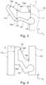
- Fig. 3 shows an exemplary leg 8a of Fig. 1 .
- each of the respective legs is formed in part of the soft component SC, which the soft part 8as of the leg 8a is made of, and in part of the hard component HC, which the hard part 8ah of the leg 8a is made of.
- the hard part 8ah of the legs 8a is formed integrally with a respective sidewall 5, and a film hinge 10a is formed between the leg 8a and the wall 5 with a thickness of the hard component HC measured, in the present example, in the insertion direction I, at the position of the film hinge h being smaller than the thickness of the hard part 8ah of the respective leg in another part.
- the film hinge 10a provides for the flexibility of the arm 8a when the edge 7 is inserted into the gap 6 and allows the bending of the leg 8a without bending a flat surface part 11a, here formed with the soft part 8as, and which is configured to lie against a flat edge 7 introduced into the gap 6, thus maintaining the flat shape of the flat surface part 11a, obtaining maximal friction force.
- the soft part 8as comprises an anchor 12a which is located in the part of the sidewall 5 formed of the hard component HC.
- the legs 8a have a maximal thickness hm in a middle area 13a located between a first end area 13at at a tip of the leg 8a and a second end area 13ab at a base of the leg 8a.
- the middle area corresponds to the heel of a foot
- the first end area 13at corresponds to the toes of a human foot
- the second end area 13ab with the hinge 10a corresponds to the knee of the leg.
- Fig. 4 shows a detail corresponding to the detail of Fig. 3 for the example shown in Fig. 2 .
- the flat surface part 11a which is configured to lie against the flat edge 7 introduced into the gap 6 maximizes the friction force due to the characteristics of the soft component SC. Note that the leg 8a is deformed only in the area of the hinge 10a.
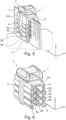
- Fig. 5 shows another yet similar embodiment of an edge clip 1, which features not three, but four legs 8a, 8b, 8c, 8d on each sidewall 5, 5'.
- the flat surfaces 11a of the respective legs 8a to 8d preferably are arranged parallel to each other, be it in contact with the edge 7, as also shown in Fig. 2 , or not in contact with edge 7, as shown in Fig. 1 .
- Fig. 6 shows another exemplary embodiment of an edge clip 1, where three legs 8a - 8c, 8a' - 8c' are disposed at the respective sidewalls 5, 5'.
- the legs 8a - 8c' are entirely made of the soft component, and, in the present example, also connected to each other via an insert 14 extending through a channel that allows the injection molding of all legs 8a - 8c, 8a' - 8c' in one single step.
Abstract
Description
- The present disclosure relates to an edge clip for attaching an item to an edge, in particular for attaching a cable tie to an edge, comprising a first part with a holding fixture for the item, such as an eye for the cable tie, and a second part with two sidewalls, forming a gap between the two sidewalls, wherein when the edge clip is plugged/mounted onto the edge, the edge is introduced into the gap in an insertion direction, where the first part and sidewalls are formed integrally with each other and where the top part and at least a part of the sidewalls are formed of a hard component.
- In order to attach one or more items to an edge, several types of edge clips are known from the state-of-the-art. An exemplary solution is shown in
US 9 328 756 B2 JP 6 546 699 B2 EP 3 091 977 B1US 7 819 365 B2 andUS 7 725 991 B2 . -
EP 3 263 916 B1 - It can there be considered an objective of the present disclosure to improve the known solutions for attaching items to an edge.
- This objective is solved by the subject-matter of the independent claims. Advantageous embodiments are apparent from the dependent claims, the description, and the figures.
- One aspect relates to an edge clip for attaching an item to an edge of an object, in particular for attaching a cable tie to an edge, comprising a first part, which may also be referred to as top part, with a holding fixture for the item, for instance an eye for the cable tie, and a second part, which may be referred to as bottom part, with two sidewalls, forming a gap between the two sidewalls. There, when the edge clip is plugged onto the edge, the edge is introduced into the gap in an insertion direction. The first part and the sidewalls are formed integrally with each other, and the first part and at least a part of the sidewalls are formed of a hard component. The first part can thus be considered as a bridge between the two sidewalls of the second part, resulting in an edge clip with a U-shaped body with the hard component which comprises the second part with the two sidewalls and the first part with the holding fixture. This basic design corresponds to the design of known edge clips.
- Integrally with each of the sidewalls, at least two respective legs, which may also be referred to as tongues, claws, tabs, or fingers, are formed. These (in total at least four) legs protrude into the gap (from the sidewalls) in order to hold the edge inside the gap once it is introduced into the gap. Thus, the legs are flexible with respect to the sidewalls and can be bent towards the sidewalls when introducing the edge into the gap. Correspondingly, the main extension of the respective legs in a plane perpendicular to the edge, (short for: the main extension plane of the edge to be introduced into the gap), and parallel to the insertion direction can be oriented in an angle of about 45° to the main extension plane of the edge once the edge is held in the gap by the legs, and an angle greater than 45°, for instance of about 90°, when no edge is in the gap.
- The legs are formed at least in part of a soft component, meaning that they are formed in part of a soft component or completely of a soft component. The soft component is soft as compared to the hard component. Soft and hard component may be a soft plastic component and/or hard plastic component, respectively. An exemplary hard plastic component may be polyamide with glass fiber, such as PA66-GF15 (15% glass fiber), PA66-GF30 (30% glass fiber), PA6-GF15, or PA6-GF30, or polyamide without glass fiber, such as PA6 or PA66; an exemplary soft plastic component may be a thermoplastic elastomer or thermoplastic polyester-polyurethane. The best results are achieved when the legs of the different sidewalls are offset with respect to each other in the insertion direction. In particular, the legs of the different sidewalls may be arranged in the insertion direction in an alternating order, that is, in the insertion direction a leg of one sidewall is followed by a leg of the other sidewall, which in its turn is followed by another leg on the first sidewall, and so on. By this a push-force required for pushing the edge into the gap is reduced.
- The present disclosure is based on the insight that a combination of soft and hard materials, which is inspired by the shape and surface configuration of human legs makes it possible to provide, via the soft component, enough friction force between the edge and the edge clips since the legs provide, via the hard or soft component, enough spring force to press the parts of the legs that are formed of the soft component against the edge. The respective offset of the legs in the insertion direction reduces the required push force, as the legs are spread serially, one after another, whereas a high pull force is maintained as, once the edge is inserted into the gap and in contact with two or more legs, the different contributions of the different legs to the pull force add up, leading, in the end, to an increased difference of the push and pull force, even for a hard sheet metal where conventional metal claws are of limited use. So, instead of a sharp point or edge of a metal tongue as known in existing edge clips that basically cut into the surface of the edge onto which the edge clip is attached, in the end relying on deforming the edge und thus holding the conventional edge clip in place, the edge clip at hand is held in place on the edge by a friction force that is maintained by the use of a spring force.
- This results in the advantage that the edge clip can be produced as one integrated part without the need for a metal clip, which results in an reduced assembly time for the edge clip and a high difference of the push force and the pull force, which is required for pulling the edge clip from the edge after it has been attached to the edge, in particular for an edge made from hard sheet metal. Furthermore, corrosion commonly induced by the contact of the metal clip with the metal edge in conventional designs, and ultimately leading to unsecure attachment in the long term, is avoided. Thus, a more reliable attachment of the edge clip to the edge is achieved.
- In an advantageous embodiment, each of the respective legs protrudes, when the edge is not introduced into the gap, into the gap further than a centre plane of the gap, where the centre plane is equally distanced from both of the sidewalls. This gives the advantage that the size of the respective legs, and thus also the contact area of the legs, i.e. the friction which is used to hold the edge within the gap, can be made bigger, thus resulting in a more reliable attachment of the edge clip to the edge.
- In another advantageous embodiment, the edge clip is injection-mold. So, it may form one single part which can only be decomposed by destruction. This gives the advantage of a reduced production effort and an increased stability of the edge clip, resulting in an increased reliability of the attachment of the edge clip to the edge.
- In yet another advantageous embodiment, each of the respective legs has a flat surface part, the contact area, which is configured to lie against a flat edge such as a metal sheet, introduced into the gap, where the flat surface part in part or completely consists of soft component. Therein, the flat surface part preferably is an end surface of the leg. Such an end surface is a surface that either includes an end of the respective leg in the direction of the flat surface part and/or a surface that is close enough to said end so that a remaining part between the end and the end surface corresponds only to a fraction, for instance less than 205 or less than 10% or less than 5%, of the length of the flat surface part in said direction. This gives the advantage that the friction force of the respective legs is increased, and consequently the reliability of the attachment of the edge clip to the edge is improved. To this end, the respective flat surfaces may feature a surface texture for increasing friction forces. Such a texture may be referred to micro-texture, as it is very small in relation to the size of the respective legs, e.g. smaller by an order of magnitude.
- In another advantageous embodiment, each of the respective legs is formed in part of the soft component, which forms a soft part of the respective leg, and in part of the hard component, which forms a hard part of the respective leg. This gives the advantage that the friction force provided by the soft component is increased as an available spring force used to press the soft part of the leg against the edge in the gap can be increased by the hard component, as the hard component is harder than the soft component.
- Therein, the hard part of the legs may be formed integrally with the respective sidewall, and a film hinge may be formed between the respective leg and the wall, with a thickness of the hard component at the position of the film hinge being smaller than the thickness of the hard part of the respective leg in another part, in particular any other part of the hard part of the leg. In other words, the film hinge may be the weakest spot or part of the hard part of the legs. The thickness of the hard component may be measured in a given direction in a plane which is perpendicular to the edge and parallel to the insertion direction, in particular the thickness may be measured in the insertion direction. This gives the advantage that the legs are only deformed in a very specific and well defined area, that is, the film hinge, when the edge is introduced into the gap. As a consequence, the soft part of the leg which provides the friction force necessary to hold the edge in the gap can be designed precisely to maximize friction forces and will not be deformed in an undefined way. Consequently, the reliability of the attachment of the edge clip to the edge is further increased.
- The soft part of the legs may be closer to an opening of the gap, from which the edge is inserted into the gap in the insertion direction, than the hard part of the respective leg. So when the edge is inserted into the gap, it will encounter the soft part prior to the hard part, provided it encounters the hard part at all. This is making sure the edge is actually in contact with the soft part of the legs once it is inserted into the gap.
- Preferably, the soft part comprises an anchor which is located in the part of the sidewall formed of the hard component. The anchor may be a part of the soft part which is thicker than the rest of the soft part, and which may be backinjection-molded into the part of the sidewall formed of the hard component.
- The anchor may be held in place by a narrowing in the hard component, behind which a thicker part, a head of the anchor is positioned. This gives the advantage that the soft part cannot be teared off the hard part of the legs, thus further improving the reliability of the attachment of the edge clip to the edge.
- In another advantageous embodiment, exactly three respective legs protruding into the gap are formed integrally with each of the sidewalls. While the edge clip also works reliably with two or four respective legs per sidewall, it turned out that the use of three respective legs per sidewall result in the optimal behaviour. Here, the respective legs are counted in a plane parallel to the insertion direction and perpendicular to the edge to be inserted into the gap, thus exactly three respective legs per sidewall comprise also more respective legs per sidewall, which may be arranged as a series of legs along the edge perpendicular to the insertion direction.
- In another advantageous embodiment, the respective legs of each of the respective sidewalls are at least in part arranged behind each other in the insertion direction, meaning they are arranged behind each other in the insertion direction in part or completely behind each other. This ensures that the edge is held in place particularly secure, again contributing to the reliability of the attachment of the edge clip to the edge.
- In an advantageous embodiment, the legs have, in a plane parallel to the insertion direction and perpendicular to the edge, an identical profile or cross section. This gives the advantage of a particular homogeneous distribution of friction and spring forces which again increases the reliability of the attachment of the edge clip to the edge.
- In another advantageous embodiment, each of the legs has a maximal thickness in a middle area located between a first end area at the tip of the leg, which is distanced from the respective sidewall, and a second end area at a base of the leg, which is adjacent to the respective sidewall. The thickness preferably is measured in the insertion direction or another direction in a plane which perpendicular to the edge and parallel to the insertion direction, when the edge is not introduced into the gap. In particular, the first end area may be part of the flat surface part of the respective legs, where said middle area with a maximal thickness enhances the stability of the flat surface part and thus the reliability of the friction force. The middle area corresponds to the heel of the human leg, which similar to the legs of the edge clip of the present disclosure use a hard component, bones, to press a soft component, the sole of the foot (which corresponds to the flat surface part), onto the area where maximal friction is to be achieved, the ground.
- Another aspect relates to a method for injection-molding an edge clip for attaching an item to an edge, the edge clip comprising first part with a holding fixture for the item and a second part with two sidewalls, forming a gap between the two sidewalls, where when the edge clip is plugged onto the edge, the edge is introduced into the gap in an insertion direction. The method comprises the method steps of a hard-component injection-molding of the first part and at least a part of the sidewalls using a hard injection molding component, and a soft-component injection-molding of at least parts of at least two respective legs on each of the sidewall, the legs protruding into the gap. There, the soft component is soft as compared to the hard component.
- Advantages and advantageous embodiments of the method correspond to advantages and advantageous embodiments of the edge clip described above.
- The features and combinations of features described above, including the general part of the description, as well as the features and combinations of features disclosed in the figure description or the figures alone may not only be used alone or in the described combination, but also with other features or without some of the disclosed features without departing from the scope of the present disclosure. Consequently, embodiments that are not explicitly shown and described by the figures but that can be generated by separately combining the individual features disclosed in the figures are also part of the present disclosure. Therefore, embodiments and combinations of features that do not comprise all features of an originally formulated independent claim are to be regarded as disclosed. Furthermore, embodiments and combinations of features that differ from or extend beyond the combinations of features described by the dependencies of the claims are to be regarded as disclosed.
- Exemplary embodiments are further described in the following by means of schematic drawings. Therein,
-
Fig. 1 shows a cross section of an exemplary embodiment of an edge clip before an item is introduced into the gap of the edge clip; -
Fig. 2 shows the edge clip ofFig. 1 with the item introduced into the gap; -
Fig. 3 shows a cross section through an exemplary leg ofFig. 1 ; -
Fig. 4 shows a cross section through an exemplary leg ofFig. 2 ; -
Fig. 5 is a perspective view of another exemplary embodiment of an edge clip with an item introduced into the gap; and -
Fig. 6 is a perspective view of yet another exemplary embodiment of an edge clip. - In the different figures the identical or functionally identical elements have the same reference signs.
-
Fig. 1 shows an exemplary embodiment of anedge clip 1 for attaching an item, in the present example a cable tie, to anedge 7 of an object. Theedge clip 1 comprises afirst part 2 with a holdingfixture 3, here an eye for a cable tie, and asecond part 4 with twosidewalls 5 and 5', forming agap 6 between the twosidewalls 5 and 5', where when theedge clip 1 is mounted onto theedge 7, theedge 7 is introduced into thegap 6 in an insertion direction I. - Therein, the
first part 2 and thesidewalls 5, 5' are formed integrally with each other, and thefirst part 2 and at least part of thesidewalls 5, 5' are formed of a hard component HC. - In addition, at least two, in the present example three
respective legs gap 6 are formed integrally with therespective sidewalls 5 and 5'. Here, thelegs first sidewall 5 are offset with respect to thelegs 8a', 8b', 8c' of the second sidewall 5', and are arranged in an alternating order. Thelegs 8a - 8c' are formed at least in part of a soft component SC which is soft as compared to the hard component HC. In the present example, each of therespective legs 8a to 8c' protrudes into thegap 6 further than a centre plane CP of thegap 6, which is equally distanced from both of thesidewalls 5, 5'. In addition, a soft part 8as (Fig. 3 ) of the legs, which is the part of therespective leg 8a-8c' made of the soft component SC, in the present example, is closer to anopening 9 of the gap, from which theedge 7 is inserted into thegap 6 in the insertion direction I, than a hard part 8ah (Fig. 3 ) of the respective legs, which is the part of therespective leg 8a-8c' made of the hard component HC. The use of the hard component HC for thelegs 8a-8c' increases a spring force which pushes thelegs 8a-8c' back into the neutral position shown inFig. 1 when moved by an item as shown inFig. 2 . In the present example, thelegs 8a - 8c' have, in an x-y-plane parallel to the insertion direction and perpendicular to the edge, an identical profile. - When the
edge 7 is introduced into thegap 6 in the insertion direction I along the centre plane CP, each of thelegs 8a - 8c' is bent away from the centre plane CP individually, thereby reducing the push force for inserting theedge 7 into thegap 6. - In
Fig. 2 , the exemplary embodiment ofFig. 1 is shown with theedge 7 introduced into thegap 6. Due to the spring force associated with the hard component HC thesidewalls 5, 5' and parts of thelegs 8a to 8c are made from in the present example, the soft component SC which forms part of thelegs 8a - 8c' is pressed against theedge 7, resulting in an increased friction between the soft component SC and theedge 7. Correspondingly, with increasing number oflegs 8a - 8c, the pull force increasingly adds up, resulting in a high difference of push and pull force for the displayededge clip 1. -
Fig. 3 shows anexemplary leg 8a ofFig. 1 . Here, each of the respective legs is formed in part of the soft component SC, which the soft part 8as of theleg 8a is made of, and in part of the hard component HC, which the hard part 8ah of theleg 8a is made of. In the shown example, the hard part 8ah of thelegs 8a is formed integrally with arespective sidewall 5, and afilm hinge 10a is formed between theleg 8a and thewall 5 with a thickness of the hard component HC measured, in the present example, in the insertion direction I, at the position of the film hinge h being smaller than the thickness of the hard part 8ah of the respective leg in another part. Thefilm hinge 10a provides for the flexibility of thearm 8a when theedge 7 is inserted into thegap 6 and allows the bending of theleg 8a without bending aflat surface part 11a, here formed with the soft part 8as, and which is configured to lie against aflat edge 7 introduced into thegap 6, thus maintaining the flat shape of theflat surface part 11a, obtaining maximal friction force. Furthermore, in the present example, the soft part 8as comprises ananchor 12a which is located in the part of thesidewall 5 formed of the hard component HC. In order to optimize the reliability of the attachment of the edge clip to the edge, thelegs 8a have a maximal thickness hm in amiddle area 13a located between a first end area 13at at a tip of theleg 8a and a second end area 13ab at a base of theleg 8a. In analogy of the human leg or foot, the middle area corresponds to the heel of a foot, where the first end area 13at corresponds to the toes of a human foot, and the second end area 13ab with thehinge 10a corresponds to the knee of the leg. -
Fig. 4 shows a detail corresponding to the detail ofFig. 3 for the example shown inFig. 2 . Theflat surface part 11a, which is configured to lie against theflat edge 7 introduced into thegap 6 maximizes the friction force due to the characteristics of the soft component SC. Note that theleg 8a is deformed only in the area of thehinge 10a. -
Fig. 5 shows another yet similar embodiment of anedge clip 1, which features not three, but fourlegs sidewall 5, 5'. Again, it becomes apparent that theflat surfaces 11a of therespective legs 8a to 8d preferably are arranged parallel to each other, be it in contact with theedge 7, as also shown inFig. 2 , or not in contact withedge 7, as shown inFig. 1 . -
Fig. 6 shows another exemplary embodiment of anedge clip 1, where threelegs 8a - 8c, 8a' - 8c' are disposed at therespective sidewalls 5, 5'. In the shown example, thelegs 8a - 8c' are entirely made of the soft component, and, in the present example, also connected to each other via aninsert 14 extending through a channel that allows the injection molding of alllegs 8a - 8c, 8a' - 8c' in one single step.
Claims (13)
- Edge clip (1) for attaching an item to an edge (7) of an object, comprising- a first part (2) with a holding fixture (3) for the item; and- a second part (4) with two sidewalls (5, 5'), forming a gap (6) between the two sidewalls (5, 5'), wherein when the edge clip (1) is mounted onto the edge (7), the edge (7) is introduced into the gap (6) in an insertion direction (I);- wherein the first part (2) and the sidewalls (5, 5') are formed integrally with each other, and- wherein the first part (2) and at least a part of the sidewalls (5, 5') are formed of a hard component (HC);characterized in that- at least two respective legs (8a-8d, 8a'- 8c') protruding into the gap (6) are formed integrally with each of the sidewalls (5, 5');- where the legs (8a-8d, 8a'- 8c') of the different sidewalls (5, 5') are offset with respect to each other in the insertion direction (I); and- where the legs (8a-8d, 8a'- 8c') are formed at least in part of a soft component (SC), which is soft as compared to the hard component (HC).
- Edge clip (1) according to claim 1,
characterized in that
each of the respective legs (8a-8d, 8a'- 8c') protrudes, when the edge (7) is not introduced into the gap (6), into the gap (6) further than a centre plane (CP) of the gap (6), which is equally distanced from both of the sidewalls (5, 5'). - Edge clip (1) according to any one of the preceding claims, characterized in that
the edge clip (1) is injectionmolded. - Edge clip (1) according to any one of the preceding claims,
characterized in that
each of the respective legs (8a-8d, 8a'- 8c') has a flat surface part (11a), which is configured to lie against a flat edge (7) introduced into the gap (6), where the flat surface part (11a) in part or completely consists of the soft component (SC). - Edge clip (1) according to any one of the preceding claims,
characterized in that
each of the respective legs (8a-8d, 8a'- 8c') is formed in part of the soft component (SC), which forms a soft part (8as) of the leg (8a), and in part of the hard component (HC), which forms a hard part (8ah) of the leg (8a). - Edge clip (1) according to claim 5,
characterized in that
the hard part (8ah) of the legs (8a-8d, 8a'- 8c') is formed integrally with the respective sidewall (5, 5'), and a film hinge (10a) is formed between the leg (8a-8d, 8a'- 8c') and the respective sidewall (5, 5'), with a thickness (h) of the hard component (HC) measured in the insertion direction (I), at the position of the film hinge (10a) being smaller than the thickness of the hard part (8ah) of the respective leg (8a) in any other part of the hard part (8ah) of the leg (8a). - Edge clip (1) according to claim 5 or 6,
characterized in that
the soft part (8as) of the legs (8a-8d, 8a'- 8c') is closer to an opening (9) of the gap (6), from which the edge (7) is inserted into the gap (6) in the insertion direction (I), than the hard part (8ah) of the respective leg (8a-8d, 8a'-8c'). - Edge clip (1) according to any one of claims 5 to 7,
characterized in that
the soft part (8as) comprises an anchor (12a) which is located in the part of the sidewall (5, 5') formed of the hard component (HC). - Edge clip (1) according to any one of the preceding claims,
characterized in that
exactly three respective legs (8a-8d, 8a'- 8c') protruding into the gap (6) are formed integrally with each of the sidewalls (5, 5'). - Edge clip (1) according to any one of the preceding claims,
characterized in that
the respective legs (8a-8d, 8a'- 8c') of each of the respective sidewalls (5, 5') are at least in part arranged behind each other in the insertion direction (I). - Edge clip (1) according to any one of the preceding claims,
characterized in that
the legs (8a-8d, 8a'- 8c') have, in a plane parallel to the insertion direction (I) and perpendicular to the edge (7), an identical profile. - Edge clip (1) according to any one of the preceding claims,
characterized in that
each of the legs (8a-8d, 8a'- 8c') has a maximal thickness (hm), preferably measured in the insertion direction (I), in a middle area (13a) located between a first end area (13at) at a tip (8a) of the leg and a second end area (13ab) at a base of the leg (8a). - Method for insertion-molding an edge clip (1) for attaching an item to an edge (7), the edge clip (1) comprising a first part (2) with a holding fixture for the item and a second part (4) with two sidewalls (5, 5'), forming a gap (6) between the two sidewalls (5, 5'), where when the edge clip (1) is mounted onto the edge (7), the edge (7) is introduced into the gap (6) in an insertion direction (I), with the methods steps of:- a hard-component injection-molding of the first part (2) and at least a part of the sidewalls (5, 5') using a hard injection-molding component (HC);- a soft-component injection-molding of at least parts of at least two respective legs (8a-8d, 8a'- 8c') onto each of the sidewalls (5, 5') using a soft injection-molding component (SC), the legs (8a-8d, 8a'- 8c') protruding into the gap (6);where the soft component (SC) is soft as compared to the hard component (HC).
Priority Applications (4)
| Application Number | Priority Date | Filing Date | Title |
|---|---|---|---|
| EP21190204.4A EP4131687A1 (en) | 2021-08-06 | 2021-08-06 | Edge clip |
| CN202210937730.9A CN115912218A (en) | 2021-08-06 | 2022-08-05 | Edge clamp |
| US17/817,797 US11873851B2 (en) | 2021-08-06 | 2022-08-05 | Edge clip |
| US18/526,551 US20240102498A1 (en) | 2021-08-06 | 2023-12-01 | Edge Clip |
Applications Claiming Priority (1)
| Application Number | Priority Date | Filing Date | Title |
|---|---|---|---|
| EP21190204.4A EP4131687A1 (en) | 2021-08-06 | 2021-08-06 | Edge clip |
Publications (1)
| Publication Number | Publication Date |
|---|---|
| EP4131687A1 true EP4131687A1 (en) | 2023-02-08 |
Family
ID=77367252
Family Applications (1)
| Application Number | Title | Priority Date | Filing Date |
|---|---|---|---|
| EP21190204.4A Pending EP4131687A1 (en) | 2021-08-06 | 2021-08-06 | Edge clip |
Country Status (3)
| Country | Link |
|---|---|
| US (2) | US11873851B2 (en) |
| EP (1) | EP4131687A1 (en) |
| CN (1) | CN115912218A (en) |
Families Citing this family (1)
| Publication number | Priority date | Publication date | Assignee | Title |
|---|---|---|---|---|
| CN113483157A (en) | 2021-08-06 | 2021-10-08 | 海尔曼太通(无锡)电器配件有限公司 | Quick assembly disassembly pipe clamp |
Citations (9)
| Publication number | Priority date | Publication date | Assignee | Title |
|---|---|---|---|---|
| US4105814A (en) * | 1976-03-27 | 1978-08-08 | Schlegel Gmbh | Profile strip of U-shaped cross-section, in particular an edge protection strip for automobile |
| US7725991B2 (en) | 2002-05-28 | 2010-06-01 | Newfrey Llc | Low insertion effort fastener with offset for wing |
| US7819365B2 (en) | 2007-01-22 | 2010-10-26 | Trw Automotive Electronics & Components Gmbh | Fastening device for cables |
| US8578571B2 (en) * | 2008-08-07 | 2013-11-12 | Newfrey Llc | Plastic clip |
| US9328756B2 (en) | 2013-12-09 | 2016-05-03 | Trw Automotive Electronics & Components Gmbh | Fixing device for cables |
| EP3091977A2 (en) | 2013-12-30 | 2016-11-16 | Oncoprevent GmbH | Neurokinin-1 receptor antagonists for use in a method of prevention of cancer |
| FR3074547A1 (en) * | 2017-12-04 | 2019-06-07 | Illinois Tool Works Inc | FASTENING CLAMP ON A SHEET EDGE FOR A MOTOR VEHICLE |
| JP6546699B2 (en) | 2016-05-18 | 2019-07-17 | 株式会社パイオラックス | clip |
| EP3263916B1 (en) | 2016-06-29 | 2020-04-01 | Nexans | Device for attaching an object |
Family Cites Families (58)
| Publication number | Priority date | Publication date | Assignee | Title |
|---|---|---|---|---|
| SE7703556L (en) | 1977-03-28 | 1978-09-29 | Ohlson Kurt L | DEVICE FOR HOLDING TWO PARALLEL OR ATMINSTONE ESSENTIAL PARALLEL-ORIENTED BODIES |
| US4184297A (en) * | 1978-06-05 | 1980-01-22 | Plaskolite, Inc. | Extruded plastic panel holding and jointing strips and window assemblies therewith |
| US4395009A (en) | 1981-05-28 | 1983-07-26 | The Boeing Company | Raceway clamp |
| GB2163470A (en) * | 1984-08-23 | 1986-02-26 | Silent Channel Prod Ltd | Sealing strip |
| US5098054A (en) | 1990-07-09 | 1992-03-24 | Tyton Corporation | Mounting bracket for a generally cylindrical article |
| US5148576A (en) | 1991-10-07 | 1992-09-22 | Tyton Corporation | Conduit clamp |
| US5157815A (en) | 1991-10-07 | 1992-10-27 | Tyton Corporation | Conduit clamp |
| US5216784A (en) | 1991-10-07 | 1993-06-08 | Tyton Corporation | Conduit clamp |
| US5505411A (en) | 1992-10-29 | 1996-04-09 | Tyton Corporation | Harness fixing device |
| US5301917A (en) | 1992-11-23 | 1994-04-12 | Tyton Corporation | Brake line isolator |
| US5772258A (en) | 1995-12-20 | 1998-06-30 | Tyton-Hellermann Corp. | Conduit clamp and tether |
| US5820083A (en) | 1997-02-28 | 1998-10-13 | Tyton-Hellermann Corporation | Heavy duty cable tie mount |
| US5937488A (en) | 1998-07-13 | 1999-08-17 | Tyton Hellerman Corporation | Brakeline to axle clamp |
| US6112499A (en) | 1999-01-19 | 2000-09-05 | Hellermanntyton Corporation | Bag closure apparatus |
| US20020071715A1 (en) | 2000-02-23 | 2002-06-13 | Hellermanntyton Corporation | Dual swivel saddle spacer |
| DE10035020A1 (en) | 2000-07-18 | 2002-01-31 | Wolf Woco & Co Franz J | Bracket for holding pipes, especially for hydraulic systems |
| US6533226B2 (en) | 2000-09-14 | 2003-03-18 | Hellermanntyton Corporation | Saddle mount |
| EP1231158A1 (en) | 2001-02-12 | 2002-08-14 | Hellermann Tyton GmbH | Strip of interconnected locking pieces for tightening straps and tool for their application |
| US20030222184A1 (en) | 2002-05-30 | 2003-12-04 | Hellermann Tyton Corporation | Axial oval mount for elongate article having a flexible tie |
| US7377472B2 (en) | 2002-12-16 | 2008-05-27 | Securus, Inc. | Pipe and cable holder |
| US6736669B1 (en) | 2003-01-14 | 2004-05-18 | Martin Dennis J | Cable organizing and securing device |
| EP1473499A1 (en) | 2003-05-02 | 2004-11-03 | Hellermann Tyton GmbH | Holding device for elongated articles |
| US20130119208A1 (en) | 2004-04-30 | 2013-05-16 | Hellermanntyton Corporation | Fir tree mount for cable ties |
| US20120217355A1 (en) | 2004-04-30 | 2012-08-30 | Hellermann Tyton Corporation | Oval fir tree mount |
| US20160223100A1 (en) | 2004-04-30 | 2016-08-04 | Hellermann Tyton Corporation | Fir tree mount |
| US8028962B2 (en) | 2004-04-30 | 2011-10-04 | Hellermanntyton Corporation | Fir tree mount for cable ties |
| USD543835S1 (en) | 2005-05-19 | 2007-06-05 | Hellermanntyton Corporation | Dual swivel saddle spacer |
| US7753320B2 (en) | 2005-07-28 | 2010-07-13 | Hellermanntyton Corporation | Flush mount connector clip |
| US7938365B2 (en) | 2005-08-22 | 2011-05-10 | Airbus Deutschland Gmbh | Line holder in an aircraft |
| DE202005017160U1 (en) | 2005-11-03 | 2007-04-05 | Hellermann Tyton Gmbh | Mounting rail for an elongated object |
| US20070272807A1 (en) | 2006-05-18 | 2007-11-29 | Hellermanntyton Co., Ltd. | Part mounting clamp |
| DE202007008610U1 (en) | 2007-06-20 | 2007-10-04 | Hellermann Tyton Gmbh | fastening system |
| US20100199463A1 (en) | 2007-09-21 | 2010-08-12 | Newfrey Llc | Band clamp for elongated member |
| US8141826B1 (en) | 2008-01-15 | 2012-03-27 | Securus, Inc. | Pipe holding bracket |
| JP5066731B2 (en) | 2008-03-18 | 2012-11-07 | ポップリベット・ファスナー株式会社 | Multiple wire harness clamps |
| GB201009963D0 (en) | 2010-06-15 | 2010-07-21 | Airbus Operations Ltd | Modular conduit retntion system |
| JP5791953B2 (en) | 2011-04-28 | 2015-10-07 | 株式会社ニフコ | Clamp |
| USD734654S1 (en) | 2013-10-17 | 2015-07-21 | Hellermanntyton Corporation | Mount |
| DE102014016726B3 (en) | 2014-11-13 | 2016-05-19 | Hellermann Tyton Ab | fastening device |
| DE102015102825B3 (en) | 2015-02-27 | 2016-04-28 | Lisa Dräxlmaier GmbH | clamp |
| GB2537901A (en) | 2015-04-30 | 2016-11-02 | Hellermann Tyton Ltd | A Cable Support |
| USD793215S1 (en) | 2015-08-25 | 2017-08-01 | Hellermanntyton Corporation | Blind hole mount |
| JP6602956B2 (en) | 2015-08-25 | 2019-11-06 | ヘラマンタイトン コーポレイション | Blind hole mount |
| GB201516237D0 (en) | 2015-09-14 | 2015-10-28 | Ellis Patents Holdings Ltd | A clamp |
| US10903632B2 (en) | 2016-02-05 | 2021-01-26 | Hellermanntyton Corporation | Adjustable P-clamp with multiple mounting options |
| US10119631B2 (en) | 2016-02-05 | 2018-11-06 | Hellermanntyton Corporation | Adjustable p-clamp |
| USD829090S1 (en) | 2016-04-06 | 2018-09-25 | Hellermanntyton Corporation | Adjustable P clamp |
| USD784799S1 (en) | 2016-04-06 | 2017-04-25 | Hellermann Tyton Corporation | Adjustable P-clamp |
| US10316991B2 (en) | 2016-08-10 | 2019-06-11 | Hellermanntyton Corporation | Wide range edge mounting clamp |
| USD815939S1 (en) | 2016-08-25 | 2018-04-24 | Hellermanntyton Corporation | Blind hole mount |
| US10323774B2 (en) | 2016-09-01 | 2019-06-18 | Hellermanntyton Corporation | Mounting device with self-centering support surface |
| US10208874B2 (en) | 2016-09-29 | 2019-02-19 | Hellermanntyton Corporation | Retaining clip |
| USD822476S1 (en) | 2016-10-26 | 2018-07-10 | Hellermanntyton Corporation | Multiple option clip |
| EP3336989B1 (en) | 2016-12-16 | 2020-07-22 | HellermannTyton GmbH | Cable fixation device |
| USD909844S1 (en) | 2018-10-22 | 2021-02-09 | Hellermanntyton Corporation | Modular adjustable clamp |
| USD909843S1 (en) | 2018-10-22 | 2021-02-09 | Hellermanntyton Corporation | Modular adjustable clamp |
| US11420571B1 (en) * | 2021-02-25 | 2022-08-23 | A. Raymond Et Cie | Serviceable edge clip assembly |
| CN113483157A (en) | 2021-08-06 | 2021-10-08 | 海尔曼太通(无锡)电器配件有限公司 | Quick assembly disassembly pipe clamp |
-
2021
- 2021-08-06 EP EP21190204.4A patent/EP4131687A1/en active Pending
-
2022
- 2022-08-05 CN CN202210937730.9A patent/CN115912218A/en active Pending
- 2022-08-05 US US17/817,797 patent/US11873851B2/en active Active
-
2023
- 2023-12-01 US US18/526,551 patent/US20240102498A1/en active Pending
Patent Citations (9)
| Publication number | Priority date | Publication date | Assignee | Title |
|---|---|---|---|---|
| US4105814A (en) * | 1976-03-27 | 1978-08-08 | Schlegel Gmbh | Profile strip of U-shaped cross-section, in particular an edge protection strip for automobile |
| US7725991B2 (en) | 2002-05-28 | 2010-06-01 | Newfrey Llc | Low insertion effort fastener with offset for wing |
| US7819365B2 (en) | 2007-01-22 | 2010-10-26 | Trw Automotive Electronics & Components Gmbh | Fastening device for cables |
| US8578571B2 (en) * | 2008-08-07 | 2013-11-12 | Newfrey Llc | Plastic clip |
| US9328756B2 (en) | 2013-12-09 | 2016-05-03 | Trw Automotive Electronics & Components Gmbh | Fixing device for cables |
| EP3091977A2 (en) | 2013-12-30 | 2016-11-16 | Oncoprevent GmbH | Neurokinin-1 receptor antagonists for use in a method of prevention of cancer |
| JP6546699B2 (en) | 2016-05-18 | 2019-07-17 | 株式会社パイオラックス | clip |
| EP3263916B1 (en) | 2016-06-29 | 2020-04-01 | Nexans | Device for attaching an object |
| FR3074547A1 (en) * | 2017-12-04 | 2019-06-07 | Illinois Tool Works Inc | FASTENING CLAMP ON A SHEET EDGE FOR A MOTOR VEHICLE |
Non-Patent Citations (1)
| Title |
|---|
| ANONYMOUS: "Edge Mount Cable Tie EDGE MOUNT CABLE TIE MOUNT", 8 August 2018 (2018-08-08), XP055881546, Retrieved from the Internet <URL:https://media.digikey.com/pdf/Data%20Sheets/Richco%20Inc%20PDFs/EdgeMountCableTie_CutSheet.pdf> [retrieved on 20220120] * |
Also Published As
| Publication number | Publication date |
|---|---|
| US20230042349A1 (en) | 2023-02-09 |
| US20240102498A1 (en) | 2024-03-28 |
| CN115912218A (en) | 2023-04-04 |
| US11873851B2 (en) | 2024-01-16 |
Similar Documents
| Publication | Publication Date | Title |
|---|---|---|
| US20240102498A1 (en) | Edge Clip | |
| US10448743B2 (en) | Crip and cord | |
| US7188393B2 (en) | Fastener device | |
| KR102233415B1 (en) | Fastening method and apparatus | |
| US6224030B1 (en) | Hook/hanger | |
| JP2012135180A (en) | Spring clip | |
| US20050230570A1 (en) | Fixing tool | |
| CN117052761A (en) | Fastening clip | |
| US4369946A (en) | Cable clips | |
| KR20090107910A (en) | Paper holder | |
| US11717103B2 (en) | Hanger | |
| EP2405148B1 (en) | Clip for fastening to a strip or rib | |
| GB2058192A (en) | Cable Clips | |
| US6086030A (en) | Hook/hanger | |
| JPH11153112A (en) | Anchor leg clip | |
| EP4068539A1 (en) | Cable clip | |
| JP2006187095A (en) | Long object fixture | |
| KR102191891B1 (en) | Clip and connector assembly | |
| CN113260794B (en) | Belt type clamp | |
| KR20020045526A (en) | conneting structure | |
| WO2014016339A1 (en) | Clip for fastening to a flat component | |
| JP3456940B2 (en) | Spelling implement | |
| JP2001298835A (en) | Wire material bundle holding tool | |
| JP2003202428A (en) | Corner guide for optical fiber and optical fiber holder | |
| KR20070016816A (en) | Knob for a switch of an electric appliance |
Legal Events
| Date | Code | Title | Description |
|---|---|---|---|
| PUAI | Public reference made under article 153(3) epc to a published international application that has entered the european phase |
Free format text: ORIGINAL CODE: 0009012 |
|
| STAA | Information on the status of an ep patent application or granted ep patent |
Free format text: STATUS: THE APPLICATION HAS BEEN PUBLISHED |
|
| AK | Designated contracting states |
Kind code of ref document: A1 Designated state(s): AL AT BE BG CH CY CZ DE DK EE ES FI FR GB GR HR HU IE IS IT LI LT LU LV MC MK MT NL NO PL PT RO RS SE SI SK SM TR |
|
| STAA | Information on the status of an ep patent application or granted ep patent |
Free format text: STATUS: REQUEST FOR EXAMINATION WAS MADE |
|
| 17P | Request for examination filed |
Effective date: 20230704 |
|
| RBV | Designated contracting states (corrected) |
Designated state(s): AL AT BE BG CH CY CZ DE DK EE ES FI FR GB GR HR HU IE IS IT LI LT LU LV MC MK MT NL NO PL PT RO RS SE SI SK SM TR |