WO2012147180A1 - 真空脱ガス槽及びこれを用いた脱ガス処理方法 - Google Patents
真空脱ガス槽及びこれを用いた脱ガス処理方法 Download PDFInfo
- Publication number
- WO2012147180A1 WO2012147180A1 PCT/JP2011/060278 JP2011060278W WO2012147180A1 WO 2012147180 A1 WO2012147180 A1 WO 2012147180A1 JP 2011060278 W JP2011060278 W JP 2011060278W WO 2012147180 A1 WO2012147180 A1 WO 2012147180A1
- Authority
- WO
- WIPO (PCT)
- Prior art keywords
- mass
- vacuum degassing
- refractory
- alloy
- graphite
- Prior art date
- Legal status (The legal status is an assumption and is not a legal conclusion. Google has not performed a legal analysis and makes no representation as to the accuracy of the status listed.)
- Ceased
Links
Images




Classifications
-
- C—CHEMISTRY; METALLURGY
- C04—CEMENTS; CONCRETE; ARTIFICIAL STONE; CERAMICS; REFRACTORIES
- C04B—LIME, MAGNESIA; SLAG; CEMENTS; COMPOSITIONS THEREOF, e.g. MORTARS, CONCRETE OR LIKE BUILDING MATERIALS; ARTIFICIAL STONE; CERAMICS; REFRACTORIES; TREATMENT OF NATURAL STONE
- C04B35/00—Shaped ceramic products characterised by their composition; Ceramics compositions; Processing powders of inorganic compounds preparatory to the manufacturing of ceramic products
- C04B35/01—Shaped ceramic products characterised by their composition; Ceramics compositions; Processing powders of inorganic compounds preparatory to the manufacturing of ceramic products based on oxide ceramics
- C04B35/03—Shaped ceramic products characterised by their composition; Ceramics compositions; Processing powders of inorganic compounds preparatory to the manufacturing of ceramic products based on oxide ceramics based on magnesium oxide, calcium oxide or oxide mixtures derived from dolomite
- C04B35/04—Shaped ceramic products characterised by their composition; Ceramics compositions; Processing powders of inorganic compounds preparatory to the manufacturing of ceramic products based on oxide ceramics based on magnesium oxide, calcium oxide or oxide mixtures derived from dolomite based on magnesium oxide
- C04B35/043—Refractories from grain sized mixtures
-
- C—CHEMISTRY; METALLURGY
- C21—METALLURGY OF IRON
- C21C—PROCESSING OF PIG-IRON, e.g. REFINING, MANUFACTURE OF WROUGHT-IRON OR STEEL; TREATMENT IN MOLTEN STATE OF FERROUS ALLOYS
- C21C7/00—Treating molten ferrous alloys, e.g. steel, not covered by groups C21C1/00 - C21C5/00
- C21C7/04—Removing impurities by adding a treating agent
-
- C—CHEMISTRY; METALLURGY
- C21—METALLURGY OF IRON
- C21C—PROCESSING OF PIG-IRON, e.g. REFINING, MANUFACTURE OF WROUGHT-IRON OR STEEL; TREATMENT IN MOLTEN STATE OF FERROUS ALLOYS
- C21C7/00—Treating molten ferrous alloys, e.g. steel, not covered by groups C21C1/00 - C21C5/00
- C21C7/10—Handling in a vacuum
-
- F—MECHANICAL ENGINEERING; LIGHTING; HEATING; WEAPONS; BLASTING
- F27—FURNACES; KILNS; OVENS; RETORTS
- F27D—DETAILS OR ACCESSORIES OF FURNACES, KILNS, OVENS OR RETORTS, IN SO FAR AS THEY ARE OF KINDS OCCURRING IN MORE THAN ONE KIND OF FURNACE
- F27D1/00—Casings; Linings; Walls; Roofs
-
- F—MECHANICAL ENGINEERING; LIGHTING; HEATING; WEAPONS; BLASTING
- F27—FURNACES; KILNS; OVENS; RETORTS
- F27D—DETAILS OR ACCESSORIES OF FURNACES, KILNS, OVENS OR RETORTS, IN SO FAR AS THEY ARE OF KINDS OCCURRING IN MORE THAN ONE KIND OF FURNACE
- F27D1/00—Casings; Linings; Walls; Roofs
- F27D1/0003—Linings or walls
- F27D1/0006—Linings or walls formed from bricks or layers with a particular composition or specific characteristics
-
- C—CHEMISTRY; METALLURGY
- C04—CEMENTS; CONCRETE; ARTIFICIAL STONE; CERAMICS; REFRACTORIES
- C04B—LIME, MAGNESIA; SLAG; CEMENTS; COMPOSITIONS THEREOF, e.g. MORTARS, CONCRETE OR LIKE BUILDING MATERIALS; ARTIFICIAL STONE; CERAMICS; REFRACTORIES; TREATMENT OF NATURAL STONE
- C04B2235/00—Aspects relating to ceramic starting mixtures or sintered ceramic products
- C04B2235/02—Composition of constituents of the starting material or of secondary phases of the final product
- C04B2235/30—Constituents and secondary phases not being of a fibrous nature
- C04B2235/40—Metallic constituents or additives not added as binding phase
- C04B2235/401—Alkaline earth metals
-
- C—CHEMISTRY; METALLURGY
- C04—CEMENTS; CONCRETE; ARTIFICIAL STONE; CERAMICS; REFRACTORIES
- C04B—LIME, MAGNESIA; SLAG; CEMENTS; COMPOSITIONS THEREOF, e.g. MORTARS, CONCRETE OR LIKE BUILDING MATERIALS; ARTIFICIAL STONE; CERAMICS; REFRACTORIES; TREATMENT OF NATURAL STONE
- C04B2235/00—Aspects relating to ceramic starting mixtures or sintered ceramic products
- C04B2235/02—Composition of constituents of the starting material or of secondary phases of the final product
- C04B2235/30—Constituents and secondary phases not being of a fibrous nature
- C04B2235/40—Metallic constituents or additives not added as binding phase
- C04B2235/402—Aluminium
-
- C—CHEMISTRY; METALLURGY
- C04—CEMENTS; CONCRETE; ARTIFICIAL STONE; CERAMICS; REFRACTORIES
- C04B—LIME, MAGNESIA; SLAG; CEMENTS; COMPOSITIONS THEREOF, e.g. MORTARS, CONCRETE OR LIKE BUILDING MATERIALS; ARTIFICIAL STONE; CERAMICS; REFRACTORIES; TREATMENT OF NATURAL STONE
- C04B2235/00—Aspects relating to ceramic starting mixtures or sintered ceramic products
- C04B2235/02—Composition of constituents of the starting material or of secondary phases of the final product
- C04B2235/30—Constituents and secondary phases not being of a fibrous nature
- C04B2235/42—Non metallic elements added as constituents or additives, e.g. sulfur, phosphor, selenium or tellurium
- C04B2235/422—Carbon
- C04B2235/425—Graphite
-
- C—CHEMISTRY; METALLURGY
- C21—METALLURGY OF IRON
- C21B—MANUFACTURE OF IRON OR STEEL
- C21B7/00—Blast furnaces
- C21B7/04—Blast furnaces with special refractories
-
- C—CHEMISTRY; METALLURGY
- C21—METALLURGY OF IRON
- C21C—PROCESSING OF PIG-IRON, e.g. REFINING, MANUFACTURE OF WROUGHT-IRON OR STEEL; TREATMENT IN MOLTEN STATE OF FERROUS ALLOYS
- C21C5/00—Manufacture of carbon-steel, e.g. plain mild steel, medium carbon steel or cast steel or stainless steel
- C21C5/28—Manufacture of steel in the converter
- C21C5/42—Constructional features of converters
- C21C5/44—Refractory linings
Definitions
- the present invention relates to a vacuum degassing tank having excellent durability against low basicity slag and a degassing treatment method using the vacuum degassing tank.
- Refractories such as magnesia carbon brick and magnesia chromia brick are used in vacuum degassing tanks used in vacuum degassing equipment.
- a carbon-containing refractory such as magnesia carbon brick is widely used because of its excellent thermal shock resistance.
- the carbon-containing refractory contains carbon having a weak point in oxidation resistance at high temperatures, the erosion rate increases in a strong oxidizing atmosphere. Therefore, an antioxidant such as Al powder, Al—Si alloy powder, Al—Mg alloy powder or the like has been conventionally added to a carbon-containing refractory (see, for example, Patent Documents 1 to 5, 10, and 11). ). This is intended to prevent carbon from being oxidized by adding a metal powder having a higher oxygen affinity than carbon at high temperatures.
- magnesia carbon bricks exhibit good durability against slag whose slag basicity (CaO / SiO 2 : hereinafter, sometimes simply referred to as basicity or “C / S”) is around 3 or higher.
- C / S slag basicity
- durability is inferior to slag having a lower basicity. This is because slag with low basicity has a considerably reduced viscosity, so that the slag penetrates into the brick and the magnesia aggregate melts or spalls. Therefore, in addition to the aluminum alloy powder, metallic chromium or a chromium compound is contained, so that the MgO—Cr 2 O 3 high melting point material in the reaction layer between the working surface of the oxidized Cr 2 O 3 brick and the slag.
- the slag can be adjusted so that the slag component is in the primary crystal region of MgO by adding crushed bricks mainly composed of MgO or Al into the slag.
- a method of quality improvement has also been proposed (see Patent Document 9).
- Patent Document 10 describes a magnesia carbon brick to which an Al—Mg alloy is added. This is because the slag basicity (C / S) of the equipment described in the text and the test condition of the corrosion resistance test is 3. As is clear from the fact, it is a result of simulating the case where it is used in a converter.
- Patent Document 11 as magnesia carbon brick suitable for thermal spray repair, a fixed carbon amount is 13 mass% or less, and Al powder or Al-Mg alloy is added so that an Al content is 3 mass% or less.
- An example is given.
- this invention is used in a converter, and the corrosion resistance evaluation method is also evaluated using a converter slag. The durability of the low basicity slag targeted by the present invention is not shown.
- Japanese Unexamined Patent Publication No. 57-166362 (the upper left column of page 2, Table 1) Japanese Unexamined Patent Publication No. 58-190868 (right column on page 1, Table 1) Japanese Laid-Open Patent Publication No. 63-166751 (Page 2, upper right column, Table 3) Japanese Patent Laid-Open No. 2001-139366 (Claim 1, Table 2) Japanese Unexamined Patent Publication No. 2007-182337 (paragraph [0022], Table 2) Japanese Unexamined Patent Publication No. 1-320262 (Claim 1 Claim, Table 1) Japanese Unexamined Patent Publication No. 2000-95556 (Claim 1, paragraph [0015]) Japanese Patent Laid-Open No.
- magnesia carbon bricks against low basicity slag is still not sufficient.
- a vacuum degassing tank Al-Si-killed steel, Si-killed steel, Si-added steel, etc.
- low basicity slag having a basicity of 2 or less is generated, so that the refractory lining the vacuum degassing tank during the vacuum degassing process is severely worn.
- the present inventors have conducted a detailed study on the content of Al—Mg alloy and graphite in carbon-containing magnesia refractories for vacuum degassing tanks.
- the Al—Mg alloy which has been used as an antioxidant to prevent the oxidation of carbon with an affinity faster than that of carbon, has surprisingly had its content within a certain range,
- the mass ratio of graphite in the refractory By setting the mass ratio of graphite in the refractory to be extremely higher than before, it exerts a function to suppress the melting damage of magnesia aggregate, and has excellent durability against low basicity slag as described above. Found that can be shown.
- the thermal shock resistance is lowered.
- the inventors have found that the thermal shock resistance can be secured by setting the mass ratio within a certain range with respect to the Mg alloy content, and the present invention has been completed.
- an object of the present invention is to provide a vacuum degassing tank lined with a carbon-containing magnesia refractory exhibiting excellent durability against low basicity slag having a basicity (C / S) of 2 or less.
- the present invention relates to a degassing method for performing secondary gasification of steel by adding a Si source, and capable of performing degassing processing while suppressing wear of the vacuum degassing tank as much as possible. For other purposes.
- One aspect of the present invention is a vacuum degassing tank that includes an iron skin and a refractory material that covers the inside of the iron skin, and performs a degassing treatment of molten steel in a reduced-pressure atmosphere. At least in contact with the molten slag, a carbon-containing magnesia refractory is provided; the carbon-containing magnesia refractory is 7% by mass or more and less than 28% graphite, 3.5% by mass or more and 14% by mass.
- the lower limit of the mass ratio may be 1.0.
- the carbon-containing magnesia refractory used in the vacuum degassing tank according to the above aspect of the present invention preferably contains 3.5% by mass to 14% by mass of an Al—Mg alloy, more preferably 3.5%. It is preferable to contain up to 10.5% by mass. If the content of the Al—Mg alloy is less than 3.5% by mass, the desired corrosion resistance cannot be ensured. Conversely, if the content exceeds 14% by mass, the carbon-containing magnesia refractory is in use. Since the porosity increases and the tissue becomes brittle, the corrosion resistance is also lowered.
- the type of Al—Mg alloy is not particularly limited, and a general one added as an antioxidant to magnesia carbon brick can be used. Preferably, an alloy having a composition of Al 12 Mg 17 is used. It is good to use. Further, it is preferable to use an Al—Mg alloy having a particle diameter of 40 ⁇ m to 200 ⁇ m.
- the same graphite as that contained in the magnesia carbon brick can be used.
- scaly graphite, earthy graphite, artificial graphite, expanded graphite, and the like can be mentioned.
- Naturally scaly graphite having a well-developed crystal is preferably used.
- the graphite content is preferably 7% by mass or more as an inner layer, preferably 7% to 28% by mass, more preferably 7% to 14% by mass.
- the content of graphite is less than 7% by mass, the role of carbon for functioning as a so-called carbon-containing magnesia refractory cannot be sufficiently achieved.
- the content of graphite exceeds 28% by mass, molding becomes difficult, and the filling property as a refractory cannot be secured. If the graphite content is 14% by mass or less, the filling property becomes better.
- the mass ratio of the Al—Mg alloy to graphite is 0.5 or more, preferably 1.0 or more, more preferably 1.0 to 2.0. Try to be within range.
- Al—Mg alloy / graphite graphite that is difficult to wet with molten slag remains on the working surface, so that wetting can be prevented by molten slag.
- the chemical reaction as expressed by the following formula (1) may proceed between the MgO aggregate of C and the C, and the brick may be volatilized.
- the Al—Mg alloy is contained in the above range, and the mass ratio of Al—Mg alloy to graphite (Al—Mg alloy / graphite) is set to 0.5 or more, so that the carbon-containing magnesia is obtained.
- the Mg partial pressure in the refractory material is increased to suppress the reaction of the above formula (1) and prevent the MgO aggregate from being damaged.
- the mass ratio of Al—Mg alloy / graphite should be 2.0 or less. Is good.
- the carbon-containing magnesia refractory having the above-described aspect is used as a lining refractory in a vacuum degassing tank, for example, Al—Si-killed steel, Si-killed steel, Si-added steel, etc. Or, in the secondary refining of steel in which low basicity slag of CaO / SiO 2 ⁇ 2 is generated while adding Si alloy, wear of the vacuum degassing tank is suppressed as much as possible, and degassing treatment is suitably performed. be able to.
- magnesia contained in the carbon-containing magnesia refractory used in the vacuum degassing tank of the above-described embodiment is not limited as long as it is generally used as an aggregate of a refractory, for example, firing of natural magnesia or the like obtained by firing natural magnesite.
- a refractory for example, firing of natural magnesia or the like obtained by firing natural magnesite.
- fused magnesia or electrofused magnesia obtained by melting and recrystallizing a magnesia raw material in an electric furnace can be used.
- magnesia aggregates are generally used with a particle size adjusted by grinding to about 3 to 5 mm or less, but there is no particular limitation.
- magnesia in addition to graphite and Al—Mg alloy, these blending components are included, including binder resins described later and additives that may be blended within a range not departing from the object of the present invention. Except for this, the amount of magnesia should be set as the balance of the refractory raw material, and it should preferably be contained in an amount of 56% by mass or more.
- the carbon-containing magnesia refractory used in the vacuum degassing tank of the above aspect is blended with magnesia, graphite, and an Al-Mg alloy together with a magnesia carbon brick and a phenol resin as a binder. It can be obtained by kneading the refractory raw material, forming it using a press machine or the like, and drying it. In addition, if it is a range which does not deviate from the objective of this invention, you may mix
- the vacuum degassing process in which a low basicity slag having a C / S mass ratio of 2 or less is generated while having the thermal shock resistance inherent in the carbon-containing magnesia refractory.
- a carbon-containing magnesia refractory having excellent durability can be obtained.
- Al-Si-killed steel, Si-killed steel, Si-added steel and the like are melted. The degassing process can be suitably performed.
- the vacuum degassing tank 1 is a furnace that performs degassing of molten steel using a reduced pressure atmosphere, and is configured by combining an upper tank 2 and a lower tank 3 coaxially.
- the upper tank 2 includes a cylindrical iron skin 21 and a refractory 22 that covers an inner peripheral surface thereof.
- the upper end of the upper tank 2 is covered with a canopy 23.
- an alloy charging port 24 and an exhaust port 25 are formed on the side surface of the upper tank 2.
- the lower tank 3 includes an iron skin 31 that is substantially the same diameter as the iron skin 21 of the upper tank 2 and a refractory 32 that covers the inner peripheral surface thereof.
- Two reflux pipes 33 are provided along the vertical direction at the lower end of the lower tank 3. Further, two dip tubes 4 are attached to the lower ends of the reflux tubes 33, and each dip tube 4 is immersed in the molten steel in the ladle 5.
- the air in the vacuum degassing tank 1 is exhausted from the exhaust port 25 (arrow A1 in FIG. 6) to reduce the pressure, and the molten steel in the ladle 5 is placed inside the vacuum degassing tank 1. Suck up. And Ar is blown in from the gas blow-in port formed in one side of the dip tube 4, and molten steel flows in and scatters in the vacuum degassing tank 1 (arrow B1 in FIG. 6). In this way, the molten steel is degassed in the vacuum degassing tank 1, and the degassed molten steel is returned from the other dip tube 4 into the ladle 5 (arrow B2 in FIG. 6).
- MgO material composed of a magnesia clinker having a particle size of 1-5 mm and a purity of 98% or more and a magnesia fine powder having a particle size of less than 1 mm, a flake graphite having a particle size of 100-400 mm and a purity of 97% or more, a particle size of 40 -200 mm Al-Mg alloy powder (composition Al 12 Mg 17 , purity 99.0% or more), metal Al powder (composition Al (metal Al), purity 99.5% or more) with a particle size of 10-100 mm, and phenol Test No. shown in Table 1 using resin. 1 to 12 test refractory raw materials were prepared.
- test refractory material (test No. 16) using 10% by mass of graphite, 4% by mass of an Al—Mg alloy, 2% by mass of phenol resin, and 82.30% by mass of MgO material was prepared. And after knead
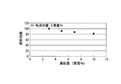
- test refractories were lined up on a rotating drum type erosion test apparatus (not shown), and the test slag having the slag composition shown in Table 2 was put into the test refractory while heating to 1700 ° C.
- the rotary erosion test was performed by rotating for 8 hours, and the height dimension (remaining dimension) of each test refractory lined was measured.
- the test slag was replaced with a new one every 20 minutes in the rotary drum erosion test apparatus.
- the wear index is the test number.
- the wear depth of the refractory No. 4 is indicated by an index of 100, and the smaller the numerical value, the less the wear.
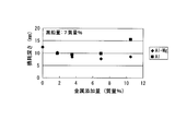
- Test No Using refractory raw materials for test of 4 to 7 and 9 to 11, kneading, molding and drying in the same manner as in the above rotary erosion test, and then cutting into a cylindrical shape of ⁇ 50 x 50 mm in height, the oxidation resistance A test refractory was obtained.
- the obtained test refractory is placed in an electric furnace (not shown) in a state of being buried in a coke breeze, heated to 1000 ° C. at a rate of temperature increase of 5 ° C./min, and pre-baked for 10 hours in a reducing atmosphere. It was. And after measuring the mass of each refractory for a test, the inside of the said electric furnace was made into atmospheric condition, and also oxidation baking for 4 hours was performed at 1400 degreeC.
- Test No. similar to that prepared in the above rotating erosion test.
- 9% by mass of graphite, 9% by mass of Al—Mg alloy, 2% by mass of phenol resin, and a refractory raw material for test (test No. 14) prepared as an MgO material; and 8% by mass of graphite, Al— Refractory raw material for test (test No.
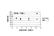
- test refractories were lined up and lined in a 50 kg vacuum melting furnace (not shown), and the test slag having the slag composition shown in Table 2 above was placed and heated to 1650 ° C., Simulating the degassing process, reducing the pressure to 1.3 kPa (10 Torr) and holding it for 3 hours, then measuring the height dimension (remaining dimension) of each test refractory lined to determine the wear depth. .
- the vacuum degassing tank 1 of the present embodiment shown in FIG. 6 includes iron skins 21 and 31 and refractories 22 and 32 that cover the insides of the iron skins 21 and 31, and degassed molten steel in a reduced-pressure atmosphere. I do.
- a carbon-containing magnesia refractory is lined at all or at least a contact portion with the molten slag among the refractories 22 and 32.
- the carbon-containing magnesia refractory includes 7% by mass or more and less than 28% graphite and 3.5% by mass or more and 14% by mass or less of an Al—Mg alloy,
- the mass ratio obtained by dividing the mass by the mass of the graphite is 0.5 or more and 2.0 or less, and the balance is composed of magnesia and inevitable impurities.
- the lower limit of the mass ratio is more preferably 1.0.
- the inevitable impurities in the present invention include binders such as phenol resins that are added in a small amount in the production process. The binder partially volatilizes during the drying process, but the remainder remains in the refractory.
- content of the said magnesia can be 58 mass% or more and less than 89.5 mass%.
- content of the said magnesia can be 58 mass% or more and less than 89.5 mass%.
- the upper limit of the graphite does not exceed 28% by mass, and when the Al—Mg alloy is 14% by mass, the mass ratio obtained by dividing the mass of the Al—Mg alloy by the mass of the graphite is The value is slightly over 0.5, and the remaining magnesia is 58% by mass or more, and when the graphite is 7% by mass and the Al—Mg alloy is 3.5% by mass, the Al This is because the mass ratio obtained by dividing the mass of the Mg alloy by the mass of the graphite is 0.5, and the remaining magnesia is less than 89.5 mass%.
- the vacuum degassing method of the present embodiment performs a vacuum degassing process using the vacuum degassing tank 1 having the above-described configuration so that a low basicity slag of CaO / SiO 2 ⁇ 2 is generated.
- the carbon-containing magnesia refractory of this embodiment contains 3.5 to 14% by mass of Al—Mg alloy powder, and the mass ratio with graphite is 0.5 or more. It has been confirmed that it exhibits excellent durability against low basicity slag and also exhibits extremely excellent durability even under reduced pressure such as degassing treatment. This overcomes the drawbacks of conventional carbon-containing magnesia refractories and greatly contributes to the improvement of the refractory life under the operating conditions of the degassing treatment of the steel industry.
Landscapes
- Engineering & Computer Science (AREA)
- Chemical & Material Sciences (AREA)
- Materials Engineering (AREA)
- Organic Chemistry (AREA)
- Ceramic Engineering (AREA)
- Metallurgy (AREA)
- Manufacturing & Machinery (AREA)
- Structural Engineering (AREA)
- Mechanical Engineering (AREA)
- General Engineering & Computer Science (AREA)
- Treatment Of Steel In Its Molten State (AREA)
- Compositions Of Oxide Ceramics (AREA)
- Furnace Housings, Linings, Walls, And Ceilings (AREA)
Abstract
Description
(a)本発明の一態様は、鉄皮と、この鉄皮の内部を覆う耐火物とを備え、減圧雰囲気で溶鋼の脱ガス処理を行う真空脱ガス槽であって、前記耐火物のうちの少なくとも溶融スラグとの接触部分に、炭素含有マグネシア質耐火物が設けられ;前記炭素含有マグネシア質耐火物は、7質量%以上かつ28%未満の黒鉛と、3.5質量%以上かつ14質量%以下のAl-Mg合金とを有してかつ、残部がマグネシア及び不可避的不純物からなり、前記Al-Mg合金の質量を前記黒鉛の質量で除算した質量比が0.5以上2.0以下である。
(b)上記(a)に記載の真空脱ガス槽では、前記質量比の下限値が1.0であってもよい。
(d)上記(c)に記載の真空脱ガス処理方法では、前記真空脱ガス槽中にSi又はSi合金を添加して鋼の二次精錬を行いながら、前記真空脱ガス処理を行ってもよい。
MgO(s)+C(s)→Mg(g)↑+CO(g)↑ ・・・(1)
また、上記炭素含有マグネシア質耐火物を真空脱ガス槽に内張りする際は、少なくとも溶融スラグと接触する部分にライニングすればよいが、内張り面の全てにライニングしても構わない。
図6に、本実施形態の真空脱ガス槽1を示す。この真空脱ガス槽1は、減圧雰囲気を利用して溶鋼の脱ガス処理を行う炉であり、上部槽2と下部槽3とを同軸に組み合わせて構成されている。上部槽2は、円筒状の鉄皮21とその内周面を覆う耐火物22とを備えている。上部槽2の上端は天蓋23で覆われている。また、上部槽2の側面には、合金投入口24及び排気口25が形成されている。
下部槽3は、上部槽2の鉄皮21と略同径の鉄皮31と、その内周面を覆う耐火物32とを備えている。下部槽3の下端には、2本の環流管33が鉛直方向に沿って設けられている。さらに、これら環流管33の下端に連なって2本の浸漬管4が取り付けられており、各浸漬管4は、取鍋5内の溶鋼に浸漬されている。
骨材となる粒径1~5mmかつ純度98%以上のマグネシアクリンカーと粒径1mm未満のマグネシア微粉とからなるMgO材、粒径100~400mmで純度97%以上の燐片状黒鉛、粒径40~200mmのAl-Mg合金粉末(組成Al12Mg17、純度99.0%以上)、粒径10~100mmの金属Al粉末(組成Al(金属Al)、純度99.5%以上)、及びフェノール樹脂を用いて、表1に示した試験No.1~12の試験用耐火物原料を用意した。さらに、黒鉛10質量%、Al-Mg合金4質量%、フェノール樹脂2質量%、及びMgO材82.30質量%を用いた試験用耐火物原料(試験No.16)を用意した。そして、各試験用耐火物原料をオムニミキサーで混錬した後、プレス機を用いて並型れんが(サイズ:65mm×114mm×230mm)に成形した。更に、この並型れんがを200℃で加熱乾燥し、上底41mm、下底67mm、高さ48.5mm、長さ114mmに切削して、回転試験用耐火物を得た。


試験No.4~7、9~11の試験用耐火物原料を用いて、上記回転侵食試験と同様にして混錬・成型・乾燥した後、φ50×高さ50mmの円柱状に切削して、耐酸化性試験用耐火物を得た。得られた試験用耐火物をコークブリーズ中に埋没させた状態で電気炉(不図示)に入れて、昇温速度5℃/分で1000℃に加熱し、還元雰囲気10時間の事前焼成を行なった。そして、各試験用耐火物の質量を測定した後、上記電気炉内を大気雰囲気にして、更に1400℃で4時間の酸化焼成を行なった。
上記回転侵食試験で用意したものと同様の試験No.4~7及び12の試験用耐火物原料と;黒鉛7質量%、Al-Mg合金14質量%、フェノール樹脂2質量%、及び残部をMgO材として準備した試験用耐火物原料(試験No.13)と;黒鉛9質量%、Al-Mg合金9質量%、フェノール樹脂2質量%、及び残部をMgO材として準備した試験用耐火物原料(試験No.14)と;黒鉛8質量%、Al-Mg合金8質量%、フェノール樹脂2質量%、及びMgO材80.36質量%として準備した試験用耐火物原料(試験No.15)と;を用意し、回転侵食試験と同様にして混錬・成型・乾燥した。そしてこの後、上底46mm、下底70mm、高さ30mm、長さ230mmのサイズに切削して、真空溶解炉侵食試験用サンプルを得た。得られた試験用耐火物を、50kg真空溶解炉(不図示)内にそれぞれ内張りして並べ、前述の表2に示すスラグ組成を有した試験用スラグを入れて、1650℃に加熱しながら、脱ガス処理を模擬して、1.3kPa(10Torr)まで減圧し、3時間保持した後、内張りした各試験用耐火物の高さ寸法(残寸法)を測定して、損耗深さを求めた。
図6に示した本実施形態の真空脱ガス槽1は、鉄皮21,31と、これら鉄皮21,31の内部を覆う耐火物22,32とを備え、減圧雰囲気で溶鋼の脱ガス処理を行う。そして、耐火物22,32のうちの全て又は少なくとも溶融スラグとの接触部分に、炭素含有マグネシア質耐火物がライニングされている。しかも、前記炭素含有マグネシア質耐火物は、7質量%以上かつ28%未満の黒鉛と、3.5質量%以上かつ14質量%以下のAl-Mg合金とを有し、前記Al-Mg合金の質量を前記黒鉛の質量で除算した質量比が0.5以上2.0以下でありかつ、残部がマグネシア及び不可避的不純物からなる。なお、前記質量比の下限値を1.0とすることがより好ましい。
また、本発明における不可避的不純物には、製造工程で少量添加されるフェノール樹脂等のバインダーも含まれる。バインダーは乾燥工程で一部揮発するが残部が耐火物中に残る。本発明においては、原料中に含まれる不可避的不純物だけでなく、このバインダーの残部も不可避的不純物として定義する。
なお、前記マグネシアの含有量は、58質量%以上かつ89.5質量%未満とすることができる。その理由は、前記黒鉛が28質量%を超えない上限値であり、前記Al-Mg合金が14質量%であった場合、前記Al-Mg合金の質量を前記黒鉛の質量で除算した質量比が0.5をわずかに超える値であり、残部となる前記マグネシアが58質量%以上となり、また、前記黒鉛が7質量%で前記Al-Mg合金が3.5質量%であった時は前記Al-Mg合金の質量を前記黒鉛の質量で除算した質量比が0.5であり、これより残部の前記マグネシアは89.5質量%未満となるためである。
21,31 鉄皮
22,32 耐火物
Claims (4)
- 鉄皮と、この鉄皮の内部を覆う耐火物とを備え、減圧雰囲気で溶鋼の脱ガス処理を行う真空脱ガス槽であって、
前記耐火物のうちの少なくとも溶融スラグとの接触部分に、炭素含有マグネシア質耐火物が設けられ;
前記炭素含有マグネシア質耐火物は、7質量%以上かつ28%未満の黒鉛と、3.5質量%以上かつ14質量%以下のAl-Mg合金とを有してかつ、残部がマグネシア及び不可避的不純物からなり、前記Al-Mg合金の質量を前記黒鉛の質量で除算した質量比が0.5以上2.0以下である;
ことを特徴とする真空脱ガス槽。 - 前記質量比の下限値が1.0であることを特徴とする請求項1に記載の真空脱ガス槽。
- 請求項1または2に記載の真空脱ガス槽を用いて、CaO/SiO2≦2の低塩基度スラグが生成するような真空脱ガス処理を行うことを特徴とする真空脱ガス処理方法。
- 前記真空脱ガス槽中にSi又はSi合金を添加して鋼の二次精錬を行いながら、前記真空脱ガス処理を行うことを特徴とする請求項3に記載の真空脱ガス処理方法。
Priority Applications (5)
| Application Number | Priority Date | Filing Date | Title |
|---|---|---|---|
| CN201180070369.4A CN103492344B (zh) | 2011-04-27 | 2011-04-27 | 真空脱气槽及采用真空脱气槽的脱气处理方法 |
| JP2011544715A JP5068887B1 (ja) | 2011-04-27 | 2011-04-27 | 真空脱ガス槽及びこれを用いた脱ガス処理方法 |
| BR112013027385-2A BR112013027385B1 (pt) | 2011-04-27 | 2011-04-27 | Tanque de desgaseificação a vácuo e método de desgaseificação utilizando o mesmo |
| KR1020137028568A KR101403131B1 (ko) | 2011-04-27 | 2011-04-27 | 진공 탈가스조 및 이것을 사용한 탈가스 처리 방법 |
| PCT/JP2011/060278 WO2012147180A1 (ja) | 2011-04-27 | 2011-04-27 | 真空脱ガス槽及びこれを用いた脱ガス処理方法 |
Applications Claiming Priority (1)
| Application Number | Priority Date | Filing Date | Title |
|---|---|---|---|
| PCT/JP2011/060278 WO2012147180A1 (ja) | 2011-04-27 | 2011-04-27 | 真空脱ガス槽及びこれを用いた脱ガス処理方法 |
Publications (1)
| Publication Number | Publication Date |
|---|---|
| WO2012147180A1 true WO2012147180A1 (ja) | 2012-11-01 |
Family
ID=47071722
Family Applications (1)
| Application Number | Title | Priority Date | Filing Date |
|---|---|---|---|
| PCT/JP2011/060278 Ceased WO2012147180A1 (ja) | 2011-04-27 | 2011-04-27 | 真空脱ガス槽及びこれを用いた脱ガス処理方法 |
Country Status (5)
| Country | Link |
|---|---|
| JP (1) | JP5068887B1 (ja) |
| KR (1) | KR101403131B1 (ja) |
| CN (1) | CN103492344B (ja) |
| BR (1) | BR112013027385B1 (ja) |
| WO (1) | WO2012147180A1 (ja) |
Cited By (1)
| Publication number | Priority date | Publication date | Assignee | Title |
|---|---|---|---|---|
| JP2021155801A (ja) * | 2020-03-26 | 2021-10-07 | 日本製鉄株式会社 | 真空脱ガス装置用スピネル−マグネシア−カーボン煉瓦及び真空脱ガス装置 |
Citations (4)
| Publication number | Priority date | Publication date | Assignee | Title |
|---|---|---|---|---|
| JPH0839214A (ja) * | 1994-07-30 | 1996-02-13 | Kurosaki Refract Co Ltd | 連続鋳造用ノズル |
| JP2000001363A (ja) * | 1998-06-09 | 2000-01-07 | Nippon Steel Corp | 耐火物内張り |
| JP2007076980A (ja) * | 2005-09-16 | 2007-03-29 | Kurosaki Harima Corp | マグネシアカーボンれんが |
| JP2009137768A (ja) * | 2007-12-03 | 2009-06-25 | Nippon Steel Corp | Alまたは/及びAl−Mg合金添加MgO―Cれんがのマイクロ波熱処理方法、及びAlまたは/及びAl−Mg合金添加MgO―Cれんが |
Family Cites Families (15)
| Publication number | Priority date | Publication date | Assignee | Title |
|---|---|---|---|---|
| JPS602269B2 (ja) * | 1978-06-16 | 1985-01-21 | 旭硝子株式会社 | 炭素含有不焼成耐火物の製造方法 |
| JPS602269A (ja) * | 1983-06-20 | 1985-01-08 | 日新化成株式会社 | 競艇場用緩衝消波装置 |
| JPH01162714A (ja) * | 1987-12-18 | 1989-06-27 | Kawasaki Steel Corp | 転炉 |
| JPH05132354A (ja) * | 1991-11-11 | 1993-05-28 | Kawasaki Refract Co Ltd | 不焼成マグネシア・カーボンれんが |
| JPH08133822A (ja) * | 1994-11-08 | 1996-05-28 | Nisshin Steel Co Ltd | ステンレス鋼精錬取鍋用不焼成炭素含有煉瓦及びステンレス鋼精錬用取鍋 |
| JPH10218658A (ja) * | 1997-02-03 | 1998-08-18 | Kurosaki Refract Co Ltd | 耐酸化性付与炭素含有耐火物 |
| JPH10279370A (ja) * | 1997-04-03 | 1998-10-20 | Kawasaki Steel Corp | 高炉主樋用不定形耐火材料 |
| JP2000001375A (ja) * | 1998-06-09 | 2000-01-07 | Nippon Steel Corp | 鉄鋼精錬用浸漬構造体 |
| JP4085483B2 (ja) * | 1998-09-03 | 2008-05-14 | Jfeスチール株式会社 | ステンレス鋼の連続鋳造方法 |
| JP2001097782A (ja) * | 1999-10-01 | 2001-04-10 | Nippon Steel Corp | マグネシア−炭素質不焼成れんが及びそれを内張りしてなる溶融金属容器 |
| CN1508091A (zh) * | 2002-12-20 | 2004-06-30 | 上海科鸣机械设备有限公司 | 一种直流电弧炉炉底耐火材料 |
| ES2609510T3 (es) * | 2006-11-06 | 2017-04-20 | Krosakiharima Corporation | Ladrillos de manga resistentes |
| CN101784859B (zh) * | 2007-08-27 | 2011-12-07 | 新日本制铁株式会社 | 铁浴式熔融还原炉 |
| JP2010132516A (ja) * | 2008-12-08 | 2010-06-17 | Nippon Steel Corp | マグネシアカーボンれんが及びその製造方法 |
| CN201793628U (zh) * | 2010-09-08 | 2011-04-13 | 鞍钢股份有限公司 | 新型环流管 |
-
2011
- 2011-04-27 WO PCT/JP2011/060278 patent/WO2012147180A1/ja not_active Ceased
- 2011-04-27 KR KR1020137028568A patent/KR101403131B1/ko not_active Expired - Fee Related
- 2011-04-27 JP JP2011544715A patent/JP5068887B1/ja not_active Expired - Fee Related
- 2011-04-27 BR BR112013027385-2A patent/BR112013027385B1/pt not_active IP Right Cessation
- 2011-04-27 CN CN201180070369.4A patent/CN103492344B/zh not_active Expired - Fee Related
Patent Citations (4)
| Publication number | Priority date | Publication date | Assignee | Title |
|---|---|---|---|---|
| JPH0839214A (ja) * | 1994-07-30 | 1996-02-13 | Kurosaki Refract Co Ltd | 連続鋳造用ノズル |
| JP2000001363A (ja) * | 1998-06-09 | 2000-01-07 | Nippon Steel Corp | 耐火物内張り |
| JP2007076980A (ja) * | 2005-09-16 | 2007-03-29 | Kurosaki Harima Corp | マグネシアカーボンれんが |
| JP2009137768A (ja) * | 2007-12-03 | 2009-06-25 | Nippon Steel Corp | Alまたは/及びAl−Mg合金添加MgO―Cれんがのマイクロ波熱処理方法、及びAlまたは/及びAl−Mg合金添加MgO―Cれんが |
Cited By (2)
| Publication number | Priority date | Publication date | Assignee | Title |
|---|---|---|---|---|
| JP2021155801A (ja) * | 2020-03-26 | 2021-10-07 | 日本製鉄株式会社 | 真空脱ガス装置用スピネル−マグネシア−カーボン煉瓦及び真空脱ガス装置 |
| JP7389352B2 (ja) | 2020-03-26 | 2023-11-30 | 日本製鉄株式会社 | 真空脱ガス装置用スピネル-マグネシア-カーボン煉瓦及び真空脱ガス装置 |
Also Published As
| Publication number | Publication date |
|---|---|
| KR20130126748A (ko) | 2013-11-20 |
| KR101403131B1 (ko) | 2014-06-03 |
| BR112013027385B1 (pt) | 2020-03-03 |
| JPWO2012147180A1 (ja) | 2014-07-28 |
| CN103492344A (zh) | 2014-01-01 |
| CN103492344B (zh) | 2016-06-29 |
| BR112013027385A2 (pt) | 2017-01-17 |
| JP5068887B1 (ja) | 2012-11-07 |
Similar Documents
| Publication | Publication Date | Title |
|---|---|---|
| TWI606993B (zh) | 鎂碳磚 | |
| TWI650300B (zh) | 氧化鎂碳磚及其製造方法 | |
| JP5777561B2 (ja) | ステンレス鋼精錬取鍋用煉瓦及びステンレス鋼精錬取鍋 | |
| JP6600729B1 (ja) | 真空脱ガス装置用スピネル−マグネシア−カーボンれんが及びこれを下部槽側壁にライニングした真空脱ガス装置 | |
| JPH11189477A (ja) | 混銑車用の黒鉛含有不定形耐火物材料 | |
| JP5967160B2 (ja) | 減圧を伴う二次精錬設備用内張り耐火物 | |
| JP7416117B2 (ja) | キャスタブル耐火物および溶鋼鍋 | |
| JP5068887B1 (ja) | 真空脱ガス槽及びこれを用いた脱ガス処理方法 | |
| JP2022056100A (ja) | マグクロれんがの製造方法 | |
| JP6194257B2 (ja) | マグネシアカーボンれんが | |
| JP7389352B2 (ja) | 真空脱ガス装置用スピネル-マグネシア-カーボン煉瓦及び真空脱ガス装置 | |
| JP6315037B2 (ja) | 連続鋳造用タンディッシュ用内張り耐火物 | |
| JP7481982B2 (ja) | マグクロれんがの製造方法 | |
| JP5920412B2 (ja) | 連続鋳造ノズル | |
| JP2024008662A (ja) | マグネシアカーボンれんが及びその製造方法 | |
| JP2009242122A (ja) | 高炉炉床用れんが及びこれをライニングした高炉炉床 | |
| JP5928168B2 (ja) | フェロマンガンスラグ回収用取鍋およびフェロマンガンスラグ回収用取鍋の使用方法 | |
| JP2011084450A (ja) | 炭素含有マグネシア質耐火物及びこれを用いた脱ガス処理方法 | |
| JP5578680B2 (ja) | 炭素含有耐火物 | |
| JP7614501B2 (ja) | 真空脱ガス装置用マグネシア-スピネル煉瓦及び真空脱ガス装置 | |
| JP7469667B2 (ja) | 真空脱ガス装置用スピネル-アルミナ-カーボン煉瓦及び真空脱ガス装置 | |
| JP5388305B2 (ja) | セミリボンドマグネシア−クロムれんが | |
| JP2006076863A (ja) | マグネシア−クロム−窒化硼素質不焼成耐火物 | |
| JP2872670B2 (ja) | 溶融金属容器ライニング用不定形耐火物 | |
| JP2018012618A (ja) | マグネシア−クロム質煉瓦の製造方法並びに使用方法 |
Legal Events
| Date | Code | Title | Description |
|---|---|---|---|
| ENP | Entry into the national phase |
Ref document number: 2011544715 Country of ref document: JP Kind code of ref document: A |
|
| 121 | Ep: the epo has been informed by wipo that ep was designated in this application |
Ref document number: 11864395 Country of ref document: EP Kind code of ref document: A1 |
|
| NENP | Non-entry into the national phase |
Ref country code: DE |
|
| ENP | Entry into the national phase |
Ref document number: 20137028568 Country of ref document: KR Kind code of ref document: A |
|
| REG | Reference to national code |
Ref country code: BR Ref legal event code: B01A Ref document number: 112013027385 Country of ref document: BR |
|
| 122 | Ep: pct application non-entry in european phase |
Ref document number: 11864395 Country of ref document: EP Kind code of ref document: A1 |
|
| ENP | Entry into the national phase |
Ref document number: 112013027385 Country of ref document: BR Kind code of ref document: A2 Effective date: 20131024 |