WO2012147147A1 - タンク、該タンクを用いた研磨パッドの製造方法 - Google Patents
タンク、該タンクを用いた研磨パッドの製造方法 Download PDFInfo
- Publication number
- WO2012147147A1 WO2012147147A1 PCT/JP2011/060046 JP2011060046W WO2012147147A1 WO 2012147147 A1 WO2012147147 A1 WO 2012147147A1 JP 2011060046 W JP2011060046 W JP 2011060046W WO 2012147147 A1 WO2012147147 A1 WO 2012147147A1
- Authority
- WO
- WIPO (PCT)
- Prior art keywords
- tank
- polishing pad
- resin composition
- polishing
- polyurethane resin
- Prior art date
- Legal status (The legal status is an assumption and is not a legal conclusion. Google has not performed a legal analysis and makes no representation as to the accuracy of the status listed.)
- Ceased
Links
Images




Classifications
-
- B—PERFORMING OPERATIONS; TRANSPORTING
- B24—GRINDING; POLISHING
- B24B—MACHINES, DEVICES, OR PROCESSES FOR GRINDING OR POLISHING; DRESSING OR CONDITIONING OF ABRADING SURFACES; FEEDING OF GRINDING, POLISHING, OR LAPPING AGENTS
- B24B37/00—Lapping machines or devices; Accessories
- B24B37/11—Lapping tools
- B24B37/20—Lapping pads for working plane surfaces
- B24B37/24—Lapping pads for working plane surfaces characterised by the composition or properties of the pad materials
-
- B—PERFORMING OPERATIONS; TRANSPORTING
- B24—GRINDING; POLISHING
- B24B—MACHINES, DEVICES, OR PROCESSES FOR GRINDING OR POLISHING; DRESSING OR CONDITIONING OF ABRADING SURFACES; FEEDING OF GRINDING, POLISHING, OR LAPPING AGENTS
- B24B37/00—Lapping machines or devices; Accessories
- B24B37/04—Lapping machines or devices; Accessories designed for working plane surfaces
- B24B37/042—Lapping machines or devices; Accessories designed for working plane surfaces operating processes therefor
-
- B—PERFORMING OPERATIONS; TRANSPORTING
- B29—WORKING OF PLASTICS; WORKING OF SUBSTANCES IN A PLASTIC STATE IN GENERAL
- B29C—SHAPING OR JOINING OF PLASTICS; SHAPING OF MATERIAL IN A PLASTIC STATE, NOT OTHERWISE PROVIDED FOR; AFTER-TREATMENT OF THE SHAPED PRODUCTS, e.g. REPAIRING
- B29C39/00—Shaping by casting, i.e. introducing the moulding material into a mould or between confining surfaces without significant moulding pressure; Apparatus therefor
- B29C39/003—Shaping by casting, i.e. introducing the moulding material into a mould or between confining surfaces without significant moulding pressure; Apparatus therefor characterised by the choice of material
- B29C39/006—Monomers or prepolymers
-
- B—PERFORMING OPERATIONS; TRANSPORTING
- B29—WORKING OF PLASTICS; WORKING OF SUBSTANCES IN A PLASTIC STATE IN GENERAL
- B29C—SHAPING OR JOINING OF PLASTICS; SHAPING OF MATERIAL IN A PLASTIC STATE, NOT OTHERWISE PROVIDED FOR; AFTER-TREATMENT OF THE SHAPED PRODUCTS, e.g. REPAIRING
- B29C39/00—Shaping by casting, i.e. introducing the moulding material into a mould or between confining surfaces without significant moulding pressure; Apparatus therefor
- B29C39/02—Shaping by casting, i.e. introducing the moulding material into a mould or between confining surfaces without significant moulding pressure; Apparatus therefor for making articles of definite length, i.e. discrete articles
-
- B—PERFORMING OPERATIONS; TRANSPORTING
- B29—WORKING OF PLASTICS; WORKING OF SUBSTANCES IN A PLASTIC STATE IN GENERAL
- B29C—SHAPING OR JOINING OF PLASTICS; SHAPING OF MATERIAL IN A PLASTIC STATE, NOT OTHERWISE PROVIDED FOR; AFTER-TREATMENT OF THE SHAPED PRODUCTS, e.g. REPAIRING
- B29C39/00—Shaping by casting, i.e. introducing the moulding material into a mould or between confining surfaces without significant moulding pressure; Apparatus therefor
- B29C39/22—Component parts, details or accessories; Auxiliary operations
- B29C39/24—Feeding the material into the mould
-
- B—PERFORMING OPERATIONS; TRANSPORTING
- B29—WORKING OF PLASTICS; WORKING OF SUBSTANCES IN A PLASTIC STATE IN GENERAL
- B29C—SHAPING OR JOINING OF PLASTICS; SHAPING OF MATERIAL IN A PLASTIC STATE, NOT OTHERWISE PROVIDED FOR; AFTER-TREATMENT OF THE SHAPED PRODUCTS, e.g. REPAIRING
- B29C44/00—Shaping by internal pressure generated in the material, e.g. swelling or foaming ; Producing porous or cellular expanded plastics articles
- B29C44/34—Auxiliary operations
- B29C44/36—Feeding the material to be shaped
- B29C44/38—Feeding the material to be shaped into a closed space, i.e. to make articles of definite length
-
- B—PERFORMING OPERATIONS; TRANSPORTING
- B65—CONVEYING; PACKING; STORING; HANDLING THIN OR FILAMENTARY MATERIAL
- B65D—CONTAINERS FOR STORAGE OR TRANSPORT OF ARTICLES OR MATERIALS, e.g. BAGS, BARRELS, BOTTLES, BOXES, CANS, CARTONS, CRATES, DRUMS, JARS, TANKS, HOPPERS, FORWARDING CONTAINERS; ACCESSORIES, CLOSURES, OR FITTINGS THEREFOR; PACKAGING ELEMENTS; PACKAGES
- B65D25/00—Details of other kinds or types of rigid or semi-rigid containers
- B65D25/02—Internal fittings
- B65D25/04—Partitions
-
- B—PERFORMING OPERATIONS; TRANSPORTING
- B65—CONVEYING; PACKING; STORING; HANDLING THIN OR FILAMENTARY MATERIAL
- B65D—CONTAINERS FOR STORAGE OR TRANSPORT OF ARTICLES OR MATERIALS, e.g. BAGS, BARRELS, BOTTLES, BOXES, CANS, CARTONS, CRATES, DRUMS, JARS, TANKS, HOPPERS, FORWARDING CONTAINERS; ACCESSORIES, CLOSURES, OR FITTINGS THEREFOR; PACKAGING ELEMENTS; PACKAGES
- B65D7/00—Containers having bodies formed by interconnecting or uniting two or more rigid, or substantially rigid, components made wholly or mainly of metal
- B65D7/02—Containers having bodies formed by interconnecting or uniting two or more rigid, or substantially rigid, components made wholly or mainly of metal characterised by shape
- B65D7/04—Containers having bodies formed by interconnecting or uniting two or more rigid, or substantially rigid, components made wholly or mainly of metal characterised by shape of curved cross-section, e.g. cans of circular or elliptical cross-section
-
- H—ELECTRICITY
- H10—SEMICONDUCTOR DEVICES; ELECTRIC SOLID-STATE DEVICES NOT OTHERWISE PROVIDED FOR
- H10P—GENERIC PROCESSES OR APPARATUS FOR THE MANUFACTURE OR TREATMENT OF DEVICES COVERED BY CLASS H10
- H10P52/00—Grinding, lapping or polishing of wafers, substrates or parts of devices
-
- B—PERFORMING OPERATIONS; TRANSPORTING
- B29—WORKING OF PLASTICS; WORKING OF SUBSTANCES IN A PLASTIC STATE IN GENERAL
- B29K—INDEXING SCHEME ASSOCIATED WITH SUBCLASSES B29B, B29C OR B29D, RELATING TO MOULDING MATERIALS OR TO MATERIALS FOR MOULDS, REINFORCEMENTS, FILLERS OR PREFORMED PARTS, e.g. INSERTS
- B29K2075/00—Use of PU, i.e. polyureas or polyurethanes or derivatives thereof, as moulding material
-
- B—PERFORMING OPERATIONS; TRANSPORTING
- B29—WORKING OF PLASTICS; WORKING OF SUBSTANCES IN A PLASTIC STATE IN GENERAL
- B29L—INDEXING SCHEME ASSOCIATED WITH SUBCLASS B29C, RELATING TO PARTICULAR ARTICLES
- B29L2031/00—Other particular articles
- B29L2031/736—Grinding or polishing equipment
Definitions
- the present invention relates to a tank for containing a resin composition, and more particularly to a tank used for producing a polishing pad from a resin composition having a high viscosity or a high thixotropic property.
- the present invention is a flattening process for optical materials such as lenses and reflection mirrors, silicon wafers, glass substrates for hard disks, aluminum substrates, and materials that require high surface flatness such as general metal polishing. It is related with the manufacturing method of the polishing pad which can be performed stably and with high polishing efficiency.
- the polishing pad of the present invention is particularly suitable for a step of planarizing a silicon wafer and a device having an oxide layer, a metal layer, etc. formed thereon, before further laminating and forming these oxide layers and metal layers. Used for.
- a typical material that requires a high degree of surface flatness is a single crystal silicon disk called a silicon wafer for manufacturing a semiconductor integrated circuit (IC, LSI).
- Silicon wafers have a highly accurate surface in each process of stacking and forming oxide layers and metal layers in order to form reliable semiconductor junctions of various thin films used for circuit formation in IC, LSI, and other manufacturing processes. It is required to finish flat.
- a polishing pad is generally fixed to a rotatable support disk called a platen, and a workpiece such as a semiconductor wafer is fixed to a polishing head.
- a polishing operation is performed by generating a relative speed between the platen and the polishing head by both movements, and continuously supplying a polishing slurry containing abrasive grains onto the polishing pad.
- the polishing pad one made of polyurethane foam is preferably used, and as a method for producing the polyurethane foam, for example, the following method has been proposed.
- a polyurethane foam is provided by providing a mold at the bottom of the tank, injecting a polyurethane foam-forming composition from the valve provided at the bottom into the mold, and reacting and curing the injected polyurethane foam-forming composition.
- Patent Document 1 There has been proposed a method for manufacturing (Patent Document 1).
- a resin molded body comprising: a first step of charging a stock solution for forming a resin molded body into a tank; and a second step of pouring the stock solution for forming a resin molded body into the tank into a mold and curing it.
- the first step is performed in a state where an opening formed on a side surface of the tank is closed with a door member.
- the door member is opened to open the opening.
- a method for producing a resin molded body is proposed in which a stock solution for forming a resin molded body is poured into the mold placed below the opening (Patent Document 2).
- Patent Document 2 also has a problem that air voids are likely to occur when the stock solution for forming a resin molding is poured into a mold when the stock solution for forming a resin molding has high viscosity or high thixotropic properties. There is. Moreover, since the raw material adhering to the inner wall of the door member is easily dropped on the liquid surface, there is also a problem that a quality defect of the resin molded body tends to occur.
- An object of the present invention is to provide a tank used for producing a quality polishing pad free of air voids, a method for producing a polishing pad using the tank, and a polishing pad obtained by the production method. . Moreover, it aims at providing the manufacturing method of the semiconductor device using this polishing pad.
- the present inventors have found that the above object can be achieved by the following tank and manufacturing method, and have completed the present invention.
- the present invention is a tank for storing a resin composition, wherein the tank is configured by connecting two or more body members in a frame shape via a connecting portion, and is connected at least at one place.
- the part is provided with an opening / closing member for connecting adjacent body members so as to be able to open both sides, and at least one other connection part is provided with a connection member for connecting adjacent body members in the form of an open door.
- the tank of the present invention is configured by connecting two or more body members in a frame shape via a connecting portion. At least one connecting portion is provided with an opening / closing member that connects adjacent fuselage members so as to be able to open both sides, and at least one other connecting portion is formed such that adjacent fuselage members are in the form of a hinged door.
- a connecting member to be connected is provided. According to this configuration, since the opening and closing member can be opened and the adjacent body members can be moved to open both sides, if the tank is installed in the casting mold, the resin composition accommodated in the tank is stored in the tank. It becomes possible to cast into the casting mold from the side surface of the mold.
- the present invention is configured by connecting three body members in a cylindrical shape via a connection part, and adjacent body members are connected to one connection part so that they can be double-opened.
- An opening / closing member is provided, and a tank provided with a connecting member for connecting adjacent body members in the form of an open door can be cited as the other two connecting portions.
- the number of body members and connecting portions is small, but when the tank is configured by connecting two body members in a cylindrical shape via the connecting portions, It is difficult to fix the tank in the casting mold when the opening and closing member is opened and the adjacent body members are moved to open both sides, and the manufacturing process becomes complicated.
- the tank when the tank is configured by connecting three body members in a cylindrical shape via the connecting portion, the remaining one body member is opened when the opening and closing member is opened and the adjacent body members are moved to open both sides. Can be fixed in the casting mold, which is convenient in the manufacturing process.
- this invention is a manufacturing method of the polishing pad including the process of producing the grinding
- the said process is the process of accommodating a polyurethane resin composition in the said tank installed in the casting mold ( A) opening the opening / closing member provided in the tank and moving the adjacent body members in a double-open manner to cast the polyurethane resin composition in the tank into the casting mold (B),
- the present invention relates to a method for producing a polishing pad comprising a step (C) of producing a polyurethane resin by curing a stretched polyurethane resin composition.
- the polyurethane resin composition in the tank can be cast without generating air voids in the casting mold by a simple operation. Can be made.
- the raw material adhering to the inner wall of the tank is difficult to be mixed into the polyurethane resin composition in the casting mold. As a result, a high quality polishing pad can be manufactured.
- the first component containing the isocyanate group-containing compound and the silicon-based surfactant is stirred in the presence of a non-reactive gas in the tank, and the non-reactive gas is dispersed as fine bubbles to generate bubbles.
- It may be a step of preparing a dispersion and preparing a polyurethane resin composition by containing a second component containing an active hydrogen group-containing compound in the prepared cell dispersion. According to this method, a polishing pad made of a polyurethane foam having fine bubbles can be produced without using hollow beads or the like.
- the present invention relates to a semiconductor device manufacturing method including a step of polishing a surface of a semiconductor wafer using the polishing pad.
- FIG. 7A is a schematic cross-sectional view taken along the line A-A ′ of FIG.
- FIG. 8A is a schematic cross-sectional view taken along the line A-A 'of FIG.
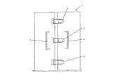
- FIG. 1a is a plan view schematically showing a configuration of a tank according to the present invention.
- FIG. 1 b is a front view schematically showing the configuration of the tank according to the present invention.
- the tank 1 is configured by connecting two or more body members 2 in a frame shape via a connection portion 3, and at least one connection portion 3 can open two adjacent body members 2 to each other.
- An opening / closing member 4 to be connected is provided, and at least one other connecting portion 3 is provided with a connecting member 5 for connecting adjacent body members 2 to each other in the form of an open door.
- FIG. 1 a shows a tank 1 configured by connecting three body members 2 in a cylindrical shape via a connecting portion 3.
- the tank 1 is preferably cylindrical, but may be triangular, quadrangular, or polygonal. Moreover, when the tank 1 is cylindrical, it is preferable that it is comprised by the three trunk
- the tank 1 is preferably bottomless, but may be bottomed.
- the opening / closing member 4 is provided to maintain a closed state.
- the body member 2 provided with the opening and closing member 4 may be provided with a handle member 6 for facilitating opening and closing of the body member 2.
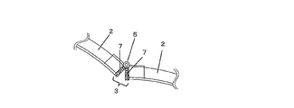
- FIG. 2a and FIG. 3a are schematic views showing the configuration when the connecting portion of the tank according to the present invention is opened.
- 2b and 3b are schematic views showing a configuration when the connecting portion of the tank according to the present invention is closed.
- the connecting portion 3 is provided with a connecting member 5 such as a hinge that connects adjacent body members 2 in an open door shape.
- the connecting portion 3 is provided with a seal member 7 such as a foam or a non-foam, and a surface seal or a line (dot) using the elastic deformation of the seal member 7. It is preferable to have a structure for sealing.
- the inner diameter of the tank 1 is preferably about several times the outer diameter of the mixer blades, and the height of the tank 1 is preferably set so that the resin composition stirred by the mixer does not overflow.
- the capacity of the tank 1 is not particularly limited, but is usually about 2 to 90 liters.
- the tank of the present invention may include a mixer for preparing the resin composition.
- FIG. 4a and 5a are schematic cross-sectional views showing a state before a bottomless tank is installed in a casting mold.
- 4b and 5b are schematic cross-sectional views showing the state after the bottomless tank is installed in the casting mold.
- an auxiliary member 8 for facilitating installation of the tank on the surface of the casting mold 12 is provided on the outer peripheral surface of the bottom of the tank.
- the auxiliary member 8 is preferably provided with a sealing member 9 such as a foam or a non-foamed body in order to prevent liquid leakage from the bottom.
- the seal member 9 may be provided directly at the bottom of the tank.
- a seal member 9 may be provided on the surface of the casting mold 12. As shown in FIG. 4b and FIG. 5b, by installing the tank in the casting mold, the seal member 9 is elastically deformed to be face-sealed or line (dot) sealed.
- the auxiliary member 8 of the two body members 2 that are double-opened includes a frictional resistance reducing member 10 such as a fluororesin plate in order to reduce the frictional resistance between the bottom surface of the body member and the casting mold surface during opening and closing. It is preferable to be provided.
- the resin composition is accommodated in a tank installed in the casting mold.
- the resin composition may be prepared in the tank by charging each raw material into the tank and stirring and mixing, or a resin composition prepared in advance may be charged in the tank.
- the resin for constituting the polishing pad is not particularly limited.
- polyurethane resin polyurethane resin, polyester resin, polyamide resin, acrylic resin, polycarbonate resin, halogen resin (polyvinyl chloride, polytetrafluoroethylene, polyfluoride) Vinylidene, etc.), polystyrene, olefin resins (polyethylene, polypropylene, etc.), epoxy resins, photosensitive resins, and mixtures thereof.
- Polyurethane resin is particularly preferred as a polishing pad forming material because it is excellent in abrasion resistance and a polymer having desired physical properties can be easily obtained by variously changing the raw material composition.
- the resin for constituting the polishing pad (polishing layer) is a polyurethane resin will be described.
- the polyurethane resin is composed of an isocyanate component, a polyol component (high molecular weight polyol, low molecular weight polyol, etc.), and a chain extender.
- isocyanate component a known compound in the field of polyurethane can be used without particular limitation.
- isocyanate component 2,4-toluene diisocyanate, 2,6-toluene diisocyanate, 2,2′-diphenylmethane diisocyanate, 2,4′-diphenylmethane diisocyanate, 4,4′-diphenylmethane diisocyanate, 1,5-naphthalene diisocyanate, Aromatic diisocyanates such as p-phenylene diisocyanate, m-phenylene diisocyanate, p-xylylene diisocyanate, m-xylylene diisocyanate; ethylene diisocyanate, 2,2,4-trimethylhexamethylene diisocyanate, 1,6-hexamethylene diisocyanate, etc.
- Aliphatic diisocyanate 1,4-cyclohexane diisocyanate, 4,4'-dicyclohexylmethane diisocyanate, isophorone diisocyanate Isocyanate, alicyclic diisocyanates such as norbornane diisocyanate. These may be used alone or in combination of two or more.
- the isocyanate component a trifunctional or higher polyfunctional polyisocyanate compound can be used in addition to the diisocyanate compound.
- the polyfunctional isocyanate compound a series of diisocyanate adduct compounds are commercially available as Desmodur-N (manufactured by Bayer) and trade name Duranate (manufactured by Asahi Kasei Kogyo).
- high molecular weight polyol examples include polyether polyols typified by polytetramethylene ether glycol, polyester polyols typified by polybutylene adipate, polycaprolactone polyol, and a reaction product of a polyester glycol such as polycaprolactone and alkylene carbonate.
- low molecular weight polyamines such as ethylenediamine, tolylenediamine, diphenylmethanediamine, and diethylenetriamine
- alcohol amines such as monoethanolamine, 2- (2-aminoethylamino) ethanol, and monopropanolamine can be used in combination.
- These low molecular weight polyols and low molecular weight polyamines may be used alone or in combination of two or more.
- a chain extender is used for curing the prepolymer.
- the chain extender is an organic compound having at least two active hydrogen groups, and examples of the active hydrogen group include a hydroxyl group, a primary or secondary amino group, and a thiol group (SH).
- the ratio of the isocyanate component, polyol component, and chain extender can be variously changed depending on the molecular weight of each, the desired physical properties of the polishing pad, and the like.
- Polyurethane resin can be produced by either the prepolymer method or the one-shot method, but a prepolymer method in which an isocyanate-terminated prepolymer is synthesized in advance from an isocyanate component and a polyol component and then reacted with a chain extender.
- the obtained polyurethane resin has excellent physical properties and is suitable.
- the polyurethane resin is produced by mixing and curing a first component containing an isocyanate group-containing compound and a second component containing an active hydrogen group-containing compound.
- the isocyanate-terminated prepolymer becomes an isocyanate group-containing compound
- the chain extender becomes an active hydrogen group-containing compound.
- the isocyanate component becomes an isocyanate group-containing compound
- the chain extender and the polyol component become active hydrogen group-containing compounds.
- the polyurethane resin may be a foam or a non-foam, but is preferably a foam in consideration of the polishing characteristics of the polishing pad.
- Examples of the polyurethane foam production method include a method of adding hollow beads, a mechanical foaming method, a chemical foaming method, and the like.
- a mechanical foaming method using a silicon surfactant which is a copolymer of polyalkylsiloxane and polyether is preferable.
- suitable silicon surfactants include SH-192 and L-5340 (manufactured by Toray Dow Corning Silicone), B8465 (manufactured by Goldschmidt), and the like.
- stimulates polyurethane reactions such as a tertiary amine type, stabilizers, such as antioxidant, a lubricant, a pigment, a filler, an antistatic agent, and other additives as needed.
- a first component containing an isocyanate group-containing compound and a silicon-based surfactant is stirred in the presence of a non-reactive gas in a tank, and the non-reactive gas is dispersed as fine bubbles to prepare a bubble dispersion.
- the 2nd component containing an active hydrogen group containing compound is added to the prepared bubble dispersion liquid, and it stirs and mixes, and prepares a foaming type polyurethane resin composition.
- non-reactive gas used to form the fine bubbles non-flammable gases are preferable, and specific examples include nitrogen, oxygen, carbon dioxide, rare gases such as helium and argon, and mixed gases thereof. In view of cost, it is most preferable to use air that has been dried to remove moisture.
- a known stirring device can be used without particular limitation as a stirring device for making non-reactive gas into fine bubbles and dispersing it in the first component.
- a homogenizer e.g., a homogenizer, a dissolver, a two-axis planetary mixer (planetary) Mixer) and the like.
- the shape of the stirring blade of the stirring device is not particularly limited, however, it is preferable to use a whipper-type stirring blade because fine bubbles can be obtained.
- the stirring for preparing the bubble dispersion and the stirring for adding and mixing the second component use different stirring devices.
- the stirring for adding and mixing the second component may not be stirring for forming bubbles, and it is preferable to use a stirring device that does not involve large bubbles.
- a planetary mixer is suitable.
- the same stirring device may be used as the stirring device for the foaming step and the mixing step, and it is preferable to adjust the stirring conditions such as adjusting the rotational speed of the stirring blade as necessary.
- the opening / closing member provided in the tank is opened, and the adjacent body members are moved in a double-open manner to cast the polyurethane resin composition in the tank into the casting mold.
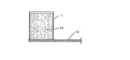
- FIG. 6a is a schematic plan view showing a state in which a tank containing a polyurethane resin composition is installed in a casting mold.
- 6b is a schematic cross-sectional view taken along the line A-A 'of FIG. 6a.
- the tank 1 is configured by connecting three body members in a cylindrical shape via a connecting portion.
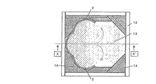
- FIG. 7a is a schematic plan view showing a state in which the polyurethane resin composition in the tank is cast into the casting mold by moving the adjacent body members in a double-open manner.
- FIG. 7b is a schematic cross-sectional view taken along the line A-A 'of FIG. 7a.
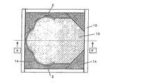
- Each opened body member 2 is preferably fixed in position by a frame member 14.
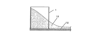
- FIG. 8a is a schematic plan view showing a state after the polyurethane resin composition in the tank is cast into the casting mold.
- FIG. 8b is a schematic cross-sectional view taken along the line A-A 'of FIG. 8a.
- the polyurethane resin composition in the tank can be cast without generating air voids in the casting mold by a simple operation. Can be made.
- the raw material adhering to the inner wall of the tank stays near the inner wall and is difficult to cast, there is an advantage that it is difficult to mix into the entire polyurethane resin composition in the casting mold.
- a polyurethane foam is produced by curing the cast polyurethane resin composition.
- the tank is preferably removed before the polyurethane resin composition is cured.
- heating and post-curing the reacted foam until it no longer flows is preferable because it has the effect of improving the physical properties of the foam.
- the polyurethane foam block in the casting mold is taken out, and the block is sliced to a predetermined thickness using a band saw type or canna type slicer to produce a polishing layer (single layer type polishing pad).
- the thickness of the polyurethane foam block is not particularly limited, but is usually about 50 to 100 mm.
- the thickness of the polishing layer is not particularly limited, but is usually about 0.8 to 4 mm, preferably 1.0 to 2.5 mm.
- the thickness variation of the polishing layer is preferably 100 ⁇ m or less. When the thickness variation exceeds 100 ⁇ m, the polishing layer has a large waviness, and there are portions where the contact state with the material to be polished is different, which adversely affects the polishing characteristics.
- the polishing layer surface is dressed with a dresser in which diamond abrasive grains are electrodeposited and fused at the initial stage of polishing, but the thickness variation exceeds the above range. Since the dressing time becomes longer, the production efficiency decreases.
- a method for suppressing the variation in the thickness of the polishing layer there is a method of buffing the surface of the polishing layer sliced to a predetermined thickness. Moreover, when buffing, it is preferable to carry out stepwise with abrasives having different particle sizes.
- the average cell diameter of the polishing layer is preferably 20 to 80 ⁇ m, more preferably 30 to 60 ⁇ m.
- the Asker D hardness of the polishing layer is preferably 45 to 65 degrees, more preferably 55 to 65 degrees.
- the specific gravity of the polishing layer is preferably 0.6 to 0.87, more preferably 0.75 to 0.85.
- the polishing surface that comes into contact with the material to be polished of the polishing layer preferably has a concavo-convex structure for holding and renewing the slurry.
- the polishing layer made of foam has many openings on the polishing surface and has the function of holding and updating the slurry. By forming a concavo-convex structure on the polishing surface, the slurry can be held and updated more efficiently. It can be performed well, and destruction of the material to be polished due to adsorption with the material to be polished can be prevented.
- the concavo-convex structure is not particularly limited as long as it is a shape that holds and renews the slurry.
- an XY lattice groove for example, an XY lattice groove, a concentric circular groove, a through hole, a non-penetrating hole, a polygonal column, a cylinder, a spiral groove, Examples include eccentric circular grooves, radial grooves, and combinations of these grooves.
- these uneven structures are generally regular, but in order to make the slurry retention and renewability desirable, the groove pitch, groove width, groove depth, etc. should be changed for each range. Is also possible.
- the polishing pad of the present invention may be a laminate of the polishing layer and a cushion sheet.
- the cushion sheet (cushion layer) supplements the characteristics of the polishing layer.
- the cushion sheet is necessary for achieving both planarity and uniformity in a trade-off relationship in CMP.
- Planarity refers to the flatness of a pattern portion when a material having fine irregularities generated during pattern formation is polished, and uniformity refers to the uniformity of the entire material to be polished.
- the planarity is improved by the characteristics of the polishing layer, and the uniformity is improved by the characteristics of the cushion sheet.
- the cushion sheet examples include a fiber nonwoven fabric such as a polyester nonwoven fabric, a nylon nonwoven fabric, and an acrylic nonwoven fabric, a resin-impregnated nonwoven fabric such as a polyester nonwoven fabric impregnated with polyurethane, a polymer resin foam such as polyurethane foam and polyethylene foam, a butadiene rubber, Examples thereof include rubber resins such as isoprene rubber and photosensitive resins.
- a fiber nonwoven fabric such as a polyester nonwoven fabric, a nylon nonwoven fabric, and an acrylic nonwoven fabric
- a resin-impregnated nonwoven fabric such as a polyester nonwoven fabric impregnated with polyurethane
- a polymer resin foam such as polyurethane foam and polyethylene foam
- butadiene rubber examples thereof include rubber resins such as isoprene rubber and photosensitive resins.
- Examples of means for attaching the polishing layer and the cushion sheet include a method of sandwiching and pressing the polishing layer and the cushion sheet with a double-sided tape.
- polishing pad of the present invention may be provided with a double-sided tape on the surface to be bonded to the platen.
- the semiconductor device is manufactured through a process of polishing the surface of the semiconductor wafer using the polishing pad.
- a semiconductor wafer is generally a laminate of a wiring metal and an oxide film on a silicon wafer.
- the semiconductor wafer polishing method and polishing apparatus are not particularly limited, and for example, a polishing surface plate that supports a polishing pad (polishing layer), a support table (polishing head) that supports the semiconductor wafer, and uniform pressure on the wafer are performed.
- a polishing apparatus equipped with a backing material and an abrasive supply mechanism is used.
- the polishing pad is attached to the polishing surface plate by pasting with a double-sided tape.
- the polishing surface plate and the support base are disposed so that the polishing pad and the semiconductor wafer supported by each surface face each other, and each has a rotation shaft. Further, a pressure mechanism for pressing the semiconductor wafer against the polishing pad is provided on the support base side. In polishing, the semiconductor wafer is pressed against the polishing pad while rotating the polishing surface plate and the support base, and polishing is performed while supplying slurry.
- the flow rate of the slurry, the polishing load, the polishing platen rotation speed, and the wafer rotation speed are not particularly limited and are appropriately adjusted.
- a semiconductor device is manufactured by dicing, bonding, packaging, or the like.
- the semiconductor device is used for an arithmetic processing device, a memory, and the like.
- Hardness measurement This was performed according to JIS K6253-1997.
- the produced polyurethane foam was cut into a size of 2 cm ⁇ 2 cm (thickness: arbitrary) and used as a sample for hardness measurement. At the time of measurement, the samples were overlapped to a thickness of 6 mm or more.
- the hardness was measured using a hardness meter (manufactured by Kobunshi Keiki Co., Ltd., Asker D type hardness meter).
- the tank shown in FIG. 1 was installed in a casting mold as shown in FIG.
- 100 parts by weight of the prepolymer and 3 parts by weight of a silicon surfactant (manufactured by Toray Dow Corning Silicon, SH-192) were added and mixed, adjusted to 80 ° C. and degassed under reduced pressure. Then, it stirred vigorously for about 4 minutes so that a bubble might be taken in in a reaction system with the rotation speed of 900 rpm using the stirring blade.
- Etcure 300 manufactured by Albemarle, mixture of 3,5-bis (methylthio) -2,6-toluenediamine and 3,5-bis (methylthio) -2,4-toluenediamine previously adjusted to 70 ° C. ) 21 parts by weight was added and stirred for about 1 minute to prepare a polyurethane resin composition.
- the body members adjacent to each other in the tank were moved in a double-open manner to cast the polyurethane resin composition in the tank into the casting mold.
- the tank was removed, and when the polyurethane resin composition lost its fluidity, it was placed in an oven and post-cured at 100 ° C. for 16 hours to obtain a polyurethane foam block.
- the polyurethane foam block heated to about 80 ° C. was sliced using a slicer (AGW, manufactured by VGW-125), and a polyurethane foam sheet (average cell diameter: 50 ⁇ m, specific gravity: 0.86, hardness: 52 degrees) ) Next, using a buffing machine (Amitech Co., Ltd.), the surface of the sheet was buffed to a thickness of 1.27 mm to obtain a sheet with an adjusted thickness accuracy.
- the buffed sheet is punched out with a diameter of 61 cm, and a concentric circle having a groove width of 0.25 mm, a groove pitch of 1.50 mm, and a groove depth of 0.40 mm on the surface using a groove processing machine (manufactured by Techno).
- Groove processing was performed to obtain a polishing layer.
- a double-sided tape was applied to the surface of the polishing layer opposite to the grooved surface using a laminator. Further, the surface of the corona-treated cushion sheet (manufactured by Toray Industries, Inc., polyethylene foam, Torepef, thickness 0.8 mm) was buffed and bonded to the double-sided tape using a laminator. Further, a double-sided tape was attached to the other surface of the cushion sheet using a laminator to prepare a polishing pad.
- the tank of the present invention is a tank for containing a resin composition, and is used particularly when a polishing pad is produced from a resin composition having a high viscosity or a high thixotropic property.
- the polishing pad of the present invention is made of an optical material such as a lens or a reflection mirror, a silicon wafer, a glass substrate for a hard disk, an aluminum substrate, or a material that requires high surface flatness such as general metal polishing processing. Used for flattening.
- the polishing pad of the present invention is particularly suitable for a step of planarizing a silicon wafer and a device having an oxide layer, a metal layer, etc. formed thereon, before further laminating and forming these oxide layers and metal layers. Used for.
- Tank 2 Body member 3: Connection part 4: Opening / closing member 5: Connection member 6: Handle member 7: Seal member 8: Auxiliary member 9: Seal member 10: Friction resistance reducing member 11: Locking member 12: Casting Mold 13: Polyurethane resin composition 14: Frame member
Landscapes
- Engineering & Computer Science (AREA)
- Mechanical Engineering (AREA)
- Finish Polishing, Edge Sharpening, And Grinding By Specific Grinding Devices (AREA)
- Mechanical Treatment Of Semiconductor (AREA)
Abstract
Description
(平均気泡径)
作製したポリウレタン発泡体を厚み1mm以下になるべく薄くミクロトームカッターで平行に切り出したものを平均気泡径測定用試料とした。試料をスライドガラス上に固定し、SEM(S-3500N、日立サイエンスシステムズ(株))を用いて100倍で観察した。得られた画像を画像解析ソフト(WinRoof、三谷商事(株))を用いて、任意範囲の全気泡径を測定し、平均気泡径を算出した。
JIS Z8807-1976に準拠して行った。作製したポリウレタン発泡体を4cm×8.5cmの短冊状(厚み:任意)に切り出したものを比重測定用試料とし、温度23℃±2℃、湿度50%±5%の環境で16時間静置した。測定には比重計(ザルトリウス社製)を用い、比重を測定した。
JIS K6253-1997に準拠して行った。作製したポリウレタン発泡体を2cm×2cm(厚み:任意)の大きさに切り出したものを硬度測定用試料とし、温度23℃±2℃、湿度50%±5%の環境で16時間静置した。測定時には、試料を重ね合わせ、厚み6mm以上とした。硬度計(高分子計器社製、アスカーD型硬度計)を用い、硬度を測定した。
反応容器にトルエンジイソシアネート(2,4-体/2,6-体=80/20の混合物)1229重量部、4,4’-ジシクロヘキシルメタンジイソシアネート272重量部、数平均分子量1018のポリテトラメチレンエーテルグリコール1901重量部、ジエチレングリコール198重量部を入れ、70℃で4時間反応させてイソシアネート末端プレポリマーを得た。
2:胴体部材
3:連結部
4:開閉部材
5:連結部材
6:把手部材
7:シール部材
8:補助部材
9:シール部材
10:摩擦抵抗低減部材
11:係止部材
12:注型モールド
13:ポリウレタン樹脂組成物
14:枠部材
Claims (6)
- 樹脂組成物を収容するためのタンクにおいて、前記タンクは、2つ以上の胴体部材を連結部を介して枠状に連結することで構成されており、少なくとも1箇所の連結部には、隣り合う胴体部材同士を両開き可能に連結する開閉部材が設けられており、他の少なくとも1箇所の連結部には、隣り合う胴体部材同士を開き戸状に連結する連結部材が設けられていることを特徴とするタンク。
- 前記タンクは円筒状であり、かつ前記胴体部材は3つである請求項1記載のタンク。
- ポリウレタン樹脂からなる研磨層を作製する工程を含む研磨パッドの製造方法において、前記工程は、
注型モールド内に設置した請求項1記載のタンクの中にポリウレタン樹脂組成物を収容する工程(A)、
前記タンクに設けられた開閉部材を開放し、隣り合う胴体部材同士を両開きに移動させることにより、タンク内のポリウレタン樹脂組成物を注型モールド内に流延させる工程(B)、
流延させたポリウレタン樹脂組成物を硬化させることによりポリウレタン樹脂を作製する工程(C)を含む研磨パッドの製造方法。 - 前記工程(A)は、タンク内で、イソシアネート基含有化合物及びシリコン系界面活性剤を含む第1成分を非反応性気体の存在下で撹拌し、非反応性気体を微細気泡として分散させて気泡分散液を調製し、調製した気泡分散液に活性水素基含有化合物を含む第2成分を混合してポリウレタン樹脂組成物を調製して収容する工程である請求項3記載の研磨パッドの製造方法。
- 請求項3記載の製造方法により得られる研磨パッド。
- 請求項5記載の研磨パッドを用いて半導体ウエハの表面を研磨する工程を含む半導体デバイスの製造方法。
Priority Applications (6)
| Application Number | Priority Date | Filing Date | Title |
|---|---|---|---|
| KR20137021854A KR101487212B1 (ko) | 2011-04-25 | 2011-04-25 | 탱크, 상기 탱크를 사용한 연마 패드의 제조 방법 |
| SG2013078530A SG194578A1 (en) | 2011-04-25 | 2011-04-25 | Tank and method for producing polishing pad using tank |
| MYPI2013003815A MY163432A (en) | 2011-04-25 | 2011-04-25 | Tank and method for producing polishing pad using tank |
| CN2011800700728A CN103476566A (zh) | 2011-04-25 | 2011-04-25 | 容器及使用了该容器的研磨垫的制造方法 |
| US14/111,120 US9283649B2 (en) | 2011-04-25 | 2011-04-25 | Tank and method for producing polishing pad using tank |
| PCT/JP2011/060046 WO2012147147A1 (ja) | 2011-04-25 | 2011-04-25 | タンク、該タンクを用いた研磨パッドの製造方法 |
Applications Claiming Priority (1)
| Application Number | Priority Date | Filing Date | Title |
|---|---|---|---|
| PCT/JP2011/060046 WO2012147147A1 (ja) | 2011-04-25 | 2011-04-25 | タンク、該タンクを用いた研磨パッドの製造方法 |
Publications (1)
| Publication Number | Publication Date |
|---|---|
| WO2012147147A1 true WO2012147147A1 (ja) | 2012-11-01 |
Family
ID=47071690
Family Applications (1)
| Application Number | Title | Priority Date | Filing Date |
|---|---|---|---|
| PCT/JP2011/060046 Ceased WO2012147147A1 (ja) | 2011-04-25 | 2011-04-25 | タンク、該タンクを用いた研磨パッドの製造方法 |
Country Status (6)
| Country | Link |
|---|---|
| US (1) | US9283649B2 (ja) |
| KR (1) | KR101487212B1 (ja) |
| CN (1) | CN103476566A (ja) |
| MY (1) | MY163432A (ja) |
| SG (1) | SG194578A1 (ja) |
| WO (1) | WO2012147147A1 (ja) |
Cited By (1)
| Publication number | Priority date | Publication date | Assignee | Title |
|---|---|---|---|---|
| US9745436B2 (en) | 2013-01-15 | 2017-08-29 | Toyo Tire & Rubber Co., Ltd. | Sensor and a method of making the same |
Families Citing this family (4)
| Publication number | Priority date | Publication date | Assignee | Title |
|---|---|---|---|---|
| WO2012147147A1 (ja) * | 2011-04-25 | 2012-11-01 | 東洋ゴム工業株式会社 | タンク、該タンクを用いた研磨パッドの製造方法 |
| USD796279S1 (en) * | 2016-03-16 | 2017-09-05 | Sherrill Barina | Tree trunk shield |
| US11207757B2 (en) * | 2019-06-17 | 2021-12-28 | Skc Solmics Co., Ltd. | Composition for polishing pad, polishing pad and preparation method of semiconductor device |
| US12600562B2 (en) * | 2021-05-12 | 2026-04-14 | Essity Hygiene And Health Aktiebolag | Waste bin arrangement |
Citations (4)
| Publication number | Priority date | Publication date | Assignee | Title |
|---|---|---|---|---|
| JP2002226537A (ja) * | 2001-02-01 | 2002-08-14 | Toyo Tire & Rubber Co Ltd | 研磨パッド用ポリウレタン発泡体の製造装置 |
| JP2004189820A (ja) * | 2002-12-10 | 2004-07-08 | Toyobo Co Ltd | 研磨シート用高分子材料、研磨シート、及び研磨パッド |
| JP2004188716A (ja) * | 2002-12-10 | 2004-07-08 | Toyo Tire & Rubber Co Ltd | 研磨パッドの製造方法、研磨パッド、及び半導体デバイスの製造方法 |
| JP2008137355A (ja) * | 2006-12-05 | 2008-06-19 | Toyo Tire & Rubber Co Ltd | 樹脂成形体の製造装置、樹脂成形体形成用原液の収容タンク及び樹脂成形体の製造方法 |
Family Cites Families (33)
| Publication number | Priority date | Publication date | Assignee | Title |
|---|---|---|---|---|
| US436543A (en) * | 1890-09-16 | Daniel j | ||
| US58648A (en) * | 1866-10-09 | Improvement in the construction of oil-tanks | ||
| US902846A (en) * | 1907-01-28 | 1908-11-03 | James B Smith | Metallic sectional barrel. |
| US931600A (en) * | 1909-03-16 | 1909-08-17 | Alfred C Hafely | Holder or case for phonograph-records and other flat articles. |
| US1169022A (en) * | 1914-11-07 | 1916-01-18 | Joseph D Eldridge | Collapsible barrel. |
| US1276814A (en) * | 1916-11-13 | 1918-08-27 | Weslie March Roades | Tank. |
| US1494818A (en) * | 1918-03-25 | 1924-05-20 | Thomas P Shean | Sectional tank |
| US1430798A (en) * | 1921-08-23 | 1922-10-03 | Leroy Baker Chapman | Tank |
| US1460999A (en) * | 1921-12-13 | 1923-07-03 | Cooper Arthur Spillman | Tank |
| US1972807A (en) * | 1933-08-08 | 1934-09-04 | Hanlon Waters Inc | Bolted tank structure |
| US2656969A (en) * | 1950-07-26 | 1953-10-27 | John D Kvasnok | Frusto-conical container |
| US2690274A (en) * | 1952-11-15 | 1954-09-28 | Gladys M Thurston | Receptacle |
| US2798784A (en) * | 1954-05-26 | 1957-07-09 | Paul W Marshall | Portable pie container |
| US2833087A (en) * | 1956-01-17 | 1958-05-06 | Arthur N Wedding | Knock down metal container |
| NL278162A (ja) * | 1960-08-25 | |||
| DE8211051U1 (de) * | 1982-04-19 | 1982-07-01 | Fritz Schäfer GmbH, 5908 Neunkirchen | Transportabler Vorrats- und/oder Lagerbehaelter fuer Kleinteile oder dergleichen |
| US5054635A (en) * | 1986-10-31 | 1991-10-08 | Alcoa/Tre, Inc. | Rapid assembly and load distribution system for nestable container sections |
| JPH06256Y2 (ja) * | 1988-01-25 | 1994-01-05 | 株式会社カンセイ | 燃料タンク装置 |
| JP2837761B2 (ja) * | 1990-12-06 | 1998-12-16 | 三井化学株式会社 | バッフルプレートを備えた燃料タンクの成形方法 |
| US5514245A (en) | 1992-01-27 | 1996-05-07 | Micron Technology, Inc. | Method for chemical planarization (CMP) of a semiconductor wafer to provide a planar surface free of microscratches |
| JP2789153B2 (ja) | 1992-01-27 | 1998-08-20 | マイクロン テクノロジー インコーポレイテッド | マイクロスクラッチのない平滑面を形成するための半導体ウェハの化学機械的平坦化方法 |
| US6026999A (en) * | 1998-02-20 | 2000-02-22 | Defs Inc. | Concentric tool box for motorized conveyances |
| US6117295A (en) * | 1998-04-15 | 2000-09-12 | Drytronic, Inc. | Method for dehydrating a porous material |
| EP1170271A1 (en) * | 2000-07-06 | 2002-01-09 | Giuseppe Marocco | Methoid for consolidating natural stone blocks |
| US6902061B1 (en) * | 2000-09-29 | 2005-06-07 | Paul Elstone | Collapsible liquid box |
| US6732880B1 (en) * | 2002-09-27 | 2004-05-11 | Franklin Delano Nash, Sr. | Nash trash can 2(NTC2)/trash and storage receptacle |
| US7966786B2 (en) * | 2003-06-26 | 2011-06-28 | Sim-Tech Filters, Inc. | Molded sectioned riser and locking cover |
| US8181806B2 (en) * | 2005-04-25 | 2012-05-22 | Edgar Hidalgo Vargas | Collapsible container |
| US20060283852A1 (en) * | 2005-06-16 | 2006-12-21 | Charles Greiner | Hinged refuse disposal unit |
| US7963397B2 (en) * | 2006-02-09 | 2011-06-21 | Seagle Vance L | Modular, knock-down, light weight, thermally insulating, tamper proof shipping container and fire retardant shipping container bag |
| CN101652090B (zh) * | 2007-09-07 | 2013-07-24 | 勒库埃公司 | 适合于在微波炉内烹调的用于盛放食物的器具 |
| CN201712948U (zh) * | 2010-06-18 | 2011-01-19 | 彭实 | 旋转式定量装置 |
| WO2012147147A1 (ja) * | 2011-04-25 | 2012-11-01 | 東洋ゴム工業株式会社 | タンク、該タンクを用いた研磨パッドの製造方法 |
-
2011
- 2011-04-25 WO PCT/JP2011/060046 patent/WO2012147147A1/ja not_active Ceased
- 2011-04-25 US US14/111,120 patent/US9283649B2/en not_active Expired - Fee Related
- 2011-04-25 SG SG2013078530A patent/SG194578A1/en unknown
- 2011-04-25 MY MYPI2013003815A patent/MY163432A/en unknown
- 2011-04-25 CN CN2011800700728A patent/CN103476566A/zh active Pending
- 2011-04-25 KR KR20137021854A patent/KR101487212B1/ko not_active Expired - Fee Related
Patent Citations (4)
| Publication number | Priority date | Publication date | Assignee | Title |
|---|---|---|---|---|
| JP2002226537A (ja) * | 2001-02-01 | 2002-08-14 | Toyo Tire & Rubber Co Ltd | 研磨パッド用ポリウレタン発泡体の製造装置 |
| JP2004189820A (ja) * | 2002-12-10 | 2004-07-08 | Toyobo Co Ltd | 研磨シート用高分子材料、研磨シート、及び研磨パッド |
| JP2004188716A (ja) * | 2002-12-10 | 2004-07-08 | Toyo Tire & Rubber Co Ltd | 研磨パッドの製造方法、研磨パッド、及び半導体デバイスの製造方法 |
| JP2008137355A (ja) * | 2006-12-05 | 2008-06-19 | Toyo Tire & Rubber Co Ltd | 樹脂成形体の製造装置、樹脂成形体形成用原液の収容タンク及び樹脂成形体の製造方法 |
Cited By (1)
| Publication number | Priority date | Publication date | Assignee | Title |
|---|---|---|---|---|
| US9745436B2 (en) | 2013-01-15 | 2017-08-29 | Toyo Tire & Rubber Co., Ltd. | Sensor and a method of making the same |
Also Published As
| Publication number | Publication date |
|---|---|
| MY163432A (en) | 2017-09-15 |
| KR101487212B1 (ko) | 2015-01-28 |
| US20140038493A1 (en) | 2014-02-06 |
| KR20130117856A (ko) | 2013-10-28 |
| SG194578A1 (en) | 2013-12-30 |
| CN103476566A (zh) | 2013-12-25 |
| US9283649B2 (en) | 2016-03-15 |
Similar Documents
| Publication | Publication Date | Title |
|---|---|---|
| JP5484145B2 (ja) | 研磨パッド | |
| WO2013089240A1 (ja) | 研磨パッド | |
| JP4897238B2 (ja) | 研磨パッド | |
| JP2017132012A (ja) | 研磨パッドの製造方法 | |
| JP5008927B2 (ja) | 研磨パッド | |
| JP2007214151A (ja) | 研磨パッド | |
| US9283649B2 (en) | Tank and method for producing polishing pad using tank | |
| JP4786347B2 (ja) | 研磨パッド | |
| WO2014167900A1 (ja) | 研磨パッドの製造方法 | |
| JP5013447B2 (ja) | 研磨パッド及びその製造方法 | |
| JP4859110B2 (ja) | 研磨パッド | |
| JP4930837B2 (ja) | 研磨パッド | |
| JP6155018B2 (ja) | 研磨パッド | |
| JP4884808B2 (ja) | 研磨パッドの製造方法 | |
| JP2014111296A (ja) | 研磨パッド及びその製造方法 | |
| JP5506008B2 (ja) | 研磨パッド | |
| JP5453148B2 (ja) | タンク、該タンクを用いた研磨パッドの製造方法 | |
| JP4128607B2 (ja) | 研磨パッド | |
| JP2017113856A (ja) | 研磨パッド及びその製造方法 | |
| JP4979200B2 (ja) | 研磨パッド | |
| JP5105461B2 (ja) | 研磨パッド | |
| TWI450811B (zh) | A storage tank and a polishing pad manufacturing method using the same | |
| JP2007007838A (ja) | 研磨パッド及びその製造方法 | |
| JP6155019B2 (ja) | 研磨パッド | |
| JP2013066974A (ja) | 研磨パッド |
Legal Events
| Date | Code | Title | Description |
|---|---|---|---|
| 121 | Ep: the epo has been informed by wipo that ep was designated in this application |
Ref document number: 11864343 Country of ref document: EP Kind code of ref document: A1 |
|
| ENP | Entry into the national phase |
Ref document number: 20137021854 Country of ref document: KR Kind code of ref document: A |
|
| WWE | Wipo information: entry into national phase |
Ref document number: 14111120 Country of ref document: US |
|
| NENP | Non-entry into the national phase |
Ref country code: DE |
|
| 122 | Ep: pct application non-entry in european phase |
Ref document number: 11864343 Country of ref document: EP Kind code of ref document: A1 |
|
| NENP | Non-entry into the national phase |
Ref country code: JP |