WO2012147145A1 - 冷媒圧縮機及びこれを用いた冷凍サイクル装置 - Google Patents
冷媒圧縮機及びこれを用いた冷凍サイクル装置 Download PDFInfo
- Publication number
- WO2012147145A1 WO2012147145A1 PCT/JP2011/060032 JP2011060032W WO2012147145A1 WO 2012147145 A1 WO2012147145 A1 WO 2012147145A1 JP 2011060032 W JP2011060032 W JP 2011060032W WO 2012147145 A1 WO2012147145 A1 WO 2012147145A1
- Authority
- WO
- WIPO (PCT)
- Prior art keywords
- oil
- amount
- refrigerant
- oil supply
- refrigerant compressor
- Prior art date
- Legal status (The legal status is an assumption and is not a legal conclusion. Google has not performed a legal analysis and makes no representation as to the accuracy of the status listed.)
- Ceased
Links
Images


Classifications
-
- F—MECHANICAL ENGINEERING; LIGHTING; HEATING; WEAPONS; BLASTING
- F04—POSITIVE - DISPLACEMENT MACHINES FOR LIQUIDS; PUMPS FOR LIQUIDS OR ELASTIC FLUIDS
- F04C—ROTARY-PISTON, OR OSCILLATING-PISTON, POSITIVE-DISPLACEMENT MACHINES FOR LIQUIDS; ROTARY-PISTON, OR OSCILLATING-PISTON, POSITIVE-DISPLACEMENT PUMPS
- F04C29/00—Component parts, details or accessories of pumps or pumping installations, not provided for in groups F04C18/00 - F04C28/00
- F04C29/02—Lubrication; Lubricant separation
- F04C29/021—Control systems for the circulation of the lubricant
-
- F—MECHANICAL ENGINEERING; LIGHTING; HEATING; WEAPONS; BLASTING
- F04—POSITIVE - DISPLACEMENT MACHINES FOR LIQUIDS; PUMPS FOR LIQUIDS OR ELASTIC FLUIDS
- F04B—POSITIVE-DISPLACEMENT MACHINES FOR LIQUIDS; PUMPS
- F04B39/00—Component parts, details, or accessories, of pumps or pumping systems specially adapted for elastic fluids, not otherwise provided for in, or of interest apart from, groups F04B25/00 - F04B37/00
- F04B39/02—Lubrication
- F04B39/0207—Lubrication with lubrication control systems
-
- F—MECHANICAL ENGINEERING; LIGHTING; HEATING; WEAPONS; BLASTING
- F04—POSITIVE - DISPLACEMENT MACHINES FOR LIQUIDS; PUMPS FOR LIQUIDS OR ELASTIC FLUIDS
- F04B—POSITIVE-DISPLACEMENT MACHINES FOR LIQUIDS; PUMPS
- F04B39/00—Component parts, details, or accessories, of pumps or pumping systems specially adapted for elastic fluids, not otherwise provided for in, or of interest apart from, groups F04B25/00 - F04B37/00
- F04B39/02—Lubrication
- F04B39/0223—Lubrication characterised by the compressor type
- F04B39/023—Hermetic compressors
- F04B39/0261—Hermetic compressors with an auxiliary oil pump
-
- F—MECHANICAL ENGINEERING; LIGHTING; HEATING; WEAPONS; BLASTING
- F04—POSITIVE - DISPLACEMENT MACHINES FOR LIQUIDS; PUMPS FOR LIQUIDS OR ELASTIC FLUIDS
- F04C—ROTARY-PISTON, OR OSCILLATING-PISTON, POSITIVE-DISPLACEMENT MACHINES FOR LIQUIDS; ROTARY-PISTON, OR OSCILLATING-PISTON, POSITIVE-DISPLACEMENT PUMPS
- F04C15/00—Component parts, details or accessories of machines, pumps or pumping installations, not provided for in groups F04C2/00 - F04C14/00
- F04C15/0088—Lubrication
- F04C15/0092—Control systems for the circulation of the lubricant
-
- F—MECHANICAL ENGINEERING; LIGHTING; HEATING; WEAPONS; BLASTING
- F04—POSITIVE - DISPLACEMENT MACHINES FOR LIQUIDS; PUMPS FOR LIQUIDS OR ELASTIC FLUIDS
- F04C—ROTARY-PISTON, OR OSCILLATING-PISTON, POSITIVE-DISPLACEMENT MACHINES FOR LIQUIDS; ROTARY-PISTON, OR OSCILLATING-PISTON, POSITIVE-DISPLACEMENT PUMPS
- F04C18/00—Rotary-piston pumps specially adapted for elastic fluids
- F04C18/02—Rotary-piston pumps specially adapted for elastic fluids of arcuate-engagement type, i.e. with circular translatory movement of co-operating members, each member having the same number of teeth or tooth-equivalents
- F04C18/0207—Rotary-piston pumps specially adapted for elastic fluids of arcuate-engagement type, i.e. with circular translatory movement of co-operating members, each member having the same number of teeth or tooth-equivalents both members having co-operating elements in spiral form
- F04C18/0215—Rotary-piston pumps specially adapted for elastic fluids of arcuate-engagement type, i.e. with circular translatory movement of co-operating members, each member having the same number of teeth or tooth-equivalents both members having co-operating elements in spiral form where only one member is moving
-
- F—MECHANICAL ENGINEERING; LIGHTING; HEATING; WEAPONS; BLASTING
- F04—POSITIVE - DISPLACEMENT MACHINES FOR LIQUIDS; PUMPS FOR LIQUIDS OR ELASTIC FLUIDS
- F04C—ROTARY-PISTON, OR OSCILLATING-PISTON, POSITIVE-DISPLACEMENT MACHINES FOR LIQUIDS; ROTARY-PISTON, OR OSCILLATING-PISTON, POSITIVE-DISPLACEMENT PUMPS
- F04C23/00—Combinations of two or more pumps, each being of rotary-piston or oscillating-piston type, specially adapted for elastic fluids; Pumping installations specially adapted for elastic fluids; Multi-stage pumps specially adapted for elastic fluids
- F04C23/008—Hermetic pumps
-
- F—MECHANICAL ENGINEERING; LIGHTING; HEATING; WEAPONS; BLASTING
- F04—POSITIVE - DISPLACEMENT MACHINES FOR LIQUIDS; PUMPS FOR LIQUIDS OR ELASTIC FLUIDS
- F04C—ROTARY-PISTON, OR OSCILLATING-PISTON, POSITIVE-DISPLACEMENT MACHINES FOR LIQUIDS; ROTARY-PISTON, OR OSCILLATING-PISTON, POSITIVE-DISPLACEMENT PUMPS
- F04C28/00—Control of, monitoring of, or safety arrangements for, pumps or pumping installations specially adapted for elastic fluids
- F04C28/08—Control of, monitoring of, or safety arrangements for, pumps or pumping installations specially adapted for elastic fluids characterised by varying the rotational speed
-
- F—MECHANICAL ENGINEERING; LIGHTING; HEATING; WEAPONS; BLASTING
- F04—POSITIVE - DISPLACEMENT MACHINES FOR LIQUIDS; PUMPS FOR LIQUIDS OR ELASTIC FLUIDS
- F04C—ROTARY-PISTON, OR OSCILLATING-PISTON, POSITIVE-DISPLACEMENT MACHINES FOR LIQUIDS; ROTARY-PISTON, OR OSCILLATING-PISTON, POSITIVE-DISPLACEMENT PUMPS
- F04C29/00—Component parts, details or accessories of pumps or pumping installations, not provided for in groups F04C18/00 - F04C28/00
- F04C29/02—Lubrication; Lubricant separation
- F04C29/028—Means for improving or restricting lubricant flow
-
- F—MECHANICAL ENGINEERING; LIGHTING; HEATING; WEAPONS; BLASTING
- F25—REFRIGERATION OR COOLING; COMBINED HEATING AND REFRIGERATION SYSTEMS; HEAT PUMP SYSTEMS; MANUFACTURE OR STORAGE OF ICE; LIQUEFACTION SOLIDIFICATION OF GASES
- F25B—REFRIGERATION MACHINES, PLANTS OR SYSTEMS; COMBINED HEATING AND REFRIGERATION SYSTEMS; HEAT PUMP SYSTEMS
- F25B31/00—Compressor arrangements
- F25B31/002—Lubrication
- F25B31/004—Lubrication oil recirculating arrangements
-
- F—MECHANICAL ENGINEERING; LIGHTING; HEATING; WEAPONS; BLASTING
- F25—REFRIGERATION OR COOLING; COMBINED HEATING AND REFRIGERATION SYSTEMS; HEAT PUMP SYSTEMS; MANUFACTURE OR STORAGE OF ICE; LIQUEFACTION SOLIDIFICATION OF GASES
- F25B—REFRIGERATION MACHINES, PLANTS OR SYSTEMS; COMBINED HEATING AND REFRIGERATION SYSTEMS; HEAT PUMP SYSTEMS
- F25B49/00—Arrangement or mounting of control or safety devices
- F25B49/02—Arrangement or mounting of control or safety devices for compression type machines, plants or systems
- F25B49/022—Compressor control arrangements
-
- F—MECHANICAL ENGINEERING; LIGHTING; HEATING; WEAPONS; BLASTING
- F04—POSITIVE - DISPLACEMENT MACHINES FOR LIQUIDS; PUMPS FOR LIQUIDS OR ELASTIC FLUIDS
- F04B—POSITIVE-DISPLACEMENT MACHINES FOR LIQUIDS; PUMPS
- F04B2203/00—Motor parameters
- F04B2203/02—Motor parameters of rotating electric motors
- F04B2203/0209—Rotational speed
-
- F—MECHANICAL ENGINEERING; LIGHTING; HEATING; WEAPONS; BLASTING
- F04—POSITIVE - DISPLACEMENT MACHINES FOR LIQUIDS; PUMPS FOR LIQUIDS OR ELASTIC FLUIDS
- F04C—ROTARY-PISTON, OR OSCILLATING-PISTON, POSITIVE-DISPLACEMENT MACHINES FOR LIQUIDS; ROTARY-PISTON, OR OSCILLATING-PISTON, POSITIVE-DISPLACEMENT PUMPS
- F04C2240/00—Components
- F04C2240/80—Other components
- F04C2240/806—Pipes for fluids; Fittings therefor
-
- F—MECHANICAL ENGINEERING; LIGHTING; HEATING; WEAPONS; BLASTING
- F04—POSITIVE - DISPLACEMENT MACHINES FOR LIQUIDS; PUMPS FOR LIQUIDS OR ELASTIC FLUIDS
- F04C—ROTARY-PISTON, OR OSCILLATING-PISTON, POSITIVE-DISPLACEMENT MACHINES FOR LIQUIDS; ROTARY-PISTON, OR OSCILLATING-PISTON, POSITIVE-DISPLACEMENT PUMPS
- F04C2270/00—Control; Monitoring or safety arrangements
- F04C2270/05—Speed
- F04C2270/052—Speed angular
-
- F—MECHANICAL ENGINEERING; LIGHTING; HEATING; WEAPONS; BLASTING
- F04—POSITIVE - DISPLACEMENT MACHINES FOR LIQUIDS; PUMPS FOR LIQUIDS OR ELASTIC FLUIDS
- F04C—ROTARY-PISTON, OR OSCILLATING-PISTON, POSITIVE-DISPLACEMENT MACHINES FOR LIQUIDS; ROTARY-PISTON, OR OSCILLATING-PISTON, POSITIVE-DISPLACEMENT PUMPS
- F04C29/00—Component parts, details or accessories of pumps or pumping installations, not provided for in groups F04C18/00 - F04C28/00
- F04C29/04—Heating; Cooling; Heat insulation
-
- F—MECHANICAL ENGINEERING; LIGHTING; HEATING; WEAPONS; BLASTING
- F25—REFRIGERATION OR COOLING; COMBINED HEATING AND REFRIGERATION SYSTEMS; HEAT PUMP SYSTEMS; MANUFACTURE OR STORAGE OF ICE; LIQUEFACTION SOLIDIFICATION OF GASES
- F25B—REFRIGERATION MACHINES, PLANTS OR SYSTEMS; COMBINED HEATING AND REFRIGERATION SYSTEMS; HEAT PUMP SYSTEMS
- F25B13/00—Compression machines, plants or systems, with reversible cycle
-
- F—MECHANICAL ENGINEERING; LIGHTING; HEATING; WEAPONS; BLASTING
- F25—REFRIGERATION OR COOLING; COMBINED HEATING AND REFRIGERATION SYSTEMS; HEAT PUMP SYSTEMS; MANUFACTURE OR STORAGE OF ICE; LIQUEFACTION SOLIDIFICATION OF GASES
- F25B—REFRIGERATION MACHINES, PLANTS OR SYSTEMS; COMBINED HEATING AND REFRIGERATION SYSTEMS; HEAT PUMP SYSTEMS
- F25B2600/00—Control issues
- F25B2600/02—Compressor control
- F25B2600/021—Inverters therefor
-
- F—MECHANICAL ENGINEERING; LIGHTING; HEATING; WEAPONS; BLASTING
- F25—REFRIGERATION OR COOLING; COMBINED HEATING AND REFRIGERATION SYSTEMS; HEAT PUMP SYSTEMS; MANUFACTURE OR STORAGE OF ICE; LIQUEFACTION SOLIDIFICATION OF GASES
- F25B—REFRIGERATION MACHINES, PLANTS OR SYSTEMS; COMBINED HEATING AND REFRIGERATION SYSTEMS; HEAT PUMP SYSTEMS
- F25B2700/00—Sensing or detecting of parameters; Sensors therefor
- F25B2700/17—Speeds
- F25B2700/171—Speeds of the compressor
-
- F—MECHANICAL ENGINEERING; LIGHTING; HEATING; WEAPONS; BLASTING
- F25—REFRIGERATION OR COOLING; COMBINED HEATING AND REFRIGERATION SYSTEMS; HEAT PUMP SYSTEMS; MANUFACTURE OR STORAGE OF ICE; LIQUEFACTION SOLIDIFICATION OF GASES
- F25B—REFRIGERATION MACHINES, PLANTS OR SYSTEMS; COMBINED HEATING AND REFRIGERATION SYSTEMS; HEAT PUMP SYSTEMS
- F25B2700/00—Sensing or detecting of parameters; Sensors therefor
- F25B2700/19—Pressures
- F25B2700/193—Pressures of the compressor
- F25B2700/1931—Discharge pressures
-
- F—MECHANICAL ENGINEERING; LIGHTING; HEATING; WEAPONS; BLASTING
- F25—REFRIGERATION OR COOLING; COMBINED HEATING AND REFRIGERATION SYSTEMS; HEAT PUMP SYSTEMS; MANUFACTURE OR STORAGE OF ICE; LIQUEFACTION SOLIDIFICATION OF GASES
- F25B—REFRIGERATION MACHINES, PLANTS OR SYSTEMS; COMBINED HEATING AND REFRIGERATION SYSTEMS; HEAT PUMP SYSTEMS
- F25B2700/00—Sensing or detecting of parameters; Sensors therefor
- F25B2700/19—Pressures
- F25B2700/193—Pressures of the compressor
- F25B2700/1933—Suction pressures
-
- Y—GENERAL TAGGING OF NEW TECHNOLOGICAL DEVELOPMENTS; GENERAL TAGGING OF CROSS-SECTIONAL TECHNOLOGIES SPANNING OVER SEVERAL SECTIONS OF THE IPC; TECHNICAL SUBJECTS COVERED BY FORMER USPC CROSS-REFERENCE ART COLLECTIONS [XRACs] AND DIGESTS
- Y02—TECHNOLOGIES OR APPLICATIONS FOR MITIGATION OR ADAPTATION AGAINST CLIMATE CHANGE
- Y02B—CLIMATE CHANGE MITIGATION TECHNOLOGIES RELATED TO BUILDINGS, e.g. HOUSING, HOUSE APPLIANCES OR RELATED END-USER APPLICATIONS
- Y02B30/00—Energy efficient heating, ventilation or air conditioning [HVAC]
- Y02B30/70—Efficient control or regulation technologies, e.g. for control of refrigerant flow, motor or heating
Definitions
- the present invention relates to a refrigerant compressor such as a rotary compressor or a scroll compressor used in room air conditioners, package air conditioners, heat pump water heaters, etc., and a refrigeration cycle apparatus using the same, and in particular, an eco (environmental response) effect.
- a refrigerant compressor such as a rotary compressor or a scroll compressor used in room air conditioners, package air conditioners, heat pump water heaters, etc.
- a refrigeration cycle apparatus using the same, and in particular, an eco (environmental response) effect.
- Wide-range operation at motor system drive signal frequency that is suitable as a refrigerant compressor for refrigeration and air conditioning circuits in air conditioning and hot water supply systems for high-generation homes and that uses a new refrigerant with a low global warming potential (GWP) Particularly for those operating in the very low speed mode of operation.
- GWP global warming potential
- a valve for opening and closing the oil supply path is provided in the middle of the oil supply path, and the pressure difference between the high pressure part and the low pressure part opens and closes the valve, thereby reducing the oil supply path. It is also known to change to a stage and to adjust the amount of refueling by this.
- one refrigerant compressor that is used in air conditioners and water heaters is required to be able to control the capacity in a wide range with one unit, and in particular, it is possible to operate with a very small capacity at low heat load. It is required.
- the cooling operation of the air conditioner it is generally necessary that the temperature of the room is high at the start of the operation, and therefore, the operation needs to be performed rapidly.
- a large capacity and high speed operation (high speed rotation) is performed at the time of start, but when the room is cooled to some extent and shifted from the start to a steady operation state, a low capacity low speed operation (low speed rotation) is performed.
- This low-speed operation in the steady-state operation state is a very low rotational speed (ultra-low speed, especially when it is used in an air conditioner installed in a building equipped with high insulation materials, in which recent energy saving has been implemented. Driving will be performed in the driving mode).
- a valve for opening and closing the oil supply path is provided, and the valve is changed by the pressure difference between the high pressure part and the low pressure part, thereby changing the throttle in the oil supply path in two stages Under the conditions, the amount of oil supply is suppressed to prevent the decrease in volumetric efficiency due to suction heating due to the excessive amount of oil supply at high load.
- the oil separated from the discharged refrigerant gas in the oil separator connected to the discharge side of the compressor is flow-controlled according to the operating conditions to supply oil to the compression mechanism part. ing.
- the purpose is to prevent the temperature rise of the compressor. That is, in the case of Patent Document 3, the temperature of the discharged refrigerant gas is lowered by lowering the temperature of the oil supplied to the compression mechanism using an oil cooler and adjusting the flow rate of the supplied oil according to the temperature of the discharged refrigerant gas. We are trying to prevent the rise.
- the oil valve is controlled in the closing direction so that the high temperature oil from the oil separator is not directly supplied to the compressor suction side, and the oil is circulated in the cycle. It is intended to prevent the temperature rise of the discharged refrigerant gas by returning the low temperature oil.
- Patent Documents 3 and 4 have the effect of reducing the heating loss, they do not take into consideration the loss due to the refrigerant leakage in the compression chamber at the time of the low rotational speed which is a low load condition. It is impossible to improve the efficiency at the time.
- the object of the present invention is to reduce the refrigerant leakage in the compression chamber and the refrigerant heating loss due to oil in a wide operation range from high speed rotation to a very low rotation speed (super low speed operation mode), thereby achieving efficient operation
- An object of the present invention is to obtain a possible refrigerant compressor and a refrigeration cycle apparatus using the same.
- the present invention provides a sealed case, a compression mechanism portion housed in the sealed case, and an electric motor portion housed in the sealed case and driving the compression mechanism portion via a crankshaft.
- a refrigerant compressor including an oil reservoir formed at a lower portion of the sealed case, wherein the oil reservoir in the sealed case and the suction side of the compression mechanism communicate with each other, and the oil in the oil reservoir is suctioned.
- the fuel amount control unit controls the fuel amount adjustment unit according to the rotation speed detected by the rotation speed detection unit, and the fuel supply amount control unit is configured to control the fuel supply pipe from the fuel supply pipe as the rotation speed of the motor unit increases. Oil amount to be supplied to the serial suction side and controls the fuel supply amount adjusting means so as to decrease.
- Another feature of the present invention is a sealed case, a compression mechanism unit housed in the sealed case, a motor unit housed in the sealed case and for driving the compression mechanism unit via a crankshaft.
- An oil reservoir formed at a lower portion of the sealed case, and the compression mechanism portion includes a fixed scroll on which a spiral wrap is provided upright on a base plate, and a spiral wrap provided on a mirror plate.
- a plurality of compression chambers are formed by meshing engagement with the orbiting scroll, and a back pressure chamber held at an intermediate pressure between the discharge pressure and the suction pressure is provided on the back surface of the orbiting scroll.
- the oil reservoir in the closed case and the back pressure chamber are communicated with each other, and the oil of the oil reservoir is used as the back A refueling pipe for leading to a chamber, refueling amount adjustment means for adjusting the refueling amount provided on the refueling pipe and supplied to the back pressure chamber, rotation number detection means for detecting the number of rotations of the motor unit
- the fuel amount control unit controls the fuel amount adjustment unit according to the rotation speed detected by the rotation speed detection unit, and the oil supply control unit controls the fuel supply as the rotation speed of the motor unit increases.
- An object of the present invention is to control the oil amount adjustment means so that the amount of oil supplied from the pipe to the suction pipe is reduced.
- Still another feature of the present invention is a refrigeration cycle apparatus in which a refrigeration cycle is configured by connecting a refrigerant compressor, an outdoor heat exchanger, an expansion valve, and an indoor heat exchanger with a refrigerant pipe
- the refrigerant compressor comprising: Is provided with an outdoor temperature sensor for detecting the temperature of the outdoor heat exchanger and an indoor temperature sensor for detecting the temperature of the indoor heat exchanger using the refrigerant compressor, and the refrigerant compressor is provided with
- the refueling amount control unit is controlled to decrease the refueling amount as the rotation speed of the motor unit increases, and the temperature difference between the condensation temperature and the evaporation temperature detected by the outdoor temperature sensor and the indoor temperature sensor increases. Control to further reduce the amount of refueling according to
- efficient operation is achieved by reducing refrigerant leakage in the compression chamber and refrigerant heating loss due to oil in a wide operation range from high speed rotation to very low rotation speed (ultra low speed operation mode).
- a possible refrigerant compressor and a refrigeration cycle apparatus using the same can be obtained.
- FIG. 7 is a diagram for explaining the relationship between the compressor rotational speed and the target oil supply amount according to the first embodiment of the present invention.
- the control flowchart which demonstrates the amount control of oil supply in Example 1 of this invention.
- the longitudinal cross-sectional view of the refrigerant compressor which shows Example 2 of this invention.
- FIG. 7 is a diagram for explaining the relationship between the compressor rotational speed and the target oil supply amount in Embodiment 2 of the present invention.
- FIG. 1 is a longitudinal sectional view of a refrigerant compressor showing a first embodiment of the present invention, which is an embodiment in which the present invention is applied to a scroll compressor.
- a scroll compressor (compressor) 1 as a refrigerant compressor shown in FIG. 1 is a disc-shaped base plate, a wrap erected spirally on the base plate, and an outer peripheral side of the base plate.
- a fixed scroll 7 having a cylindrical support portion having an end plate surface continuous with the tip end face of the wrap and surrounding the wrap; a disc-like end plate; a spiral wrap provided upright on the end plate;
- the orbiting scroll 8 is provided with a boss portion provided at the center of the rear surface of the end plate.
- the orbiting scroll 8 is disposed to face the fixed scroll 7, and the wrap of the orbiting scroll is rotatably provided within the frame 17 in mesh with the wrap of the stationary scroll.
- An outer peripheral portion (support portion) of the fixed scroll 7 is fixed to the frame 17 by a bolt or the like, and the frame 17 integrated with the fixed scroll 7 is fixed to the sealing case 9 by fixing means such as welding.
- the outer peripheral side of the orbiting scroll 8 is an end plate surface that slides on the outer peripheral side of the fixed scroll 7, and the surface of the fixed scroll 7 that slides on the end plate surface of the orbiting scroll is an end plate surface of the fixed scroll 7. ing.
- a compression mechanism (scrolling portion) 2 configured by the fixed scroll 7 and the orbiting scroll 8 or the like, and a motor portion 16 for driving the compression mechanism 2 via the crankshaft 10.
- It has a sealed container structure in which a main bearing 5 and a sub bearing 23 for rotatably supporting the crankshaft 10 and the like are accommodated, and an oil reservoir 53 for storing lubricating oil is further provided at the lower portion of the sealed case 9. ing.
- the crankshaft 10 is integrally fixed to a rotor of the motor unit 16 and coaxial with a central axis of the fixed scroll 7.
- a crank portion 10 a is provided at the tip end of the crankshaft 10, and the crank portion 10 a is inserted into the orbiting bearing 11 provided in the boss portion 34 of the orbiting scroll 8, and the orbiting scroll 8 is of the crankshaft 10. It is configured to be capable of pivotal movement with rotation.
- the central axis of the orbiting scroll 8 is eccentric by a predetermined distance with respect to the central axis of the fixed scroll 7, and the wrap of the orbiting scroll 8 is overlapped with the wrap of the fixed scroll 7 by a predetermined angle in the circumferential direction. ing.
- the orbiting scroll 8 is configured to pivot relative to the fixed scroll 7 by the Oldham ring 12 while being restrained so as not to rotate on its axis.
- a suction pipe 14 is provided so as to penetrate through the sealed case 9 and communicate with the suction chamber 20 on the outer peripheral side of the fixed scroll 7, and 15 communicates with the compression chamber 13 on the innermost peripheral side of the fixed scroll 7.
- the discharge port is formed in the vicinity of the spiral center of the fixed scroll base plate.
- the crankshaft 10 When the crankshaft 10 is rotationally driven by the motor unit 16, the crankshaft 10 is transmitted to the orbiting scroll 8 via the crank portion 10 a of the crankshaft 10 and the orbiting bearing 11, and the orbiting scroll 8 is predetermined about the central axis of the stationary scroll 7. It moves with the turning radius.
- the compression chambers 13 formed between the wraps continuously move to the center side of the fixed scroll 7, and the volume of the compression chamber 13 is continuously reduced along with the movement.
- the fluid for example, refrigerant gas circulating the refrigeration cycle
- the fluid discharged into the discharge space 24 is a motor in which the motor unit 16 is accommodated via a passage (not shown) formed between the outer periphery of the fixed scroll 7 and the frame 17 and the inner surface of the sealed case 9. It flows into the chamber 25, oil (lubricant oil, refrigeration oil) is separated, and is supplied from the discharge pipe 6 to the outside of the compressor, for example, to a refrigeration cycle.
- oil lubricant oil, refrigeration oil
- the oil separated from the refrigerant gas is stored in an oil reservoir 53 at the bottom of the closed case 9.
- the oil of the oil reservoir 53 is supplied again to a sliding portion such as a bearing by a volumetric or centrifugal oil supply pump 21 provided at the lower end of the crankshaft 10. That is, with the rotation of the crankshaft 10, the oil supply pump 21 is also rotated, and the oil in the oil reservoir 53 is sucked from the lubricating oil suction port provided in the oil supply pump case 22 and discharged from the discharge port of the oil supply pump 21. Ru.
- the discharged oil is supplied upward through a through hole 3 formed to penetrate axially in the crankshaft 10.
- a portion of the oil passing through the through hole 3 passes through a lateral hole formed in the crankshaft 10 and is supplied to the auxiliary bearing 23 to lubricate the auxiliary bearing, and the oil reservoir 53 at the bottom of the sealed case 9 Return.
- Most other oil passing through the through hole 3 reaches the upper end of the crank shaft 10 through the through hole 3 and lubricates the pivot bearing 11 through an oil groove 57 provided on the outer periphery of the crank portion.
- the oil that has flowed out of the orbiting bearing 11 thereafter lubricates the main bearing 5 provided at the lower portion of the orbiting bearing 11, and then returns to the oil reservoir 53 through the oil drainage pipe 26.
- the first space is a space having a pressure close to the discharge pressure.
- the seal member 32 is accommodated in an annular groove 31 formed in the frame 17 together with a wave spring (not shown), and the first space 33 serving as a discharge pressure, the suction pressure and the discharge pressure It is separated from the back pressure chamber (second space) 18 which has an intermediate pressure.
- the oil leakage means 30 is composed of a plurality of holes provided on the lower end surface of the turning boss 34, and the plurality of holes perform a circular motion across the seal member 32 along with the turning motion of the turning scroll 8. And move between the first space 33 and the back pressure chamber (second space) 18.
- the lubricating oil in the first space 33 is stored in the hole (oil leakage means) 30 and intermittently transferred to the back pressure chamber 18 side, thereby guiding the minimum necessary oil to the back pressure chamber 18 It is like that.
- a slit or the like may be provided as the oil leakage means 30 to the back pressure chamber 18.
- the oil that has entered the back pressure chamber 18 flows into the compression chamber 13 through the back pressure hole 35 communicating the back pressure chamber 18 with the compression chamber 13. That is, when the back pressure (the pressure in the back pressure chamber 18) becomes higher than the pressure in the compression chamber 13 in communication with the back pressure hole 35, the oil in the back pressure chamber 18 enters the compression chamber 13 due to the pressure difference. Flow.
- the oil flowing into the compression chamber 13 lubricates the sliding surfaces of the fixed scroll 7 and the orbiting scroll 8 and is then discharged from the discharge port 15 together with the refrigerant gas.
- Most of the oil in the discharge space 24 and the motor chamber 25 is the refrigerant It is separated from the gas and stored in the oil reservoir 53. The remaining oil is discharged from the discharge pipe 6 to the refrigeration cycle together with the refrigerant gas.
- the necessary amount of oil can be supplied to each bearing portion, and the Oldham ring 12 and the fixed scroll 7 are provided.
- the sliding portion of the orbiting scroll 8 is lubricated, and the amount of oil finally discharged from the compression chamber 13 together with the refrigerant gas can be adjusted independently by the oil leakage means 30. Therefore, in the present embodiment, the amount of oil leaking from the oil leakage means 30 to the back pressure chamber 18 is minimized, and the necessary oil supply amount to the compression chamber, that is, the sliding surface of the lap is the oil amount adjusting means 61 described later.
- the oil supply pipe 53 communicating the suction pipe 14 with the oil reservoir 53 at the bottom of the sealed case 9 where the lubricating oil is stored is provided.
- a refueling amount adjustment means 61 is provided in the middle of the refueling pipe 62.
- the oil supply amount adjusting means 61 is configured by a solenoid valve, and the solenoid valve 61 is configured to be turned on / off (opened / closed) by pulse width adjustment control (hereinafter also referred to as PWM control).
- the solenoid valve 61 when the solenoid valve 61 is turned on (opened), the high pressure oil reservoir 53 and the low pressure suction pipe 14 communicate with each other via the oil supply pipe 62, and the oil in the oil reservoir 53 is on the suction pipe 14 side (suction side) Supplied to Further, when the solenoid valve 61 is turned off (closed), the communication between the oil reservoir 53 and the suction pipe 14 is shut off, and the oil supply is stopped.
- the PWM control of the solenoid valve 61 in the refueling amount control unit 80 has a cycle T1 of the falling section of the rectangular wave in the pulse width adjustment control signal from the solenoid drive circuit provided in the refueling amount control unit 80, and a rising section In the cycle T2, the closed state and the open state are switched to perform flow control. That is, since the flow rate control is performed by changing the ratio of the cycles T1 and T2, the minute flow rate can be easily controlled as compared with the case of controlling the flow rate by adjusting the throttling amount like a needle valve Since the area can be increased, the problem of obstruction due to foreign matter can also be avoided.
- the oil supply amount control unit 80 determines the cycle T1 and the cycle T2 of the rectangular wave of the pulse width adjustment control signal according to the rotation speed detected by the rotation speed detection means of the compressor. .
- the pulse width adjustment control signal from the solenoid drive circuit according to a table set in advance so that the amount of fuel supplied to the suction pipe 14 side of the refrigerant compressor becomes the target flow rate in the range of 0 to 60 cc / min.
- the cycles T1 and T2 are determined.
- the relationship between the oil supply amount Q and the cycles T1 and T2 in the pulse width adjustment control signal is the flow coefficient of the solenoid valve 61, the coefficient C1 determined by the flow path resistance of the pipe, etc., the coefficient C2 related to the duty ratio and the flow, and the pressure difference ⁇ P. Basically, it can be expressed by the following equation.
- the target flow rate is changed according to the number of revolutions of the compressor, and the oil supply amount is controlled to be in the range of 0 to 60 cc / min.
- the relationship between the amount and the compressor rotational speed is shown in FIG.
- the target oil supply amount in the present embodiment is Q1 (for example, 55 cc / min) when the number of revolutions of the compressor is the minimum number of revolutions, and 0 cc / min
- the amount of oil supply is reduced as the compressor rotational speed increases.
- the ratio of the periods T1 and T2 of the pulse width adjustment control signal may be changed.
- the compressor rotation number detection means is configured to detect a signal of the target rotation number in the compressor drive circuit 71 by being input to the fuel supply amount control device 80.
- the oil amount control is performed on the compressor target rotation speed, the oil supply amount Q1 is obtained at the minimum rotation speed, and the oil supply amount is decreased according to the increase in the rotation speed so that the oil supply amount is 0 at the rotation speed N1. Control.
- step S1 the target rotational speed N of the compressor is read (step S1).
- step S2 since the coefficients C2 and Q1 and N1 are known numerical values as shown in FIG. 2, the duty ratio “T2 / (T1 + T2) is obtained according to the current target rotational speed N read in step S1. ] Can be asked.
- the calculated periods T1 and T2 are output from the solenoid drive circuit of the oil supply amount control unit 80 to the solenoid valve 61 as a pulse width adjustment control signal (step S3).
- steps S1 to S3 each time the compressor rotational speed changes, the amount of oil supplied from the oil reservoir 53 to the suction pipe 14 can be controlled according to the compressor rotational speed. .
- the flow adjustment is performed by switching the open state and the closed state of the solenoid valve 61, and the ratio between the close time (period T1) and the open time (period T2) of the solenoid valve 61 is changed.
- Refueling amount can be varied from 0 to 100%.
- the refrigerant compressor according to the first embodiment of the present invention described above from the operation mode with high capacity and high speed rotation to the ultra low speed operation mode with operation at a very low rotation speed (for example, about 5 to 20 Hz)
- a very low rotation speed for example, about 5 to 20 Hz
- FIG. 4 is a longitudinal sectional view showing a scroll compressor as a refrigerant compressor of the present embodiment.
- the portions given the same reference numerals as those in FIG. 1 indicate the same or corresponding portions, and therefore the description of the same portions will be omitted.
- the second embodiment differs from the first embodiment in that the oil supply pipe 62 is provided so as to connect the oil reservoir 53 and the back pressure chamber 18, and in the middle of the oil supply pipe 62.
- a refueling amount adjusting means (solenoid valve) 61 is provided as in the first embodiment.
- the solenoid valve is pulse width adjustment control (PWM control) and turned on (opened), the high pressure oil reservoir 53 and the back pressure chamber 18 having an intermediate pressure between high and low pressure
- the oil supply pipe 62 connecting them is in communication, and the oil in the oil reservoir 53 is supplied to the back pressure chamber 18.
- the solenoid valve 61 is turned off (closed)
- the communication of the oil supply pipe is interrupted in the previous period, and the oil supply is stopped.
- the oil that has entered the back pressure chamber 18 flows into the compression chamber 13 via the back pressure hole 35 communicating the back pressure chamber 18 with the compression chamber 13 when the back pressure becomes high.
- the oil leakage means configured of the plurality of holes 30 provided in the turning boss portion 34 and the seal member 32 is provided, but in the case of the present embodiment, the oil Leakage means are not necessary. That is, the oil whose flow rate is controlled by the oil supply amount adjusting means (solenoid valve) 61 and supplied to the back pressure chamber 18 lubricates the Oldham ring 12 and the sliding portion of the fixed scroll 7 and the orbiting scroll 8. It is for being supplied to the compression chamber.
- the amount of oil supplied to the Oldham ring 12 and the amount of oil supplied to the sliding portions of the fixed scroll 7 and the orbiting scroll 8 can not be controlled independently. For this reason, it is preferable to use a member having appropriate wear resistance for the sliding portion of the Oldham ring 12 and the fixed scroll 7 and the orbiting scroll 8, and even when the amount of oil supplied to the compression chamber 13 is narrowed, It is good to be able to secure sufficient reliability.
- the amount of oil supplied via the oil amount adjustment means 61 is equal to the amount of oil supplied to the Oldham ring 12 and the amount of oil supplied to the sliding portions of the fixed scroll 7 and the orbiting scroll 8. Because the flow rate is increased, flow control can be performed more easily.
- the oil supply amount control unit 80 determines the periods T1 and T2 of the rectangular wave of the pulse width adjustment control signal according to the rotation speed of the compressor.
- the pulse width adjustment control signal output from the solenoid drive circuit of the oil supply amount control unit 80 according to a table set in advance so that the oil supply amount has the oil supply characteristic as shown in FIG. Determine the periods T1 and T2 in.
- the basic equation of the relationship between the oil supply amount Q and the periods T1 and T2 in the pulse width adjustment control signal is the same as the above-mentioned equation 1.
- the target oil supply amount in this embodiment is Q1 (for example, 80 cc / min) when the rotation speed of the compressor is the minimum rotation speed, and Q2 (for example, 45 cc / min) when the rotation speed N1 (for example 45 Hz) It controls so that the amount of refueling decreases as the number of rotations of a compressor becomes large. Further, when the rotational speed is N1 or more, the ratio of the periods T1 and T2 is changed so that the amount of fueling is constant at Q2.
- the compressor rotational speed is detected by inputting a signal of the target rotational speed in the compressor drive circuit 71 to the oil supply amount control unit 80.
- step S3 A control flow chart of this refueling amount control is shown in FIG.
- the target rotational speed N of the compressor is read (step S1).
- step S4 it is compared whether or not the read target rotational speed N is the rotational speed N1 or more shown in FIG. 5, and when N is N1 (45 Hz in FIG. 5) or more, the process moves to step S5.
- the duty ratio “T2 / (T1 + T2)” is determined so as to be the minimum oil supply amount Q2 (45 cc / min in FIG. 5).
- the calculated periods T1 and T2 are output from the solenoid drive circuit of the oil supply control unit 80 to the solenoid valve 61 as a pulse width adjustment control signal (step S3).
- step S4 If the read target rotational speed N is smaller than the rotational speed N1 shown in FIG. 5 in step S4, the process proceeds to step S6, and the amount of oil supply (this amount of oil is shown in FIG. 5) according to the formula shown in step S6.
- the duty ratio "T2 / (T1 + T2)" is obtained so as to obtain the obtained amount of oil supply.
- the calculated periods T1 and T2 are output from the solenoid drive circuit of the oil supply control unit 80 to the solenoid valve 61 as a pulse width adjustment control signal (step S3).
- FIG. 7 shows the room air conditioner as the refrigeration cycle apparatus (air conditioner) 100 using the refrigerant compressor of the first embodiment.
- the refrigerant compressed by the compressor 101 flows from the high pressure side connection pipe 107 into the four-way valve 105, flows out to the outdoor connection pipe 108, and is outdoor heat exchanger 102.
- the outdoor heat exchanger 102 the high-temperature and high-pressure refrigerant gas is condensed and liquefied by heat exchange with outdoor air, and after passing through the liquid receiver 106, the pressure is reduced by the expansion valve 103.
- the depressurized low temperature and low pressure refrigerant flows into the indoor heat exchanger 104 to exchange heat with the indoor air, cools the indoor air, and evaporates and gasifies by depriving the indoor air of its own heat.
- the refrigerant gas flows into the four-way valve 105 from the indoor connection pipe 109, flows out from the low pressure side connection port of the four-way valve, passes through the low pressure side connection pipe 110, and returns to the suction side of the compressor 101 again. It is compressed again, and the same cycle is repeated thereafter.
- the connection destination of the refrigerant pipe of the four-way valve 105 is switched, and the high temperature / high pressure refrigerant gas discharged from the compressor 101 flows from the high pressure side connection pipe 107 into the four-way valve 10, It flows out to the indoor connection pipe 109 and flows to the indoor heat exchanger 104. Then, the heating operation can be performed by radiating the heat of the refrigerant gas to the indoor air.
- the refrigerant gas is condensed in the indoor heat exchanger 104 and depressurized by the expansion valve 103, and the refrigerant which has become low temperature and low pressure exchanges heat with the outdoor air in the outdoor heat exchanger 102 for evaporation and gasification, and the outdoor connection piping 108 After flowing into the four-way valve 105, the refrigerant flows out to the low pressure side connection pipe 110 and is again sucked into the compressor 101, thereby repeating the refrigeration cycle.
- An oil supply pipe 62 communicates, as shown in FIG. 1, an oil reservoir 53 at the bottom of the compressor with a low pressure side pipe 110 on the suction side of the compression mechanism 2.
- a refueling amount adjusting means (solenoid valve) 61 is provided in the middle of the refueling pipe 62. By controlling the oil supply amount adjusting means 61, the amount of oil supplied from the oil reservoir 53 to the low pressure side connection pipe 110 is adjusted.
- the oil amount adjustment means 61 controls the closed state and the open state of the valve according to the pulse width adjustment control signal output from the oil amount control unit 80 so that the oil amount can be varied from 0 to 100%. It has become.
- a temperature sensor (not shown) is provided in the vicinity of the air passage inlet of the indoor heat exchanger 104 installed in the room, thereby detecting the room temperature and matching the target temperature set by the user
- control is performed by varying the number of rotations of the compressor 101 by the inverter device (compressor drive circuit) 71.
- the oil supply amount control unit 80 reads the compressor target rotation number from the inverter device 71, determines the periods T1 and T2 of the rectangular wave of the pulse width adjustment control signal according to it, and outputs it to the oil supply amount adjustment means 61. .
- FIG. 8 The refrigeration cycle apparatus shown in FIG. 8 is also used for a room air conditioner, and the basic operation of the refrigeration cycle is the same as that of FIG. 7 described above.
- the fuel amount adjustment means (solenoid valve) 61 is pulse width adjusted and controlled by the fuel amount control unit 80.
- the oil supply amount control unit 80 reads the target rotation speed of the compressor from the inverter device 71.
- the discharge pipe 6 is provided with the discharge pressure detection means 72
- the suction pipe 14 is provided with the suction pressure detection means 73 (both are shown in FIG. 1). Pressure is also detected.
- the cycles T1 and T2 of the rectangular wave of the pulse width adjustment control signal are determined according to the target rotation speed and the detected discharge pressure and suction pressure, and are output to the oil supply amount adjustment means 61.
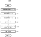
- a control flow chart of the refueling amount in the fourth embodiment is shown in FIG.
- the amount of oil passing through the solenoid valve (oil supply amount adjusting means) 61 depends not only on the ratio between the time of the closed state (period T1) and the time of the open state (period T2) in the solenoid valve but also on the pressure difference ⁇ P. Do.
- the pressure difference dP is calculated from the discharge pressure Pd and the suction pressure Ps (steps S7 and S8) detected by the discharge pressure detection means 72 and the suction pressure detection means 73 (step S9).
- the cycles T1 and T2 are corrected based on the calculated pressure difference dP so that the amount of oil supply becomes optimal (step S10).
- the calculated periods T1 and T2 are output from the solenoid drive circuit of the oil supply control unit 80 to the solenoid valve 61 as a pulse width adjustment control signal (step S3).
- step S3 a pulse width adjustment control signal
- the steps S1, S7 to S10 and S3 each time the compressor rotational speed changes, the amount of oil supplied from the oil reservoir 53 to the suction pipe 14 is controlled according to the compressor rotational speed. can do.
- step S4 it is compared whether or not the read target rotational speed N is the rotational speed N1 or more shown in FIG. 5, and when N is N1 or more, the process proceeds to step S11, and the pressure difference dP obtained in step S9.
- the duty ratio "T2 / (T1 + T2)" is determined so that the minimum amount of fueling "Q2 / (C1 ⁇ dP)" taking into account the above is obtained.
- the calculated periods T1 and T2 are output from the solenoid drive circuit of the oil supply control unit 80 to the solenoid valve 61 as a pulse width adjustment control signal (step S3).
- step S4 when the read target rotational speed N is smaller than the rotational speed N1, the process proceeds to step S12, and the calculation formula shown in the step S12, that is, according to the rotational speed N and the pressure difference dP.
- the amount of refueling is determined by the equation for determining the duty ratio, and the duty ratio “T2 / (T1 + T2)” is determined so as to obtain the determined amount of refueling. Note that a 0 , a 1 , and a 2 in the calculation formula of step S12 are coefficients obtained in advance.
- step S3 the process proceeds to step S3, and the calculated periods T1 and T2 are output from the solenoid drive circuit of the oil supply amount control unit 80 to the solenoid valve 61 as a pulse width adjustment control signal.
- the oil reservoir 53 is operated according to the compressor rotational speed and the pressure difference.
- the amount of oil supplied to the back pressure chamber 18 can be controlled.
- FIG. 11 is a schematic block diagram of a refrigeration cycle apparatus using a refrigerant compressor showing a fifth embodiment of the present invention, which is an example applied to a room air conditioner as a refrigeration cycle apparatus.
- the parts in FIG. 11 to which the same reference numerals as in FIG. 11 are identical to the same reference numerals as in FIG.
- the fuel amount adjustment means (solenoid valve) 61 is pulse width adjusted and controlled by the fuel amount control unit 80.
- the oil supply amount control unit 80 obtains a signal of the target rotation speed N of the compressor from the inverter device (compressor drive circuit) 71, and the temperature sensor 74 and the outdoor heat exchanger 102 provided in the indoor heat exchanger 104.
- the evaporation temperature and the condensation temperature are detected by the temperature sensor 75 provided, and the periods T1 and T2 of the rectangular wave of the pulse width adjustment control signal are determined according to the detected evaporation temperature and the condensation temperature, and the oiling amount It outputs to the adjustment means 61.
- a control flow chart of the refueling amount in the present embodiment is shown in FIG.
- the amount of oil passing through the solenoid valve (oiling amount adjusting means) 61 depends not only on the ratio between the time of the closed state (period T1) and the time of the open state (period T2) of the solenoid valve but also on the pressure difference ⁇ P. Do. Therefore, in the present embodiment, the pressure difference ⁇ P is estimated from the evaporation temperature and the condensation temperature detected by the temperature sensor 74 provided in the indoor heat exchanger 104 and the temperature sensor 75 provided in the outdoor heat exchanger 102. Then, the periods T1 and T2 are corrected so as to optimize the amount of oil supply. According to this embodiment, without using the pressure detecting means (pressure sensors) 72 and 73 as described in the fourth embodiment, it is possible to appropriately perform the adjustment of the amount of fueling under the operating condition where the operating pressure is different, The same effect as in Example 4 can be obtained.
- the control flowchart shown in FIG. 12 differs from the control flowchart shown in FIG. 9 in steps S13 to S16. That is, the evaporation temperature Ts and the condensation temperature Td detected by the temperature sensors 74 and 75 are read (steps S13 and S14), their temperature difference dT is determined (step S15), and fueling is performed based on the obtained temperature difference dT. The periods T1 and T2 are corrected so as to optimize the amount (step S16). Others are similar to the control shown in FIG. Also in the present embodiment, similarly to the above-described fourth embodiment, the amount of oil supply can be appropriately adjusted even under the operating conditions where the rotation speed is the same but the operating pressure is different.
- the control flow chart is for the case of using the refrigerant compressor of the first embodiment as the refrigerant compressor, but the control flow chart of the amount of oil supply when the refrigerant compressor of the second embodiment is used is as shown in FIG. Become.
- steps S1, S13 to S15, and S3 are the same as those shown in FIG. Steps in which the example shown in FIG. 13 differs from the example shown in FIG. 12 are steps S4, S17 and S18.
- step S4 it is compared whether or not the read target rotational speed N is the rotational speed N1 or more shown in FIG. 5, and when N is N1 or more, the process proceeds to step S17 and the temperature difference dT determined in step S15.
- the duty ratio "T2 / (T1 + T2)" is determined so that the minimum amount of fueling "Q2 / (C1.dT)" taking into account the above is obtained.
- the calculated periods T1 and T2 are output from the solenoid drive circuit of the oil supply control unit 80 to the solenoid valve 61 as a pulse width adjustment control signal (step S3).
- step S4 when the read target rotational speed N is smaller than the rotational speed N1, the process proceeds to step S18, and the calculation formula shown in the step S18, that is, according to the rotational speed N and the temperature difference dT.
- the amount of refueling is determined by the equation for determining the duty ratio, and the duty ratio “T2 / (T1 + T2)” is determined so as to obtain the determined amount of refueling.
- b 0 , b 1 , and b 2 in the calculation formula of step S18 are coefficients obtained in advance.
- step S3 the process proceeds to step S3, and the calculated periods T1 and T2 are output from the solenoid drive circuit of the oil supply amount control unit 80 to the solenoid valve 61 as a pulse width adjustment control signal.
- the oil reservoir 53 is operated according to the compressor rotational speed and the temperature difference.
- the amount of oil supplied to the back pressure chamber 18 can be controlled.
- FIG. 14 is a schematic configuration diagram of a refrigeration cycle apparatus using a refrigerant compressor showing Embodiment 6 of the present invention.
- This example is also an example applied to a room air conditioner as a refrigeration cycle apparatus, and the portions given the same reference numerals in FIG. 14 as those in FIG. 7 are the same or corresponding portions, and therefore redundant description will be omitted.
- the oil supply pipe 62 provided with the oil amount adjustment means 61 in the middle connects the oil reservoir at the lower part of the compressor 101 and the low pressure side connection pipe 110, but the oil amount adjustment means A refrigerant / oil heat exchanger (oil cooling means) 111 is provided between the oil reservoir 61 and the oil reservoir at the lower part of the compressor 101.
- the oil flowing from the oil reservoir 53 to the low pressure side connection pipe 110 in the lower portion of the compressor (bottom portion of the sealed case 9) passes through the refrigerant / oil heat exchanger 111 by opening the oil amount adjustment means 61.
- heat is exchanged with the low pressure side refrigerant which is approximately at the evaporation temperature.
- the temperature of the oil supplied to the low pressure side connection pipe 110 is lowered to increase the viscosity.
- a solenoid valve may be used as the refueling amount adjusting means 61 as in the embodiment described above.
- the flow rate of the oil may be adjusted by the method of the embodiment 1 or 2 described above, but since the oil becomes highly viscous by the effect of the refrigerant / oil heat exchanger 111, the coefficients C1 and C2 have different values.
- the solenoid valve not the solenoid valve but the electric needle valve is adopted as the oil amount adjustment means 61.
- the opening degree of the electric needle valve is controlled by the pulse number modulation control signal output from the oil supply amount control unit 80, and the oil supply amount can be varied from 0 to 100%.
- the coefficient (corresponding to the above-mentioned coefficient C2) determined by the flow coefficient of the valve and the flow passage resistance of the pipe (corresponding to the above-mentioned coefficient C2) becomes smaller as the viscosity of the oil becomes higher.
- the opening degree of the valve can be made large. Therefore, the control of the minute flow rate becomes easy, and the flow path can be made large, so that the needle valve can be used while avoiding the problem of the obstruction due to the foreign matter.
- the electric needle valve capable of continuously changing the opening degree since the electric needle valve capable of continuously changing the opening degree is used, there is no generation of noise accompanying opening and closing of a valve such as a solenoid valve, and the noise can be reduced.
- the fuel amount adjustment unit 61 is pulse number modulation controlled by the fuel amount control unit 80.
- the number of pulses of the pulse number adjustment control signal from the pulse drive circuit is determined according to a table set in advance so that the fuel supply amount becomes a target flow rate of 0 to 60 cc / min.
- the fueling amount control unit 80 obtains information on the target rotation number N of the compressor from the inverter device (compressor driving circuit) 71, determines the number of pulses according to the target rotation number, and is driven by the stepping motor
- the electric needle valve (fuel supply amount adjusting means) 61 outputs.
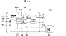
- FIG. 15 is a schematic configuration diagram of a refrigeration cycle apparatus using a refrigerant compressor showing a seventh embodiment of the present invention, and this example is also applied to a room air conditioner as a refrigeration cycle apparatus.
- Parts in FIG. 15 that are assigned the same reference numerals as in FIG. 14 are the same or corresponding parts, and therefore redundant descriptions will be omitted.
- the embodiment shown in FIG. 15 is different from the embodiment shown in FIG. 14 in that the refrigerant / oil heat exchanger 111 in FIG. 14 is omitted and the outdoor heat exchanger 102 has the function of the refrigerant / oil heat exchanger. It is That is, although the oil supply pipe 62 in which the oil supply amount adjusting means (electric needle valve) 61 is disposed in the middle connects the oil reservoir at the lower part of the compressor 101 and the low pressure side connection pipe 110, this oil supply pipe 62 Of the outdoor heat exchanger 102 by passing the piping between the oil supply amount adjusting means 61 and the oil reservoir portion at the lower part of the compressor 101 through the outdoor heat exchanger 102, the refrigerant / oil heat exchanger It is used as (oil cooling means).
- the oil flowing from the oil reservoir 53 at the lower part of the compressor to the low pressure side connection pipe 110 is allowed to flow through the outdoor heat exchanger 102 by opening the oil amount adjustment means 61.
- the heat exchange can be performed with the low pressure side refrigerant which is almost at the evaporation temperature. Therefore, the temperature of the oil supplied to the low pressure side connection pipe 110 can be lowered as in the sixth embodiment, and the viscosity can be increased.
- the refrigerant / oil heat exchanger is integrally provided as a part of the outdoor heat exchanger 102, the refrigerant / oil heat exchanger is provided in the narrow outdoor unit of the room air conditioner (refrigerating cycle device). It is not necessary to arrange separately from the outdoor heat exchanger 102. Therefore, the mounting is facilitated and the cost can be reduced.
- each embodiment of the present invention in the compression chamber in all rotational speed regions from the large capacity and high speed rotation operation mode to the very low rotation speed ultra low speed operation mode.
- Optimal refueling can be achieved that can achieve both refrigerant leakage reduction and reduced heating losses as the oil heats the refrigerant. Therefore, it is possible to obtain a refrigerant compressor with high efficiency and a refrigeration cycle apparatus using the same according to any load capacity.
- this embodiment can realize highly efficient operation when operating at a very low rotational speed in a room air conditioner installed in a highly insulated house.
Landscapes
- Engineering & Computer Science (AREA)
- Mechanical Engineering (AREA)
- General Engineering & Computer Science (AREA)
- Physics & Mathematics (AREA)
- Thermal Sciences (AREA)
- Applications Or Details Of Rotary Compressors (AREA)
- Rotary Pumps (AREA)
- Control Of Positive-Displacement Pumps (AREA)
- Compressor (AREA)
Abstract
Description
=C2・T2/(T1+T2) …(数1)
本実施例においては、前述したように、圧縮機の回転数に応じて、目標流量を変化させ、また前記給油量は0~60cc/minの範囲となるように制御されるが、この目標給油量と圧縮機回転数との関係を図2に示す。本実施例での目標給油量は、直線Aで示すように、圧縮機の回転数が最小回転数の時にはQ1(例えば55cc/min)となり、回転数N1(例えば100Hz)で0cc/minとなるように、圧縮機回転数が大きくなるに従い、給油量を減少させるようにしている。前記直線Aに沿って、給油量を変化させるには、前記パルス幅調整制御信号の前記周期T1とT2との比を変化させれば良い。
ソレノイド弁61の制御を開始すると、まず圧縮機の目標回転数Nを読み込む(ステップS1)。次に、ステップS2では、係数C2、及びQ1とN1は、図2に示すように既知の数値であるので、ステップS1で読み込んだ現在の目標回転数Nにより、デューティ比『T2/(T1+T2)』を求めることができる。この求められた周期T1とT2を、給油量制御部80のソレノイド駆動回路から、パルス幅調整制御信号として前記ソレノイド弁61に出力する(ステップS3)。以下、例えば圧縮機回転数が変化する毎に、前記ステップS1~S3を繰り返すことで、圧縮機回転数に応じて、油溜り部53から吸込パイプ14に供給する油量を制御することができる。
図4は本実施例の冷媒圧縮機としてのスクロール圧縮機を示す縦断面図である。図4において上記図1と同一符号を付した部分は同一或いは相当する部分を示しているので重複する部分についてはその説明を省略する。この実施例2が上記実施例1と異なる点は、給油パイプ62が、油溜り部53と背圧室18とを連通するように設けられている点であり、前記給油パイプ62の途中には、実施例1と同様に、給油量調整手段(ソレノイド弁)61が設けられている。
ソレノイド弁61の制御を開始すると、まず圧縮機の目標回転数Nを読み込む(ステップS1)。次に、ステップS4では、読み込まれた目標回転数Nが図5に示す回転数N1以上か否かを比較し、前記NがN1(図5では45Hz)以上の場合にはステップS5に移り、図5に示す本実施例での給油特性の線Bに示すように、最小の給油量Q2(図5では45cc/min)となるように、デューティ比『T2/(T1+T2)』を求める。この求められた周期T1とT2を、給油量制御部80のソレノイド駆動回路から、パルス幅調整制御信号としてソレノイド弁61に出力する(ステップS3)。
図8に示す冷凍サイクル装置もルームエアコンに用いたものであり、冷凍サイクルの基本動作は上記した図7の場合と同じであり、同一部分には同一符号を付してその説明を省略する。
本実施例においても上記実施例4と同様に、回転数が同じでも運転圧力が異なる運転条件の場合でも、給油量を適切に調整できる。
3:貫通孔、5:主軸受、6:吐出パイプ、
7:固定スクロール、8:旋回スクロール、
9:密閉ケース、10:クランク軸、11:旋回軸受、
12:オルダムリング、13:圧縮室、14:吸込みパイプ、15:吐出ポート、
16:電動機部、17:フレーム、18:背圧室(第2の空間)、
20:吸込室、21:給油ポンプ、22:給油ポンプケース、
23:副軸受、24:吐出空間、25:電動機室、26:排油パイプ、
30:油漏出手段(穴)、31:円環溝、32:シール部材、33:第1の空間、
34:旋回ボス部、35:背圧孔、
53:油溜り部、56:フレームシール(軸受押え)、57:油溝、
61:給油量調整手段(ソレノイド弁、電動ニードル弁)、62:給油パイプ、
71:圧縮機駆動回路(インバータ装置)、
72:吐出圧力検出手段、73:吸込圧力検出手段、
74:室内温度センサ、75:室外温度センサ、
80:給油量制御部、
100:冷凍サイクル装置(空調装置)、
102:室外熱交換器、103:膨張弁、104:室内熱交換器、105:四方弁、
106:受液器、107:高圧側接続配管、108:室外接続配管、
109:室内接続配管、110:低圧側接続配管、
111:冷媒/油熱交換器(油冷却手段)。
Claims (10)
- 密閉ケース、該密閉ケース内に収納された圧縮機構部、前記密閉ケース内に収納されると共に前記圧縮機構部をクランク軸を介して駆動するための電動機部、及び前記密閉ケースの下部に形成された油溜り部を備える冷媒圧縮機において、
前記密閉ケース内の油溜り部と前記圧縮機構部の吸込側を連通し、前記油溜り部の油を前記吸込側に導くための給油パイプと、
この給油パイプに設けられ前記吸込側に供給する給油量を調整するための給油量調整手段と、
前記電動機部の回転数を検出する回転数検出手段と、
前記回転数検出手段により検出された回転数に応じて前記給油量調整手段を制御する給油量制御部を備え、
前記給油量制御部は、前記電動機部の回転数が増加するに従い、前記給油パイプから前記吸込側に供給される給油量が減少するように前記給油量調整手段を制御する
ことを特徴とする冷媒圧縮機。 - 請求項1に記載の冷媒圧縮機において、
前記冷媒圧縮機の吐出側の圧力を検出する吐出圧力検出手段と、前記冷媒圧縮機の吸込側の圧力を検出する吸込圧力検出手段とを備え、
前記給油量制御部は、前記電動機部の回転数が増加するに従い、前記給油パイプから前記吸込側に供給される給油量が減少するように制御すると共に、前記吐出圧力検出手段で検出された吐出圧力と、前記吸込圧力検出手段で検出された吸込圧力との圧力差が増加するに従い前記給油量を更に減少させるように前記給油量調整手段を制御することを特徴とする冷媒圧縮機。 - 請求項2に記載の冷媒圧縮機において、前記密閉ケースを貫通し前記圧縮機構部の吸込室に冷媒を導くための吸込パイプと、前記密閉ケース内に連通して密閉ケース内の高圧の冷媒を密閉ケース外に導く吐出パイプを備え、前記吸込パイプには前記吸込圧力検出手段が設けられ、前記吐出パイプには前記吐出圧力検出手段が設けられていることを特徴とする冷媒圧縮機。
- 請求項1に記載の冷媒圧縮機において、前記給油量調整手段はソレノイド弁であり、前記給油量制御部には前記ソレノイド弁の開閉制御をするためのパルス幅調整制御信号を生成するソレノイド駆動回路を備えていることを特徴とする冷媒圧縮機。
- 密閉ケース、該密閉ケース内に収納された圧縮機構部、前記密閉ケース内に収納されると共に前記圧縮機構部をクランク軸を介して駆動するための電動機部、及び前記密閉ケースの下部に形成された油溜り部とを備え、
前記圧縮機構部は、台板に渦巻状のラップが立設された固定スクロールと、鏡板上に渦巻状のラップが立設された旋回スクロールとが、互いに噛み合わされることで複数の圧縮室が形成され、前記旋回スクロールの背面には吐出圧力と吸込圧力の中間圧力に保持される背圧室が設けられて、前記旋回スクロールは前記中間圧力により前記固定スクロール側に押し付けられるように構成されている冷媒圧縮機において、
前記密閉ケース内の油溜り部と前記背圧室とを連通し、前記油溜り部の油を前記背圧室に導くための給油パイプと、
この給油パイプに設けられ前記背圧室側に供給する給油量を調整するための給油量調整手段と、
前記電動機部の回転数を検出する回転数検出手段と、
前記回転数検出手段により検出された回転数に応じて前記給油量調整手段を制御する給油量制御部を備え、
前記給油量制御部は、前記電動機部の回転数が増加するに従い、前記給油パイプから吸込パイプに供給される給油量が減少するように前記給油量調整手段を制御する
ことを特徴とする冷媒圧縮機。 - 冷媒圧縮機、室外熱交換器、膨張弁、及び室内熱交換器を冷媒配管で接続して冷凍サイクルを構成している冷凍サイクル装置において、
前記冷媒圧縮機には請求項1に記載の冷媒圧縮機を用い、
更に、前記室外熱交換器の温度を検出する室外温度センサと、前記室内熱交換器の温度を検出する室内温度センサを設け、
前記冷媒圧縮機に設けられている給油量制御部は、電動機部の回転数が増加するに従い給油量が減少するよう制御されると共に、前記室外温度センサ及び室内温度センサにより検出された凝縮温度と蒸発温度との温度差が増加するに従い前記給油量を更に減少するよう制御する
ことを特徴とする冷媒圧縮機を用いた冷凍サイクル装置。 - 請求項6に記載の冷凍サイクル装置において、前記冷媒圧縮機の油溜り部と圧縮機構部の吸込側とを接続している前記給油パイプの途中に、該給油パイプを流れる油を冷却するための油冷却手段が設けられていることを特徴とする冷媒圧縮機を用いた冷凍サイクル装置。
- 請求項7に記載の冷凍サイクル装置において、前記油冷却手段は、前記冷媒圧縮機の吸込側に接続されている低圧側配管を流れる低温・低圧の冷媒と、前記給油パイプを流れる高温・高圧の油とを熱交換させる冷媒/油熱交換器であることを特徴とする冷媒圧縮機を用いた冷凍サイクル装置。
- 請求項7に記載の冷凍サイクル装置において、前記油冷却手段は、前記給油パイプにおける給油量調整手段と油溜り部との間の配管を前記室外熱交換器に通すことで、該室外熱交換器の一部を冷媒/油熱交換器として利用するようにして構成されていることを特徴とする冷媒圧縮機を用いた冷凍サイクル装置。
- 請求項7に記載の冷凍サイクル装置において、前記給油パイプに設けられている給油量調整手段は電動ニードル弁であることを特徴とする冷媒圧縮機を用いた冷凍サイクル装置。
Priority Applications (6)
| Application Number | Priority Date | Filing Date | Title |
|---|---|---|---|
| ES11864553.0T ES2613678T3 (es) | 2011-04-25 | 2011-04-25 | Compresor de refrigerante y aparato de ciclo de refrigeración que usa el mismo |
| EP11864553.0A EP2703649B1 (en) | 2011-04-25 | 2011-04-25 | Refrigerant compressor and refrigeration cycle apparatus using same |
| CN201180070389.1A CN103492719B (zh) | 2011-04-25 | 2011-04-25 | 冷媒压缩机以及使用其的冷冻循环装置 |
| JP2013511805A JP5695187B2 (ja) | 2011-04-25 | 2011-04-25 | 冷媒圧縮機及びこれを用いた冷凍サイクル装置 |
| PCT/JP2011/060032 WO2012147145A1 (ja) | 2011-04-25 | 2011-04-25 | 冷媒圧縮機及びこれを用いた冷凍サイクル装置 |
| US14/110,613 US9470230B2 (en) | 2011-04-25 | 2011-04-25 | Refrigerant compressor and refrigeration cycle apparatus using the same |
Applications Claiming Priority (1)
| Application Number | Priority Date | Filing Date | Title |
|---|---|---|---|
| PCT/JP2011/060032 WO2012147145A1 (ja) | 2011-04-25 | 2011-04-25 | 冷媒圧縮機及びこれを用いた冷凍サイクル装置 |
Publications (1)
| Publication Number | Publication Date |
|---|---|
| WO2012147145A1 true WO2012147145A1 (ja) | 2012-11-01 |
Family
ID=47071688
Family Applications (1)
| Application Number | Title | Priority Date | Filing Date |
|---|---|---|---|
| PCT/JP2011/060032 Ceased WO2012147145A1 (ja) | 2011-04-25 | 2011-04-25 | 冷媒圧縮機及びこれを用いた冷凍サイクル装置 |
Country Status (6)
| Country | Link |
|---|---|
| US (1) | US9470230B2 (ja) |
| EP (1) | EP2703649B1 (ja) |
| JP (1) | JP5695187B2 (ja) |
| CN (1) | CN103492719B (ja) |
| ES (1) | ES2613678T3 (ja) |
| WO (1) | WO2012147145A1 (ja) |
Cited By (6)
| Publication number | Priority date | Publication date | Assignee | Title |
|---|---|---|---|---|
| WO2015198647A1 (ja) * | 2014-06-25 | 2015-12-30 | 株式会社日立産機システム | 気体圧縮機 |
| DE112017003912T5 (de) | 2016-08-04 | 2019-05-09 | Sanden Holdings Corporation | Spiralverdichter |
| JP2019167910A (ja) * | 2018-03-26 | 2019-10-03 | 東芝キヤリア株式会社 | 冷凍サイクル装置 |
| CN114110844A (zh) * | 2021-11-22 | 2022-03-01 | 青岛海尔空调电子有限公司 | 压缩机系统、压缩机系统的控制方法及空调器 |
| JP2023059309A (ja) * | 2021-10-15 | 2023-04-27 | 住友金属鉱山株式会社 | スラリーの流量制御装置、流量制御方法、および粗硫酸ニッケル水溶液の脱鉄設備、脱鉄方法 |
| CN116294328A (zh) * | 2023-02-23 | 2023-06-23 | 青岛海尔空调电子有限公司 | 用于冷水机组的控制方法、装置、冷水机组 |
Families Citing this family (23)
| Publication number | Priority date | Publication date | Assignee | Title |
|---|---|---|---|---|
| ITMI20130583A1 (it) * | 2013-04-11 | 2014-10-12 | Frascold S P A | Compressore per un impianto frigorifero e impianto frigorifero comprendente detto compressore |
| KR102310647B1 (ko) | 2014-12-12 | 2021-10-12 | 삼성전자주식회사 | 압축기 |
| KR20160081431A (ko) * | 2014-12-31 | 2016-07-08 | 삼성전자주식회사 | 스크롤 압축기 및 이를 구비한 공기조화장치 |
| US10641268B2 (en) * | 2015-08-11 | 2020-05-05 | Emerson Climate Technologies, Inc. | Multiple compressor configuration with oil-balancing system |
| JP2017096145A (ja) * | 2015-11-20 | 2017-06-01 | 三菱重工業株式会社 | スクロール圧縮機 |
| CN106122029A (zh) * | 2016-08-26 | 2016-11-16 | 成都黄金地真空技术开发有限公司 | 全封闭立式涡旋压缩机喷油冷却系统 |
| US10473377B2 (en) | 2016-09-26 | 2019-11-12 | Carrier Corporation | High outdoor ambient and high suction pressure oil pump out mitigation for air conditioners |
| CN107747544B (zh) * | 2017-11-07 | 2019-07-09 | 苏州英华特涡旋技术有限公司 | 一种带均油管的压缩机、并联式压缩机组及均油方法 |
| DE102018103610B3 (de) * | 2018-02-19 | 2019-02-14 | Hanon Systems | Vorrichtung zum Dämpfen von Druckpulsationen für einen Verdichter eines gasförmigen Fluids |
| US11421681B2 (en) * | 2018-04-19 | 2022-08-23 | Emerson Climate Technologies, Inc. | Multiple-compressor system with suction valve and method of controlling suction valve |
| JP6696533B2 (ja) * | 2018-06-22 | 2020-05-20 | ダイキン工業株式会社 | 冷凍装置 |
| JP7389319B2 (ja) * | 2019-07-29 | 2023-11-30 | ダイキン工業株式会社 | 圧縮機 |
| CN112524035B (zh) * | 2019-09-18 | 2023-03-28 | 上海海立电器有限公司 | 一种压缩机及空调系统 |
| US11655820B2 (en) * | 2020-02-04 | 2023-05-23 | Aspen Compressor, Llc | Horizontal rotary compressor with enhanced tiltability during operation |
| ES3045407T3 (en) * | 2020-07-01 | 2025-11-28 | Daikin Ind Ltd | Heat source unit and scroll compressor |
| KR102864623B1 (ko) * | 2020-09-25 | 2025-09-26 | 엘지전자 주식회사 | 스크롤 압축기 |
| US11892211B2 (en) | 2021-05-23 | 2024-02-06 | Copeland Lp | Compressor flow restrictor |
| JP7830084B2 (ja) * | 2021-11-22 | 2026-03-16 | 三菱重工サーマルシステムズ株式会社 | 圧縮機 |
| JP2023162674A (ja) * | 2022-04-27 | 2023-11-09 | ダイキン工業株式会社 | 圧縮機における冷媒としての使用、圧縮機、および、冷凍サイクル装置 |
| US12422173B2 (en) | 2022-08-19 | 2025-09-23 | Copeland Lp | Multiple-compressor system with oil balance control |
| CN116358203B (zh) * | 2023-01-30 | 2025-06-10 | 浙江康盛热交换器有限公司 | 一种储能冷水机组的回油控制方法 |
| CN117090773A (zh) * | 2023-09-13 | 2023-11-21 | 中船重工鹏力(南京)超低温技术有限公司 | 一种利用带增焓功能空调涡旋压包进行改进的氦气压缩机 |
| JP2025134343A (ja) * | 2024-03-04 | 2025-09-17 | マツダ株式会社 | 冷媒循環システム |
Citations (10)
| Publication number | Priority date | Publication date | Assignee | Title |
|---|---|---|---|---|
| JPH03258985A (ja) * | 1990-03-07 | 1991-11-19 | Hitachi Ltd | スクロール圧縮機 |
| JPH0417793A (ja) * | 1990-05-02 | 1992-01-22 | Daikin Ind Ltd | スクロール形流体機械 |
| JPH04276193A (ja) * | 1991-03-01 | 1992-10-01 | Daikin Ind Ltd | スクロール形流体機械 |
| JPH05172077A (ja) * | 1991-12-24 | 1993-07-09 | Hitachi Ltd | 冷媒圧縮機 |
| JP2000283070A (ja) * | 1999-03-30 | 2000-10-10 | Sanyo Electric Co Ltd | スクロール圧縮機 |
| JP2003239880A (ja) | 2002-02-14 | 2003-08-27 | Matsushita Electric Ind Co Ltd | 密閉型スクロール圧縮機およびそれを用いた冷凍サイクルおよび冷凍装置 |
| JP2005201145A (ja) * | 2004-01-15 | 2005-07-28 | Denso Corp | スクロール型圧縮機 |
| JP2006170500A (ja) | 2004-12-14 | 2006-06-29 | Mitsubishi Heavy Ind Ltd | 空気調和装置およびその運転方法 |
| JP2006336543A (ja) | 2005-06-02 | 2006-12-14 | Matsushita Electric Ind Co Ltd | スクロール圧縮機 |
| JP2007232230A (ja) | 2006-02-27 | 2007-09-13 | Mitsubishi Electric Corp | 冷凍装置 |
Family Cites Families (14)
| Publication number | Priority date | Publication date | Assignee | Title |
|---|---|---|---|---|
| JPH06294388A (ja) * | 1993-04-09 | 1994-10-21 | Sanyo Electric Co Ltd | スクロール圧縮装置 |
| JP4126736B2 (ja) * | 1997-10-29 | 2008-07-30 | 株式会社日立製作所 | スクロール圧縮機 |
| US20040112679A1 (en) * | 2002-12-13 | 2004-06-17 | Centers Steven D. | System and method for lubricant flow control in a variable speed compressor package |
| TW200634231A (en) | 2005-03-17 | 2006-10-01 | Sanyo Electric Co | Hermetically sealed compressor |
| JP2006283583A (ja) * | 2005-03-31 | 2006-10-19 | Sanyo Electric Co Ltd | 密閉型圧縮機 |
| JP4488222B2 (ja) * | 2005-05-20 | 2010-06-23 | 株式会社富士通ゼネラル | スクロール圧縮機 |
| JP5116950B2 (ja) * | 2005-05-23 | 2013-01-09 | 京セラ株式会社 | 無線通信装置 |
| JP4829719B2 (ja) * | 2006-08-28 | 2011-12-07 | 日立アプライアンス株式会社 | ヘリウム用密閉形圧縮機 |
| FR2916813B1 (fr) * | 2007-05-29 | 2013-02-08 | Danfoss Commercial Compressors | Compresseur frigorifique a spirales a vitesse variable |
| JP4951572B2 (ja) * | 2008-03-31 | 2012-06-13 | 日立アプライアンス株式会社 | スクロール圧縮機 |
| JP4696153B2 (ja) * | 2008-12-15 | 2011-06-08 | 日立アプライアンス株式会社 | 回転型圧縮機 |
| FR2981739B1 (fr) * | 2011-10-20 | 2018-03-02 | Danfoss Commercial Compressors | Compresseur frigorifique |
| FR2984424B1 (fr) * | 2011-12-14 | 2018-06-01 | Danfoss Commercial Compressors | Compresseur frigorifique a spirales a vitesse variable |
| FR2984425B1 (fr) * | 2011-12-14 | 2014-05-16 | Danfoss Commercial Compressors | Dispositif d’injection d’huile pour compresseur frigorifique a spirales a vitesse variable |
-
2011
- 2011-04-25 US US14/110,613 patent/US9470230B2/en active Active
- 2011-04-25 JP JP2013511805A patent/JP5695187B2/ja active Active
- 2011-04-25 ES ES11864553.0T patent/ES2613678T3/es active Active
- 2011-04-25 WO PCT/JP2011/060032 patent/WO2012147145A1/ja not_active Ceased
- 2011-04-25 EP EP11864553.0A patent/EP2703649B1/en not_active Not-in-force
- 2011-04-25 CN CN201180070389.1A patent/CN103492719B/zh not_active Expired - Fee Related
Patent Citations (10)
| Publication number | Priority date | Publication date | Assignee | Title |
|---|---|---|---|---|
| JPH03258985A (ja) * | 1990-03-07 | 1991-11-19 | Hitachi Ltd | スクロール圧縮機 |
| JPH0417793A (ja) * | 1990-05-02 | 1992-01-22 | Daikin Ind Ltd | スクロール形流体機械 |
| JPH04276193A (ja) * | 1991-03-01 | 1992-10-01 | Daikin Ind Ltd | スクロール形流体機械 |
| JPH05172077A (ja) * | 1991-12-24 | 1993-07-09 | Hitachi Ltd | 冷媒圧縮機 |
| JP2000283070A (ja) * | 1999-03-30 | 2000-10-10 | Sanyo Electric Co Ltd | スクロール圧縮機 |
| JP2003239880A (ja) | 2002-02-14 | 2003-08-27 | Matsushita Electric Ind Co Ltd | 密閉型スクロール圧縮機およびそれを用いた冷凍サイクルおよび冷凍装置 |
| JP2005201145A (ja) * | 2004-01-15 | 2005-07-28 | Denso Corp | スクロール型圧縮機 |
| JP2006170500A (ja) | 2004-12-14 | 2006-06-29 | Mitsubishi Heavy Ind Ltd | 空気調和装置およびその運転方法 |
| JP2006336543A (ja) | 2005-06-02 | 2006-12-14 | Matsushita Electric Ind Co Ltd | スクロール圧縮機 |
| JP2007232230A (ja) | 2006-02-27 | 2007-09-13 | Mitsubishi Electric Corp | 冷凍装置 |
Non-Patent Citations (1)
| Title |
|---|
| See also references of EP2703649A4 * |
Cited By (9)
| Publication number | Priority date | Publication date | Assignee | Title |
|---|---|---|---|---|
| WO2015198647A1 (ja) * | 2014-06-25 | 2015-12-30 | 株式会社日立産機システム | 気体圧縮機 |
| JPWO2015198647A1 (ja) * | 2014-06-25 | 2017-04-20 | 株式会社日立産機システム | 気体圧縮機 |
| DE112017003912T5 (de) | 2016-08-04 | 2019-05-09 | Sanden Holdings Corporation | Spiralverdichter |
| US10941769B2 (en) | 2016-08-04 | 2021-03-09 | Sanden Holdings Corporation | Scroll compressor with back pressure control valve |
| DE112017003912B4 (de) | 2016-08-04 | 2023-08-31 | Sanden Corporation | Spiralverdichter |
| JP2019167910A (ja) * | 2018-03-26 | 2019-10-03 | 東芝キヤリア株式会社 | 冷凍サイクル装置 |
| JP2023059309A (ja) * | 2021-10-15 | 2023-04-27 | 住友金属鉱山株式会社 | スラリーの流量制御装置、流量制御方法、および粗硫酸ニッケル水溶液の脱鉄設備、脱鉄方法 |
| CN114110844A (zh) * | 2021-11-22 | 2022-03-01 | 青岛海尔空调电子有限公司 | 压缩机系统、压缩机系统的控制方法及空调器 |
| CN116294328A (zh) * | 2023-02-23 | 2023-06-23 | 青岛海尔空调电子有限公司 | 用于冷水机组的控制方法、装置、冷水机组 |
Also Published As
| Publication number | Publication date |
|---|---|
| US9470230B2 (en) | 2016-10-18 |
| JPWO2012147145A1 (ja) | 2014-07-28 |
| ES2613678T3 (es) | 2017-05-25 |
| US20140056727A1 (en) | 2014-02-27 |
| EP2703649A4 (en) | 2014-10-01 |
| CN103492719A (zh) | 2014-01-01 |
| JP5695187B2 (ja) | 2015-04-01 |
| EP2703649A1 (en) | 2014-03-05 |
| EP2703649B1 (en) | 2016-12-07 |
| CN103492719B (zh) | 2016-08-17 |
Similar Documents
| Publication | Publication Date | Title |
|---|---|---|
| JP5695187B2 (ja) | 冷媒圧縮機及びこれを用いた冷凍サイクル装置 | |
| US9897360B2 (en) | Refrigeration apparatus | |
| JP6302813B2 (ja) | スクロール圧縮機及びこれを用いた冷凍サイクル装置 | |
| JP2001165073A (ja) | スクロール圧縮機および空気調和機 | |
| JPH02118362A (ja) | 容量制御空調機 | |
| WO2010021137A1 (ja) | 冷凍サイクル装置 | |
| JP6083173B2 (ja) | 空気調和装置及びそれに用いられる圧縮機 | |
| JP6253278B2 (ja) | 冷凍サイクル | |
| JPWO2012114454A1 (ja) | 冷凍サイクル装置 | |
| JP2012137207A (ja) | 冷凍サイクル装置 | |
| WO2018096823A1 (ja) | 非対称スクロール圧縮機 | |
| JP6727420B2 (ja) | 空気調和装置 | |
| JP2013167164A (ja) | スクロール圧縮機 | |
| JP2011012633A (ja) | スクロール圧縮機 | |
| JP2012097645A (ja) | 圧縮機 | |
| JP6143862B2 (ja) | スクロール圧縮機及びこれを用いた空気調和機 | |
| JPH1037868A (ja) | スクロール圧縮機 | |
| US10436202B2 (en) | Scroll compressor and refrigeration cycle apparatus | |
| JP4013552B2 (ja) | 密閉形圧縮機 | |
| JP2011027372A (ja) | 冷凍サイクル装置及びヒートポンプ給湯機 | |
| JP7731484B1 (ja) | スクロール圧縮機および冷凍サイクル装置 | |
| JP7606947B2 (ja) | スクロール圧縮機及びこれを用いた冷凍サイクル装置 | |
| JP2013238191A (ja) | 圧縮機 | |
| WO2015016018A1 (ja) | ランキンサイクル装置 | |
| JP2025108148A (ja) | 圧縮機および熱交換システム |
Legal Events
| Date | Code | Title | Description |
|---|---|---|---|
| 121 | Ep: the epo has been informed by wipo that ep was designated in this application |
Ref document number: 11864553 Country of ref document: EP Kind code of ref document: A1 |
|
| ENP | Entry into the national phase |
Ref document number: 2013511805 Country of ref document: JP Kind code of ref document: A |
|
| REEP | Request for entry into the european phase |
Ref document number: 2011864553 Country of ref document: EP |
|
| WWE | Wipo information: entry into national phase |
Ref document number: 2011864553 Country of ref document: EP |
|
| NENP | Non-entry into the national phase |
Ref country code: DE |
|
| WWE | Wipo information: entry into national phase |
Ref document number: 14110613 Country of ref document: US |