WO2012144024A1 - シール構造 - Google Patents
シール構造 Download PDFInfo
- Publication number
- WO2012144024A1 WO2012144024A1 PCT/JP2011/059693 JP2011059693W WO2012144024A1 WO 2012144024 A1 WO2012144024 A1 WO 2012144024A1 JP 2011059693 W JP2011059693 W JP 2011059693W WO 2012144024 A1 WO2012144024 A1 WO 2012144024A1
- Authority
- WO
- WIPO (PCT)
- Prior art keywords
- seal
- seal ring
- gap
- members
- oil
- Prior art date
Links
Images


Classifications
-
- F—MECHANICAL ENGINEERING; LIGHTING; HEATING; WEAPONS; BLASTING
- F16—ENGINEERING ELEMENTS AND UNITS; GENERAL MEASURES FOR PRODUCING AND MAINTAINING EFFECTIVE FUNCTIONING OF MACHINES OR INSTALLATIONS; THERMAL INSULATION IN GENERAL
- F16J—PISTONS; CYLINDERS; SEALINGS
- F16J15/00—Sealings
- F16J15/16—Sealings between relatively-moving surfaces
- F16J15/34—Sealings between relatively-moving surfaces with slip-ring pressed against a more or less radial face on one member
- F16J15/3404—Sealings between relatively-moving surfaces with slip-ring pressed against a more or less radial face on one member and characterised by parts or details relating to lubrication, cooling or venting of the seal
-
- F—MECHANICAL ENGINEERING; LIGHTING; HEATING; WEAPONS; BLASTING
- F16—ENGINEERING ELEMENTS AND UNITS; GENERAL MEASURES FOR PRODUCING AND MAINTAINING EFFECTIVE FUNCTIONING OF MACHINES OR INSTALLATIONS; THERMAL INSULATION IN GENERAL
- F16D—COUPLINGS FOR TRANSMITTING ROTATION; CLUTCHES; BRAKES
- F16D25/00—Fluid-actuated clutches
- F16D25/06—Fluid-actuated clutches in which the fluid actuates a piston incorporated in, i.e. rotating with the clutch
- F16D25/062—Fluid-actuated clutches in which the fluid actuates a piston incorporated in, i.e. rotating with the clutch the clutch having friction surfaces
- F16D25/063—Fluid-actuated clutches in which the fluid actuates a piston incorporated in, i.e. rotating with the clutch the clutch having friction surfaces with clutch members exclusively moving axially
- F16D25/0635—Fluid-actuated clutches in which the fluid actuates a piston incorporated in, i.e. rotating with the clutch the clutch having friction surfaces with clutch members exclusively moving axially with flat friction surfaces, e.g. discs
- F16D25/0638—Fluid-actuated clutches in which the fluid actuates a piston incorporated in, i.e. rotating with the clutch the clutch having friction surfaces with clutch members exclusively moving axially with flat friction surfaces, e.g. discs with more than two discs, e.g. multiple lamellae
-
- F—MECHANICAL ENGINEERING; LIGHTING; HEATING; WEAPONS; BLASTING
- F16—ENGINEERING ELEMENTS AND UNITS; GENERAL MEASURES FOR PRODUCING AND MAINTAINING EFFECTIVE FUNCTIONING OF MACHINES OR INSTALLATIONS; THERMAL INSULATION IN GENERAL
- F16J—PISTONS; CYLINDERS; SEALINGS
- F16J15/00—Sealings
- F16J15/16—Sealings between relatively-moving surfaces
- F16J15/32—Sealings between relatively-moving surfaces with elastic sealings, e.g. O-rings
- F16J15/3268—Mounting of sealing rings
- F16J15/3272—Mounting of sealing rings the rings having a break or opening, e.g. to enable mounting on a shaft otherwise than from a shaft end
-
- F—MECHANICAL ENGINEERING; LIGHTING; HEATING; WEAPONS; BLASTING
- F16—ENGINEERING ELEMENTS AND UNITS; GENERAL MEASURES FOR PRODUCING AND MAINTAINING EFFECTIVE FUNCTIONING OF MACHINES OR INSTALLATIONS; THERMAL INSULATION IN GENERAL
- F16D—COUPLINGS FOR TRANSMITTING ROTATION; CLUTCHES; BRAKES
- F16D2300/00—Special features for couplings or clutches
- F16D2300/08—Details or arrangements of sealings not provided for in group F16D3/84
-
- F—MECHANICAL ENGINEERING; LIGHTING; HEATING; WEAPONS; BLASTING
- F16—ENGINEERING ELEMENTS AND UNITS; GENERAL MEASURES FOR PRODUCING AND MAINTAINING EFFECTIVE FUNCTIONING OF MACHINES OR INSTALLATIONS; THERMAL INSULATION IN GENERAL
- F16J—PISTONS; CYLINDERS; SEALINGS
- F16J9/00—Piston-rings, e.g. non-metallic piston-rings, seats therefor; Ring sealings of similar construction
- F16J9/12—Details
- F16J9/14—Joint-closures
Definitions
- This invention relates to a seal structure in which a gap between these members is sealed in a liquid-tight state or an air-tight state by a seal ring interposed between the two members.
- a conventionally known belt type continuously variable transmission is configured to change a gear ratio and a torque capacity by changing the oil pressure or the oil amount of oil supplied to a hydraulic actuator.
- the belt type continuously variable transmission mounted on the vehicle is configured so that the oil pumped up and pressurized by the oil pump using the power of the power source is supplied to the hydraulic actuator. It is configured. Therefore, if oil leaks from the belt-type continuously variable transmission, the amount of leaked oil will be further supplied by the oil pump. As a result, the frequency of driving the oil pump increases, and the fuel consumption of the vehicle decreases. There was a possibility.
- the oil pump drive frequency can be reduced by suppressing oil leakage from the hydraulic actuator.
- the hydraulic pressure is confined in the hydraulic actuator in order to keep the transmission ratio and torque capacity constant, the temperature of the oil inside the hydraulic actuator rises, and as a result, the oil may be easily deteriorated. .
- the present invention has been made paying attention to the above technical problem, and provides a seal structure capable of suppressing oil leakage from an oil supply unit and suppressing deterioration of oil due to an increase in oil temperature. It is for the purpose.
- the present invention provides a seal structure in which a gap between these members is sealed in a liquid-tight state or an air-tight state by a seal ring interposed between the two members.
- the seal ring is provided with a movable portion that receives the fluid pressure to maintain the sealed state, and is thermally expanded and relatively moved to release the seal.
- the movable portion includes a pair of movable pieces that overlap in the width direction of the seal ring and slide in the longitudinal direction, and the movable pieces are relatively expanded by thermal expansion.
- a guide portion that separates the movable pieces from each other by thermal stress when sliding in the longitudinal direction, and the communication portion that opens between the movable pieces separated from each other is formed in the seal ring. It is the seal structure characterized by having.
- the guide portion is formed at a tip portion of the one movable piece, and the width direction of the seal ring is based on a thermal stress in a longitudinal direction of the one movable piece.
- the seal structure includes an inclined surface portion that generates a component force toward the outside and an inclined receiving surface that is formed to face the inclined surface portion on a distal end side of the inclined surface portion.
- the present invention further includes a seal groove formed in one of the two members and into which the seal ring is fitted, and the seal ring is in close contact with the other member, and the seal groove
- the seal structure is characterized in that the gap between the two members is sealed by being pressed against and brought into close contact with one inner wall surface.
- the seal ring is in close contact with each member to seal a gap between the two members, and the movable portion is a part of the seal ring. It is a seal structure characterized by being configured to be spaced apart from any one of the members to generate a gap.
- a gap formed between the end surface of the tip of the other movable piece and the surface facing the end surface is in contact with the inclined surface portion and the inclined receiving surface.
- the seal structure is configured such that the end face of the tip of the other movable piece does not contact the face facing the end face.
- the gap between these members can be sealed in a liquid-tight state or an air-tight state by the seal ring interposed between the two members.
- the seal ring is provided with a movable portion, and the movable portion is configured to receive a fluid pressure and maintain a sealed state. Therefore, the gap between the two members can be sealed by the pressure of the fluid in the gap between the two members. Further, since the movable part is configured to release the sealed state by thermal expansion and relative movement, the temperature of the fluid interposed in the gap between the two members is transmitted, and the seal ring is heated. When expanded, the fluid intervening in the gap between the two members can be discharged to the outside. As a result, it is possible to suppress or prevent the temperature of the fluid from rising excessively.
- the movable portion overlaps with the seal ring in the width direction and slides in the longitudinal direction with each other, and the movable portion relatively expands in the longitudinal direction due to thermal expansion.
- the seal portion has a guide portion that separates the movable pieces from each other by the thermal stress, and the seal ring is formed with a communication portion that opens between the movable pieces separated from each other. According to the temperature of the ring, the movable pieces are separated from each other, and the state where the gap between the two members is sealed can be released.
- the guide portion is formed at the distal end portion of one movable piece, and the guide portion is directed outward in the width direction of the seal ring based on the thermal stress in the longitudinal direction of the one movable piece. Since it has an inclined surface portion that generates a force and an inclined receiving surface that is formed on the tip side of the inclined surface portion so as to face the inclined surface portion, the seal ring contacts the inclined surface portion and the inclined receiving surface due to thermal expansion. By doing so, the state of sealing the gap between the two members can be released.
- one of the two members is provided with a seal groove into which a seal ring is fitted, and the seal ring is in close contact with the other member and has one inner wall surface of the seal groove.
- the gap between the two members can be sealed by being pressed against each other by the fluid pressure.
- the seal ring is in close contact with each member to seal the gap between the two members, and the movable portion separates a part of the seal ring from either member. Therefore, the state where the gap between the two members is sealed can be released by generating the gap by separating the movable part.
- the gap formed between the end surface of the distal end portion of the other movable piece and the surface facing the end surface is in contact with the other movable piece. Since it is configured so that the end face of the tip of the movable piece does not contact the face facing the end face, fluid can be discharged to the outside through the gap, and as a result, the gap between the two members is sealed. Can be released.
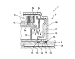
- FIG. 8 is a diagram schematically showing the forward / reverse switching device 1 mounted on a vehicle.
- the forward / reverse switching device 1 is composed mainly of a conventionally known planetary gear mechanism 2 so that the rotational direction of power input from the engine 3 can be selectively reversed and output. It is configured.
- the configuration of the planetary gear mechanism 2 shown in the drawing will be briefly described.
- the ring gear 2R that is an internal gear
- the sun gear 2S that is arranged coaxially with the ring gear 2R
- the gears 2R and 2S that mesh with each other to rotate.
- a housing 6 configured to rotate integrally with an input shaft 5 for transmitting torque from the engine 3 and inputting the torque to the forward / reverse switching device 1 is provided, and the housing 6 and the ring gear are provided. 2R is connected. That is, the ring gear 2 ⁇ / b> R is an input element of the planetary gear mechanism 2. And in order to reverse the rotation direction of the motive power input into the planetary gear mechanism 2, the brake B1 is connected with the carrier 2C. Therefore, when the brake B1 is applied, the revolution operation of the pinion gear 2P is restricted, and the rotation direction of the sun gear 2S is reversed.
- the configuration of the brake B1 shown in the figure is the same as that conventionally known. With this configuration, it is possible to selectively switch the rotation direction of the sun gear 2S and output power depending on whether or not the rotation of the carrier 2C is restricted. That is, the traveling direction of the vehicle can be switched.
- the housing 6 described above includes a cylindrical portion 6 a formed along the outer peripheral surface of the input shaft 5, an end portion on the input side of the cylindrical portion 6 a, That is, the side plate portion 6b formed by bending the right end portion shown in the figure to the outer peripheral side and the outer end portion of the side plate portion 6b are bent to the output side in the axial direction, that is, the left side shown in the drawing.
- the cylindrical portion 6a is coupled to the input shaft 5 by a fastening member (not shown) or welding.
- the outer peripheral wall portion 6c of the housing 6 is connected to an engaging portion 8 that is formed integrally with the ring gear 2R and has a plurality of plates 8a, 8a that are formed at intervals in the axial direction.
- the above-described sun gear 2S is integrally formed with an engaging portion 9 having a plurality of other plates 9a, 9a configured to be sandwiched between the plates 8a, 8a.
- the piston 10 disposed so as to be movable in the axial direction along the outer peripheral surface of the cylindrical portion 2a has a predetermined distance from the side plate portion 6b of the housing 6. It is arranged in the space.
- the piston 10 is configured to press the engaging portion 8 formed integrally with the ring gear 2R in the axial direction, and the engaging portion 8 of the ring gear 2R is disposed on the outer peripheral side of the piston 10 in the radial direction. Is bent to the output side in the axial direction. Then, in order to move the piston 10 in the axial direction, hydraulic pressure is supplied to the gap between the side plate portion 6b of the housing 6 and the piston 10, and the load for moving the piston 10 in the axial direction changes according to the hydraulic pressure. It is configured. That is, the gap between the side plate portion 6b and the piston 10 is defined as a hydraulic chamber 11, and the hydraulic pressure of the hydraulic chamber 11 is controlled to control the pressing force that presses the engaging portion 8 of the ring gear 2R. .
- the spring 12 disposed on the left side of the piston 10 shown in the drawing is a so-called return spring that constantly applies an elastic force to the piston 10 in order to move the piston 10 to the input side, that is, the right side shown in the drawing.
- the ring gear 2R and the sun gear 2S are increased by increasing the hydraulic pressure in the hydraulic chamber 11 and increasing the pressing force of the engaging portion 8.
- the ring gear 2R and the sun gear 2S can rotate together. That is, the output shaft 4 can be rotated in the same direction as the rotation direction of the input shaft 5.
- the period during which the hydraulic pressure in the hydraulic chamber 11 is maintained at a high pressure is long.
- the input shaft 5 described above is a cylindrical member having a hollow rotation center, and an oil pump (not shown) is connected to the hollow portion 5a.
- a flow path 13 that communicates with the outer peripheral surface of the input shaft 5 from the hollow portion 5 a and opens toward the hydraulic chamber 11 is formed. Therefore, the oil discharged from the oil pump is supplied to the hydraulic chamber 11 through the hollow portion 5 a of the input shaft 5.
- Seal rings 15 configured so as to be able to be arranged are arranged on both sides in the axial direction of an oil passage communicating from the input shaft 5 to the hydraulic chamber 11.
- the housing 6 is assembled in a state in which the seal ring 15 is fitted to the outer peripheral surface of the input shaft 5. For this reason, the seal for fitting the seal ring 15 to the outer peripheral surface of the input shaft 5 is configured.
- Grooves 16 are formed in the circumferential direction.
- the outer diameter of the seal ring 15 is formed to be larger than the diameter of the inner peripheral surface of the cylindrical portion 6a of the housing 6. Therefore, after the housing 6 is assembled, the inner peripheral surface of the cylindrical portion 6a of the housing 6 is assembled. Further, the outer peripheral surface of the seal ring 15 is configured to be pressed by an elastic force.
- 1 to 6 are views for explaining an example of a seal structure according to the present invention.
- the seal structure according to the present invention when the temperature of the seal ring 15 is normal temperature or lower, the gap between the input shaft 5 and the housing 6 is sealed to suppress oil leakage, and the temperature of the seal ring 15 is high. In this case, the oil is allowed to flow out from the fracture portions 17 and 19 formed in a part of the seal ring 15 in the circumferential direction.
- the configuration of the seal ring 15 shown in the drawing will be specifically described. First, a groove 18 penetrating in the axial direction is formed on the inner peripheral side in the thickness direction of the seal ring 15.
- the width of the groove 18, that is, the gap between the surfaces that are fractured and face each other, is set to such an extent that the surfaces do not contact even when the seal ring 15 is thermally expanded.
- the height of the groove 18 is such that the seal ring 15 is fitted into the seal groove 16 described above, and the housing 6 is assembled to the input shaft 5, and the input shaft 5 is inserted into the gap between the input shaft 5 and the housing 6. 5 is set so as to be located at the center side. That is, when the seal ring 15 contacts the inner wall surface of the seal groove 16, the groove 18 is configured to be sealed by the inner wall surface.
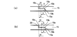
- the outer peripheral side in the thickness direction of the seal ring 15 is broken along the axial direction, and the broken portion is formed in a state bent in a crank shape. That is, the fracture portion 19 formed on the outer peripheral side of the seal ring 15 includes a first fracture portion 19a having a predetermined length in the circumferential direction of the seal ring 15 and the first fracture portion 19a as shown in FIG.
- a second fractured portion 19b formed over the oil passage side (hereinafter simply referred to as a high hydraulic pressure side) through which oil flows into the hydraulic chamber 11 from one end of the first and the other end of the first fractured portion 19a
- a third fracture portion 19c formed over the side from which the oil is discharged hereinafter simply referred to as the low hydraulic pressure side).
- FIG. 2A shows a state in which the seal ring 15 is at room temperature or lower
- FIG. 2B shows a state in which the seal ring 15 is thermally expanded at a high temperature
- the seal ring 15 is configured such that movable pieces 15a and 15b having a predetermined length in the circumferential direction formed as shown in FIGS. 3 and 4 overlap in the width direction.
- the gap between the end surface 15c of the distal end portion of the movable piece 15b on the low hydraulic pressure side and the surface 15d facing the end surface 15c, that is, the third fractured portion 19c is caused when the seal ring 15 is hot and thermally expands.
- the surfaces 15c and 15d are set so as not to contact each other.
- the gap between the end surface 15e at the tip of the movable piece 15a on the high hydraulic pressure side and the surface 15f facing the end surface 15e, that is, the second fractured portion 19b, is caused when the seal ring 15 is thermally expanded and thermally expanded.
- These surfaces 15e and 15f are set so as to be pressed against each other.
- tip part of the movable piece 15a by the side of high hydraulic pressure, and the surface 15f facing the end surface 15e are formed in the shape of a slope, and a load acts in the direction which those surfaces 15e and 15f contact.
- the movable piece 15a located on the high hydraulic pressure side is configured to receive a load on the high hydraulic pressure side.
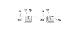
- 5 and 6 show a VV cross section and a VI-VI cross section in FIG. 2, in which (a) shows a state at room temperature or lower, and (b) shows a state at high temperature.
- the arrow shown to a figure has shown the flow of oil. Since one end face of the seal ring 15 described above is in contact with oil staying in the gap 14 between the input shaft 5 and the housing 6, the temperature of the oil is transmitted. Therefore, the temperature of the seal ring 15 changes due to the temperature of the oil. Further, the hydraulic pressure stays in the gap 14 between the input shaft 5 and the housing 6, and the hydraulic pressure acts from the high hydraulic pressure side and is pressed against one inner wall surface of the seal groove 16.
- the seal ring 15 when the seal ring 15 is below normal temperature, that is, when the oil temperature is below normal temperature, the outer peripheral surface of the seal ring 15 and the inner wall surface of the cylindrical portion 6 a of the housing 6 are pressed by the elastic force of the seal ring 15.
- the low pressure side surface of the seal ring 15 and the inner wall surface of the seal groove 16 are pressed and brought into contact with each other, and the movable pieces 15a and 15b are in contact with each other.
- the gap 14 is sealed in a liquid-tight state.
- the seal ring 15 when the seal ring 15 is hot, that is, when the temperature of the oil is high, the seal ring 15 is thermally expanded. Therefore, the end surface 15e of the distal end portion of the movable piece 15a on the high hydraulic pressure side and the surface facing the end surface 15e 15f contacts and presses each other, and the movable piece 15a is deformed to the high hydraulic pressure side. That is, the seal ring 15 is deformed by a load in the twisting direction. Therefore, the contact surface where the movable pieces 15a and 15b are in contact with each other is separated as shown in FIG.
- the oil staying in the gap 14 between the input shaft 5 and the housing 6 flows from the inner peripheral side groove 18 in the thickness direction of the seal ring 15 through the first breakage portion 19a and the third breakage portion 19c. It is discharged into the gap 14 on the side. As a result, it is possible to suppress or prevent an excessive temperature rise due to oil retention, so that it is possible to suppress or prevent deterioration of the oil. If the seal ring 15 is thermally expanded and deformed when the temperature is high, not only the movable piece 15a but also the entire sealing 15 is twisted. Therefore, in addition to the third fracture portion 19c, the third fracture portion 19c The vicinity of the opening on the low hydraulic pressure side is separated from the seal groove 16 to form a gap 20. As a result, oil can be discharged also from the gap 20.
- FIG. 7 is a diagram for explaining another configuration example, and the basic configuration is the same as the first configuration described above.
- grooves 21 and 22 having a predetermined depth are formed on the outer peripheral portions of the respective movable pieces 15a and 15b, and the end surface 15e of the distal end portion of the movable piece 15a on the high hydraulic pressure side is formed.
- the gap between the end face 15e and the face 15f facing the end face 15e is set so as not to contact when the movable piece 15a is thermally expanded.
- the grooves 21 and 22 formed in the respective movable pieces 15a and 15b are configured to be displaced in the circumferential direction when the seal ring 15 is at a low temperature, and when the seal ring 15 is thermally expanded at a high temperature.
- the grooves 21 and 22 are configured to coincide with each other in the circumferential direction so that a flow path is formed in the thickness direction.
- the seal structure according to the present invention is not limited to the above-described configuration examples.
- the seal structure can be in a liquid-tight state when the seal ring 15 is at a low temperature, and the seal structure is What is necessary is just to be comprised so that oil may be discharged
- FIG. Therefore, the member to which the seal ring 15 is attached may be a member that rotates like the input shaft 5 described above, or may be a member whose rotation operation is limited.
- the seal ring which suppresses the leakage of oil is made into object, it is not limited to this, It is good also considering the seal ring which suppresses leakage of gas, such as air. That is, a seal ring that suppresses fluid leakage can be targeted.
Landscapes
- Engineering & Computer Science (AREA)
- General Engineering & Computer Science (AREA)
- Mechanical Engineering (AREA)
- Sealing Devices (AREA)
- Transmissions By Endless Flexible Members (AREA)
- Gasket Seals (AREA)
Abstract
Description
Claims (6)
- 二つの部材の間に介在させられたシールリングによって、これらの部材同士の間の隙間を液密状態もしくは気密状態に封止するシール構造において、
流体圧を受けて前記封止状態を維持しかつ熱膨張して相対移動することにより前記封止を解除する可動部が前記シールリングに設けられていることを特徴とするシール構造。 - 前記可動部は、前記シールリングの幅方向に重なり合いかつ長手方向に互いに摺動する一対の可動片と、熱膨張してそれらの可動片が相対的に長手方向に摺動した場合にその熱応力によってそれらの可動片を互いに離隔させるガイド部とを有し、
前記シールリングには、互いに離隔した前記可動片同士の間に開口する連通部が形成されている
ことを特徴とする請求項1に記載のシール構造。 - 前記ガイド部は、前記一方の可動片の先端部に形成され、該一方の可動片の長手方向に向けた熱応力に基づいて前記シールリングの幅方向で外側に向けた分力を生じさせる傾斜面部と、その傾斜面部の先端側に該傾斜面部と対向するように形成された、傾斜受け面とを有することを特徴とする請求項2に記載のシール構造。
- 前記二つの部材のうちの一方の部材に形成され、前記シールリングが嵌め込まれたシール溝を更に備え、
前記シールリングは、他方の部材に密着するとともに、前記シール溝の一方の内側壁面に流体圧で押し付けられて密着することにより、前記二つの部材同士の間の隙間を封止していることを特徴とする請求項1ないし3のいずれかに記載のシール構造。 - 前記シールリングは、前記各部材に密着して前記二つの部材同士の間の隙間を封止し、
前記可動部は、前記シールリングの一部をいずれか一方の部材から離隔させて隙間を生じさせるように構成されている
ことを特徴とする請求項1ないし4のいずれかに記載のシール構造。 - 前記他方の可動片の先端部の端面と該端面と対向する面との間に形成された隙間が、前記傾斜面部と前記傾斜受け面とが接触するときに、前記他方の可動片の先端部の端面と該端面と対向する面とが接触しないように構成されていることを特徴とする請求項3ないし5のいずれかに記載のシール構造。
Priority Applications (5)
| Application Number | Priority Date | Filing Date | Title |
|---|---|---|---|
| PCT/JP2011/059693 WO2012144024A1 (ja) | 2011-04-20 | 2011-04-20 | シール構造 |
| DE112011100047.2T DE112011100047B8 (de) | 2011-04-20 | 2011-04-20 | Dichtstruktur |
| JP2011549375A JP5170326B2 (ja) | 2011-04-20 | 2011-04-20 | シール構造 |
| CN201180002317.3A CN102844596B (zh) | 2011-04-20 | 2011-04-20 | 密封结构 |
| US13/375,398 US8876116B2 (en) | 2011-04-20 | 2011-04-20 | Sealing structure |
Applications Claiming Priority (1)
| Application Number | Priority Date | Filing Date | Title |
|---|---|---|---|
| PCT/JP2011/059693 WO2012144024A1 (ja) | 2011-04-20 | 2011-04-20 | シール構造 |
Publications (1)
| Publication Number | Publication Date |
|---|---|
| WO2012144024A1 true WO2012144024A1 (ja) | 2012-10-26 |
Family
ID=47041174
Family Applications (1)
| Application Number | Title | Priority Date | Filing Date |
|---|---|---|---|
| PCT/JP2011/059693 WO2012144024A1 (ja) | 2011-04-20 | 2011-04-20 | シール構造 |
Country Status (5)
| Country | Link |
|---|---|
| US (1) | US8876116B2 (ja) |
| JP (1) | JP5170326B2 (ja) |
| CN (1) | CN102844596B (ja) |
| DE (1) | DE112011100047B8 (ja) |
| WO (1) | WO2012144024A1 (ja) |
Cited By (1)
| Publication number | Priority date | Publication date | Assignee | Title |
|---|---|---|---|---|
| KR102116475B1 (ko) * | 2020-02-24 | 2020-05-28 | 피에스케이 주식회사 | 실링 유지 부재 및 기판 처리 장치 |
Families Citing this family (5)
| Publication number | Priority date | Publication date | Assignee | Title |
|---|---|---|---|---|
| FR3022005B1 (fr) * | 2014-06-06 | 2016-07-08 | Vianney Rabhi | Raccord d'etancheite tournant haute-pression a bague continue extensible |
| JP6447461B2 (ja) * | 2015-11-04 | 2019-01-09 | 株式会社デンソー | シールリング |
| CN108779860A (zh) * | 2016-05-13 | 2018-11-09 | Nok株式会社 | 密封圈 |
| CN109791063B (zh) * | 2016-10-20 | 2021-03-30 | 爱知时计电机株式会社 | 流量计 |
| CN108131216B (zh) * | 2017-12-25 | 2024-03-19 | 潍柴动力股份有限公司 | 活塞环及发动机 |
Citations (2)
| Publication number | Priority date | Publication date | Assignee | Title |
|---|---|---|---|---|
| JPH0317471U (ja) * | 1989-07-04 | 1991-02-21 | ||
| JPH08338538A (ja) * | 1995-06-09 | 1996-12-24 | Honda Motor Co Ltd | 油圧シール装置 |
Family Cites Families (19)
| Publication number | Priority date | Publication date | Assignee | Title |
|---|---|---|---|---|
| US1369104A (en) * | 1919-02-20 | 1921-02-22 | Gustaf A Hendrickson | Piston-ring |
| US3655208A (en) * | 1970-04-13 | 1972-04-11 | Mc Donnell Douglas Corp | Split piston ring and method of manufacture |
| US4189161A (en) * | 1978-08-28 | 1980-02-19 | Muskegon Piston Ring Company | Bi-directional ring gap seal |
| JPS5836660U (ja) * | 1981-09-02 | 1983-03-10 | エヌオーケー株式会社 | バツクアツプリング |
| JPS59126158U (ja) * | 1983-02-12 | 1984-08-24 | 株式会社リケン | 往復動内燃機関用ピストン |
| JPS6049166A (ja) * | 1983-08-25 | 1985-03-18 | Abo Packing Seisakusho:Kk | はぎ合わせガスケツト |
| GB2162899B (en) * | 1984-06-27 | 1988-06-15 | Toshiba Kk | Scroll compressors |
| JPH02110754U (ja) * | 1989-02-21 | 1990-09-05 | ||
| US5071142A (en) * | 1989-03-31 | 1991-12-10 | Leber Corporation | Bi-directional substantially zero leakage path sealing assembly |
| JPH06281004A (ja) * | 1993-03-30 | 1994-10-07 | Nippon Piston Ring Co Ltd | 圧力リング |
| JPH06281007A (ja) * | 1993-03-30 | 1994-10-07 | Nippon Piston Ring Co Ltd | 圧力リング |
| JPH0777278A (ja) * | 1993-09-08 | 1995-03-20 | Aisin Seiki Co Ltd | ピストンシール |
| JP3324887B2 (ja) | 1994-11-08 | 2002-09-17 | 本田技研工業株式会社 | 油圧シール装置 |
| JPH09159026A (ja) * | 1995-12-08 | 1997-06-17 | Rongu Well Japan Kk | ピストンリング |
| JP2004190796A (ja) * | 2002-12-12 | 2004-07-08 | Nok Corp | シールリング |
| JP4386349B2 (ja) * | 2003-06-03 | 2009-12-16 | Ntn株式会社 | 車輪用軸受装置 |
| JP2007071329A (ja) * | 2005-09-08 | 2007-03-22 | Nok Corp | バックアップリング |
| JP5029044B2 (ja) * | 2007-02-01 | 2012-09-19 | Nok株式会社 | シールリング |
| WO2010021218A1 (ja) | 2008-08-20 | 2010-02-25 | トヨタ自動車株式会社 | 油圧制御装置 |
-
2011
- 2011-04-20 DE DE112011100047.2T patent/DE112011100047B8/de not_active Expired - Fee Related
- 2011-04-20 WO PCT/JP2011/059693 patent/WO2012144024A1/ja active Application Filing
- 2011-04-20 JP JP2011549375A patent/JP5170326B2/ja not_active Expired - Fee Related
- 2011-04-20 CN CN201180002317.3A patent/CN102844596B/zh not_active Expired - Fee Related
- 2011-04-20 US US13/375,398 patent/US8876116B2/en not_active Expired - Fee Related
Patent Citations (2)
| Publication number | Priority date | Publication date | Assignee | Title |
|---|---|---|---|---|
| JPH0317471U (ja) * | 1989-07-04 | 1991-02-21 | ||
| JPH08338538A (ja) * | 1995-06-09 | 1996-12-24 | Honda Motor Co Ltd | 油圧シール装置 |
Cited By (1)
| Publication number | Priority date | Publication date | Assignee | Title |
|---|---|---|---|---|
| KR102116475B1 (ko) * | 2020-02-24 | 2020-05-28 | 피에스케이 주식회사 | 실링 유지 부재 및 기판 처리 장치 |
Also Published As
| Publication number | Publication date |
|---|---|
| CN102844596A (zh) | 2012-12-26 |
| DE112011100047B8 (de) | 2014-05-08 |
| JP5170326B2 (ja) | 2013-03-27 |
| CN102844596B (zh) | 2014-09-03 |
| US8876116B2 (en) | 2014-11-04 |
| DE112011100047B4 (de) | 2014-01-23 |
| JPWO2012144024A1 (ja) | 2014-07-28 |
| US20140035237A1 (en) | 2014-02-06 |
| DE112011100047T5 (de) | 2013-03-21 |
Similar Documents
| Publication | Publication Date | Title |
|---|---|---|
| JP5170326B2 (ja) | シール構造 | |
| CN108700181B (zh) | 可切换速度的减速机 | |
| JP6489039B2 (ja) | 自動変速機 | |
| JP5708808B2 (ja) | 切替バルブ | |
| TW201831347A (zh) | 車輛用動力傳達裝置 | |
| WO2012127651A1 (ja) | ベルト式無段変速機 | |
| JP2015222100A (ja) | 変速機のブレーキ装置 | |
| US8051763B2 (en) | Hydraulic apparatus | |
| CN108700136B (zh) | 自动变速器 | |
| JP2009250276A (ja) | 走行車両用歯車式無段変速機。 | |
| US20160178036A1 (en) | Toroidal infinitely variable transmission | |
| JP2013228052A (ja) | 油圧制御装置 | |
| JP2011058543A (ja) | 油圧制御装置 | |
| JP5045805B2 (ja) | トロイダル型無段変速機 | |
| JP4714549B2 (ja) | 複式クラッチ装置 | |
| JP2021143672A (ja) | 油圧クラッチ | |
| JP2001065652A (ja) | ベルト式無段変速機 | |
| KR101569859B1 (ko) | 발진장치 | |
| JP2006144880A (ja) | トロイダル型無段変速機 | |
| JP7189703B2 (ja) | 油圧供給装置 | |
| JP7129301B2 (ja) | 摩擦係合装置 | |
| JP2015117774A (ja) | 変速機の油路構造 | |
| JP2021060053A (ja) | 車両用油圧シリンダ装置 | |
| JP2012097867A (ja) | 回転軸のシール構造 | |
| JP2013221608A (ja) | 油圧制御装置 |
Legal Events
| Date | Code | Title | Description |
|---|---|---|---|
| WWE | Wipo information: entry into national phase |
Ref document number: 201180002317.3 Country of ref document: CN |
|
| ENP | Entry into the national phase |
Ref document number: 2011549375 Country of ref document: JP Kind code of ref document: A |
|
| WWE | Wipo information: entry into national phase |
Ref document number: 13375398 Country of ref document: US Ref document number: 1120111000472 Country of ref document: DE Ref document number: 112011100047 Country of ref document: DE |
|
| WWE | Wipo information: entry into national phase |
Ref document number: 2581/MUMNP/2011 Country of ref document: IN |
|
| 121 | Ep: the epo has been informed by wipo that ep was designated in this application |
Ref document number: 11864082 Country of ref document: EP Kind code of ref document: A1 |
|
| 122 | Ep: pct application non-entry in european phase |
Ref document number: 11864082 Country of ref document: EP Kind code of ref document: A1 |