WO2012144017A1 - Support de transmission - Google Patents
Support de transmission Download PDFInfo
- Publication number
- WO2012144017A1 WO2012144017A1 PCT/JP2011/059610 JP2011059610W WO2012144017A1 WO 2012144017 A1 WO2012144017 A1 WO 2012144017A1 JP 2011059610 W JP2011059610 W JP 2011059610W WO 2012144017 A1 WO2012144017 A1 WO 2012144017A1
- Authority
- WO
- WIPO (PCT)
- Prior art keywords
- transmission
- transmission line
- lines
- line
- transmission lines
- Prior art date
Links
Images


Classifications
-
- H—ELECTRICITY
- H01—ELECTRIC ELEMENTS
- H01B—CABLES; CONDUCTORS; INSULATORS; SELECTION OF MATERIALS FOR THEIR CONDUCTIVE, INSULATING OR DIELECTRIC PROPERTIES
- H01B11/00—Communication cables or conductors
- H01B11/005—Quad constructions
Definitions
- the present invention relates to a transmission medium for transmitting signals and power.
- a transmission line such as a coaxial cable or a conductor
- the voltage responsible for the signal or power is attenuated or delayed due to the resistance component or inductance component of the transmission line.
- the signal is deteriorated (reduction in signal strength, phase shift) on the reception side and that power loss occurs on the power reception side.
- Designing a transmission path so that the attenuation and delay are minimized and the transmission characteristics are optimal is an important issue from the viewpoint of improving communication quality and effective use of energy.
- Patent Document 1 The invention described in Patent Document 1 is referred to as “the previous patent invention”.
- the transmission medium according to the above proposal is the longitudinal direction of the first and second conductors (lines # 1, # 2) spaced apart from each other and arranged substantially in parallel.
- the first and second conductors are wound so that the third conductor (line # 3) is alternately entangled with each other, and is further symmetrical with the shape of the wound third conductor.
- it is a transmission medium in which the fourth conductor (line # 4) is alternately wound in the longitudinal direction, and by using such a transmission medium, signal attenuation and delay are reduced as compared with the conventional one. Experiments have shown that it can be significantly reduced.
- the present inventor made a new problem to obtain a transmission medium having characteristics superior to those of the above-mentioned patented invention, and continued research by designing and prototyping transmission media with various configurations. . As a result, a transmission medium having a smaller voltage attenuation and delay than that of the transmission medium has been successfully produced.
- the transmission medium of the present invention includes first and second transmission lines arranged in parallel and spaced apart from each other, and the first and second transmission lines in the longitudinal direction of the first and second transmission lines. In the longitudinal direction of the third transmission line and the first and second transmission lines, the first and second transmission lines are alternately entangled with each other.
- the fourth transmission line wound in a superimposed manner on the third transmission line, and alternately in the longitudinal direction of the first and second transmission lines, with respect to the first and second transmission lines.
- a fifth transmission line wound while forming an intersecting portion intersecting the third and fourth transmission lines in a region sandwiched between the first and second transmission lines.
- the entanglement portion for the transmission line and the entanglement portion for the second transmission line by the fifth and sixth transmission lines are alternately formed in the longitudinal direction of the second transmission line, and the third transmission line and the fifth transmission line
- the transmission lines are commonly connected on the input end side and the output end side
- the fourth transmission line and the sixth transmission line are commonly connected on the input end side and the output end side.
- Attenuation and delay when transmitting a signal and power can be further reduced than attenuation and delay during transmission using the transmission medium according to the previous patent invention.
- transmission medium according to an embodiment of the present invention is used, transmission using the transmission medium according to the above-described patented invention manufactured using an equivalent conductive material.
- the signal delay can be reduced by about 13%.
- “arranged in parallel” does not necessarily mean that the first and second transmission lines maintain a completely parallel positional relationship over the entire length of each. It is used in the sense of being arranged substantially in parallel.
- the actual positional relationship between the first and second transmission lines according to the manufacturing technology limitations when forming each transmission line into a desired shape and arranging both transmission lines in the desired positional relationship. Can change.
- the transmission medium is fixed only at the connection terminals of both devices. That is, the transmission medium is not particularly fixed except at both ends thereof, and the parallel positional relationship in the first and second transmission lines is not completely maintained. Even when it is used in the mode, it has been shown that the transmission characteristics of the transmission medium of the present invention are improved over the previous patented invention.
- the fourth transmission line that is wound in a superimposed manner on the third transmission line means that the third and fourth transmission lines extend over the entire length of each. It does not necessarily mean that the positional relationship is completely overlapped, but it is used in the sense that the paths around which these transmission lines are wound substantially overlap.
- the actual positional relationship between the third and fourth transmission lines can vary depending on the manufacturing technology limit when winding each transmission line, the installation conditions of the transmission medium during use, and the like.
- the transmission medium is not particularly fixed except at both ends thereof in performing the experiments described in the embodiments described later, and between the third and fourth transmission lines and the fifth and sixth transmission lines. Even in the case of using in this manner, the transmission characteristics of the transmission medium of the present invention are improved over the previous patented invention. It has been shown.
- the intersecting portion is formed such that one of the third and fourth transmission line sets and the fifth and sixth transmission line sets is located above and intersects the other.
- the transmission line group located above is connected to the first or second transmission line as it travels in both directions away from each other in each direction away from the intersection on the transmission line group located above.
- Each of the first and second transmission lines is entangled from the lower side of the line to the upper side, and the lower transmission line group is separated from the intersection on the lower transmission line group.
- it is preferable to entangle with each of the first and second transmission lines so as to go from the upper side to the lower side of the first or second transmission line as it goes in both directions away from each other. .
- the 3rd, 4th transmission line group will be the 5th, 6th transmission line group, and 1st, 2nd.
- the fifth and sixth transmission line sets are sandwiched from above and below by the third, fourth and first and second transmission line sets. It will be sandwiched.
- All the first to sixth transmission lines are sandwiched from above and below by transmission lines other than the self at the entangled portion or the intersection portion, and each transmission line is strongly fixed.
- “upper” and “lower” refer to one arbitrarily selected from two directions perpendicular to the plane including the first transmission line and the second transmission line, and the other. Say.
- the lengths of the third to sixth transmission lines are preferably configured to be equal.
- the lengths are configured to be equal does not necessarily mean that the lengths of all the third to sixth transmission lines are configured to be completely the same, but are substantially equal. It is used in the sense of a degree. Similar to the “parallel” positional relationship in the first and second transmission lines, the third to sixth transmissions are performed in accordance with the manufacturing technical limit when forming each transmission line to a desired length. The actual relationship in line length can vary. However, from the viewpoint of impedance matching in the two transmission lines, it is preferable to eliminate variations in length in the third to sixth transmission lines as much as possible.
- both ends of the first transmission line and the second transmission line that are commonly connected are connected to a reference potential point, and the third transmission line that is commonly connected Connect one end of the fifth transmission line to one terminal of the signal or power source, and connect the other end of the third transmission line and the fifth transmission line connected in common to one terminal of the receiver.
- One end of the commonly connected fourth transmission line and the sixth transmission line is connected to the other terminal of the signal or power source, and the other end of the commonly connected fourth transmission line and the sixth transmission line Is connected to the other terminal of the receiver to provide a method of transmitting the signal or power from the signal or power source to the receiver using the third to sixth transmission lines as transmission paths.
- the above method is a typical aspect of signal or power transmission using the transmission medium of the present invention.
- the transmission by the transmission medium of the present invention may be power transmission by flowing current using the transmission medium of the present invention formed from a metal wire or the like, or any communication such as an optical fiber cable.
- the transmission method of the present invention can also be implemented by transmitting a communication signal after forming the transmission medium of the present invention using a wire.
- the transmission medium of the present invention If the transmission medium of the present invention is used, signals and power can be transmitted while suppressing attenuation and delay as compared with the conventional case. Thereby, it is possible to perform telecommunication with higher quality than before and power transmission with low loss.
- FIG. 2 is a schematic diagram illustrating a simplified configuration of a transmission medium according to an embodiment of the present invention, and further illustrating a common connection between transmission lines and a state of connection to each terminal and the like in use. . It is a top view of a part of transmission medium concerning a 2nd embodiment of the present invention. It is a top view of a part of transmission medium concerning a 3rd embodiment of the present invention. It is the schematic block diagram which showed the connection aspect of the function generator and each channel of an oscilloscope in the measurement experiment of the transmission characteristic performed about the transmission medium of this invention.
- the square wave signal is input to the first channel (CH1) of the oscilloscope via a coaxial cable having a total length of 1 m, and a commercially available cable having a total length of 5 m (conforming to the AWG20 standard) in the second channel (CH2).
- the square wave signal is inputted through two twisted pair wires. It is a waveform diagram observed with an oscilloscope when a square wave signal is input from the function generator to the oscilloscope.
- the square wave signal is input to the first channel (CH1) of the oscilloscope via a coaxial cable having a total length of 1 m, and the square wave is input to the first channel (CH2) via a coaxial cable having a total length of 5 m.
- a signal is being input.
- the square wave signal is input to the first channel (CH1) of the oscilloscope via a coaxial cable having a total length of 1 m, and the transmission of the total length of 5 m according to the above-mentioned patented invention is transmitted to the second channel (CH2).
- the square wave signal is input through the medium. It is a waveform diagram observed with an oscilloscope when a square wave signal is input from the function generator to the oscilloscope.
- the square wave signal is input to the first channel (CH1) of the oscilloscope via a coaxial cable having a total length of 1 m, and the second channel (CH2) is transmitted via the transmission medium having a total length of 5 m according to the present invention.
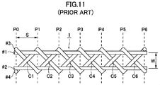
- the square wave signal is input. It is a top view of a part of transmission medium according to the previous patent invention.
- the configuration of the transmission medium and the transmission method according to the present invention will be described below with reference to the drawings.
- the specific configuration of the transmission medium and the specific implementation procedure of the transmission method according to the present invention are not limited to the specific configuration and procedure described below as examples, and they are within the scope of the present invention. Can be changed as appropriate.
- the number of entanglements and intersections formed in the transmission medium of the present invention is arbitrary, and the signal or power transmission by the transmission method of the present invention is not limited to these transmissions by a square wave voltage signal. This may be done in a manner.
- symbol is attached
- FIG. 1 is a plan view illustrating a part of a transmission medium 1 according to a first embodiment of the present invention that does not include both ends.
- the transmission medium 1 includes linear first and second transmission lines (lines # 1, # 2) arranged in parallel at a predetermined interval W, and the longitudinal directions of these lines # 1, # 2. And third to sixth transmission lines (lines # 3 to # 6) wound around the lines # 1 and # 2 alternately.
- the line # 4 is wound around the line # 3 on the substantially same path as the path around which the line # 3 is wound.
- the line # 6 is the line # 5. Is wound around the line # 5 in a superimposed manner on substantially the same route as the route around which the wire is wound.
- the curve drawn by the path wound with the lines # 3 and # 4 and the curve drawn by the path wound with the lines # 5 and # 6 are relative to the center line between the lines # 1 and # 2. They are almost symmetrical.
- the entanglement positions P0 to P6 indicate the positions in the longitudinal direction of the lines # 1 and # 2 where any of the lines # 3 to # 6 forms an entanglement with the line # 1 or # 2. .
- the lines # 3 and # 4 and the lines # 5 and # 6 are entangled alternately and in the longitudinal direction, as seen from the lines # 1 and # 2. Are formed at substantially equal intervals.
- intersection positions C1 to C6 indicate positions of intersections where lines # 3 and # 4 and lines # 5 and # 6 intersect each other.
- FIG. 2 is a schematic diagram showing the overall configuration of the transmission medium 1 in a simplified manner, and further showing a state of common connection between the transmission lines and a state of connection to each terminal of the transmission medium 1 in use. is there.
- line # 1 and line # 2, line # 3 and line # 5, and line # 4 and line # 6 are connected in common at both ends.
- both ends of line # 1 and line # 2 are connected to an arbitrary reference potential point such as ground, while lines # 3 and # 5 are used as the first transmission line # 11.
- Lines # 4 and # 6 are connected between the terminals of the input / output devices as the second transmission path # 22, respectively, and carry electric signals.
- the transmission medium 1 can be used as an acoustic speaker cable.
- a conductive wire formed by coating a conductive wire made of an arbitrary conductive material such as copper or aluminum with an arbitrary insulating film is used.
- the transmission medium 1 is configured without contacting each line, the coating with the insulating film is not necessary.
- the separation distance W between the lines # 1 and # 2 was set to about 3.5 mm, and the position interval S of each entangled portion formed by the lines # 3 to # 6 was set to about 5 mm.
- the transmission medium 1 is used, these dimensions can be appropriately changed according to the use of the transmission medium 1 and the like.
- each of the entangled portions and the intersection portions is improved so as to improve the durability against the external force as the entire transmission medium by strongly fixing each of the lines # 1 to # 6.
- the formation mode is selected.
- the lines # 3 and # 4 are located below the lines # 5 and # 6 (in the present embodiment, on the back side of the sheet).
- the lines # 3 and # 4 located below the line # 1 or the line # 2 above the line # 1 or the line # 2 as they proceed in both directions away from the intersection (this embodiment)
- the lines # 1 and # 2 are entangled so as to go downward from the front side of the drawing).
- lines # 3 and # 4 are sandwiched from above and below by lines # 5 and # 6 positioned above themselves at the intersection and lines # 1 and # 2 at which the lines are entangled from above. Will be fixed firmly.
- lines # 5 and # 6 are sandwiched from below and above by lines # 3 and # 4 located below themselves at the intersection and # 1 and # 2 where the self is entangled from below at the entanglement. And firmly fixed.
- the lines # 1 and # 2 are also sandwiched from above and below by the lines # 3 and # 4 or the lines # 5 and # 6 at the respective entanglements, and are firmly fixed.
- the lines # 1 to # 6 are sandwiched from above and below by the lines other than the self at the entanglement or intersection, each line is strongly By being fixed, durability against external force is improved.
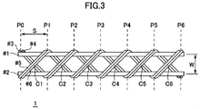
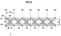
- each entangled portion and each intersecting portion in the form of formation as shown in FIG.
- the transmission medium of the present invention can be configured by forming each entangled portion and each intersecting portion in an arbitrary manner including the manner shown in FIGS. 3 and 4.
- Transmission characteristics of the transmission medium according to the present invention The transmission characteristics of the transmission medium 1 having the configuration shown in FIGS. 1 and 2 were measured.
- the square wave signal output from the function generator is input to the first channel (CH1) of the oscilloscope via a coaxial cable having a total length of 1 m, while the second channel (CH2) is input.
- the input was made through the transmission medium 1 having a total length of 5 m according to the present invention, and the waveforms observed in both channels were compared.
- the same experiment was performed while changing the transmission medium used for input to CH2 to various transmission media as comparative examples given by the prior art, and the transmission characteristics measured in each comparative example and the transmission of the present invention were compared.
- the transmission characteristics measured in the medium 1 were compared.
- FIG. 5 shows a connection mode between the function generator 10 (8116A manufactured by Hewlett Packard) and the channels CH1 and CH2 of the oscilloscope 20 (TDS420A manufactured by Tektronix) in the transmission characteristic measurement experiment.
- the length of each transmission line in FIG. 5 is not accurately reflected.
- the output terminal of the function generator 10 and the CH1 input terminal of the oscilloscope 20 are connected by a coaxial cable 30 having a total length of 1 m (compliant with JIS standard 1.5D-2V. The same applies to all coaxial cables described later).
- the output terminal of the function generator 10 and the CH2 input terminal of the oscilloscope 20 are connected by the transmission medium 1 of the present invention in the connection mode already described with reference to FIG. In both channels, a 50 ⁇ impedance matching (termination) resistor is connected.
- all of the lines # 1 to # 6 are copper wires having a wire diameter (core wire) of 0.35 mm ⁇ and a wire outer diameter (including insulating coating) of 0.4 mm ⁇ .
- Lines # 1 and # 2 are cut to a total length of 5 m (excluding the common connection portion) and arranged in parallel at an interval (W in FIG. 1) of about 3.5 mm.
- the lines # 3 to # 6 are wound around the lines # 1 and # 2 while being alternately entangled so that the interval between the entanglement positions (S in FIG. 1) is about 5 mm, and then the common connection portion (According to a simple geometric calculation, the total length of the lines # 3 to # 6 is about 6.1 m excluding the common connection portion).
- the transmission media used as comparative examples are as follows.
- (Comparative Example 1) Coaxial cable with a total length of 1 m (Comparative Example 2) Twisted pair wires made from two commercially available cables (conforming to AWG20 standard) with a total length of 5 m (Comparative Example 3) Coaxial cable with a total length of 5m (Comparative Example 4)
- a transmission medium having a total length of 5 m according to the previous patent invention having the configuration shown in FIG.
- the sizes (including the total length) and characteristics of the lines # 1 to # 4 used for the transmission medium of Comparative Example 4 are the same as those of the lines # 1 to # 6 used for the transmission medium 1 of the present invention.
- the size and characteristics of # 1 to # 4 are the same.
- the spacing W between the lines # 1 and # 2 and the spacing S between the entanglement positions are also equal in the transmission medium 1 of the present invention and the transmission medium of the comparative example 4.
- the first transmission path # 11 is formed by connecting both ends of the lines # 3 and # 4 in common, and the lines # 1 and # 2 are connected.
- any one of Comparative Examples 1 to 4 and the transmission medium 1 of the present invention is used. From the function generator 10 to each channel of the oscilloscope 20, an amplitude of 300 mV, a duty ratio of 50%, A 1 MHz square wave signal was input and the waveform was observed. Waveform diagrams of the square wave signal observed in each channel in the configuration using each transmission medium are shown in FIGS.
- FIG. 6 is a waveform diagram in each channel observed when the coaxial cable of Comparative Example 1 is used in CH2.
- the horizontal axis of the graph represents time, and the vertical axis represents voltage. Further, in order to facilitate comparison with the waveform in CH1, the waveform in CH2 is displayed with a certain offset in the downward direction of the vertical axis. Inputs to CH1 and CH2 are made through the same coaxial cable, and the waveforms in both channels are almost the same.
- the time at which the voltage of CH1 takes an intermediate value (average value of the highest and lowest values of the voltage at CH1) and the time at which the voltage of CH2 takes an intermediate value (average value of the highest and lowest values of the voltage at CH2)
- the delay time of CH2 with respect to CH1 is defined as the difference between and, the delay time is calculated to be almost zero. As a result, it can be seen that there is almost no relative signal delay due to factors other than the transmission medium used for connection to the function generator 10 between the two channels.
- FIG. 7 is a waveform diagram of each channel observed when the twisted pair wire of Comparative Example 2 is used in CH2. It can be seen from the graph that there is a relative signal delay between both channels. In addition, the waveforms observed in both channels are more distorted than in the square, and this is presumed to be due to the fact that the impedance of the transmission line is not matched between the channels. If the same definition as in FIG. 6 is used, the delay time of CH2 with respect to CH1 is calculated as 101 ns.
- FIG. 8 is a waveform diagram in each channel observed when the coaxial cable (total length: 5 m) of Comparative Example 3 is used in CH2. It can be seen from the graph that there is a relative signal delay between both channels. If the same definition as in FIG. 6 is used, the delay time of CH2 with respect to CH1 is calculated to be 47.6 ns.
- FIG. 9 is a waveform diagram in each channel observed when the transmission medium of Comparative Example 4 according to the previous patented invention is used in CH2. It can be seen from the graph that there is a relative signal delay between both channels. If the same definition as in FIG. 6 is used, the delay time of CH2 with respect to CH1 is calculated to be 46.8 ns.
- FIG. 10 is a waveform diagram in each channel observed when the transmission medium 1 of the present invention is used in CH2. It can be seen from the graph that there is a relative signal delay between both channels. If the same definition as in FIG. 6 is used, the delay time of CH2 with respect to CH1 is calculated to be 40.8 ns, and the delay time is about 13% shorter than when the transmission medium of Comparative Example 4 is used. Recognize. Further, the pulse height of the square wave signal observed at CH2 when the transmission medium 1 of the present invention shown in FIG. 10 is used is the same as that when the transmission medium of Comparative Example 4 shown in FIG. 9 is used. It is about 20 mV higher than the pulse height of the square wave signal observed at CH2.
- the transmission of the transmission medium 1 of the present invention can further reduce the attenuation of the square wave signal as compared with the transmission using the transmission medium of the previous patented invention. Furthermore, the pulse rise time was about 20 ns when the transmission medium of Comparative Example 4 according to the previous patented invention was used, but was shortened to about 12 ns when the transmission medium 1 of the present invention was used. It can be read from FIG. 9 and FIG.
- the transmission medium 1 of the present invention has transmission characteristics superior to those of various prior art transmission media, and in particular, can further reduce attenuation and delay as compared with the transmission medium according to the previous patented invention. Was shown by the measurement experiment.
- the transmission medium of the present invention can be used as a medium for transmitting any signal or power.
- an acoustic system is constructed by connecting the HOT-side terminals and the COLD-side terminals of the acoustic amplifier and the speaker with the transmission medium of the present invention, the signal attenuation and delay between devices can be reduced. Thus, it is possible to achieve a significant improvement in sound quality as compared with the conventional case.
Landscapes
- Cable Transmission Systems, Equalization Of Radio And Reduction Of Echo (AREA)
- Investigating Or Analyzing Materials By The Use Of Magnetic Means (AREA)
- Near-Field Transmission Systems (AREA)
Abstract
L'invention concerne un support de transmission qui présente de meilleures caractéristiques de transmission de signal et de puissance que les supports de transmission existants. Ce support de transmission comprend : des première et deuxième lignes de transmission écartées l'une de l'autre et parallèles entre elles ; et des troisième à sixième lignes de transmission enroulées alternativement autour de la première et de la deuxième ligne de transmission dans la direction longitudinale de manière à former des intersections, les troisième et cinquième lignes de transmission étant connectées entre elles à chaque extrémité et les quatrième et sixième lignes de transmission étant connectées entre elles à chaque extrémité. La quatrième ligne de transmission est enroulée au-dessus de la troisième ligne de transmission et la sixième ligne de transmission est enroulée au-dessus de la cinquième ligne de transmission. Les points où la troisième et la quatrième ligne de transmission s'enroulent autour de la première et de la deuxième ligne de transmission alternent, dans la direction longitudinale de la première et de la deuxième ligne de transmission, avec les points où la cinquième et la sixième ligne de transmission s'enroulent autour de la première et de la deuxième ligne de transmission.
Priority Applications (5)
| Application Number | Priority Date | Filing Date | Title |
|---|---|---|---|
| PCT/JP2011/059610 WO2012144017A1 (fr) | 2011-04-19 | 2011-04-19 | Support de transmission |
| PCT/JP2012/060138 WO2012144440A1 (fr) | 2011-04-19 | 2012-04-13 | Support, dispositif et procédé de transmission |
| JP2013510979A JPWO2012144440A1 (ja) | 2011-04-19 | 2012-04-13 | 伝送媒体、伝送装置、及び伝送方法 |
| CN201280030106.5A CN103650271A (zh) | 2011-04-19 | 2012-04-13 | 传送媒体、传送装置及传送方法 |
| TW101113724A TW201310468A (zh) | 2011-04-19 | 2012-04-18 | 傳送媒體、傳送裝置,及傳送方法 |
Applications Claiming Priority (1)
| Application Number | Priority Date | Filing Date | Title |
|---|---|---|---|
| PCT/JP2011/059610 WO2012144017A1 (fr) | 2011-04-19 | 2011-04-19 | Support de transmission |
Publications (1)
| Publication Number | Publication Date |
|---|---|
| WO2012144017A1 true WO2012144017A1 (fr) | 2012-10-26 |
Family
ID=47041167
Family Applications (2)
| Application Number | Title | Priority Date | Filing Date |
|---|---|---|---|
| PCT/JP2011/059610 WO2012144017A1 (fr) | 2011-04-19 | 2011-04-19 | Support de transmission |
| PCT/JP2012/060138 WO2012144440A1 (fr) | 2011-04-19 | 2012-04-13 | Support, dispositif et procédé de transmission |
Family Applications After (1)
| Application Number | Title | Priority Date | Filing Date |
|---|---|---|---|
| PCT/JP2012/060138 WO2012144440A1 (fr) | 2011-04-19 | 2012-04-13 | Support, dispositif et procédé de transmission |
Country Status (4)
| Country | Link |
|---|---|
| JP (1) | JPWO2012144440A1 (fr) |
| CN (1) | CN103650271A (fr) |
| TW (1) | TW201310468A (fr) |
| WO (2) | WO2012144017A1 (fr) |
Cited By (2)
| Publication number | Priority date | Publication date | Assignee | Title |
|---|---|---|---|---|
| JP6259173B1 (ja) * | 2017-01-23 | 2018-01-10 | 徹 金城 | 伝送線 |
| WO2019123664A1 (fr) * | 2017-12-23 | 2019-06-27 | 徹 金城 | Support de transmission |
Families Citing this family (1)
| Publication number | Priority date | Publication date | Assignee | Title |
|---|---|---|---|---|
| CN109659865A (zh) * | 2019-01-04 | 2019-04-19 | 中国电力科学研究院有限公司 | 一种敷设双极直流电缆的方法及系统 |
Citations (2)
| Publication number | Priority date | Publication date | Assignee | Title |
|---|---|---|---|---|
| JP2007172928A (ja) * | 2005-12-20 | 2007-07-05 | Hitachi Cable Ltd | 極細絶縁線と同軸ケーブル及びその製造方法並びにこれを用いた多芯ケーブル |
| WO2010029626A1 (fr) * | 2008-09-11 | 2010-03-18 | 菅間 リエ | Milieu de transmission |
Family Cites Families (6)
| Publication number | Priority date | Publication date | Assignee | Title |
|---|---|---|---|---|
| JPS60192429A (ja) * | 1984-03-13 | 1985-09-30 | Hitachi Cable Ltd | 誘導無線用線路 |
| JPS63257305A (ja) * | 1987-04-14 | 1988-10-25 | Matsushita Electric Works Ltd | 情報信号伝送路装置 |
| WO1999028989A1 (fr) * | 1997-12-03 | 1999-06-10 | Mitsubishi Denki Kabushiki Kaisha | Dispositif antenne combine |
| US7061342B2 (en) * | 2001-12-28 | 2006-06-13 | Molex Incorporated | Differential transmission channel link for delivering high frequency signals and power |
| JP4143086B2 (ja) * | 2005-12-20 | 2008-09-03 | 日立電線株式会社 | 極細銅合金線、極細銅合金撚線及びそれらの製造方法 |
| JP2008277174A (ja) * | 2007-04-27 | 2008-11-13 | Litehouse Technologies Corp | 発光装置及び装着用フレーム |
-
2011
- 2011-04-19 WO PCT/JP2011/059610 patent/WO2012144017A1/fr active Application Filing
-
2012
- 2012-04-13 WO PCT/JP2012/060138 patent/WO2012144440A1/fr active Application Filing
- 2012-04-13 JP JP2013510979A patent/JPWO2012144440A1/ja active Pending
- 2012-04-13 CN CN201280030106.5A patent/CN103650271A/zh active Pending
- 2012-04-18 TW TW101113724A patent/TW201310468A/zh unknown
Patent Citations (2)
| Publication number | Priority date | Publication date | Assignee | Title |
|---|---|---|---|---|
| JP2007172928A (ja) * | 2005-12-20 | 2007-07-05 | Hitachi Cable Ltd | 極細絶縁線と同軸ケーブル及びその製造方法並びにこれを用いた多芯ケーブル |
| WO2010029626A1 (fr) * | 2008-09-11 | 2010-03-18 | 菅間 リエ | Milieu de transmission |
Cited By (3)
| Publication number | Priority date | Publication date | Assignee | Title |
|---|---|---|---|---|
| JP6259173B1 (ja) * | 2017-01-23 | 2018-01-10 | 徹 金城 | 伝送線 |
| WO2018134990A1 (fr) * | 2017-01-23 | 2018-07-26 | 徹 金城 | Ligne de transmission |
| WO2019123664A1 (fr) * | 2017-12-23 | 2019-06-27 | 徹 金城 | Support de transmission |
Also Published As
| Publication number | Publication date |
|---|---|
| TW201310468A (zh) | 2013-03-01 |
| CN103650271A (zh) | 2014-03-19 |
| JPWO2012144440A1 (ja) | 2014-07-28 |
| WO2012144440A1 (fr) | 2012-10-26 |
Similar Documents
| Publication | Publication Date | Title |
|---|---|---|
| US10692639B2 (en) | Inductive component and method for producing an inductive component | |
| CN103339691B (zh) | 传输电缆 | |
| JP5558609B1 (ja) | コモンモードチョークコイル | |
| JP4335974B1 (ja) | 伝送媒体 | |
| CN102832021A (zh) | 变压器及其制造方法 | |
| WO2012078489A1 (fr) | Modèle de câble twinax pour des performances électriques améliorées | |
| US10079081B2 (en) | Low R, L, and C cable | |
| JP5454648B2 (ja) | 差動信号用ケーブル及びこれを用いた伝送ケーブル、並びに差動信号用ケーブルの製造方法 | |
| JP2020516083A (ja) | 高速データ通信用に帯域幅を拡大した磁気変圧器 | |
| JP2014099404A (ja) | 差動信号用ケーブル及びこれを用いた伝送ケーブル、並びにダイレクトアタッチケーブル | |
| WO2012144017A1 (fr) | Support de transmission | |
| JP2011258330A (ja) | ツイストペアケーブル | |
| JP2013247190A (ja) | ノイズフィルタおよび信号伝送用ケーブル | |
| JP2021034296A (ja) | 導線およびコイル部材 | |
| JP6971062B2 (ja) | 非接触給電装置用コイルおよび非接触給電装置用コイルの製造方法 | |
| JP2006352664A (ja) | 信号結合装置 | |
| JP5159269B2 (ja) | 複合電線およびコイル | |
| US11563416B2 (en) | Common mode choke coil | |
| JP4292274B2 (ja) | 小振幅作動信号用回路 | |
| JP2008226774A (ja) | 伝送媒体 | |
| JP3938373B2 (ja) | サージ抑制ユニット品 | |
| CN220543734U (zh) | 一种有效克服趋肤效应的宽频带音频变压器 | |
| KR102274227B1 (ko) | 전기 전송매체 | |
| CN107545955A (zh) | 差分信号传输用电缆以及多芯差分信号传输用电缆 | |
| JP2008079062A (ja) | 伝送システム |
Legal Events
| Date | Code | Title | Description |
|---|---|---|---|
| 121 | Ep: the epo has been informed by wipo that ep was designated in this application |
Ref document number: 11864105 Country of ref document: EP Kind code of ref document: A1 |
|
| NENP | Non-entry into the national phase |
Ref country code: DE |
|
| 122 | Ep: pct application non-entry in european phase |
Ref document number: 11864105 Country of ref document: EP Kind code of ref document: A1 |
|
| NENP | Non-entry into the national phase |
Ref country code: JP |