WO2012141128A1 - 駆動力配分装置の油圧制御装置 - Google Patents
駆動力配分装置の油圧制御装置 Download PDFInfo
- Publication number
- WO2012141128A1 WO2012141128A1 PCT/JP2012/059658 JP2012059658W WO2012141128A1 WO 2012141128 A1 WO2012141128 A1 WO 2012141128A1 JP 2012059658 W JP2012059658 W JP 2012059658W WO 2012141128 A1 WO2012141128 A1 WO 2012141128A1
- Authority
- WO
- WIPO (PCT)
- Prior art keywords
- hydraulic
- piston chamber
- oil
- pressure
- hydraulic pressure
- Prior art date
- Legal status (The legal status is an assumption and is not a legal conclusion. Google has not performed a legal analysis and makes no representation as to the accuracy of the status listed.)
- Ceased
Links
Images




Classifications
-
- F—MECHANICAL ENGINEERING; LIGHTING; HEATING; WEAPONS; BLASTING
- F15—FLUID-PRESSURE ACTUATORS; HYDRAULICS OR PNEUMATICS IN GENERAL
- F15B—SYSTEMS ACTING BY MEANS OF FLUIDS IN GENERAL; FLUID-PRESSURE ACTUATORS, e.g. SERVOMOTORS; DETAILS OF FLUID-PRESSURE SYSTEMS, NOT OTHERWISE PROVIDED FOR
- F15B15/00—Fluid-actuated devices for displacing a member from one position to another; Gearing associated therewith
- F15B15/18—Combined units comprising both motor and pump
-
- B—PERFORMING OPERATIONS; TRANSPORTING
- B60—VEHICLES IN GENERAL
- B60K—ARRANGEMENT OR MOUNTING OF PROPULSION UNITS OR OF TRANSMISSIONS IN VEHICLES; ARRANGEMENT OR MOUNTING OF PLURAL DIVERSE PRIME-MOVERS IN VEHICLES; AUXILIARY DRIVES FOR VEHICLES; INSTRUMENTATION OR DASHBOARDS FOR VEHICLES; ARRANGEMENTS IN CONNECTION WITH COOLING, AIR INTAKE, GAS EXHAUST OR FUEL SUPPLY OF PROPULSION UNITS IN VEHICLES
- B60K17/00—Arrangement or mounting of transmissions in vehicles
- B60K17/34—Arrangement or mounting of transmissions in vehicles for driving both front and rear wheels, e.g. four wheel drive vehicles
- B60K17/348—Arrangement or mounting of transmissions in vehicles for driving both front and rear wheels, e.g. four wheel drive vehicles having differential means for driving one set of wheels, e.g. the front, at one speed and the other set, e.g. the rear, at a different speed
-
- B—PERFORMING OPERATIONS; TRANSPORTING
- B60—VEHICLES IN GENERAL
- B60K—ARRANGEMENT OR MOUNTING OF PROPULSION UNITS OR OF TRANSMISSIONS IN VEHICLES; ARRANGEMENT OR MOUNTING OF PLURAL DIVERSE PRIME-MOVERS IN VEHICLES; AUXILIARY DRIVES FOR VEHICLES; INSTRUMENTATION OR DASHBOARDS FOR VEHICLES; ARRANGEMENTS IN CONNECTION WITH COOLING, AIR INTAKE, GAS EXHAUST OR FUEL SUPPLY OF PROPULSION UNITS IN VEHICLES
- B60K23/00—Arrangement or mounting of control devices for vehicle transmissions, or parts thereof, not otherwise provided for
- B60K23/08—Arrangement or mounting of control devices for vehicle transmissions, or parts thereof, not otherwise provided for for changing number of driven wheels, for switching from driving one axle to driving two or more axles
-
- B—PERFORMING OPERATIONS; TRANSPORTING
- B60—VEHICLES IN GENERAL
- B60K—ARRANGEMENT OR MOUNTING OF PROPULSION UNITS OR OF TRANSMISSIONS IN VEHICLES; ARRANGEMENT OR MOUNTING OF PLURAL DIVERSE PRIME-MOVERS IN VEHICLES; AUXILIARY DRIVES FOR VEHICLES; INSTRUMENTATION OR DASHBOARDS FOR VEHICLES; ARRANGEMENTS IN CONNECTION WITH COOLING, AIR INTAKE, GAS EXHAUST OR FUEL SUPPLY OF PROPULSION UNITS IN VEHICLES
- B60K23/00—Arrangement or mounting of control devices for vehicle transmissions, or parts thereof, not otherwise provided for
- B60K23/08—Arrangement or mounting of control devices for vehicle transmissions, or parts thereof, not otherwise provided for for changing number of driven wheels, for switching from driving one axle to driving two or more axles
- B60K23/0808—Arrangement or mounting of control devices for vehicle transmissions, or parts thereof, not otherwise provided for for changing number of driven wheels, for switching from driving one axle to driving two or more axles for varying torque distribution between driven axles, e.g. by transfer clutch
-
- B—PERFORMING OPERATIONS; TRANSPORTING
- B60—VEHICLES IN GENERAL
- B60K—ARRANGEMENT OR MOUNTING OF PROPULSION UNITS OR OF TRANSMISSIONS IN VEHICLES; ARRANGEMENT OR MOUNTING OF PLURAL DIVERSE PRIME-MOVERS IN VEHICLES; AUXILIARY DRIVES FOR VEHICLES; INSTRUMENTATION OR DASHBOARDS FOR VEHICLES; ARRANGEMENTS IN CONNECTION WITH COOLING, AIR INTAKE, GAS EXHAUST OR FUEL SUPPLY OF PROPULSION UNITS IN VEHICLES
- B60K23/00—Arrangement or mounting of control devices for vehicle transmissions, or parts thereof, not otherwise provided for
- B60K23/08—Arrangement or mounting of control devices for vehicle transmissions, or parts thereof, not otherwise provided for for changing number of driven wheels, for switching from driving one axle to driving two or more axles
- B60K2023/085—Arrangement or mounting of control devices for vehicle transmissions, or parts thereof, not otherwise provided for for changing number of driven wheels, for switching from driving one axle to driving two or more axles automatically actuated
- B60K2023/0866—Arrangement or mounting of control devices for vehicle transmissions, or parts thereof, not otherwise provided for for changing number of driven wheels, for switching from driving one axle to driving two or more axles automatically actuated with hydraulic means only
Definitions
- the present invention controls a hydraulic pressure for generating an engagement pressure of a clutch of a drive power distribution device in a drive power distribution device of a four-wheel drive vehicle that distributes the drive power from a prime mover to main drive wheels and sub drive wheels. Hydraulic control device.
- a four-wheel drive vehicle provided with a drive power distribution device for distributing a drive power generated by a drive source such as an engine to a main drive wheel and a sub drive wheel.
- a drive source such as an engine
- the drive force generated by the drive source is transmitted to the front wheel via a front drive shaft and a front differential. And is transmitted to a driving force distribution device having a multi-plate clutch via a propeller shaft. Then, the hydraulic pressure of the driving force distribution device is supplied from the hydraulic control device to control the engagement pressure of the driving force distribution device.
- the driving force of the driving source is transmitted to the rear wheels at a predetermined distribution ratio.
- Patent Documents 1 and 2 As hydraulic control devices for controlling the hydraulic pressure supplied to the multi-plate clutch of the driving force distribution device, there are hydraulic control devices shown in Patent Documents 1 and 2 conventionally.
- the hydraulic control device disclosed in Patent Documents 1 and 2 includes an electric oil pump that supplies hydraulic oil to a hydraulic chamber for pressing a multi-plate clutch, and the electric oil pump and the hydraulic chamber are connected by a hydraulic supply passage. It is a structure. Then, in the hydraulic control device of Patent Document 1, the number of rotations of the electric pump is controlled such that the discharge value of the electric pump becomes the required operating pressure of the hydraulic clutch. Further, in the hydraulic control device described in Patent Document 2, the motor drive of the electric pump is controlled to generate the hydraulic pressure according to the distribution ratio of the driving force.
- the present invention has been made in view of the above-described points, and an object thereof is to be able to reduce the operation frequency of the electric oil pump and to improve the torque accuracy of the clutch with a simple configuration and control.
- An object of the present invention is to provide a hydraulic control device of a driving force distribution device.
- the present invention for solving the above problems comprises a driving force transmission path (20) for transmitting the driving force from the driving source (3) to the main driving wheels (W1, W2) and the sub driving wheels (W3, W4)
- a four-wheel drive vehicle (1) comprising a drive power distribution device (10) disposed between a drive source (3) and an auxiliary drive wheel (W3, W4) in a drive force transmission path (20).
- the driving force distribution device (10) generates a hydraulic pressure with respect to a plurality of stacked friction members (13) and a piston (12) which presses and engages the friction members (13) in the stacking direction.
- the hydraulic control device of the driving force distribution device in accordance with the present invention, by providing the hydraulic circuit configured as described above, it is possible to seal the hydraulic oil in the oil passage between the hydraulic oil sealing valve and the piston chamber It becomes a hydraulic circuit.
- the characteristics of the hydraulic pressure applied to the piston chamber by the hydraulic circuit the first characteristic obtained by closing the on-off valve and driving the oil pump, and prohibiting the driving of the oil pump and opening the on-off valve
- the motor for driving the oil pump is intermittently operated while the engagement pressure is generated in the friction engagement element. It becomes possible to drive. Therefore, the durability can be improved by reducing the operation frequency of the motor.
- the piston chamber When the piston chamber is pressurized, the piston chamber is controlled to the target hydraulic pressure based on the first characteristic, and when the pressure in the piston chamber is reduced, the piston chamber is the target based on the second characteristic.
- the piston chamber By controlling so as to be hydraulic pressure, it is possible to switch between hydraulic pressure-torque characteristics at the time of pressurization and pressure reduction of the piston chamber.
- the torque characteristic of the frictional engagement element can be made close to a linear characteristic, so that the torque accuracy of the frictional engagement element can be improved.
- control means (50) pressurizes the piston chamber (15) to reach the target hydraulic pressure, and then stops the driving of the oil pump (35) by the motor (37),
- the engagement force of the frictional engagement element (10) may be maintained constant by the hydraulic pressure of the hydraulic fluid enclosed in the oil passage (49) until the pressure reduction of the piston chamber (15) is started.
- the piston is stopped by stopping the drive of the oil pump by the motor.
- the engagement force of the frictional engagement element can be maintained constant by the hydraulic pressure of the hydraulic fluid enclosed in the oil passage until the pressure reduction of the chamber is started. This makes it possible to intermittently operate the motor for driving the oil pump while generating the engagement pressure in the friction engagement element. Therefore, the durability can be improved by reducing the operation frequency of the motor.
- the piston chamber (the first characteristic and the second characteristic) can be obtained by performing the drive of the oil pump (35) and the opening and closing of the on-off valve (43) in stages.
- the hydraulic pressure of 15) and the torque of the clutch (10) may be controlled to change stepwise.
- the method of adjusting the hydraulic pressure step by step is adopted, it becomes possible to intermittently operate the motor for driving the oil pump even when the piston chamber is pressurized. Therefore, the durability can be improved by reducing the operation frequency of the motor.
- the hydraulic control based on the first characteristic is performed based on the relationship between the drive voltage of the motor (37) measured in advance and the discharge amount of the oil pump (35).
- the control is performed by controlling the drive voltage of the motor (37) so that (35) is a desired discharge amount
- the hydraulic control based on the second characteristic is the drive voltage and valve of the on-off valve (43) measured in advance. It may be performed by controlling the drive voltage of the on-off valve (43) so that the on-off valve (43) has a desired valve opening degree based on the relationship of the opening degree.
- the operating frequency of the motor for driving the oil pump can be reduced and the torque accuracy of the clutch can be improved with a simple configuration and control. .
- FIG. 1 It is a figure showing a schematic structure of a four-wheel drive vehicle provided with a hydraulic control device of a driving force distribution device concerning an embodiment of the present invention. It is a figure which shows the hydraulic circuit of a hydraulic control apparatus. It is a flowchart which shows the procedure of oil pressure control of a piston chamber, (a) is a flowchart which shows the procedure at the time of pressurization, (b) is a flowchart which shows the procedure at the time of pressure reduction. 5 is a timing chart showing changes in command torque and actual torque of a clutch, changes in input rotational speed to the clutch, and changes in command oil pressure and actual oil pressure of a piston chamber in hydraulic control of the piston chamber.
- FIG. 7A is a circuit diagram showing the state of hydraulic fluid in an oil passage in hydraulic control of a piston chamber, where (a) is the state of hydraulic fluid at pressure, (b) is the state of hydraulic fluid at hydraulic pressure holding, (c ) Is a figure which shows the state of the hydraulic fluid at the time of pressure reduction. It is a timing chart which shows change of the operation / stop state of a motor (oil pump) in the oil pressure control of a piston room, the open / closed state of a solenoid valve, and actual oil pressure.
- FIG. 7A is a circuit diagram showing the state of hydraulic fluid in an oil passage in hydraulic control of a piston chamber, where (a) is the state of hydraulic fluid at pressure, (b) is the state of hydraulic fluid at hydraulic pressure holding, (c ) Is a figure which shows the state of the hydraulic fluid at the time of pressure reduction. It is a timing chart which shows change of the operation / stop state of a motor (oil pump) in the oil pressure control of a piston room, the open
- FIG. 10 is a diagram showing the hydraulic pressure characteristics of the piston chamber of the clutch, and a table showing a hydraulic-torque characteristic map on the pressure side. It is a figure which shows the hydraulic circuit with which the hydraulic control apparatus concerning 2nd Embodiment of this invention is provided. It is a timing chart which shows change of an operation / stop state of a motor (oil pump) in a hydraulic control system of a 2nd embodiment, an open / closed state of the 1st and 2nd solenoid valve, and real oil pressure.
- a motor oil pump
- FIG. 1 is a view showing a schematic configuration of a four-wheel drive vehicle provided with a hydraulic control device of a driving force distribution device according to an embodiment of the present invention.
- the four-wheel drive vehicle 1 shown in the figure includes an engine (drive source) 3 mounted horizontally at the front of the vehicle, an automatic transmission 4 integrally installed with the engine 3, and driving power from the engine 3
- a driving force transmission path 20 for transmitting the front wheels W1, W2 and the rear wheels W3, W4 is provided.
- An output shaft (not shown) of the engine 3 is a main drive wheel left and right front wheels W1 via an automatic transmission 4, a front differential (hereinafter referred to as “front differential”) 5 and left and right front drive shafts 6, 6. , W2 are linked. Further, the output shaft of the engine 3 is an auxiliary drive wheel via an automatic transmission 4, front differential 5, propeller shaft 7, rear differential unit (hereinafter referred to as “rear differential unit”) 8 and left and right rear drive shafts 9, 9. It is connected to certain left and right rear wheels W3 and W4.
- the rear differential unit 8 is connected with a rear differential (hereinafter referred to as "rear differential") 19 for distributing the driving force to the left and right rear drive shafts 9, 9, and a driving force transmission path from the propeller shaft 7 to the rear differential 19.
- a front and rear torque distribution clutch 10 for disconnecting is provided.
- the front-rear torque distribution clutch 10 is a hydraulic clutch and is a drive power distribution device for controlling the drive power distributed to the rear wheels W3 and W4 in the drive power transmission path 20.
- the ECU 50 is configured of a microcomputer and the like.
- the ECU 50 controls the hydraulic pressure supplied from the hydraulic circuit 30 to control the driving force distributed to the rear wheels W3 and W4 by the front-rear torque distribution clutch (hereinafter simply referred to as "clutch") 10.
- the front wheels W1 and W2 as main drive wheels
- the rear wheels W3 and W4 as secondary drive wheels.
- the ECU 50 calculates the driving force to be distributed to the rear wheels W3 and W4 and the hydraulic pressure supply amount to the corresponding clutch 10 based on the detection of various detection means (not shown) for detecting the traveling state of the vehicle. At the same time, a drive signal based on the calculation result is output to the clutch 10. Thereby, the fastening force of the clutch 10 is controlled, and the driving force to be distributed to the rear wheels W3 and W4 is controlled.
- FIG. 2 is a hydraulic circuit diagram showing a detailed configuration of the hydraulic circuit 30.
- the hydraulic circuit 30 shown in the figure includes an oil pump 35 for drawing in and pumping hydraulic oil stored in the oil tank 31 via a strainer 33, a motor 37 for driving the oil pump 35, and the oil pump 35 to the clutch 10.
- An oil passage 49 communicating with the piston chamber 15 is provided.
- the clutch 10 includes a cylinder housing 11 and a piston 12 for pressing a plurality of friction members 13 stacked by moving back and forth in the cylinder housing 11.
- a piston chamber 15 is defined between the piston 12 and into which hydraulic fluid is introduced.
- the piston 12 is disposed to face one end of the plurality of friction members 13 in the stacking direction. Therefore, when the piston 12 presses the friction material 13 in the stacking direction by the hydraulic pressure of the hydraulic fluid supplied to the piston chamber 15, the clutch 10 is engaged at a predetermined engagement pressure.
- a check valve 39, a relief valve 41, a solenoid valve (open / close valve) 43, and an oil pressure sensor 45 are installed in this order in an oil passage 49 communicating with the piston chamber 15 from the oil pump 35.
- the check valve 39 circulates the hydraulic oil from the oil pump 35 side to the piston chamber 15 side, but is configured to block the hydraulic oil from flowing in the opposite direction.
- the hydraulic oil sent to the downstream side of the check valve 39 by the drive of the oil pump 35 is referred to as an oil passage between the check valve 39 and the piston chamber 15 (hereinafter referred to as "filled oil passage" Yes, it can be contained in 49).
- An enclosed hydraulic circuit 30 is constituted by the check valve 39 and the oil passage 49 provided with the oil pump 35.
- the check valve 39 is a hydraulic oil sealing valve for sealing the hydraulic oil in the oil passage 49 leading from the oil pump 35 to the piston chamber 15.
- the relief valve 41 is configured to release the hydraulic pressure of the oil passage 49 by opening when the pressure of the oil passage 49 between the check valve 39 and the piston chamber 15 abnormally rises above a predetermined threshold. It is a good valve.
- the hydraulic oil discharged from the relief valve 41 is returned to the oil tank 31.
- the solenoid valve 43 is an on / off type on-off valve, and can perform open / close control of the oil passage 49 by performing PWM control (duty control) based on a command of the ECU 50. Thereby, the hydraulic pressure of the piston chamber 15 can be controlled.
- the hydraulic oil discharged from the oil passage 49 is returned to the oil tank 31 when the solenoid valve 43 is opened.
- the oil pressure sensor 45 is an oil pressure detection means for detecting the oil pressure of the oil passage 49 and the piston chamber 15, and the detection value is sent to the ECU 50. Also, the piston chamber 15 communicates with the accumulator 18. The accumulator 18 has the function of suppressing sudden changes in oil pressure and oil pressure pulsation in the piston chamber 15 and the oil passage 49. Further, an oil temperature sensor 47 for detecting the temperature of the hydraulic oil is provided in the oil tank 31. The detected value of the oil temperature sensor 47 is sent to the ECU 50.
- FIG. 3 is a flowchart showing a procedure of hydraulic control by the hydraulic control device 60 of the present embodiment, where (a) is a flowchart showing a control procedure at the time of pressurization of the piston chamber 15, and (b) is a piston It is a flowchart which shows the control procedure at the time of pressure reduction of chamber
- FIG. 4 is a timing chart showing changes in command torque and actual torque of the clutch 10 when performing hydraulic control, changes in input rotational speed to the clutch 10, and changes in command hydraulic pressure and actual oil pressure of the piston chamber 15. It is.
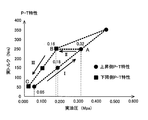
- FIG. 5 is a graph showing the relationship between the actual oil pressure and the actual torque (oil pressure-torque characteristic (PT characteristic)) in the oil pressure control of the piston chamber 15. Further, FIG.
- PT characteristic oil pressure-torque characteristic
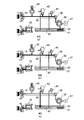
- FIG. 6 is a circuit diagram showing the state of the hydraulic fluid in the oil passage 49 in the hydraulic control of the piston chamber 15.
- FIG. The state of the hydraulic oil of (c) is a figure which shows the state of the hydraulic oil at the time of pressure reduction.
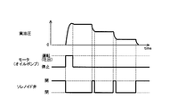
- FIG. 7 is a timing chart showing the relationship between the operating / stopping state of the motor 37 (oil pump 35) in the hydraulic control of the piston chamber 15, the open / closed state of the solenoid valve 43 and the actual hydraulic pressure.
- FIG. 8 is a diagram showing the hydraulic pressure characteristics of the piston chamber 15 of the clutch 10, and is a table showing hydraulic pressure-torque characteristics at the time of pressurization (upward side).
- the ECU 50 determines whether or not there is a pressurization instruction (pressure instruction torque) to the piston chamber 15 (step ST1-1).
- a pressurization instruction pressure instruction torque
- NO no instruction to pressurize the piston chamber 15
- the stop oil pressure (command oil pressure) of the oil pump 35 (motor 37) is calculated based on the pressure side oil pressure-torque characteristic table shown in FIG. -2)
- the duty ratio of PWM control for driving the motor 37 is determined from the calculated command hydraulic pressure (step ST1-3).
- the solenoid valve 43 is open, the solenoid valve 43 is closed to seal the oil passage 49 (step ST1-4), and the motor 37 is driven at the determined duty ratio to drive the oil pump 35.
- Step ST1-5 As a result, the hydraulic oil is fed into the oil passage 49 between the check valve 39 and the piston chamber 15, and the oil pressure of the oil passage 49 and the piston chamber 15 is increased.
- step ST1-6 it is determined whether the hydraulic pressure (actual hydraulic pressure) of the oil passage 49 and the piston chamber 15 detected by the hydraulic pressure sensor 45 is equal to or higher than the stop hydraulic pressure (instruction hydraulic pressure) of the oil pump 35 (motor 37) (step ST1-6) ).
- the oil pressure of the oil passage 49 and the piston chamber 15 reaches the stop oil pressure of the oil pump 35 (YES)
- the operation of the oil pump 35 (motor 37) is stopped (step ST1-7), and the control at the time of pressurization is ended.
- the ECU 50 determines whether or not there is a pressure reduction instruction (pressure reduction instruction torque) to the piston chamber 15 (step ST2-1).
- a pressure reduction instruction pressure reduction instruction torque
- the pressure reduction instruction to the piston chamber 15 results in the engagement release request or the engagement force of the clutch It depends on whether there is a demand for reduction of As a result, if there is no pressure reduction instruction (NO), the process ends.
- step ST2-2 the hydraulic pressure for closing the solenoid valve 43 (instruction hydraulic pressure) is calculated based on the pressure-reduction side hydraulic pressure-torque characteristic table (step ST2-2).
- step ST2-2 the hydraulic pressure for closing the solenoid valve 43
- step ST2-2 the hydraulic pressure for closing the solenoid valve 43
- step ST2-2 the hydraulic pressure for closing the solenoid valve 43
- step ST2-2 the hydraulic pressure for closing the solenoid valve 43
- step ST2-2 the solenoid valve 43 is opened to release the sealed state of the oil passage 49 (step ST2-3), and the oil pressure of the oil passage 49 and the piston chamber 15 is controlled based on the pressure reduction side oil pressure-torque characteristic.
- step ST2-4 it is determined whether the hydraulic pressure (actual hydraulic pressure) of the oil passage 49 and the piston chamber 15 detected by the hydraulic pressure sensor 45 is less than or equal to the closing hydraulic pressure (instruction hydraulic pressure) of the solenoid valve 43 (step ST2-4).
- the solenoid valve 43 is closed (step ST2-5), and the control at the time of pressure reduction is ended.
- the hydraulic pressure control by the hydraulic pressure control device 60 of the present embodiment will be described in more detail.
- the hydraulic control at the time of pressurization is performed according to the flowchart of FIG. 3A based on the pressurization side hydraulic pressure-torque characteristic until the time T2 is reached.
- the indicated hydraulic pressure of the oil passage 49 and the piston chamber 15 and the indicated torque of the clutch 10 are controlled so as to change stepwise in a plurality of stages.
- the graph of FIG. 4 illustrates only changes of the command hydraulic pressure and the command torque in two stages, actually, the command hydraulic pressure and command torque are shown in the pressure side hydraulic pressure-torque characteristic table (see FIG. 8).
- the driving force is input to the clutch 10 from the rear differential 19 side at time T1 earlier than time T2.
- the torque (actual torque) applied to the clutch 10 is increased in the section I shown in FIGS. 4 and 5.
- the actual torque rises to a value corresponding to the command torque.
- the change of the torque (actual torque) with respect to the hydraulic pressure (actual hydraulic pressure) at this time is a change with a constant inclination connecting the plots of circles in the graph of FIG.
- a characteristic indicated by a line connecting the circled plots is a pressure side (rising side) oil pressure-torque characteristic.
- the pressure-side hydraulic pressure-torque characteristic is a characteristic of inclination as shown by a circled plot in FIG.
- the hydraulic pressure feedback at the time when the hydraulic pressure instruction of each stage is started (rise time of the command hydraulic pressure). Control is started. Then, when the pressure adjustment to the target hydraulic pressure is completed, the hydraulic pressure feedback control ends.
- oil pressure feedback control by driving of the oil pump 35 and opening and closing of the solenoid valve 43 is not performed, and oil pressure change during this time depends only on sealing performance (sealing performance) of the oil passage 49.
- sealing performance sealing performance
- the torque of the clutch 10 is constant while transitioning from the pressure side torque-torque characteristic to the pressure side hydraulic pressure-torque characteristic.
- the hydraulic pressure (actual hydraulic pressure) detected by the hydraulic pressure sensor 45 reaches a point B on the pressure-reduction side hydraulic pressure-torque characteristic.
- pressure control at the time of pressure reduction is performed according to the flowchart of FIG. 3 (b) based on the pressure-reduction side oil pressure-torque characteristic.
- the instructed hydraulic pressure of the oil passage 49 and the piston chamber 15 and the instructed torque of the clutch 10 are controlled so as to change stepwise in a plurality of stages. That is, although the illustration is omitted, a map of pressure-reduction side oil pressure-torque characteristics is prepared in advance as in the case of the pressure-side oil pressure-torque characteristic map shown in FIG.
- the oil pressure of the oil passage 49 and the piston chamber 15 is controlled. Further, in the hydraulic pressure control at the time of pressure reduction, as described above, the hydraulic pressure of the piston chamber 15 is lowered to the target hydraulic pressure according to the desired torque by controlling the opening and closing of the solenoid valve 43 according to the instructed hydraulic pressure. Controlled by The hydraulic oil in the hydraulic circuit 30 at the time of pressure reduction is in the state shown in FIG.
- pressure regulation during pressurization and decompression is performed when feedback control based on the hydraulic pressure detected by the hydraulic sensor 45 is performed.
- the system is highly dependent on the hydraulic pressure sensor 45.
- the oil pump 35 and the solenoid valve 43 are duty-driven by PWM control, the degree of dependence on the hydraulic pressure sensor 45 can be reduced if open loop control is performed. As a result, the hydraulic pressure sensor 45 can be eliminated as needed.
- the hydraulic control device 60 of the present embodiment it is possible to determine the hydraulic pressure generated by the balance between the discharge amount control of the oil pump 35 by duty drive and the pressure adjustment (orifice effect) of the solenoid valve 43. Then, if the duty ratio for driving the motor 37, the duty ratio for opening and closing the solenoid valve 43, and the oil pressure generated for each oil temperature are previously measured and mapped, the motor according to the command oil pressure and the oil temperature The duty ratio for driving 37 and the duty ratio for opening and closing the solenoid valve 43 can be obtained. As a result, the drive of the oil pump 35 and the opening and closing of the solenoid valve 43 can be controlled without using the detection value of the hydraulic pressure sensor 45, so the degree of dependence on the hydraulic pressure sensor 45 can be reduced.
- the relationship between the duty ratio of the drive voltage of the solenoid valve 43 and the discharge amount of the solenoid valve 43 is measured in advance for each oil temperature, and the oil path is thus created.
- the duty ratio of the drive voltage of the solenoid valve 43 at the time of releasing the oil pressure of 49 can be obtained for each oil temperature. Further, in this case, when changing the duty ratio of the drive voltage of the solenoid valve 43, by monitoring the oil pressure of the oil passage 49 with the oil pressure sensor 45, it becomes possible to adjust the change of the discharge amount due to the oil pressure drop.
- the hydraulic control device 60 of the present embodiment is installed between the oil pump 35 and the piston chamber 15 and the oil pump 35 driven by the motor 37 for supplying the working oil to the piston chamber 15.
- a hydraulic circuit 30 configured of an accumulator 18 for storing the hydraulic pressure of 15 and an ECU that controls the drive of the oil pump 35 by the motor 37 and the opening and closing of the on-off valve 43 to supply a desired hydraulic pressure to the piston chamber 15 And (control means) 50.
- the hydraulic control device 60 of the present embodiment by including the hydraulic circuit 30 configured as described above, the oil passage 49 between the check valve 39 and the piston chamber 15 is sealed so that the hydraulic oil can be enclosed. It becomes a hydraulic circuit 30 of a mold.
- the first characteristic pressurization side hydraulic pressure-torque characteristic
- the second characteristic pressure reduction side hydraulic pressure-torque characteristic
- the ECU 50 controls the piston chamber 15 to be the target hydraulic pressure based on the first characteristic when pressurizing the piston chamber 15, and reduces the pressure when the piston chamber 15 is reduced.
- the piston chamber 15 is controlled to the target hydraulic pressure based on the above.
- the hydraulic pump for driving the oil pump 35 is generated while the hydraulic pressure for engaging the clutch 10 is generated. It becomes possible to operate the motor 37 intermittently. Therefore, the durability can be improved by reducing the operation frequency of the motor 37.
- the piston chamber 15 When the piston chamber 15 is pressurized, the piston chamber 15 is controlled to the target hydraulic pressure based on the first characteristic, and when the piston chamber 15 is depressurized, the pressure is controlled based on the second characteristic.
- the piston chamber 15 By controlling the piston chamber 15 to the target hydraulic pressure, it is possible to improve the torque accuracy of the clutch 10 even when the torque characteristic of the clutch 10 has a hysteresis.
- the hydraulic control device 60 of the present embodiment by adopting the enclosed hydraulic circuit 30 as described above, after the piston chamber 15 is pressurized to reach the target hydraulic pressure, the driving of the oil pump 35 by the motor 37 is performed.
- the engagement force of the clutch 10 can be maintained constant by the hydraulic pressure of the hydraulic fluid sealed in the oil passage 49 until the pressure reduction of the piston chamber 15 is started, by stopping the pressure control.
- the motor 37 for driving the oil pump 35 can be operated intermittently. Therefore, the durability can be improved by reducing the operation frequency of the motor 37.
- the hydraulic pressure of the piston chamber 15 and the torque of the clutch 10 are controlled to change stepwise in the first characteristic and the second characteristic.
- FIG. 9 is a diagram showing a hydraulic circuit 30-2 provided in a hydraulic control device 60-2 according to a second embodiment of the present invention.
- the closing of the oil passage 49 when switching from pressurization to holding is performed by the check valve 39. Therefore, the confinement performance of the oil passage 49 was dependent on the function of the check valve 39.
- the viscosity of the oil becomes extremely high, so that the check valve 39 is closed and delayed to cause oil pressure leakage, and the oil pressure of the oil passage 49 may be reduced beyond the allowable range. .
- the accumulator 18 is installed in the oil passage 49 to prevent the hydraulic pressure from being reduced, but in the hydraulic control device 60-2 of the second embodiment, as an alternative method
- the accumulator 18 is omitted, and the check valve 39 is replaced with an on-off solenoid valve 53.
- the hydraulic circuit 30-2 includes a first solenoid valve 43 (the same as the solenoid valve 43 of the first embodiment) for discharging hydraulic fluid from the oil passage 49 to create a pressure reduction-side hydraulic pressure-torque characteristic.
- a second solenoid valve 53 for containing the hydraulic oil in the oil passage 49.
- the second solenoid valve 53 is a hydraulic oil sealing valve for sealing hydraulic oil in an oil passage 49 leading from the oil pump 35 to the piston chamber 15.
- FIG. 10 shows the operating / stopping state of the motor 37 (oil pump 35) in the hydraulic control device 60-2 of the second embodiment, the opening / closing state of the first and second solenoid valves 43 and 53, and the actual hydraulic pressure. It is a timing chart which shows a relation.
- the second solenoid valve 53 is opened at the timing to start the operation of the motor 37 (oil pump 35), and the timing to stop the operation of the motor 37 (oil pump 35) The second solenoid valve 53 is closed accordingly.
- the hydraulic fluid can be contained in the oil passage 49 by driving the oil pump 35.
- the second solenoid valve 53 can open and close the oil passage 49 regardless of the level of viscosity of the hydraulic fluid, hydraulic leakage due to a delay in closing the oil passage 49 can be prevented at cryogenic temperatures. It is possible to prevent the oil pressure of the oil passage 49 from being reduced beyond an allowable range.
Landscapes
- Engineering & Computer Science (AREA)
- Mechanical Engineering (AREA)
- Chemical & Material Sciences (AREA)
- Combustion & Propulsion (AREA)
- Transportation (AREA)
- Physics & Mathematics (AREA)
- Fluid Mechanics (AREA)
- General Engineering & Computer Science (AREA)
- Arrangement And Driving Of Transmission Devices (AREA)
- Hydraulic Clutches, Magnetic Clutches, Fluid Clutches, And Fluid Joints (AREA)
Abstract
Description
なお、上記で括弧内に記した参照符号は、後述する実施形態における対応する構成要素に付した符号を参考のために例示したものである。
〔第1実施形態〕
図1は、本発明の実施形態にかかる駆動力配分装置の油圧制御装置を備えた四輪駆動車両の概略構成を示す図である。同図に示す四輪駆動車両1は、車両の前部に横置きに搭載したエンジン(駆動源)3と、エンジン3と一体に設置された自動変速機4と、エンジン3からの駆動力を前輪W1,W2及び後輪W3,W4に伝達するための駆動力伝達経路20とを備えている。
次に、本発明の第2実施形態について説明する。なお、第2実施形態の説明及び対応する図面においては、第1実施形態と同一又は相当する構成部分には同一の符号を付し、以下ではその部分の詳細な説明は省略する。また、以下で説明する事項以外の事項については、第1実施形態と同じである。この点は、他の実施形態においても同様である。
Claims (4)
- 駆動源からの駆動力を主駆動輪及び副駆動輪に伝達する駆動力伝達経路と、
前記駆動力伝達経路における前記駆動源と前記副駆動輪との間に配置された駆動力配分装置と、を備えた四輪駆動車両において、
前記駆動力配分装置は、積層された複数の摩擦材と、該摩擦材を積層方向に押圧して係合させるピストンに対して油圧を発生するピストン室とを有する摩擦係合要素で構成されており、
前記ピストン室に作動油を供給するためのモータで駆動するオイルポンプと、前記オイルポンプから前記ピストン室に通じる油路に作動油を封入するための作動油封入弁と、該作動油封入弁と前記ピストン室との間の前記油路を開閉するための開閉弁と、前記ピストン室の油圧を蓄えるためのアキュムレータと、で構成された油圧回路と、
前記モータによる前記オイルポンプの駆動及び前記開閉弁の開閉を制御して前記ピストン室に所望の油圧を供給する制御手段と、を備えた駆動力配分装置の油圧制御装置において、
前記油圧回路で前記ピストン室に付与する油圧の特性として、前記開閉弁を閉じて前記オイルポンプを駆動することで得られる第1の特性と、前記オイルポンプの駆動を禁止すると共に前記開閉弁を開くことで得られる第2の特性と、を有し、
前記制御手段は、前記ピストン室を加圧する際には、前記第1の特性に基づいて該ピストン室が目標油圧となるように制御し、前記ピストン室を減圧する際には、前記第2の特性に基づいて該ピストン室が目標油圧となるよう制御する
ことを特徴とする駆動力配分装置の油圧制御装置。 - 前記制御手段は、前記ピストン室を加圧して目標油圧に達した後、前記モータによる前記オイルポンプの駆動を停止することで、前記ピストン室の減圧を開始するまでの間、前記油路に封入した作動油の油圧で前記摩擦係合要素の係合力が一定に維持される
ことを特徴とする請求項1に記載の駆動力配分装置の油圧制御装置。 - 前記オイルポンプの駆動及び前記開閉弁の開閉を段階的に行うことで、前記第1の特性及び第2の特性において、前記ピストン室の油圧及び前記摩擦係合要素のトルクが段階的に変化するように制御される
ことを特徴とする請求項1又は2に記載の駆動力配分装置の油圧制御装置。 - 前記第1の特性に基づく油圧制御は、予め測定した前記モータの駆動電圧と前記オイルポンプの吐出量との関係に基づいて、該オイルポンプが所望の吐出量となるように該駆動電圧を制御することで行われ、
前記第2の特性に基づく油圧制御は、予め測定した前記開閉弁の駆動電圧と弁開度との関係に基づいて、該開閉弁が所望の弁開度となるように該駆動電圧を制御することで行われる
ことを特徴とする請求項1乃至3のいずれか1項に記載の駆動力配分装置の油圧制御装置。
Priority Applications (4)
| Application Number | Priority Date | Filing Date | Title |
|---|---|---|---|
| DE112012001692.0T DE112012001692T5 (de) | 2011-04-13 | 2012-04-09 | Hydrauliksteuerung einer Antriebskraftverteilungsvorrichtung |
| CN201280017237.XA CN103492210B (zh) | 2011-04-13 | 2012-04-09 | 驱动力分配装置的液压控制装置 |
| JP2013509897A JP5607240B2 (ja) | 2011-04-13 | 2012-04-09 | 駆動力配分装置の油圧制御装置 |
| US14/009,051 US9239066B2 (en) | 2011-04-13 | 2012-04-09 | Hydraulic controller of driving force distribution device |
Applications Claiming Priority (2)
| Application Number | Priority Date | Filing Date | Title |
|---|---|---|---|
| JP2011089124 | 2011-04-13 | ||
| JP2011-089124 | 2011-04-13 |
Publications (1)
| Publication Number | Publication Date |
|---|---|
| WO2012141128A1 true WO2012141128A1 (ja) | 2012-10-18 |
Family
ID=47009301
Family Applications (1)
| Application Number | Title | Priority Date | Filing Date |
|---|---|---|---|
| PCT/JP2012/059658 Ceased WO2012141128A1 (ja) | 2011-04-13 | 2012-04-09 | 駆動力配分装置の油圧制御装置 |
Country Status (5)
| Country | Link |
|---|---|
| US (1) | US9239066B2 (ja) |
| JP (1) | JP5607240B2 (ja) |
| CN (1) | CN103492210B (ja) |
| DE (1) | DE112012001692T5 (ja) |
| WO (1) | WO2012141128A1 (ja) |
Cited By (9)
| Publication number | Priority date | Publication date | Assignee | Title |
|---|---|---|---|---|
| WO2015053129A1 (ja) * | 2013-10-07 | 2015-04-16 | 本田技研工業株式会社 | 駆動力配分装置の油圧制御装置 |
| WO2016143762A1 (ja) * | 2015-03-09 | 2016-09-15 | 本田技研工業株式会社 | 車両の油圧制御装置及び方法 |
| WO2017065248A1 (ja) * | 2015-10-15 | 2017-04-20 | 日本電産トーソク株式会社 | クラッチ制御装置 |
| JP2017178202A (ja) * | 2016-03-31 | 2017-10-05 | 本田技研工業株式会社 | 四輪駆動車両の制御装置 |
| WO2017221980A1 (ja) * | 2016-06-22 | 2017-12-28 | 日本電産トーソク株式会社 | クラッチ制御装置 |
| WO2018030145A1 (ja) * | 2016-08-10 | 2018-02-15 | 本田技研工業株式会社 | 車両の制御装置 |
| JP2018040427A (ja) * | 2016-09-07 | 2018-03-15 | 本田技研工業株式会社 | 車両の駆動力制御装置 |
| WO2020084948A1 (ja) * | 2018-10-24 | 2020-04-30 | ジヤトコ株式会社 | 動力伝達装置 |
| US10703348B2 (en) * | 2015-10-23 | 2020-07-07 | Advics Co., Ltd. | Hydraulic pressure control device |
Families Citing this family (9)
| Publication number | Priority date | Publication date | Assignee | Title |
|---|---|---|---|---|
| CA2977112C (en) | 2015-02-17 | 2018-09-04 | Honda Motor Co., Ltd. | Hydraulic control device for drive power distribution device |
| CA2976324A1 (en) | 2015-02-17 | 2016-08-25 | Honda Motor Co.,Ltd. | Hydraulic control device for power distribution device |
| JP6190985B2 (ja) * | 2015-02-17 | 2017-08-30 | 本田技研工業株式会社 | 駆動力配分装置の油圧制御装置 |
| JP6597298B2 (ja) * | 2015-12-25 | 2019-10-30 | 株式会社ジェイテクト | 四輪駆動車 |
| WO2018025891A1 (ja) | 2016-08-05 | 2018-02-08 | 日本電産トーソク株式会社 | クラッチ制御装置 |
| CN110023129B (zh) | 2016-12-13 | 2022-04-22 | 本田技研工业株式会社 | 扭矩分配装置的控制装置 |
| JP6405402B1 (ja) | 2017-03-29 | 2018-10-17 | 本田技研工業株式会社 | 油圧制御装置 |
| DE112018003989T5 (de) * | 2017-09-01 | 2020-04-16 | Eaton Intelligent Power Limited | Hydraulische steuereinheit für sperrdifferentiale |
| KR101925732B1 (ko) | 2017-12-26 | 2018-12-05 | 현대다이모스(주) | Awd의 유압모터펌프 제어방법 |
Citations (4)
| Publication number | Priority date | Publication date | Assignee | Title |
|---|---|---|---|---|
| JPH09254674A (ja) * | 1996-03-21 | 1997-09-30 | Nissan Motor Co Ltd | 駆動力配分制御装置 |
| JP2007131194A (ja) * | 2005-11-11 | 2007-05-31 | Univance Corp | 4輪駆動車用駆動力配分装置 |
| JP2007203892A (ja) * | 2006-02-02 | 2007-08-16 | Hitachi Ltd | ブレーキ液圧制御装置 |
| JP2011037404A (ja) * | 2009-08-18 | 2011-02-24 | Toyota Motor Corp | ブレーキ制御装置 |
Family Cites Families (2)
| Publication number | Priority date | Publication date | Assignee | Title |
|---|---|---|---|---|
| JP2001206092A (ja) | 2000-01-24 | 2001-07-31 | Fuji Univance Corp | 駆動力配分装置 |
| JP2004019768A (ja) * | 2002-06-14 | 2004-01-22 | Fuji Heavy Ind Ltd | 電子制御カップリング |
-
2012
- 2012-04-09 CN CN201280017237.XA patent/CN103492210B/zh active Active
- 2012-04-09 JP JP2013509897A patent/JP5607240B2/ja active Active
- 2012-04-09 US US14/009,051 patent/US9239066B2/en active Active
- 2012-04-09 DE DE112012001692.0T patent/DE112012001692T5/de not_active Withdrawn
- 2012-04-09 WO PCT/JP2012/059658 patent/WO2012141128A1/ja not_active Ceased
Patent Citations (4)
| Publication number | Priority date | Publication date | Assignee | Title |
|---|---|---|---|---|
| JPH09254674A (ja) * | 1996-03-21 | 1997-09-30 | Nissan Motor Co Ltd | 駆動力配分制御装置 |
| JP2007131194A (ja) * | 2005-11-11 | 2007-05-31 | Univance Corp | 4輪駆動車用駆動力配分装置 |
| JP2007203892A (ja) * | 2006-02-02 | 2007-08-16 | Hitachi Ltd | ブレーキ液圧制御装置 |
| JP2011037404A (ja) * | 2009-08-18 | 2011-02-24 | Toyota Motor Corp | ブレーキ制御装置 |
Cited By (25)
| Publication number | Priority date | Publication date | Assignee | Title |
|---|---|---|---|---|
| WO2015053129A1 (ja) * | 2013-10-07 | 2015-04-16 | 本田技研工業株式会社 | 駆動力配分装置の油圧制御装置 |
| CN105612078A (zh) * | 2013-10-07 | 2016-05-25 | 本田技研工业株式会社 | 驱动力分配装置的油压控制装置 |
| JP5968551B2 (ja) * | 2013-10-07 | 2016-08-10 | 本田技研工業株式会社 | 駆動力配分装置の油圧制御装置 |
| US9945432B2 (en) | 2013-10-07 | 2018-04-17 | Honda Motor Co., Ltd. | Hydraulic control device for drive power distribution device |
| JP2017007660A (ja) * | 2013-10-07 | 2017-01-12 | 本田技研工業株式会社 | 駆動力配分装置の油圧制御装置 |
| CN105612078B (zh) * | 2013-10-07 | 2018-04-17 | 本田技研工业株式会社 | 驱动力分配装置的油压控制装置 |
| JPWO2016143762A1 (ja) * | 2015-03-09 | 2017-04-27 | 本田技研工業株式会社 | 車両の油圧制御装置及び方法 |
| WO2016143762A1 (ja) * | 2015-03-09 | 2016-09-15 | 本田技研工業株式会社 | 車両の油圧制御装置及び方法 |
| CN107407411A (zh) * | 2015-03-09 | 2017-11-28 | 本田技研工业株式会社 | 车辆的油压控制装置及方法 |
| CN107407411B (zh) * | 2015-03-09 | 2019-06-07 | 本田技研工业株式会社 | 车辆的油压控制装置及方法 |
| US10144281B2 (en) | 2015-03-09 | 2018-12-04 | Honda Motor Co., Ltd. | Hydraulic control device and method for vehicle |
| JPWO2017065248A1 (ja) * | 2015-10-15 | 2018-08-02 | 日本電産トーソク株式会社 | クラッチ制御装置 |
| DE112016004740B4 (de) | 2015-10-15 | 2022-06-09 | Nidec Tosok Corporation | Kupplungssteuereinrichtung |
| DE112016004740T5 (de) | 2015-10-15 | 2018-07-12 | Nidec Tosok Corporation | Kupplungssteuereinrichtung |
| WO2017065248A1 (ja) * | 2015-10-15 | 2017-04-20 | 日本電産トーソク株式会社 | クラッチ制御装置 |
| US10746236B2 (en) | 2015-10-15 | 2020-08-18 | Nidec Tosok Corporation | Clutch control device |
| US10703348B2 (en) * | 2015-10-23 | 2020-07-07 | Advics Co., Ltd. | Hydraulic pressure control device |
| JP2017178202A (ja) * | 2016-03-31 | 2017-10-05 | 本田技研工業株式会社 | 四輪駆動車両の制御装置 |
| WO2017221980A1 (ja) * | 2016-06-22 | 2017-12-28 | 日本電産トーソク株式会社 | クラッチ制御装置 |
| JPWO2017221980A1 (ja) * | 2016-06-22 | 2019-04-11 | 日本電産トーソク株式会社 | クラッチ制御装置 |
| US10962066B2 (en) | 2016-06-22 | 2021-03-30 | Nidec Tosok Corporation | Clutch control device |
| JPWO2018030145A1 (ja) * | 2016-08-10 | 2019-06-06 | 本田技研工業株式会社 | 車両の制御装置 |
| WO2018030145A1 (ja) * | 2016-08-10 | 2018-02-15 | 本田技研工業株式会社 | 車両の制御装置 |
| JP2018040427A (ja) * | 2016-09-07 | 2018-03-15 | 本田技研工業株式会社 | 車両の駆動力制御装置 |
| WO2020084948A1 (ja) * | 2018-10-24 | 2020-04-30 | ジヤトコ株式会社 | 動力伝達装置 |
Also Published As
| Publication number | Publication date |
|---|---|
| JP5607240B2 (ja) | 2014-10-15 |
| CN103492210A (zh) | 2014-01-01 |
| US9239066B2 (en) | 2016-01-19 |
| DE112012001692T5 (de) | 2014-01-16 |
| JPWO2012141128A1 (ja) | 2014-07-28 |
| US20140020374A1 (en) | 2014-01-23 |
| CN103492210B (zh) | 2016-03-09 |
Similar Documents
| Publication | Publication Date | Title |
|---|---|---|
| JP5607240B2 (ja) | 駆動力配分装置の油圧制御装置 | |
| US10274082B2 (en) | Hydraulically actuated continuously variable transmission for a vehicular drive line provided with an internal combustion engine | |
| KR101683358B1 (ko) | 액추에이터 | |
| WO2010021218A1 (ja) | 油圧制御装置 | |
| JP6647255B2 (ja) | 油圧制御装置 | |
| CN102720710A (zh) | 液压系统、液压系统的控制方法和工程机械 | |
| US10328797B2 (en) | Hydraulic control device for drive power distribution device | |
| WO2014132732A1 (ja) | アクチュエータユニット | |
| KR102371603B1 (ko) | 변속기용 유압 회로 | |
| US10059202B2 (en) | Hydraulic control device for drive power distribution device | |
| CN106939934A (zh) | 液压回路的控制装置 | |
| JP6594274B2 (ja) | 車両の駆動力制御装置 | |
| JP6190985B2 (ja) | 駆動力配分装置の油圧制御装置 | |
| JP6688892B2 (ja) | 車両の制御装置 | |
| JP6637818B2 (ja) | 四輪駆動車両の制御装置 | |
| NL1040572C2 (en) | Hydraulically actuated continuously variable transmission for a vehicular drive line provided with an internal combustion engine. |
Legal Events
| Date | Code | Title | Description |
|---|---|---|---|
| WWE | Wipo information: entry into national phase |
Ref document number: 201280017237.X Country of ref document: CN |
|
| 121 | Ep: the epo has been informed by wipo that ep was designated in this application |
Ref document number: 12771831 Country of ref document: EP Kind code of ref document: A1 |
|
| ENP | Entry into the national phase |
Ref document number: 2013509897 Country of ref document: JP Kind code of ref document: A |
|
| WWE | Wipo information: entry into national phase |
Ref document number: 14009051 Country of ref document: US |
|
| WWE | Wipo information: entry into national phase |
Ref document number: 1120120016920 Country of ref document: DE Ref document number: 112012001692 Country of ref document: DE |
|
| 122 | Ep: pct application non-entry in european phase |
Ref document number: 12771831 Country of ref document: EP Kind code of ref document: A1 |