WO2012140938A1 - トルクコンバータ用のロックアップ装置 - Google Patents
トルクコンバータ用のロックアップ装置 Download PDFInfo
- Publication number
- WO2012140938A1 WO2012140938A1 PCT/JP2012/052515 JP2012052515W WO2012140938A1 WO 2012140938 A1 WO2012140938 A1 WO 2012140938A1 JP 2012052515 W JP2012052515 W JP 2012052515W WO 2012140938 A1 WO2012140938 A1 WO 2012140938A1
- Authority
- WO
- WIPO (PCT)
- Prior art keywords
- coil spring
- spring
- torsion spring
- torque
- torsion
- Prior art date
- Legal status (The legal status is an assumption and is not a legal conclusion. Google has not performed a legal analysis and makes no representation as to the accuracy of the status listed.)
- Ceased
Links
Images




Classifications
-
- F—MECHANICAL ENGINEERING; LIGHTING; HEATING; WEAPONS; BLASTING
- F16—ENGINEERING ELEMENTS AND UNITS; GENERAL MEASURES FOR PRODUCING AND MAINTAINING EFFECTIVE FUNCTIONING OF MACHINES OR INSTALLATIONS; THERMAL INSULATION IN GENERAL
- F16F—SPRINGS; SHOCK-ABSORBERS; MEANS FOR DAMPING VIBRATION
- F16F15/00—Suppression of vibrations in systems; Means or arrangements for avoiding or reducing out-of-balance forces, e.g. due to motion
- F16F15/10—Suppression of vibrations in rotating systems by making use of members moving with the system
- F16F15/12—Suppression of vibrations in rotating systems by making use of members moving with the system using elastic members or friction-damping members, e.g. between a rotating shaft and a gyratory mass mounted thereon
- F16F15/121—Suppression of vibrations in rotating systems by making use of members moving with the system using elastic members or friction-damping members, e.g. between a rotating shaft and a gyratory mass mounted thereon using springs as elastic members, e.g. metallic springs
- F16F15/123—Wound springs
-
- F—MECHANICAL ENGINEERING; LIGHTING; HEATING; WEAPONS; BLASTING
- F16—ENGINEERING ELEMENTS AND UNITS; GENERAL MEASURES FOR PRODUCING AND MAINTAINING EFFECTIVE FUNCTIONING OF MACHINES OR INSTALLATIONS; THERMAL INSULATION IN GENERAL
- F16D—COUPLINGS FOR TRANSMITTING ROTATION; CLUTCHES; BRAKES
- F16D3/00—Yielding couplings, i.e. with means permitting movement between the connected parts during the drive
- F16D3/02—Yielding couplings, i.e. with means permitting movement between the connected parts during the drive adapted to specific functions
- F16D3/14—Yielding couplings, i.e. with means permitting movement between the connected parts during the drive adapted to specific functions combined with a friction coupling for damping vibration or absorbing shock
-
- F—MECHANICAL ENGINEERING; LIGHTING; HEATING; WEAPONS; BLASTING
- F16—ENGINEERING ELEMENTS AND UNITS; GENERAL MEASURES FOR PRODUCING AND MAINTAINING EFFECTIVE FUNCTIONING OF MACHINES OR INSTALLATIONS; THERMAL INSULATION IN GENERAL
- F16H—GEARING
- F16H45/00—Combinations of fluid gearings for conveying rotary motion with couplings or clutches
- F16H45/02—Combinations of fluid gearings for conveying rotary motion with couplings or clutches with mechanical clutches for bridging a fluid gearing of the hydrokinetic type
-
- F—MECHANICAL ENGINEERING; LIGHTING; HEATING; WEAPONS; BLASTING
- F16—ENGINEERING ELEMENTS AND UNITS; GENERAL MEASURES FOR PRODUCING AND MAINTAINING EFFECTIVE FUNCTIONING OF MACHINES OR INSTALLATIONS; THERMAL INSULATION IN GENERAL
- F16H—GEARING
- F16H45/00—Combinations of fluid gearings for conveying rotary motion with couplings or clutches
- F16H45/02—Combinations of fluid gearings for conveying rotary motion with couplings or clutches with mechanical clutches for bridging a fluid gearing of the hydrokinetic type
- F16H2045/0205—Combinations of fluid gearings for conveying rotary motion with couplings or clutches with mechanical clutches for bridging a fluid gearing of the hydrokinetic type two chamber system, i.e. without a separated, closed chamber specially adapted for actuating a lock-up clutch
-
- F—MECHANICAL ENGINEERING; LIGHTING; HEATING; WEAPONS; BLASTING
- F16—ENGINEERING ELEMENTS AND UNITS; GENERAL MEASURES FOR PRODUCING AND MAINTAINING EFFECTIVE FUNCTIONING OF MACHINES OR INSTALLATIONS; THERMAL INSULATION IN GENERAL
- F16H—GEARING
- F16H45/00—Combinations of fluid gearings for conveying rotary motion with couplings or clutches
- F16H45/02—Combinations of fluid gearings for conveying rotary motion with couplings or clutches with mechanical clutches for bridging a fluid gearing of the hydrokinetic type
- F16H2045/0221—Combinations of fluid gearings for conveying rotary motion with couplings or clutches with mechanical clutches for bridging a fluid gearing of the hydrokinetic type with damping means
- F16H2045/0226—Combinations of fluid gearings for conveying rotary motion with couplings or clutches with mechanical clutches for bridging a fluid gearing of the hydrokinetic type with damping means comprising two or more vibration dampers
-
- F—MECHANICAL ENGINEERING; LIGHTING; HEATING; WEAPONS; BLASTING
- F16—ENGINEERING ELEMENTS AND UNITS; GENERAL MEASURES FOR PRODUCING AND MAINTAINING EFFECTIVE FUNCTIONING OF MACHINES OR INSTALLATIONS; THERMAL INSULATION IN GENERAL
- F16H—GEARING
- F16H45/00—Combinations of fluid gearings for conveying rotary motion with couplings or clutches
- F16H45/02—Combinations of fluid gearings for conveying rotary motion with couplings or clutches with mechanical clutches for bridging a fluid gearing of the hydrokinetic type
- F16H2045/0221—Combinations of fluid gearings for conveying rotary motion with couplings or clutches with mechanical clutches for bridging a fluid gearing of the hydrokinetic type with damping means
- F16H2045/0226—Combinations of fluid gearings for conveying rotary motion with couplings or clutches with mechanical clutches for bridging a fluid gearing of the hydrokinetic type with damping means comprising two or more vibration dampers
- F16H2045/0231—Combinations of fluid gearings for conveying rotary motion with couplings or clutches with mechanical clutches for bridging a fluid gearing of the hydrokinetic type with damping means comprising two or more vibration dampers arranged in series
-
- F—MECHANICAL ENGINEERING; LIGHTING; HEATING; WEAPONS; BLASTING
- F16—ENGINEERING ELEMENTS AND UNITS; GENERAL MEASURES FOR PRODUCING AND MAINTAINING EFFECTIVE FUNCTIONING OF MACHINES OR INSTALLATIONS; THERMAL INSULATION IN GENERAL
- F16H—GEARING
- F16H45/00—Combinations of fluid gearings for conveying rotary motion with couplings or clutches
- F16H45/02—Combinations of fluid gearings for conveying rotary motion with couplings or clutches with mechanical clutches for bridging a fluid gearing of the hydrokinetic type
- F16H2045/0273—Combinations of fluid gearings for conveying rotary motion with couplings or clutches with mechanical clutches for bridging a fluid gearing of the hydrokinetic type characterised by the type of the friction surface of the lock-up clutch
- F16H2045/0278—Combinations of fluid gearings for conveying rotary motion with couplings or clutches with mechanical clutches for bridging a fluid gearing of the hydrokinetic type characterised by the type of the friction surface of the lock-up clutch comprising only two co-acting friction surfaces
-
- F—MECHANICAL ENGINEERING; LIGHTING; HEATING; WEAPONS; BLASTING
- F16—ENGINEERING ELEMENTS AND UNITS; GENERAL MEASURES FOR PRODUCING AND MAINTAINING EFFECTIVE FUNCTIONING OF MACHINES OR INSTALLATIONS; THERMAL INSULATION IN GENERAL
- F16H—GEARING
- F16H45/00—Combinations of fluid gearings for conveying rotary motion with couplings or clutches
- F16H45/02—Combinations of fluid gearings for conveying rotary motion with couplings or clutches with mechanical clutches for bridging a fluid gearing of the hydrokinetic type
- F16H2045/0273—Combinations of fluid gearings for conveying rotary motion with couplings or clutches with mechanical clutches for bridging a fluid gearing of the hydrokinetic type characterised by the type of the friction surface of the lock-up clutch
- F16H2045/0294—Single disk type lock-up clutch, i.e. using a single disc engaged between friction members
Definitions
- the present invention relates to a lockup device, and more particularly to a lockup device for a torque converter for transmitting torque and absorbing / damping torsional vibration.
- the torque converter is often provided with a lock-up device for transmitting torque directly from the front cover to the turbine.
- the lockup device includes a piston that can be frictionally connected to the front cover, a retaining plate fixed to the piston, a plurality of pairs of coil springs supported by the retaining plate, and a rotational direction via the plurality of pairs of coil springs. And a driven plate elastically connected to the piston. The driven plate is fixed to the turbine (see Patent Document 1).
- the piston divides the space between the front cover and the turbine in the axial direction, and when the friction facing that is annularly stretched around the outer periphery of the piston is pressed against the friction surface of the front cover, Torque is transmitted to the lockup device. Then, torque is transmitted from the lockup device to the turbine. At this time, torque fluctuations input from the engine are absorbed and attenuated by a plurality of pairs of coil springs arranged on the outer peripheral portion of the lockup device.
- Patent Document 1 when a plurality of pairs of coil springs are compressed, a plurality of pairs of coil springs are based on the torsional characteristics of the pair of coil springs Torsional characteristics are determined. In other words, in order to determine the torsional characteristics of a plurality of pairs of coil springs, it is necessary to set the torsional characteristics of a pair of coil springs.
- the torsion characteristic indicates the relationship between the twist angle (rotation angle) of the pair of coil springs and the amount of torque fluctuation that can be attenuated by the pair of coil springs. For this reason, when a pair of coil springs are compressed, torque fluctuations corresponding to the torsional rigidity of the pair of coil springs are attenuated. In the conventional lock-up device, the torsional characteristics are linear. Therefore, if the predetermined torque fluctuation is attenuated using the torsional characteristics, the torsional rigidity has to be increased. However, if the torsional rigidity is increased too much, vibration due to the coil spring may occur.
- the vibration caused by the coil spring includes vibration generated in the coil spring due to a sudden input of torque fluctuation at the time of lockup when the lockup is performed at a slightly higher rotational speed than the idling rotational speed.
- the first torsional rigidity (twisted torsional rigidity) of the two-stage torsional characteristics is reduced for the purpose of suppressing the vibration caused by the coil spring when the target amount of torque fluctuation is large, the initial vibration is reduced.
- the present invention has been made in view of such problems, and an object of the present invention is to provide a lock-up device for a torque converter that can reliably suppress vibration caused by a coil spring.
- a lockup device for a torque converter is a device for transmitting torque and absorbing / damping torsional vibration.
- the lockup device includes an input rotation member, an output rotation member, a first coil spring, a second coil spring, and a third coil spring.
- the output rotation member can rotate relative to the input rotation member. Torque is transmitted from the input rotating member to the first coil spring.
- the second coil spring is disposed on the radially inner side from the first coil spring.
- the second coil spring acts in series with the first coil spring.
- the third coil spring is disposed on the outer peripheral side in the radial direction from the second coil spring.
- the third coil spring acts in series with the second coil spring.
- the third coil spring transmits torque to the output rotating member.
- the torsional vibration is absorbed and attenuated according to the torsional rigidity of the compressible coil spring. (Second stage torsional characteristics).
- the torsional vibration is absorbed and absorbed according to the torsional rigidity of one compressible coil spring. Damped (third stage torsional characteristics).
- the multi-stage torsional characteristics shown here are examples for facilitating understanding of the operation, and various modifications can be made without departing from the scope of the invention.
- the torsional characteristics can be easily set to multiple stages, for example, at least three stages by using the first coil spring, the second coil spring, and the third coil spring.
- the first coil spring, the second coil spring, and the third coil spring are arranged in series, so that the torsional rigidity can be set smaller than the conventional torsional rigidity. it can.
- the twist angle of a coil spring can be set to a wider angle.
- the torsional rigidity when the first coil spring, the second coil spring, and the third coil spring are operating for example, the first stage torsional rigidity is set to be smaller than the conventional torsional rigidity. Therefore, vibration caused by the coil spring can be reliably suppressed.
- the present lock-up device can achieve a wide angle and low rigidity torsional characteristic.
- the second coil spring is disposed on the radially inner side from the first coil spring and the third coil spring.
- the figure formed by connecting the shaft core of the first coil spring, the shaft core of the second coil spring, and the shaft core of the third coil spring. Formed in an inverted triangle.
- the torsional rigidity can be set small, so that a wide-angle and low-rigidity torsional characteristic can be realized. Thereby, the vibration resulting from a coil spring can be suppressed reliably. Further, in this lockup device, it is possible to easily set torsional characteristics of three or more stages. For this reason, the torsional rigidity ratio of the lockup device can be set small. Thereby, the vibration which generate
- the first coil spring is a pair of coil springs, and the pair of coil springs are arranged in series in the circumferential direction.
- the 1st coil spring is comprised from a pair of coil spring.
- the pair of coil springs are arranged in series with each other. For this reason, compared with the case where a 1st coil spring is comprised from one coil spring, the torsional rigidity of a 1st coil spring can be made small. As a result, it is possible to reliably suppress vibration that may occur when the twist angle is small while widening the angle.
- a lockup device for a torque converter according to a third aspect is the device according to the first or second aspect, further comprising a fourth coil spring.
- the fourth coil spring has a free length shorter than the free length of the first coil spring.
- the fourth coil spring is disposed on the inner periphery of the first coil spring. In this case, for example, when engine torque is input from the input rotating member to the first coil spring, the first to third coil springs are compressed, and the torsional vibration is absorbed and absorbed according to the torsional rigidity of each coil spring. Damped (first stage torsional characteristics).
- the torsional vibration is absorbed and damped according to the torsional rigidity of the compressible coil spring (second stage). Torsional characteristics).
- torsional vibration is absorbed and damped according to the torsional rigidity of the first coil spring (the third stage torsion). Characteristic).
- the first coil spring is further compressed, the first coil spring and the fourth coil spring are compressed, and the torsional vibration is absorbed and damped according to the torsional rigidity of these coil springs (the fourth stage). Torsional characteristics).
- the multi-stage torsional characteristics shown here are examples for facilitating understanding of the operation, and various modifications can be made without departing from the scope of the invention.
- the torsional characteristics can be easily set to multiple stages, for example, four stages by using the first to fourth coil springs.
- the transition point (bending point) from one torsional characteristic to the next torsional characteristic can be increased, the torsional characteristic of the entire system can be formed with a smooth curve. That is, a torsional characteristic with little fluctuation can be formed.
- the fourth stage torsional characteristics the first coil spring and the fourth coil spring are compressed in parallel. As a result, the torsional rigidity at the fourth stage can be increased, so that the target torque can be easily obtained.
- a lockup device for a torque converter is the device according to any one of the first to third aspects, wherein the third coil spring is disposed on the axial transmission side with respect to the first coil spring. Yes.
- the third coil spring is disposed on the axial transmission side with respect to the first coil spring.
- the third coil spring is disposed on the outer peripheral side in the radial direction.
- the lockup device for a torque converter according to claim 5 is the device according to any one of claims 1 to 4, wherein the second coil spring and the third coil spring include an input rotating member, and a fluid working chamber of the torque converter. Between them.
- the second coil spring and the third coil spring are disposed between the input rotating member and the fluid working chamber of the torque converter, the torque fluctuation input to the first coil spring is effectively reduced. Torque can be transmitted to a fluid working chamber, such as a turbine, while damping.
- the lockup device for a torque converter according to a sixth aspect is the device according to any one of the first to fifth aspects, further comprising a compression restricting means.
- the compression restricting means restricts compression of at least one of the first coil spring, the second coil spring, and the third coil spring.
- the compression restricting means restricts compression of at least one of the first coil spring, the second coil spring, and the third coil spring.
- a lockup device for a torque converter is the device according to any one of the first to sixth aspects, wherein at least one of the first coil spring, the second coil spring, and the third coil spring is provided.
- at least one of the first coil spring, the second coil spring, and the third coil spring is made incompressible.
- the bending point is controlled by making at least one of the first coil spring, the second coil spring, and the third coil spring incompressible by close contact between the lines. Accordingly, the bending point can be controlled without preparing a special mechanism or means, and the lockup device can be downsized. That is, the torque converter can be reduced in size.
- the vibration caused by the coil spring can be reliably suppressed in the lockup device for the torque converter.
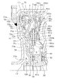
- FIG. 1 is a partial sectional view of a torque converter including a lockup device according to an embodiment of the present invention.
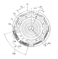
- the front view of the said lockup apparatus which looked at the 1st and 4th torsion spring from the transmission side.
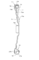
- the front view of the said lockup apparatus which looked at the 2nd and 3rd torsion spring from the transmission side.
- FIG. 1 is a partial sectional view of a torque converter 1 in which a lockup device according to an embodiment of the present invention is employed.
- An engine (not shown) is arranged on the left side of FIG. 1, and a transmission (not shown) is arranged on the right side of the figure.
- OO shown in FIG. 1 is a rotation axis of the torque converter and the lockup device.
- FIG. 2 is an enlarged cross-sectional view of the lockup device.
- 3 and 6 are front partial views of the lockup device.
- 4, 5 and 7 are cross-sectional views of the lockup device.
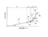
- FIG. 8 is a diagram showing multi-stage torsional characteristics.
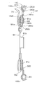
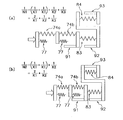
- FIG. 9 is a model diagram when each coil spring is operated at each stage of torsional characteristics.
- the torque converter 1 is mainly composed of a flexible plate (not shown) and a torque converter body 5.
- the flexible plate is made of a thin disk-shaped member, and is a member for transmitting torque and absorbing bending vibration transmitted from the crankshaft to the torque converter body 5. Therefore, the flexible plate has sufficient rigidity for torque transmission in the rotational direction, but has low rigidity in the bending direction.
- the torque converter main body 5 includes a front cover 11, a torus-shaped fluid working chamber 6 including three kinds of impellers (impeller 21, turbine 22, stator 23), and a lockup device 7.
- the front cover 11 is a disk-shaped member and is disposed in the vicinity of the flexible plate.
- a center boss 16 is provided at the inner peripheral end of the front cover 11.
- the center boss 16 is a cylindrical member extending in the axial direction, and is inserted into the center hole of the crankshaft.
- the inner peripheral portion of the flexible plate is fixed to the tip surface of the crankshaft by a plurality of bolts (not shown).
- a plurality of nuts 12 are fixed to the outer peripheral side of the front cover 11 at equal intervals in the circumferential direction.
- Bolts (not shown) screwed into the nut 12 fix the outer peripheral portion of the flexible plate to the front cover 11.
- An outer peripheral cylindrical portion 11 a extending toward the axial transmission side is formed on the outer peripheral portion of the front cover 11.
- the outer peripheral edge of the impeller shell 26 of the impeller 21 is fixed to the distal end of the outer peripheral cylindrical portion 11a by welding.
- the front cover 11 and the impeller 21 form a fluid chamber filled with hydraulic oil.
- the impeller 21 mainly includes an impeller shell 26, a plurality of impeller blades 27 fixed inside the impeller shell 26, and an impeller hub 28 fixed to the inner peripheral portion of the impeller shell 26.
- the turbine 22 is disposed in the fluid chamber so as to face the impeller 21 in the axial direction.
- the turbine 22 mainly includes a turbine shell 30, a plurality of turbine blades 31 fixed to the impeller side surface, and a turbine hub 32 fixed to the inner peripheral edge of the turbine shell 30.
- the turbine shell 30 and the turbine hub 32 are fixed by a plurality of rivets 33.
- a spline that engages with the input shaft is formed on the inner peripheral surface of the turbine hub 32. Thereby, the turbine hub 32 rotates integrally with the input shaft.
- the stator 23 is a mechanism for rectifying the flow of hydraulic oil that returns from the turbine 22 to the impeller 21.
- the stator 23 is a member integrally manufactured by casting with resin, aluminum alloy or the like.
- the stator 23 is disposed between the inner periphery of the impeller 21 and the inner periphery of the turbine 22.
- the stator 23 mainly includes an annular stator shell 35 and a plurality of stator blades 36 provided on the outer peripheral surface of the shell 35.
- the stator shell 35 is supported by a cylindrical fixed shaft (not shown) via a one-way clutch 37.
- the fixed shaft extends between the outer peripheral surface of the input shaft and the inner peripheral surface of the impeller hub 28.
- the torus-shaped fluid working chamber 6 is formed in the fluid chamber by the shells 26, 30, and 35 of the impellers 21, 22, and 23 described above.
- An annular space 9 is secured between the front cover 11 and the fluid working chamber 6 in the fluid chamber.
- the one-way clutch 37 shown in FIG. 1 has a structure using a ratchet, but may have a structure using a roller or a sprag.
- the first port 17 communicates an oil passage provided in the input shaft, a first hydraulic chamber A (described later), and a space between the turbine 22 and the front cover 11.
- a first thrust bearing 42 is disposed between the turbine hub 32 and the inner peripheral portion of the stator 23 (specifically, the one-way clutch 37).
- a second port 18 through which hydraulic oil can communicate is formed on both sides in the radial direction. That is, the second port 18 makes the fluid passage between the input shaft and the fixed shaft and the fluid working chamber 6 communicate with each other.
- a second thrust bearing 43 is disposed between the stator 23 (specifically, the shell 35) and the impeller 21 (specifically, the impeller hub 28) in the axial direction.
- a third port 19 is formed on both sides in the radial direction, through which hydraulic oil can communicate. That is, the third port 19 communicates the oil passage between the fixed shaft and the impeller hub 28 and the fluid working chamber 6.
- Each oil passage is connected to a hydraulic circuit (not shown), and hydraulic oil can be supplied to and discharged from the first to third ports 17 to 19 independently.
- the lockup device 7 is disposed in a space 9 between the turbine 22 and the front cover 11 and is a mechanism for mechanically connecting the two as required. .
- the lockup device 7 is disposed in a space between the front cover 11 and the turbine 22 in the axial direction.
- the lock-up device 7 has a disk shape as a whole, and divides the space 9 substantially in the axial direction.
- a space between the front cover 11 and the lockup device 7 is a first hydraulic chamber A
- a space between the lockup device 7 and the turbine 22 is a second hydraulic chamber B.
- the lock-up device 7 has a function of a clutch and an elastic coupling mechanism.
- the lockup device 7 includes a first elastic coupling mechanism 70 and a second elastic coupling mechanism 80.
- the first elastic connection mechanism 70 and the second elastic connection mechanism 80 are connected in series.
- the first elastic coupling mechanism 70 mainly includes a piston 71, a first drive plate 72, a first driven plate 73, a first torsion spring 74, and a fourth torsion spring. 77 and a spring holder 75.
- the piston 71 is a member for engaging / disengaging the clutch.
- the piston 71 functions as an input member in the lockup device 7 as an elastic coupling mechanism.
- the piston 71 has a disk shape in which a central hole is formed.
- the piston 71 extends over the entire radius in the space 9.
- On the inner peripheral edge of the piston 71 an inner peripheral cylindrical portion 71b extending toward the axial engine side is formed.
- the inner peripheral cylindrical portion 71b is supported by the engine-side outer peripheral surface of the turbine hub 32 so as to be movable in the rotational direction and the axial direction. Note that movement of the piston 71 toward the transmission side in the axial direction is restricted by contacting the hub flange 81 on the transmission side.
- annular seal ring 32b that contacts the inner peripheral surface of the inner peripheral cylindrical portion 71b is provided on the outer peripheral surface of the turbine hub 32 on the engine side.
- an axial seal is provided at the inner peripheral edge of the piston 71.
- a friction coupling portion 71 c is formed on the outer peripheral side of the piston 71.
- the friction coupling portion 71c is an annular portion having a predetermined length in the radial direction, and has a planar shape in which both axial surfaces are surfaces perpendicular to the axial direction.
- An annular friction facing 76 is stretched on the engine side of the friction coupling portion 71c.
- the clutch of the lockup device 7 is configured by the piston 71 and the flat friction surface of the front cover 11.
- a cylindrical portion or the like extending in the axial direction is not formed on the outer peripheral edge of the piston 71.
- the first drive plate 72 is disposed on the axial transmission side of the outer peripheral portion of the piston 71.
- the first drive plate 72 is an annular member made of sheet metal.
- the first drive plate 72 includes a fixed portion 72a, a first torque transmitting portion 72b, and a first engaging portion 72c.
- the fixing portion 72a is fixed to the piston 71 by a plurality of rivets 71d in a state where the fixing portion 72a is in contact with the axial transmission side surface of the piston 71.
- the plurality of first engaging portions 72c extend from the fixed portion 72a to the outer peripheral side. More specifically, the first engaging portion 72c is formed on the axial transmission side on the outer peripheral side of the fixed portion 72a.
- the first engaging portion 72c is a portion that protrudes toward the axial transmission side from the other portions.
- the first torque transmitting portion 72b extends outward from the fixed portion 72a.
- the first torque transmitting portion 72b is smoothly curved so as to be convex toward the axial engine side from the inside toward the outside in the radial direction, and then smoothly curved so as to be convex toward the axial transmission side. Then, it is smoothly curved so as to be convex toward the axial engine side, and finally extends toward the axial transmission side.
- first spring accommodating portions 72d are formed (see FIG. 3). In this embodiment, the first spring accommodating portion 72d is formed at four locations.
- a first torsion spring 74 is accommodated in the first spring accommodating portion 72d.
- the first torsion spring 74 is a pair of torsion springs 74a and 74b.
- Each torsion spring 74a, 74b is a spring extending in the circumferential direction.
- the first torsion spring 74 is a member for elastically connecting the piston 71 as the input member and the first driven plate 73 in the rotational direction.
- a first torsion spring 74 composed of a pair of torsion springs 74a and 74b is arranged so as to act in series in the rotational direction. ing.
- Each of the pair of torsion springs 74a and 74b is formed to have the same torsional rigidity.
- a total of four sets of first torsion springs 74 that is, a total of eight torsion springs 74a and 74b are used in total.
- Each of the eight torsion springs 74a and 74b is formed to have the same free length.
- the fourth torsion spring 77 is an inner periphery of the first torsion spring 74, that is, an inner periphery of each of the pair of torsion springs 74a and 74b disposed in each first spring accommodating portion 72d. Is arranged in the section. Specifically, the fourth torsion spring 77 is formed so that the free length is shorter than the free length of each of the torsion springs 74 a and 74 b constituting the first torsion spring 74. The fourth torsion spring 77 is disposed so as to be movable in the rotation direction on the inner peripheral portions of the torsion springs 74a and 74b. Here, a total of four fourth torsion springs 77 are used. Each of the eight fourth torsion springs 77 is formed to have the same free length.
- each first spring accommodating portion 72d the sign of the torsion spring on the rotation direction R1 side is “74a”, and the sign of the torsion spring on the rotation direction R2 side is “74b”. Yes.
- a set of torsion springs composed of the first torsion spring 74 and the fourth torsion spring 77 act in parallel in the rotational direction. More specifically, a set of torsion springs composed of a torsion spring 74a and a fourth torsion spring 77 act in parallel in the rotational direction. Similarly, a set of torsion springs composed of a torsion spring 74b and a fourth torsion spring 77 acts in parallel in the rotational direction. These torsion springs 74a and 74b act in series in the rotational direction.
- the first driven plate 73 is a member for transmitting the torque from the first torsion spring 74 to the hub flange 81.
- the first driven plate 73 is mainly composed of a first attachment portion 73a, a plurality of first claws 73b, and a connecting portion 73c that connects the first attachment portion 73a and the plurality of first claws 73b. Yes.
- the first attachment portion 73a is fixed to the hub flange 81 by, for example, rivets 34.
- the plurality of first claws 73b are bent toward the axial engine side from the outer peripheral edge of the connecting portion 73c and extend toward the axial engine side.
- the first claw 73b is disposed to face the first torque transmitting portion 72b of the first drive plate 72. Specifically, the first claw 73b is inserted from the axial transmission side into the first torque transmitting portion 72b that is curved so as to protrude toward the axial engine side. In this state, the first pawl 73b is in contact with both ends in the rotational direction of the first torsion spring 74, that is, the pair of one torsion springs 74a and 74b disposed in each first spring accommodating portion 72d.
- a first stopper portion 73d is formed in the connecting portion 73c.
- the first stopper portion 73d is a portion curved toward the engine side on the outer peripheral side of the connecting portion 73c.
- the first stopper portion 73d is disposed between the first engaging portions 72c adjacent in the circumferential direction in the first drive plate 72.
- the first engaging portion 72 c of the first drive plate 72 and the first stopper portion 73 d of the first driven plate 73 shown here function as the first compression restricting means 91.
- the first compression restricting means 91 includes the first engaging portion 72 c of the first drive plate 72 and the first stopper portion 73 d of the first driven plate 73.
- the spring holder 75 is a support member for supporting the first torsion spring 74.
- the spring holder 75 is a member for supporting the first torsion spring 74 in the radial direction.
- the spring holder 75 is disposed so as to be rotatable relative to the piston 71 and the first driven plate 73. Further, the spring holder 75 is disposed so as to be rotatable relative to the first drive plate 72 and the first driven plate 73.
- the spring holder 75 mainly has a support portion 175 and an engaging portion 275.
- the support part 175 is a part that supports the first torsion spring 74.
- the support portion 175 is a portion that supports the first torsion spring 74 that moves radially outward by centrifugal force.
- the engaging portion 275 is a portion that engages with the pair of torsion springs 74 a and 74 b constituting the first torsion spring 74 in the rotational direction.
- the engaging part 275 is formed integrally with the support part 175.
- the spring holder 75 functions as an intermediate float body.
- torque is transmitted from the first torsion spring 74, that is, the pair of torsion springs 74 a and 74 b, to the spring holder 75 via the engaging portion 275.
- the spring holder 75 receives torque transmission not only from the first torsion spring 74 but also from the fourth torsion spring 77.
- the second elastic coupling mechanism 80 mainly includes a hub flange 81, a second drive plate 82, a second torsion spring 83, a third torsion spring 84, The second driven plate 85 is configured.
- the hub flange 81 has a disk shape in which a center hole is formed.
- an inner peripheral cylindrical portion 81b extending toward the axial transmission side is formed.
- the inner peripheral tubular portion 81b of the hub flange 81 is supported by the engine outer peripheral surface of the turbine hub 32 so as to be movable in the rotational direction.
- the inner peripheral cylindrical portion 81 b of the hub flange 81 is sandwiched between the piston 71 and the turbine hub 32.
- the third thrust bearing 44 is disposed between the hub flange 81 and the turbine hub 32.
- the inner peripheral side tubular portion 81 b of the hub flange 81 is sandwiched between the piston 71 and the turbine hub 32 via the third thrust bearing 44.
- a second torque transmission portion 81 a is formed on the outer peripheral side of the hub flange 81.
- the second torque transmission portion 81a is disposed between the second torsion springs 83 adjacent in the circumferential direction. Further, the second torque transmission portion 81 a is in contact with both ends of the second torsion spring 83 in the rotational direction.
- the second torque transmission portion 81a is disposed between a holding plate 182 that constitutes a second drive plate 82, which will be described later, and the torque transmission plate 282.
- a second engagement portion 181a is formed in the second torque transmission portion 81a. The second engagement portion 181a is provided between the rotation directions of the adjacent second torque transmission portions 81a.
- the second drive plate 82 includes a holding plate 182 and a torque transmission plate 282.
- the holding plate 182 is an annular member and is a metal member.
- the holding plate 182 has a holding plate main body 182a, a second spring accommodating portion 182b, and a third spring accommodating portion 182c.
- the second spring accommodating portion 182 b is a portion that accommodates the second torsion spring 83.
- the second torsion spring 83 is disposed and accommodated between the second spring accommodating portion 182b and a fourth spring accommodating portion 282b of the torque transmission plate 282 described later.
- the plurality of second spring accommodating portions 182b are formed on the inner peripheral side of the holding plate body 182a.
- Each of the plurality of second spring accommodating portions 182b is formed in the holding plate body 182a with a predetermined interval in the rotation direction.
- the third spring accommodating portion 182 c is a portion that accommodates the third torsion spring 84.
- the third spring accommodating portion 182c is formed on the outer peripheral portion of the holding plate body 182a. Specifically, the third spring accommodating portion 182 c supports the outer peripheral side of the third torsion spring 84. In other words, the third spring accommodating portion 182c supports the third torsion spring 84 in the radial direction. More specifically, the third torsion spring 84 is accommodated in the third spring accommodating portion 182c and a fifth spring accommodating portion 382d of the torque transmission plate 282 described later.
- the torque transmission plate 282 is an annular member and is a metal member.
- the torque transmission plate 282 includes a torque transmission plate main body 282a, a fourth spring accommodating portion 282b, a second stopper portion 282c, a third torque transmission portion 282d, and a third engagement portion 282e.
- the torque transmission plate body 282a is fixed to the holding plate body 182a.
- the torque transmission plate main body 282a is fixed to the holding plate main body 182a with rivets.
- the fourth spring accommodating portion 282b is a portion that accommodates the second torsion spring 83.
- the fourth spring accommodating portion 282b is formed at a position facing the second spring accommodating portion 182b of the holding plate 182. By disposing the second torsion spring 83 between the fourth spring accommodating portion 282b and the second spring accommodating portion 182b of the holding plate 182, the second torsion spring 83 is positioned.
- the plurality of fourth spring accommodating portions 282b are formed on the inner peripheral side of the torque transmission plate main body 282a. Further, each of the plurality of fourth spring accommodating portions 282b is formed in the torque transmission plate main body 282a with a predetermined interval in the rotation direction.
- the second torsion spring 83 is a spring extending in the circumferential direction.
- the second torsion spring 83 is a member for elastically connecting the hub flange 81 and the second drive plate 82 (torque transmission plate 282) in the rotational direction.
- the second spring accommodating portion 182b and the fourth spring accommodating portion 282b are formed on the inner peripheral side from the first spring accommodating portion 72d. That is, the second torsion spring 83 disposed in the second spring accommodating portion 182 b and the fourth spring accommodating portion 282 b is disposed on the radially inner peripheral side from the first torsion spring 74.
- the second torsion spring 83 is disposed between the piston 71 and the fluid working chamber 6 (turbine 22) on the radially inner side of the first torsion spring 83. More specifically, the second torsion spring 83 is disposed between the first driven plate 73 and the fluid working chamber 6 (turbine 22) on the radially inner peripheral side from the first torsion spring 83.
- the second stopper portion 282c is disposed between the second engaging portions 181a adjacent to each other in the rotation direction in the hub flange 81.
- the second engagement portion 181a of the hub flange 81 and the second stopper portion 282c of the torque transmission plate 282 shown here function as the second compression restricting means 92.
- the second compression restricting means 92 includes the second engagement portion 181a of the hub flange 81 and the second stopper portion 282c of the torque transmission plate 282.
- the third torque transmission portion 282d extends radially outward from the outer peripheral side of the fourth spring accommodating portion 282b. More specifically, the third torque transmitting portion 282d is curved so as to protrude in the axial direction from the inner side to the outer side in the radial direction, and then extends toward the axial transmission side. Between the rotation directions of the adjacent third torque transmission portions 282d, a fifth spring accommodating portion 382d is formed. In this embodiment, the fifth spring accommodating portions 382d are formed at eight locations.
- a third torsion spring 84 is accommodated in the fifth spring accommodating portion 382d.
- the third torsion spring 84 is a spring extending in the circumferential direction.
- the third torsion spring 84 is a member for elastically connecting the torque transmission plate 282 and the second driven plate 85 as an output member in the rotation direction.
- the third spring accommodating portion 182c and the fifth spring accommodating portion 382d are formed on the outer peripheral side from the second spring accommodating portion 182b and the fourth spring accommodating portion 282b. That is, the third torsion spring 84 disposed in the third spring housing portion 182 c and the fifth spring housing portion 382 d is disposed on the radially outer peripheral side from the second torsion spring 83.
- the third torsion spring 84 is disposed between the piston 71 and the fluid working chamber 6. Specifically, the third torsion spring 84 is disposed between the first torsion spring 83 and the fluid working chamber 6 (turbine 22) on the radially outer side of the second torsion spring 83.
- the plurality of third engaging portions 282e extend toward the axial transmission side on the outer peripheral side of the fourth spring accommodating portion 282b. More specifically, the third engagement portion 282e is formed on the axial transmission side in the outer peripheral portion of the torque transmission plate body 282a. The third engaging portion 282e is a portion that protrudes toward the axial transmission side from the other portions.
- the second driven plate 85 is a member for transmitting the torque from the third torsion spring 84 to the turbine 22.
- the second driven plate 85 is provided on the outer peripheral side of the turbine shell 30 of the turbine 22.
- the second driven plate 85 mainly includes a second attachment portion 85a, a plurality of second claws 85b, and a third stopper portion 85c.
- the second attachment portion 85a is fixed to the turbine shell 30 by welding, for example.
- the plurality of second claws 85b are bent from the outer peripheral edge of the second attachment portion 85a toward the axial engine side.
- the second claw 85b is disposed to face the third torque transmission portion 282d of the torque transmission plate 282.
- the second claw 85b is inserted from the axial transmission side into the third torque transmitting portion 282d that is curved so as to protrude toward the axial engine side. In this state, the second claw 85b is in contact with both ends in the rotational direction of the third torsion spring 84 disposed in each fifth spring accommodating portion 382d.
- the third stopper portion 85c is formed between the second attachment portion 85a and the second claw 85b.
- the third stopper portion 85c is disposed between the third engagement portions 282e adjacent to each other in the rotational direction in the second drive plate 82 (torque transmission plate 282).
- torque transmission plate 282 the relative rotation between the second drive plate 82 and the second driven plate 85 increases, and when the third stopper portion 85c comes into contact with any third engagement portion 282e in the rotation direction, the third torsion spring 84 Compression, that is, the damper operation is stopped.
- the third engagement portion 282e of the second drive plate 82 and the third stopper portion 85c of the second driven plate 85 shown here function as the third compression restricting means 93.
- the third compression restricting means 93 includes the third engaging portion 282e of the second drive plate 82 and the third stopper portion 85c of the second driven plate 85.
- the members shown here are a first drive plate 72, a first torsion spring 74, a first driven plate 73, a hub flange 81, a second torsion spring 83, a second drive plate 82, a third torsion spring 84, and the like. .
- the torque is transmitted from the second driven plate 85 to the turbine 22. That is, the front cover 11 is mechanically coupled to the turbine 22, and the torque of the front cover 11 is directly output to the input shaft via the turbine 22.
- the first torsion spring 74 moves radially outward due to centrifugal force and slides against the spring holder 75.
- the spring holder 75 is a member that moves in the rotational direction together with the first torsion spring 74, the sliding resistance between both the members 74 and 75 is greatly reduced, and the torsional vibration damping performance is sufficiently exhibited. .
- the lock-up device 7 transmits torque and absorbs and attenuates torsional vibration input from the front cover 11. Specifically, as shown in FIG. 8, when torsional vibration is input from the front cover 11 to the lockup device 7 and a torsion angle ⁇ is generated between the first drive plate 72 and the second driven plate 85, One torsion spring 74 (74a, 74b) is compressed in the rotational direction between the first drive plate 72 and the first driven plate 73. At this time, the spring holder 75 moves in the compression direction of the first torsion spring 74 and rotates relative to the first drive plate 72 and the first driven plate 73.
- first compressed state J1 The state in which the first torsion spring 74, the second torsion spring 83, and the third torsion spring 84 are compressed in this way is referred to as a first compressed state J1 (see FIG. 8).
- the torsional characteristics can be set to multiple stages, that is, four stages.
- the torsional rigidity N1, N2, N3, N4 can be gradually increased without abrupt change.
- the torsional rigidity ratio can be set small by setting the torsional characteristics to four stages.
- the torsional rigidity ratio for example, the ratio of the second torsional rigidity to the first torsional rigidity (N2 / N1), compared to the case where the torsional characteristics are set to two or three stages, and
- the third torsional rigidity (N3 / N2) relative to the second torsional rigidity can be set small.
- the first bending point P1, the second bending point P2, and the fourth bending point P4 are set by the first to third compression restricting means 91, 92, 93.
- the bending points P1, P2, and P4 can be easily controlled, so that multistage torsional characteristics can be easily designed.
- the torsional rigidity can be reliably changed. That is, the torque desired by the designer can be reliably transmitted from the input side to the output side.
- the first torsion spring 74, the second torsion spring 83, and the third torsion spring 84 are arranged in series, so that the torsional rigidity is smaller than the conventional torsional rigidity. Can be set. Thereby, the twist angle of a coil spring can be set to a wider angle.
- the torsional rigidity in the state where the first torsion spring 74, the second torsion spring 83, and the third torsion spring 84 are operating for example, the first stage torsional rigidity is smaller than the conventional torsional rigidity. Can be set. For this reason, the vibration resulting from a coil spring can be suppressed reliably.
- the present lock-up device 7 can achieve a wide-angle and low-rigidity torsional characteristic.
- the second torsion spring 83 is disposed on the radially inner side from the first torsion spring 74 and the third torsion spring 84. That is, the first torsion spring 74 and the third torsion spring 84 are disposed above in the internal space of the torque converter.
- the second torsion spring 83 and the third torsion spring 84 are disposed between the piston 71 and the fluid working chamber 6 of the torque converter. Torque can be transmitted to the fluid working chamber 6, such as the turbine 22, while effectively attenuating the input torque fluctuation.
- the first torsion spring 74 includes a pair of torsion springs, and the pair of torsion springs are arranged in series with each other. For this reason, the torsional rigidity of the first torsion spring 74 can be reduced as compared with the case where the first torsion spring 74 is configured by one torsion spring. Thereby, vibration that may occur when the torsion angle is small, such as vibration when the lockup device 7 operates with the first-stage torsional rigidity, can be reliably suppressed.
- the free length of the fourth torsion spring 77 is shorter than the free length of the first torsion spring 74.
- the fourth torsion spring 77 is disposed on the inner peripheral portion of the first torsion spring 74.
- a transition point (third bending point P3) from one torsional characteristic to the next torsional characteristic can be added to the torsional characteristic.
- the torsion characteristic as the whole system can be formed with a smooth curve. That is, a torsional characteristic with little fluctuation can be formed.
- the first torsion spring 74 and the fourth torsion spring 77 are compressed in parallel. As a result, the torsional rigidity at the fourth stage can be increased, so that the target torque can be easily obtained.
- the present invention can be used for a torque converter lock-up device for transmitting torque and absorbing / damping torsional vibration.
Landscapes
- Engineering & Computer Science (AREA)
- General Engineering & Computer Science (AREA)
- Mechanical Engineering (AREA)
- Physics & Mathematics (AREA)
- Acoustics & Sound (AREA)
- Aviation & Aerospace Engineering (AREA)
- Mechanical Operated Clutches (AREA)
Abstract
Description
従来のロックアップ装置では、捩り特性は線形であるため、この捩り特性を用いて所定のトルク変動を減衰しようとすると、捩り剛性を大きくせざるを得なかった。しかしながら、捩り剛性をあまり大きくしてしまうと、コイルスプリングに起因する振動が発生してしまうおそれがある。
一方で、トルク変動の目標減衰量が大きい場合に、コイルスプリングに起因する振動を抑制する目的で、2段の捩り特性の第1捩り剛性(1段目の捩り剛性)を小さくすると、初期振動は抑制することはできるものの、目標減衰量を確保するために、第2捩り剛性(2段目の捩り剛性)を大きくする必要がある。このため、この場合は、第1捩り剛性に対する第2捩り剛性の比が大きくなってしまい、捩り特性の屈曲点およびこの屈曲点を超えた範囲において、新たな振動(ジャンピング振動)が発生してしまうおそれがある。すなわち、この場合にも、コイルスプリングに起因する振動を抑制しきれないという問題が、発生してしまっていた。
出力回転部材は、入力回転部材に対して相対回転可能である。第1コイルスプリングは、入力回転部材からトルクが伝達される。第2コイルスプリングは、第1コイルスプリングより径方向内周側に配置されている。第2コイルスプリングは、第1コイルスプリングと直列に作用する。第3コイルスプリングは、第2コイルスプリングより径方向外周側に配置されている。第3コイルスプリングは、第2コイルスプリングと直列に作用する。第3コイルスプリングは、出力回転部材へトルクを伝達する。
この場合、例えば、エンジンのトルクが入力回転部材から第1コイルスプリングに入力されると、第1コイルスプリングと、第2コイルスプリングと、第3コイルスプリングとが、圧縮される。すると、各コイルスプリングの捩り剛性に応じて、捩り振動が吸収・減衰される(1段目の捩り特性)。ここで、第1コイルスプリング、第2コイルスプリング、及び第3コイルスプリングのいずれか1つのコイルスプリングを圧縮不能にした場合、圧縮可能なコイルスプリングの捩り剛性に応じて、捩り振動が吸収・減衰される(2段目の捩り特性)。また、第1コイルスプリング、第2コイルスプリング、及び第3コイルスプリングのいずれか2つのコイルスプリングを圧縮不能にした場合、圧縮可能な1つのコイルスプリングの捩り剛性に応じて、捩り振動が吸収・減衰される(3段目の捩り特性)。なお、ここに示した多段の捩り特性は、動作の理解を容易にするための一例であって、発明の要旨を逸脱しない範囲で種々の変更が可能である。
また、本ロックアップ装置では、第1コイルスプリング、第2コイルスプリング、及び第3コイルスプリングを、直列に配置することによって、従来の捩り剛性と比較して、捩り剛性をより小さく設定することができる。これにより、コイルスプリングの捩り角度をより広角に設定することができる。例えば、第1コイルスプリング、第2コイルスプリング、及び第3コイルスプリングが動作している状態の捩り剛性、例えば1段目の捩り剛性を、従来の捩り剛性と比較して、より小さく設定することができるので、コイルスプリングに起因する振動を、確実に抑制することができる。このように、本ロックアップ装置では、広角且つ低剛性の捩り特性を実現することができる。
ここでは、第1コイルスプリングが、一対のコイルスプリングから構成されている。また、この一対のコイルスプリングは、互いに直列に配置されている。このため、第1コイルスプリングが、1つのコイルスプリングから構成される場合と比較して、第1コイルスプリングの捩り剛性を、小さくすることができる。これにより、広角化を図りながら、捩り角度が小さい場合に発生し得る振動を、確実に抑制することができる。
この場合、例えば、エンジンのトルクが入力回転部材から第1コイルスプリングに入力されると、第1から第3のコイルスプリングが圧縮され、各コイルスプリングの捩り剛性に応じて、捩り振動が吸収・減衰される(1段目の捩り特性)。ここで、第2コイルスプリング及び第3コイルスプリングのいずれか一方のコイルスプリングを圧縮不能にした場合、圧縮可能なコイルスプリングの捩り剛性に応じて、捩り振動が吸収・減衰される(2段目の捩り特性)。また、第2コイルスプリング及び第3コイルスプリングのいずれか他方のコイルスプリングを圧縮不能にした場合、第1コイルスプリングの捩り剛性に応じて、捩り振動が吸収・減衰される(3段目の捩り特性)。ここで、第1コイルスプリングがさらに圧縮されると、第1コイルスプリング及び第4コイルスプリングが圧縮され、これらコイルスプリングの捩り剛性に応じて、捩り振動が吸収・減衰される(4段目の捩り特性)。なお、ここに示した多段の捩り特性は、動作の理解を容易にするための一例であって、発明の要旨を逸脱しない範囲で種々の変更が可能である。
ここでは、第3コイルスプリングが、第1コイルスプリングを基準として、軸方向トランスミッション側に配置されている。また、上述したように、第3コイルスプリングは、径方向外周側に配置されている。これにより、第3コイルスプリングは、トルクコンバータの内部空間における、径方向外方の余剰空間を、有効に利用することができる。これにより、上記の断面に配置されるコイルスプリングの本数が増えたとしても、トルクコンバータのサイズを変更することなく、上記のような効果を得ることができる。
ここでは、第2コイルスプリング及び第3コイルスプリングが、入力回転部材と、トルクコンバータの流体作動室との間に、配置されているので、第1コイルスプリングに入力されたトルク変動を、効果的に減衰しながら、トルクを、流体作動室たとえばタービンへと伝達することができる。
ここでは、圧縮規制手段によって、第1コイルスプリング、第2コイルスプリング、及び第3コイルスプリングの少なくともいずれか1つの圧縮が規制される。このため、圧縮不能になったコイルスプリングにおいては、捩り振動を吸収・減衰するためのダンパー動作が、停止する。これにより、屈曲点を容易に制御することができるので、多段の捩り特性を自由に設計することができる。
ここでは、第1コイルスプリング、第2コイルスプリング、及び第3コイルスプリングの少なくともいずれか1つを、線間密着によって圧縮不能にすることによって、屈曲点が制御される。これにより、特別な機構や手段を用意しなくても、屈曲点を制御することができるので、ロックアップ装置を小型化することができる。すなわち、トルクコンバータを小型化することができる。
トルクコンバータ1は、主に、フレキシブルプレート(図示しない)と、トルクコンバータ本体5とから、構成されている。フレキシブルプレートは、円板状の薄い部材からなり、トルクを伝達するとともにクランクシャフトからトルクコンバータ本体5に伝達される曲げ振動を吸収するための部材である。したがって、フレキシブルプレートは、回転方向にはトルク伝達に十分な剛性を有しているが、曲げ方向には剛性が低くなっている。
フロントカバー11は、円板状の部材であり、フレキシブルプレートに近接して配置されている。フロントカバー11の内周端にはセンターボス16が設けられている。センターボス16は、軸方向に延びる円筒形状の部材であり、クランクシャフトの中心孔内に挿入されている。
フロントカバー11の外周部には、軸方向トランスミッション側に延びる外周側筒状部11aが形成されている。この外周側筒状部11aの先端には、インペラー21のインペラーシェル26の外周縁が、溶接によって固定されている。この結果、フロントカバー11とインペラー21とによって、内部に作動油が充填された流体室が形成されている。インペラー21は、主に、インペラーシェル26と、その内側に固定された複数のインペラーブレード27と、インペラーシェル26の内周部に固定されたインペラーハブ28とから、構成されている。
ステータ23は、タービン22からインペラー21に戻る作動油の流れを整流するための機構である。ステータ23は樹脂やアルミ合金等で鋳造により一体に製作された部材である。ステータ23は、インペラー21の内周部とタービン22の内周部と間に、配置されている。ステータ23は、主に、環状のステータシェル35と、シェル35の外周面に設けられた複数のステータブレード36とから、構成されている。ステータシェル35は、ワンウェイクラッチ37を介して、筒状の固定シャフト(図示しない)に支持されている。固定シャフトは、入力シャフトの外周面とインペラーハブ28の内周面との間において、延びている。
また、タービンハブ32とステータ23の内周部(具体的にはワンウェイクラッチ37)との間には、第1スラストベアリング42が配置されている。この第1スラストベアリング42が配置された部分において、半径方向両側に作動油が連通可能な第2ポート18が形成されている。すなわち、第2ポート18は、入力シャフト及び固定シャフトの間の油路と、流体作動室6とを連通させている。
図1から図7に示すように、ロックアップ装置7は、タービン22とフロントカバー11との間の空間9に配置されており、必要に応じて両者を機械的に連結するための機構である。ロックアップ装置7は、フロントカバー11とタービン22との軸方向間の空間に配置されている。ロックアップ装置7は全体が円板状になっており、空間9を概ね軸方向に分割している。ここでは、フロントカバー11とロックアップ装置7との間の空間を第1油圧室Aとし、ロックアップ装置7とタービン22との間の空間を第2油圧室Bとする。
図2-図5に示すように、第1弾性連結機構70は、主に、ピストン71と、第1ドライブプレート72と、第1ドリブンプレート73と、第1トーションスプリング74と、第4トーションスプリング77と、スプリングホルダー75とから、構成されている。
第1トーションスプリング74及び第4トーションスプリング77から構成される一組のトーションスプリングは、回転方向に並列に作用する。より具体的には、トーションスプリング74aと第4トーションスプリング77とから構成される一組のトーションスプリングは、回転方向に並列に作用する。同様に、トーションスプリング74bと第4トーションスプリング77とから構成される一組のトーションスプリングは、回転方向に並列に作用する。そして、これらトーションスプリング74a,74bは、回転方向に直列に作用する。
スプリングホルダー75は、第1トーションスプリング74をサポートするためのサポート部材である。具体的には、スプリングホルダー75は、第1トーションスプリング74を半径方向に支持するための部材である。スプリングホルダー75は、ピストン71及び第1ドリブンプレート73に対して、相対回転可能に配置されている。また、スプリングホルダー75は、第1ドライブプレート72及び第1ドリブンプレート73に対して、相対回転可能に配置されている。
ハブフランジ81は、中心孔が形成された円板形状である。ハブフランジ81の内周縁には、軸方向トランスミッション側に延びる内周側筒状部81bが形成されている。ハブフランジ81の内周側筒状部81bは、タービンハブ32のエンジン側の外周面によって、回転方向に移動可能に支持されている。また、ハブフランジ81の内周側筒状部81bは、ピストン71とタービンハブ32とによって、挟持されている。詳細には、ハブフランジ81とタービンハブ32との間には、第3スラストベアリング44が配置されている。この第3スラストベアリング44を介して、ハブフランジ81の内周側筒状部81bは、ピストン71とタービンハブ32とによって、挟持されている。
トルク伝達プレート本体282aは、保持プレート本体182aに固定されている。例えば、トルク伝達プレート本体282aは、保持プレート本体182aに、リベットにより固定されている。
ここで、図2に示すように、第3ばね収容部182c及び第5ばね収容部382dは、第2ばね収容部182b及び第4ばね収容部282bより外周側に形成されている。すなわち、第3ばね収容部182c及び第5ばね収容部382dに配置される第3トーションスプリング84は、第2トーションスプリング83より、径方向外周側に配置される。また、第3トーションスプリング84は、ピストン71と流体作動室6との間に、配置されている。具体的には、第3トーションスプリング84は、第2トーションスプリング83より径方向外周側において、第1トーションスプリング83と流体作動室6(タービン22)との間に、配置されている。
エンジン始動直後には、第1ポート17及び第3ポート19からトルクコンバータ本体5内に作動油が供給され、第2ポート18から作動油が排出される。第1ポート17から供給された作動油は、第1油圧室Aを外周側に流れ、第2油圧室Bを通過して流体作動室6内に流れ込む。このため、第1油圧室Aと第2油圧室Bとの油圧差によってピストン71は軸方向トランスミッション側に移動する。すなわち、摩擦フェーシング76はフロントカバー11から離れ、ロックアップが解除される。このようにロックアップが解除されている状態では、フロントカバー11とタービン22との間のトルク伝達は、インペラー21とタービン22との間の流体駆動によって行われる。
トルクコンバータ1の速度比が上がり、入力シャフトが一定の回転数に達すると、第1ポート17から第1油圧室Aの作動油が排出される。この結果、第1油圧室Aと第2油圧室Bとの油圧差によって、ピストン71がフロントカバー11側に移動させられ、摩擦フェーシング76がフロントカバー11の平坦な摩擦面に押し付けられる。
なお、以上のように捩り振動が入力されて第1トーションスプリング74が圧縮を繰り返す際には、遠心力によって第1トーションスプリング74は半径方向外側に移動し、スプリングホルダー75に対して摺動している。しかしながら、スプリングホルダー75は、第1トーションスプリング74とともに回転方向に移動する部材であるため、両部材74,75間での摺動抵抗は大幅に低減し、捩り振動減衰性能は十分に発揮される。
以上に述べたロックアップした状態(連結状態)において、ロックアップ装置7は、トルクを伝達するとともにフロントカバー11から入力される捩り振動を吸収・減衰する。具体的には、図8に示すように、フロントカバー11からロックアップ装置7に捩り振動が入力され、第1ドライブプレート72と第2ドリブンプレート85との間に捩り角度θが生じると、第1トーションスプリング74(74a,74b)が、第1ドライブプレート72と第1ドリブンプレート73との間で回転方向に圧縮される。このとき、スプリングホルダー75は、第1トーションスプリング74の圧縮方向に移動し、第1ドライブプレート72及び第1ドリブンプレート73に対して相対回転する。
上記のように、第1から第4のトーションスプリング74,83,84,77が動作する場合の捩り特性を、以下に説明する。
図8及び図9に示すように、第1の圧縮状態J1では、直列に配置された第1から第3トーションスプリング74(74a,74b),83,84の捩り剛性N1(=1/[2/K1+1/K2+1/K3])が、系の捩り剛性N1として設定される(図9(a)を参照)。すると、この系の捩り剛性N1に基づいて、捩り特性の第1勾配D1が、設定される。次に、第2の圧縮状態J2では、2つの第1及び第2トーションスプリング74(74a,74b),83の捩り剛性N2(=1/[2/K1+1/K2])が、系の捩り剛性N2として設定される(図9(b)を参照)。すると、この系の捩り剛性N2に基づいて、捩り特性の第2勾配D2が、設定される。
[捩り振動減衰特性の有利な効果]
本ロックアップ装置7では、捩り特性を、多段すなわち4段に設定することができる。このように捩り特性を4段に設定することにより、捩り剛性N1,N2,N3,N4を、急激に変化させることなく、徐々に大きくすることができる。詳細には、本ロックアップ装置7では、捩り特性を4段に設定することにより、捩り剛性の比を小さく設定することができる。例えば、本ロックアップ装置7では、捩り特性を2段や3段に設定する場合と比較して、捩り剛性の比、例えば第1捩り剛性に対する第2捩り剛性の比(N2/N1)、及び第2捩り剛性に対する第3捩り剛性(N3/N2)を小さく設定することができる。これにより、捩り特性における各屈曲点を越えるときに発生する振動を、抑制することができる。
また、本ロックアップ装置7では、第1トーションスプリング74が、一対のトーションスプリングから構成され、この一対のトーションスプリングは、互いに直列に配置されている。このため、第1トーションスプリング74が、1つのトーションスプリングから構成される場合と比較して、第1トーションスプリング74の捩り剛性を、小さくすることができる。これにより、捩り角度が小さい場合に発生し得る振動、例えばロックアップ装置7が1段目の捩り剛性で動作する場合の振動を、確実に抑制することができる。
(a)前記実施形態では、第1から第3圧縮規制手段91,92,93によって、第1から第3トーションスプリング84の圧縮を規制する場合の例を示したが、各トーションスプリングを線間密着させることによって、第1から第3トーションスプリング74,83,84の少なくともいずれか1つを圧縮不能にしてもよい。例えば、あるトーションスプリングに対しては圧縮規制手段91,92,93を用い、他のトーションスプリングについては線間密着させることによって、トーションスプリングを圧縮不能にしてもよい。
6 流体作動室
7 ロックアップ装置
71 ピストン(入力回転部材)
74,74a,74b 第1トーションスプリング(第1コイルスプリング)
77 第4トーションスプリング(第4コイルスプリング)
83 第2トーションスプリング(第2コイルスプリング)
84 第3トーションスプリング(第3コイルスプリング)
85 第2ドリブンプレート(出力回転部材)
91,92,93 圧縮規制手段
D1 捩り特性の第1勾配
D2 捩り特性の第2勾配
D3 捩り特性の第3勾配
D4 捩り特性の第4勾配
Claims (7)
- トルクを伝達するとともに捩り振動を吸収・減衰するためのトルクコンバータのロックアップ装置であって、
入力回転部材と、
前記入力回転部材に対して相対回転可能な出力回転部材と、
前記入力回転部材からトルクが伝達される第1コイルスプリングと、
前記第1コイルスプリングより径方向内周側に配置され前記第1コイルスプリングと直列に作用する第2コイルスプリングと、
前記第2コイルスプリングより径方向外周側に配置され前記第2コイルスプリングと直列に作用し、前記出力回転部材へトルクを伝達する第3コイルスプリングと、
を備えるロックアップ装置。 - 前記第1コイルスプリングは、一対のコイルスプリングであり、一対の前記コイルスプリングは、円周方向に直列に配置されている、
請求項1に記載のロックアップ装置。 - 自由長が前記第1コイルスプリングの自由長より短く、前記第1コイルスプリングの内周部に配置される第4コイルスプリング、
をさらに備える請求項1又は2に記載のロックアップ装置。 - 前記第3コイルスプリングは、前記第1コイルスプリングを基準として、軸方向トランスミッション側に配置されている、
請求項1から3のいずれかに記載のロックアップ装置。 - 前記第2コイルスプリング及び第3コイルスプリングは、前記入力回転部材と、前記トルクコンバータの流体作動室との間に、配置されている、
請求項1から4のいずれかに記載のロックアップ装置。 - 前記第1コイルスプリング、前記第2コイルスプリング、及び前記第3コイルスプリングの少なくともいずれか1つの圧縮を規制するための圧縮規制手段、
をさらに備える請求項1から5のいずれかに記載のロックアップ装置。 - 前記第1コイルスプリング、前記第2コイルスプリング、及び前記第3コイルスプリングの少なくともいずれか1つを線間密着させることによって、前記少なくともいずれか1つのコイルスプリングを、圧縮不能にする、
請求項1から6のいずれかに記載のロックアップ装置。
Priority Applications (3)
| Application Number | Priority Date | Filing Date | Title |
|---|---|---|---|
| CN2012800113121A CN103403397A (zh) | 2011-04-14 | 2012-02-03 | 扭矩转换器的锁定装置 |
| DE112012001668.8T DE112012001668T5 (de) | 2011-04-14 | 2012-02-03 | Überbrückungsvorrichtung für einen Drehmomentwandler |
| US14/005,875 US8978853B2 (en) | 2011-04-14 | 2012-02-03 | Lock-up device for torque converter |
Applications Claiming Priority (2)
| Application Number | Priority Date | Filing Date | Title |
|---|---|---|---|
| JP2011089731A JP5315377B2 (ja) | 2011-04-14 | 2011-04-14 | トルクコンバータ用のロックアップ装置 |
| JP2011-089731 | 2011-04-14 |
Publications (1)
| Publication Number | Publication Date |
|---|---|
| WO2012140938A1 true WO2012140938A1 (ja) | 2012-10-18 |
Family
ID=47009124
Family Applications (1)
| Application Number | Title | Priority Date | Filing Date |
|---|---|---|---|
| PCT/JP2012/052515 Ceased WO2012140938A1 (ja) | 2011-04-14 | 2012-02-03 | トルクコンバータ用のロックアップ装置 |
Country Status (5)
| Country | Link |
|---|---|
| US (1) | US8978853B2 (ja) |
| JP (1) | JP5315377B2 (ja) |
| CN (1) | CN103403397A (ja) |
| DE (1) | DE112012001668T5 (ja) |
| WO (1) | WO2012140938A1 (ja) |
Cited By (1)
| Publication number | Priority date | Publication date | Assignee | Title |
|---|---|---|---|---|
| US10036459B2 (en) | 2013-05-16 | 2018-07-31 | Exedy Corporation | Lock-up device for torque converter |
Families Citing this family (20)
| Publication number | Priority date | Publication date | Assignee | Title |
|---|---|---|---|---|
| JP5632444B2 (ja) * | 2012-11-27 | 2014-11-26 | 株式会社エクセディ | ロックアップ装置 |
| JP5555784B1 (ja) * | 2013-02-26 | 2014-07-23 | 株式会社エクセディ | ダイナミックダンパ装置 |
| JP5684846B2 (ja) | 2013-03-21 | 2015-03-18 | 株式会社エクセディ | トルクコンバータのロックアップ装置 |
| JP5688113B2 (ja) | 2013-04-09 | 2015-03-25 | 株式会社エクセディ | トルクコンバータ用のロックアップ装置 |
| JP5734365B2 (ja) | 2013-06-04 | 2015-06-17 | 株式会社エクセディ | トルクコンバータのロックアップ装置 |
| JP5685304B2 (ja) | 2013-06-04 | 2015-03-18 | 株式会社エクセディ | トルクコンバータのロックアップ装置 |
| JP5878893B2 (ja) | 2013-07-11 | 2016-03-08 | 株式会社エクセディ | トルクコンバータのロックアップ装置 |
| JP6252458B2 (ja) * | 2014-04-30 | 2017-12-27 | アイシン・エィ・ダブリュ株式会社 | ダンパ装置 |
| JP5828030B1 (ja) * | 2014-10-29 | 2015-12-02 | 株式会社エクセディ | トルクコンバータのロックアップ装置 |
| WO2017159808A1 (ja) * | 2016-03-16 | 2017-09-21 | アイシン・エィ・ダブリュ株式会社 | ダンパ装置および発進装置 |
| JP6668124B2 (ja) * | 2016-03-18 | 2020-03-18 | 株式会社エクセディ | トルクコンバータのロックアップ装置 |
| KR101803952B1 (ko) * | 2016-05-25 | 2017-12-01 | 한국파워트레인 주식회사 | 차량용 토크 컨버터 |
| US10030754B2 (en) * | 2016-08-01 | 2018-07-24 | GM Global Technology Operations LLC | Torque converter with fluid coupling damper |
| US10197105B2 (en) * | 2017-02-18 | 2019-02-05 | Schaeffler Technologies AG & Co. KG | Motor vehicle clutch assembly including stop for limiting liftoff of a clutch plate assembly |
| US10612636B2 (en) * | 2018-03-01 | 2020-04-07 | Martin W. ChANCE | Hydraulic torque converter |
| KR102289993B1 (ko) | 2020-01-14 | 2021-08-13 | 현대트랜시스 주식회사 | 차량용 토션 댐퍼 |
| JP7477370B2 (ja) * | 2020-06-01 | 2024-05-01 | 株式会社エクセディ | ロックアップ装置 |
| JP7451307B2 (ja) * | 2020-06-01 | 2024-03-18 | 株式会社エクセディ | ロックアップ装置 |
| KR102351608B1 (ko) * | 2020-06-19 | 2022-01-13 | 현대트랜시스 주식회사 | 차량용 토셔널 댐퍼 |
| US11725717B1 (en) * | 2022-07-28 | 2023-08-15 | Schaeffler Technologies AG & Co. KG | Torque converter damper assembly |
Citations (6)
| Publication number | Priority date | Publication date | Assignee | Title |
|---|---|---|---|---|
| JPH11173382A (ja) * | 1997-12-12 | 1999-06-29 | Exedy Corp | ダンパーディスク組立体 |
| JP2006029553A (ja) * | 2004-07-21 | 2006-02-02 | Exedy Corp | 流体式トルク伝達装置用ロックアップ装置 |
| JP2009156270A (ja) * | 2007-12-25 | 2009-07-16 | Aisin Aw Industries Co Ltd | トルクコンバータのロックアップダンパ装置 |
| JP2009243599A (ja) * | 2008-03-31 | 2009-10-22 | Aisin Aw Co Ltd | ダンパ装置 |
| WO2010043194A1 (de) * | 2008-10-16 | 2010-04-22 | Luk Lamellen Und Kupplungsbau Beteiligungs Kg | Hydrodynamischer drehmomentwandler |
| JP2011002014A (ja) * | 2009-06-18 | 2011-01-06 | Aisin Aw Industries Co Ltd | ダンパ装置 |
Family Cites Families (7)
| Publication number | Priority date | Publication date | Assignee | Title |
|---|---|---|---|---|
| JPH0326341Y2 (ja) * | 1986-10-15 | 1991-06-07 | ||
| JP3982845B2 (ja) * | 1995-06-09 | 2007-09-26 | ヴァレオユニシアトランスミッション株式会社 | 捩り振動低減装置 |
| JP4999438B2 (ja) | 2006-12-04 | 2012-08-15 | 株式会社エクセディ | ロックアップ装置およびそれを備えた流体式トルク伝達装置 |
| JP5882299B2 (ja) * | 2010-04-12 | 2016-03-09 | シェフラー テクノロジーズ アー・ゲー ウント コー. カー・ゲーSchaeffler Technologies AG & Co. KG | タービン質量アブソーバを備えるトルクコンバータ |
| JP5556551B2 (ja) * | 2010-09-30 | 2014-07-23 | アイシン・エィ・ダブリュ株式会社 | 流体伝動装置 |
| JP5556546B2 (ja) * | 2010-09-30 | 2014-07-23 | アイシン・エィ・ダブリュ株式会社 | 流体伝動装置 |
| JP5477249B2 (ja) * | 2010-09-30 | 2014-04-23 | アイシン・エィ・ダブリュ株式会社 | 発進装置 |
-
2011
- 2011-04-14 JP JP2011089731A patent/JP5315377B2/ja active Active
-
2012
- 2012-02-03 DE DE112012001668.8T patent/DE112012001668T5/de not_active Withdrawn
- 2012-02-03 US US14/005,875 patent/US8978853B2/en not_active Expired - Fee Related
- 2012-02-03 CN CN2012800113121A patent/CN103403397A/zh active Pending
- 2012-02-03 WO PCT/JP2012/052515 patent/WO2012140938A1/ja not_active Ceased
Patent Citations (6)
| Publication number | Priority date | Publication date | Assignee | Title |
|---|---|---|---|---|
| JPH11173382A (ja) * | 1997-12-12 | 1999-06-29 | Exedy Corp | ダンパーディスク組立体 |
| JP2006029553A (ja) * | 2004-07-21 | 2006-02-02 | Exedy Corp | 流体式トルク伝達装置用ロックアップ装置 |
| JP2009156270A (ja) * | 2007-12-25 | 2009-07-16 | Aisin Aw Industries Co Ltd | トルクコンバータのロックアップダンパ装置 |
| JP2009243599A (ja) * | 2008-03-31 | 2009-10-22 | Aisin Aw Co Ltd | ダンパ装置 |
| WO2010043194A1 (de) * | 2008-10-16 | 2010-04-22 | Luk Lamellen Und Kupplungsbau Beteiligungs Kg | Hydrodynamischer drehmomentwandler |
| JP2011002014A (ja) * | 2009-06-18 | 2011-01-06 | Aisin Aw Industries Co Ltd | ダンパ装置 |
Cited By (1)
| Publication number | Priority date | Publication date | Assignee | Title |
|---|---|---|---|---|
| US10036459B2 (en) | 2013-05-16 | 2018-07-31 | Exedy Corporation | Lock-up device for torque converter |
Also Published As
| Publication number | Publication date |
|---|---|
| US8978853B2 (en) | 2015-03-17 |
| CN103403397A (zh) | 2013-11-20 |
| US20140008174A1 (en) | 2014-01-09 |
| JP5315377B2 (ja) | 2013-10-16 |
| DE112012001668T5 (de) | 2014-01-30 |
| JP2012219999A (ja) | 2012-11-12 |
Similar Documents
| Publication | Publication Date | Title |
|---|---|---|
| JP5315377B2 (ja) | トルクコンバータ用のロックアップ装置 | |
| JP5952432B2 (ja) | ダンパ装置および発進装置 | |
| JP6044725B2 (ja) | ダンパ装置および発進装置 | |
| KR101660478B1 (ko) | 토크 컨버터의 록업 장치 | |
| JP4755277B2 (ja) | トルクコンバータ用ロックアップ装置 | |
| JP5531728B2 (ja) | 流体伝動装置 | |
| JP4773553B2 (ja) | トルクコンバータ用ロックアップ装置 | |
| JP5589883B2 (ja) | ダンパ装置 | |
| JP6090466B2 (ja) | ダンパ装置および発進装置 | |
| JP2011122622A (ja) | トルクコンバータ用ロックアップ装置 | |
| JP4949503B2 (ja) | トルクコンバータ用のロックアップ装置 | |
| JP5632444B2 (ja) | ロックアップ装置 | |
| JP4926228B2 (ja) | トルクコンバータの動力伝達装置 | |
| JP4791582B2 (ja) | トルクコンバータ用のロックアップ装置 | |
| JP2011252584A (ja) | トルクコンバータ用のロックアップ装置 | |
| JP5106555B2 (ja) | トルクコンバータ用のロックアップ装置 | |
| JP2010014206A (ja) | 捩り振動低減装置 | |
| JP2002070949A (ja) | 弾性連結機構及びトルクコンバータのロックアップ装置 | |
| JP2006177418A (ja) | 流体式トルク伝達装置のロックアップ装置 | |
| JP2011085236A (ja) | トルクコンバータ用のロックアップ装置 |
Legal Events
| Date | Code | Title | Description |
|---|---|---|---|
| 121 | Ep: the epo has been informed by wipo that ep was designated in this application |
Ref document number: 12770906 Country of ref document: EP Kind code of ref document: A1 |
|
| WWE | Wipo information: entry into national phase |
Ref document number: 14005875 Country of ref document: US |
|
| WWE | Wipo information: entry into national phase |
Ref document number: 112012001668 Country of ref document: DE Ref document number: 1120120016688 Country of ref document: DE |
|
| 122 | Ep: pct application non-entry in european phase |
Ref document number: 12770906 Country of ref document: EP Kind code of ref document: A1 |