WO2012140753A1 - 内燃機関の燃料噴射制御システム - Google Patents
内燃機関の燃料噴射制御システム Download PDFInfo
- Publication number
- WO2012140753A1 WO2012140753A1 PCT/JP2011/059196 JP2011059196W WO2012140753A1 WO 2012140753 A1 WO2012140753 A1 WO 2012140753A1 JP 2011059196 W JP2011059196 W JP 2011059196W WO 2012140753 A1 WO2012140753 A1 WO 2012140753A1
- Authority
- WO
- WIPO (PCT)
- Prior art keywords
- internal combustion
- combustion engine
- fuel
- poisoning
- exhaust
- Prior art date
- Legal status (The legal status is an assumption and is not a legal conclusion. Google has not performed a legal analysis and makes no representation as to the accuracy of the status listed.)
- Ceased
Links
Images

Classifications
-
- F—MECHANICAL ENGINEERING; LIGHTING; HEATING; WEAPONS; BLASTING
- F01—MACHINES OR ENGINES IN GENERAL; ENGINE PLANTS IN GENERAL; STEAM ENGINES
- F01N—GAS-FLOW SILENCERS OR EXHAUST APPARATUS FOR MACHINES OR ENGINES IN GENERAL; GAS-FLOW SILENCERS OR EXHAUST APPARATUS FOR INTERNAL-COMBUSTION ENGINES
- F01N3/00—Exhaust or silencing apparatus having means for purifying, rendering innocuous, or otherwise treating exhaust
- F01N3/08—Exhaust or silencing apparatus having means for purifying, rendering innocuous, or otherwise treating exhaust for rendering innocuous
- F01N3/10—Exhaust or silencing apparatus having means for purifying, rendering innocuous, or otherwise treating exhaust for rendering innocuous by thermal or catalytic conversion of noxious components of exhaust
- F01N3/18—Exhaust or silencing apparatus having means for purifying, rendering innocuous, or otherwise treating exhaust for rendering innocuous by thermal or catalytic conversion of noxious components of exhaust characterised by methods of operation; Control
-
- F—MECHANICAL ENGINEERING; LIGHTING; HEATING; WEAPONS; BLASTING
- F02—COMBUSTION ENGINES; HOT-GAS OR COMBUSTION-PRODUCT ENGINE PLANTS
- F02D—CONTROLLING COMBUSTION ENGINES
- F02D19/00—Controlling engines characterised by their use of non-liquid fuels, pluralities of fuels, or non-fuel substances added to the combustible mixtures
- F02D19/06—Controlling engines characterised by their use of non-liquid fuels, pluralities of fuels, or non-fuel substances added to the combustible mixtures peculiar to engines working with pluralities of fuels, e.g. alternatively with light and heavy fuel oil, other than engines indifferent to the fuel consumed
- F02D19/08—Controlling engines characterised by their use of non-liquid fuels, pluralities of fuels, or non-fuel substances added to the combustible mixtures peculiar to engines working with pluralities of fuels, e.g. alternatively with light and heavy fuel oil, other than engines indifferent to the fuel consumed simultaneously using pluralities of fuels
- F02D19/10—Controlling engines characterised by their use of non-liquid fuels, pluralities of fuels, or non-fuel substances added to the combustible mixtures peculiar to engines working with pluralities of fuels, e.g. alternatively with light and heavy fuel oil, other than engines indifferent to the fuel consumed simultaneously using pluralities of fuels peculiar to compression-ignition engines in which the main fuel is gaseous
- F02D19/105—Controlling engines characterised by their use of non-liquid fuels, pluralities of fuels, or non-fuel substances added to the combustible mixtures peculiar to engines working with pluralities of fuels, e.g. alternatively with light and heavy fuel oil, other than engines indifferent to the fuel consumed simultaneously using pluralities of fuels peculiar to compression-ignition engines in which the main fuel is gaseous operating in a special mode, e.g. in a liquid fuel only mode for starting
-
- F—MECHANICAL ENGINEERING; LIGHTING; HEATING; WEAPONS; BLASTING
- F01—MACHINES OR ENGINES IN GENERAL; ENGINE PLANTS IN GENERAL; STEAM ENGINES
- F01N—GAS-FLOW SILENCERS OR EXHAUST APPARATUS FOR MACHINES OR ENGINES IN GENERAL; GAS-FLOW SILENCERS OR EXHAUST APPARATUS FOR INTERNAL-COMBUSTION ENGINES
- F01N13/00—Exhaust or silencing apparatus characterised by constructional features
- F01N13/009—Exhaust or silencing apparatus characterised by constructional features having two or more separate purifying devices arranged in series
-
- F—MECHANICAL ENGINEERING; LIGHTING; HEATING; WEAPONS; BLASTING
- F01—MACHINES OR ENGINES IN GENERAL; ENGINE PLANTS IN GENERAL; STEAM ENGINES
- F01N—GAS-FLOW SILENCERS OR EXHAUST APPARATUS FOR MACHINES OR ENGINES IN GENERAL; GAS-FLOW SILENCERS OR EXHAUST APPARATUS FOR INTERNAL-COMBUSTION ENGINES
- F01N3/00—Exhaust or silencing apparatus having means for purifying, rendering innocuous, or otherwise treating exhaust
- F01N3/08—Exhaust or silencing apparatus having means for purifying, rendering innocuous, or otherwise treating exhaust for rendering innocuous
- F01N3/0807—Exhaust or silencing apparatus having means for purifying, rendering innocuous, or otherwise treating exhaust for rendering innocuous by using absorbents or adsorbents
- F01N3/0814—Exhaust or silencing apparatus having means for purifying, rendering innocuous, or otherwise treating exhaust for rendering innocuous by using absorbents or adsorbents combined with catalytic converters, e.g. NOx absorption/storage reduction catalysts
-
- F—MECHANICAL ENGINEERING; LIGHTING; HEATING; WEAPONS; BLASTING
- F01—MACHINES OR ENGINES IN GENERAL; ENGINE PLANTS IN GENERAL; STEAM ENGINES
- F01N—GAS-FLOW SILENCERS OR EXHAUST APPARATUS FOR MACHINES OR ENGINES IN GENERAL; GAS-FLOW SILENCERS OR EXHAUST APPARATUS FOR INTERNAL-COMBUSTION ENGINES
- F01N3/00—Exhaust or silencing apparatus having means for purifying, rendering innocuous, or otherwise treating exhaust
- F01N3/08—Exhaust or silencing apparatus having means for purifying, rendering innocuous, or otherwise treating exhaust for rendering innocuous
- F01N3/0807—Exhaust or silencing apparatus having means for purifying, rendering innocuous, or otherwise treating exhaust for rendering innocuous by using absorbents or adsorbents
- F01N3/0828—Exhaust or silencing apparatus having means for purifying, rendering innocuous, or otherwise treating exhaust for rendering innocuous by using absorbents or adsorbents characterised by the absorbed or adsorbed substances
- F01N3/0842—Nitrogen oxides
-
- F—MECHANICAL ENGINEERING; LIGHTING; HEATING; WEAPONS; BLASTING
- F01—MACHINES OR ENGINES IN GENERAL; ENGINE PLANTS IN GENERAL; STEAM ENGINES
- F01N—GAS-FLOW SILENCERS OR EXHAUST APPARATUS FOR MACHINES OR ENGINES IN GENERAL; GAS-FLOW SILENCERS OR EXHAUST APPARATUS FOR INTERNAL-COMBUSTION ENGINES
- F01N3/00—Exhaust or silencing apparatus having means for purifying, rendering innocuous, or otherwise treating exhaust
- F01N3/08—Exhaust or silencing apparatus having means for purifying, rendering innocuous, or otherwise treating exhaust for rendering innocuous
- F01N3/10—Exhaust or silencing apparatus having means for purifying, rendering innocuous, or otherwise treating exhaust for rendering innocuous by thermal or catalytic conversion of noxious components of exhaust
- F01N3/101—Three-way catalysts
-
- Y—GENERAL TAGGING OF NEW TECHNOLOGICAL DEVELOPMENTS; GENERAL TAGGING OF CROSS-SECTIONAL TECHNOLOGIES SPANNING OVER SEVERAL SECTIONS OF THE IPC; TECHNICAL SUBJECTS COVERED BY FORMER USPC CROSS-REFERENCE ART COLLECTIONS [XRACs] AND DIGESTS
- Y02—TECHNOLOGIES OR APPLICATIONS FOR MITIGATION OR ADAPTATION AGAINST CLIMATE CHANGE
- Y02T—CLIMATE CHANGE MITIGATION TECHNOLOGIES RELATED TO TRANSPORTATION
- Y02T10/00—Road transport of goods or passengers
- Y02T10/10—Internal combustion engine [ICE] based vehicles
- Y02T10/12—Improving ICE efficiencies
-
- Y—GENERAL TAGGING OF NEW TECHNOLOGICAL DEVELOPMENTS; GENERAL TAGGING OF CROSS-SECTIONAL TECHNOLOGIES SPANNING OVER SEVERAL SECTIONS OF THE IPC; TECHNICAL SUBJECTS COVERED BY FORMER USPC CROSS-REFERENCE ART COLLECTIONS [XRACs] AND DIGESTS
- Y02—TECHNOLOGIES OR APPLICATIONS FOR MITIGATION OR ADAPTATION AGAINST CLIMATE CHANGE
- Y02T—CLIMATE CHANGE MITIGATION TECHNOLOGIES RELATED TO TRANSPORTATION
- Y02T10/00—Road transport of goods or passengers
- Y02T10/10—Internal combustion engine [ICE] based vehicles
- Y02T10/30—Use of alternative fuels, e.g. biofuels
Definitions
- the present invention relates to a control technique for an internal combustion engine that can use a plurality of types of fuel.
- hydrocarbons of the non-methane are adsorbed in the three-way catalyst in preference to NO X.
- a phenomenon occurs in which the surface of the exhaust purification catalyst is covered with hydrocarbons.
- HC poisoning of the exhaust purifying catalyst occurs, the NO X adsorbed in the exhaust purification catalyst becomes small, there is a possibility that the exhaust emission is increased.
- the present invention has been made in view of the above circumstances, and an object thereof is to favor HC poisoning of an exhaust purification catalyst in an internal combustion engine fuel injection control system that can use liquid fuel and gaseous fuel. It is in the provision of technology that can be resolved.
- the present invention provides a fuel injection control system for an internal combustion engine that can use liquid fuel and gaseous fuel.
- the fuel used for the internal combustion engine is selected according to the temperature of the engine.
- the present invention relates to a fuel injection control system for an internal combustion engine that can use liquid fuel and gaseous fuel.
- the fuel injection control system for an internal combustion engine of the present invention operates the internal combustion engine with gaseous fuel when the HC poisoning occurs and the temperature of the exhaust gas purification catalyst is lower than a specified value, thereby purifying the exhaust gas.
- the temperature of the catalyst for use is equal to or higher than the specified value, the internal combustion engine is operated with the liquid fuel.
- the “specified value” here refers to the amount of HC poisoning per unit time (for example, the amount of HC adhering to the exhaust purification catalyst) per unit time when the internal combustion engine is operated with liquid fuel. This is the temperature of the exhaust purification catalyst that is considered to increase the amount of HC poisoning recovered (for example, the amount of HC oxidized by the exhaust purification catalyst).
- the specified value may be increased when the remaining amount of gaseous fuel is large compared to when the amount of gaseous fuel is small.
- the prescribed value is set in this way, it is possible to reduce the amount of gaseous fuel consumed to recover the HC poisoning of the exhaust purification catalyst when the remaining amount of gaseous fuel is small. As a result, it is possible to avoid a situation in which the gas fuel is replenished frequently or a situation in which the gas fuel cannot be used in an operation region where the gas fuel should be used.
- An internal combustion engine fuel injection control system includes: A first integrated value that is an integrated value of the time during which the internal combustion engine is operated in an operation region in which HC poisoning is promoted (hereinafter referred to as “poisoning operation region”), and an operation region in which the internal combustion engine recovers HC poisoning.
- a calculation unit that calculates a second integrated value that is an integrated value of the time of operation in hereinafter referred to as “recovery operation region”
- a determination unit that determines that HC poisoning of the exhaust purification catalyst has occurred when a value obtained by subtracting the second integrated value from the first integrated value exceeds an upper limit; May be further provided.
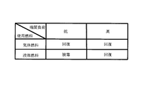
- the poisoning operation region is, for example, a region where the internal combustion engine is operated with a low load using liquid fuel.
- the recovery operation region is, for example, a region where the internal combustion engine is operated using gaseous fuel, and a region where the internal combustion engine is operated under high load using liquid fuel.
- low load operation means, for example, that the HC poisoning amount per unit time exceeds the HC poisoning recovery amount per unit time, or flows into the exhaust purification catalyst per unit time. This is an operation region in which the amount of HC to be exceeded exceeds the amount of HC oxidized by the exhaust purification catalyst per unit time.
- the “high load operation” referred to here is, for example, an operation region where the HC poisoning amount per unit time is considered to be lower than the HC poisoning recovery amount per unit time, or an exhaust purification catalyst per unit time. This is an operation region where the amount of HC flowing into the engine is considered to be less than the amount of HC oxidized by the exhaust purification catalyst per unit time.
- the determination unit determines that the internal combustion engine is operated using gaseous fuel from the integrated value of the time when the internal combustion engine has performed the low load operation using liquid fuel (hereinafter referred to as “integrated poisoning time”).
- the determination unit needs to recover the HC poisoning of the exhaust purification catalyst when the internal combustion engine is performing a low load operation using liquid fuel at the time of the previous stop of the internal combustion engine. You may judge.
- the “upper limit value” is a value that is considered that the deterioration of exhaust emission due to HC poisoning exceeds the regulation value.
- HC poisoning of the exhaust purification catalyst can be preferably eliminated in a fuel injection control system for an internal combustion engine that can use liquid fuel and gaseous fuel.
- FIG. 1 is a diagram showing a schematic configuration of an internal combustion engine to which the present invention is applied. It is a figure which shows the poisoning operation area
- FIG. 1 is a diagram showing a schematic configuration of an internal combustion engine to which the present invention is applied.
- An internal combustion engine 1 shown in FIG. 1 is a spark ignition internal combustion engine that can use liquid fuel and gaseous fuel.
- liquid fuel a non-methane hydrocarbon fuel such as a petroleum liquid fuel such as gasoline or a mixed liquid fuel obtained by mixing ethanol or methanol with a petroleum liquid fuel can be used.
- gaseous fuel compressed natural gas (CNG) can be used.
- CNG compressed natural gas
- the piston 3 is slidably loaded in the cylinder 2 of the internal combustion engine 1.
- the piston 3 is connected to an engine output shaft (crankshaft) via a connecting rod (not shown).
- the internal combustion engine 1 includes an intake port 4 for introducing fresh air (air) into the cylinder 2 and an exhaust port 5 for discharging burned gas from the cylinder 2.
- the internal combustion engine 1 includes an intake valve 6 for opening and closing the opening end of the intake port 4 and an exhaust valve 7 for opening and closing the opening end of the exhaust port 5.
- the intake valve 6 and the exhaust valve 7 are driven to open and close by an intake cam shaft and an exhaust cam shaft (not shown), respectively.
- the internal combustion engine 1 includes a spark plug 8 for generating a spark as a fire type in the cylinder 2.
- An intake passage 9 is connected to the intake port 4.
- the intake passage 9 is a passage for guiding fresh air (air) taken from the atmosphere to the intake port 4.
- an exhaust passage 10 is connected to the exhaust port 5.
- the exhaust passage 10 is a passage for discharging burned gas (exhaust gas) flowing out from the exhaust port 5 to the atmosphere after passing through exhaust purification devices 15 and 16 described later.
- the internal combustion engine 1 is provided with a supply device for selectively supplying liquid fuel and gaseous fuel to the internal combustion engine 1.
- the supply device includes a first fuel injection valve 11, a first fuel passage 110, a first fuel tank 111, a fuel pump 112, a first cutoff valve 113, a second fuel injection valve 12, and a second fuel passage. 120, a second fuel tank 121, and a regulator 122.
- the first fuel injection valve 11 and the second fuel injection valve 12 are provided for each cylinder.
- the first fuel injection valve 11 is attached to the internal combustion engine 1 near the intake port 4 and injects liquid fuel into the intake port 4.
- the first fuel injection valve 11 communicates with the first fuel tank 111 via the first fuel passage 110.
- a fuel pump 112 and a first shut-off valve 113 are disposed in the middle of the first fuel passage 110.
- the fuel pump 112 supplies the liquid fuel stored in the first fuel tank 111 to the first fuel injection valve 11.
- the first cutoff valve 113 is a device that switches between cutoff and conduction of the first fuel passage 110.
- the second fuel injection valve 12 is attached to the intake passage 9 in the vicinity of the intake port 4 and injects gaseous fuel into the intake passage 9.
- the second fuel injection valve 12 communicates with the second fuel tank (CNG cylinder) 121 via the second fuel passage 120.
- a regulator 122 and a second shut-off valve 123 are disposed in the middle of the second fuel passage 120.
- the regulator 122 is a device that depressurizes compressed natural gas (CNG) to a predetermined pressure.
- the second shutoff valve 123 is a device that switches between shutoff and conduction of the second fuel passage 120.
- the second fuel tank 121 is provided with a remaining amount sensor 124 that outputs an electrical signal correlated with the amount of gaseous fuel stored in the second fuel tank 121.
- a throttle valve 13 is disposed in the intake passage 9 upstream of the second fuel injection valve 12.
- the throttle valve 13 is a device that adjusts the amount of air introduced into the cylinder 2 by changing the passage cross-sectional area of the intake passage 9.
- An air flow meter 14 is attached to the intake passage 9 upstream of the throttle valve 13.
- the air flow meter 14 is a sensor that outputs an electrical signal correlated with the amount of air (mass) flowing through the intake passage 9.
- a first exhaust purification device 15 is disposed in the exhaust passage 10.
- the first exhaust purification device 15 contains a three-way catalyst that adsorbs nitrogen oxides (NO x ) in the exhaust when in a low temperature state.
- the first exhaust purification device 15 corresponds to an exhaust purification catalyst according to the present invention.
- a second exhaust purification device 16 is disposed in the exhaust passage 10 downstream of the first exhaust purification device 15. Similar to the first exhaust purification device 15, the second exhaust purification device 16 contains a catalyst that adsorbs nitrogen oxides (NO X ) in the exhaust.
- NO X nitrogen oxides
- An air-fuel ratio sensor 17 is disposed in the exhaust passage 10 upstream of the first exhaust purification device 15.
- the air-fuel ratio sensor 17 is a sensor that outputs an electrical signal correlated with the air-fuel ratio of the exhaust gas flowing through the exhaust passage 10.
- An O 2 sensor 18 and an exhaust temperature sensor 19 are disposed in the exhaust passage 10 downstream of the second exhaust purification device 16.
- the O 2 sensor 18 is a sensor that outputs an electrical signal that correlates with the concentration of oxygen contained in the exhaust gas.
- the exhaust temperature sensor 19 is a sensor that outputs an electrical signal correlated with the exhaust temperature.
- the internal combustion engine 1 configured as described above is provided with an electronic control unit (ECU) 20.
- the ECU 20 is electrically connected to various sensors such as the air flow meter 14, the air-fuel ratio sensor 17, the O 2 sensor 18, and the exhaust temperature sensor 19, and is configured to be able to input output signals from the various sensors.
- the ECU 20 is electrically connected to various devices such as the ignition plug 8, the first fuel injection valve 11, the second fuel injection valve 12, the throttle valve 13, the fuel pump 112, the first cutoff valve 113, and the second cutoff valve 123. It is connected and configured to be able to control various devices in accordance with the output signals of the various sensors described above.
- the ECU 20 executes a process for recovering the HC poisoning of the first exhaust purification device 15 (HC poisoning recovery process).
- HC poisoning recovery process a process for recovering the HC poisoning of the first exhaust purification device 15
- the non-methane hydrocarbons are adsorbed in the three-way catalyst in preference to NO X. Therefore, when HC poisoning occurs in which the surface of the three-way catalyst is covered with HC, the amount of NO x that can be adsorbed by the three-way catalyst decreases. For example, when the operation of the internal combustion engine 1 is stopped while the three-way catalyst is poisoned by HC, the amount of NO x that can be adsorbed by the three-way catalyst is reduced at the next start-up or warm-up operation. Further, when the internal combustion engine 1 continues the low load operation, the three-way catalyst may be deactivated even when the internal combustion engine 1 is operating.
- gaseous fuel has a lower energy storage density than the liquid fuel, there is a possibility that the amount that can be mounted on the vehicle is reduced. For this reason, if gaseous fuel is used every time HC poisoning of the three-way catalyst occurs, the consumption amount of gaseous fuel may become excessive.
- the ECU 15 uses the gaseous fuel only when the HC poisoning of the three-way catalyst cannot be recovered by using the liquid fuel. Specifically, the ECU 15 operates the internal combustion engine 1 using gaseous fuel only when the temperature of the three-way catalyst is lower than a specified value, and when the temperature of the three-way catalyst is equal to or higher than the specified temperature, the ECU 15 supplies liquid fuel. The internal combustion engine 1 was operated by using it.
- the specified value is equal to the HC poisoning amount per unit time with respect to the HC poisoning amount per unit time (for example, the HC amount adhering to the exhaust purification catalyst) when the internal combustion engine is operated with liquid fuel.
- This is the temperature of the exhaust purification catalyst when the recovery amount (for example, the amount of HC oxidized by the exhaust purification catalyst) increases, and is a value obtained in advance by an adaptation process using experiments or the like.
- the specified value may be changed according to the measurement value of the remaining amount sensor 124.
- the specified value may be set higher when the measured value of the remaining amount sensor 124 is larger than when the measured value is small.
- the HC poisoning recovery process can be performed while suppressing the consumption of gaseous fuel, and the remaining amount of gaseous fuel can be reduced.
- the amount is large, HC poisoning can be quickly eliminated.
- the specified value is set to an excessively high value, the consumption amount of gaseous fuel is increased. Therefore, it is desirable to set an upper limit guard for the specified value.
- the amount of HC adhering to the three-way catalyst (HC poisoning amount) is obtained from the operation history of the internal combustion engine 1, A method of determining that HC poisoning has occurred on the condition that the amount of HC poisoning exceeds the upper limit value can be used.
- a specific method for obtaining the amount of HC poisoning is a first integrated value of time during which the internal combustion engine 1 is operated in an operation region in which HC poisoning is promoted (hereinafter referred to as “poisoning operation region”).
- the integrated value and the second integrated value that is the integrated value of the time during which the internal combustion engine 1 is operated in the operating region where the HC poisoning is recovered (hereinafter referred to as “recovery operating region”) are calculated.
- a method in which a value obtained by subtracting the second integrated value is used as a correlation value of the HC poisoning amount can be used.
- the poisoning operation region and the recovery operation region for each fuel used are shown in FIG.
- the internal combustion engine 1 is operated using gaseous fuel
- HC poisoning is recovered from the low load operation region to the high load operation region.
- the internal combustion engine 1 is operated using liquid fuel
- HC poisoning is promoted in the low load operation region
- HC poisoning is recovered in the high load operation region.
- the low load operation region shown in FIG. 2 is an operation that is lower than the engine load (hereinafter referred to as “reference load”) when the HC poisoning amount per unit time and the HC poisoning recovery amount per unit time are equal. It is an area.
- the reference load is obtained in advance by an adaptation operation using an experiment or the like, and is stored in the ROM of the ECU 15 or the like.
- the reference load may be an engine load when the amount of HC flowing into the three-way catalyst per unit time is equal to the amount of HC oxidized by the three-way catalyst per unit time.
- the ECU 15 calculates the first integrated value by integrating the time during which the liquid fuel is used as the fuel of the internal combustion engine 1 and the engine load is lower than the reference load. Further, the ECU 15 accumulates the time that the internal combustion engine 1 has been operated with gaseous fuel, and also accumulates the time that the liquid fuel is used as the fuel of the internal combustion engine 1 and the engine load is equal to or higher than the reference load. Then, the second integrated value is calculated by adding the integrated values.
- the ECU 15 calculates the correlation value of the HC poisoning amount by subtracting the second integrated value from the first integrated value. Next, the ECU 15 determines that the three-way catalyst needs to be recovered from the HC poisoning if the correlation value of the HC poisoning amount exceeds the upper limit value.
- the upper limit value is a value at which the exhaust emission (NO X amount exhausted into the atmosphere) due to HC poisoning exceeds the regulation value.
- the first integrated value may be corrected according to the alcohol concentration in the liquid fuel.
- the alcohol concentration of the liquid fuel is high, more non-methane hydrocarbons are contained in the exhaust than when the alcohol concentration is low. Therefore, when the alcohol concentration in the liquid fuel is high, correction may be performed so that the first integrated value becomes larger than when the alcohol concentration is low.
- the alcohol concentration contained in the liquid fuel may be detected by attaching an alcohol concentration sensor to the liquid fuel passage from the first fuel tank 111 to the first fuel injection valve 11, or a correction used for air-fuel ratio feedback control. You may estimate from a coefficient.
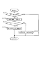
- FIG. 3 is a flowchart showing an HC poisoning recovery processing routine.
- the HC poisoning recovery process routine is a routine stored in advance in the ROM of the ECU 15 and is periodically executed by the ECU 15.
- the ECU 15 first determines whether or not HC poisoning of the three-way catalyst has occurred in S101. Specifically, the ECU 15 determines whether or not HC poisoning of the three-way catalyst has occurred by executing the HC poisoning determination processing routine shown in FIG.
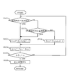
- the HC poisoning determination processing routine shown in FIG. 4 is a routine that is stored in advance in the ROM of the ECU 15, and is a routine that is periodically executed by the ECU 15.
- the ECU 15 determines in S201 whether or not the fuel used in the internal combustion engine 1 is gaseous fuel, that is, whether or not the internal combustion engine 1 is operated by gaseous fuel. To do.
- the ECU 15 proceeds to S202.
- the ECU 15 determines whether or not the engine load is greater than or equal to the reference load described above.
- the ECU 15 proceeds to S204.
- the arithmetic unit according to the present invention is realized by the ECU 15 executing the processing of S203 or S204.
- the ECU 15 proceeds to S205 after executing the process of S203 or S204.
- the ECU 15 determines whether or not the difference ⁇ t calculated in S205 is larger than the upper limit value ⁇ . If a negative determination is made in S205 ( ⁇ t ⁇ ⁇ ), the ECU 15 returns to S201. On the other hand, if an affirmative determination is made in S205 ( ⁇ t> ⁇ ), the ECU 15 proceeds to S206 and determines that HC poisoning of the three-way catalyst has occurred.
- the determination unit according to the present invention is realized by the ECU 15 executing the processes of S205 and S206.
- the ECU 15 acquires the temperature (catalyst temperature) T of the three-way catalyst.
- the catalyst temperature T a measured value of a temperature sensor that directly detects the bed temperature of the three-way catalyst may be used, or a measured value of the exhaust temperature sensor 19 may be used.
- the acquisition unit according to the present invention is realized.
- the ECU 15 determines whether or not the catalyst temperature T acquired in S102 is less than a specified value Tbase. When an affirmative determination is made in S103 (T ⁇ Tbase), the ECU 15 proceeds to S104 and operates the internal combustion engine 1 with gaseous fuel. On the other hand, if a negative determination is made in S103 (T ⁇ Tbase), the ECU 15 proceeds to S105 and operates the internal combustion engine 1 with liquid fuel.
- the control part concerning this invention is implement
- HC poisoning of the first exhaust purification device 15 is eliminated while suppressing the consumption amount of gaseous fuel. It becomes possible to do.
- determining may determine whether the HC poisoning of the three-way catalyst has occurred based on the amount of the NO X discharged from the first exhaust gas purification device 15. For example, downstream of the first exhaust gas purification device 15, and the NO X sensor arranged from the second exhaust gas purification device 16 in the exhaust passage upstream of the three-way catalyst when the measured value of the NO X sensor exceeds a predetermined value It may be determined that HC poisoning has occurred.
Landscapes
- Engineering & Computer Science (AREA)
- Chemical & Material Sciences (AREA)
- Combustion & Propulsion (AREA)
- Mechanical Engineering (AREA)
- General Engineering & Computer Science (AREA)
- Oil, Petroleum & Natural Gas (AREA)
- Health & Medical Sciences (AREA)
- Chemical Kinetics & Catalysis (AREA)
- Toxicology (AREA)
- Exhaust Gas After Treatment (AREA)
- Output Control And Ontrol Of Special Type Engine (AREA)
Abstract
Description
内燃機関の排気通路に配置された排気浄化用触媒の温度を取得する取得部と、
前記排気浄化用触媒のHC被毒が発生したときに、前記取得部により取得された温度が規定値未満であれば気体燃料により内燃機関を運転させ、前記取得部により取得された温度が規定値以上であれば高ければ液体燃料により内燃機関を運転させる制御部と、
を備えるようにした。
内燃機関がHC被毒を促進させる運転領域(以下、「被毒運転領域」と称する)において運転された時間の積算値である第1積算値と、内燃機関がHC被毒を回復させる運転領域(以下、「回復運転領域」と称する)において運転された時間の積算値である第2積算値と、を演算する演算部と、
第1積算値から第2積算値を減算した値が上限値を超えたときに排気浄化用触媒のHC被毒が発生していると判定する判定部と、
を更に備えるようにしてもよい。
2 気筒
3 ピストン
9 吸気通路
10 排気通路
11 第1燃料噴射弁
12 第2燃料噴射弁
15 第1排気浄化装置
16 第2排気浄化装置
17 空燃比センサ
18 O2センサ
19 排気温度センサ
110 第1燃料通路
111 第1燃料タンク
112 第1燃料ポンプ
113 第1遮断弁
120 第2燃料通路
121 第2燃料タンク
122 レギュレータ
123 第2遮断弁
124 残量センサ
Claims (4)
- 液体燃料と気体燃料を使用可能な内燃機関の燃料噴射制御システムにおいて、
内燃機関の排気通路に配置された排気浄化用触媒の温度を取得する取得部と、
前記排気浄化用触媒のHC被毒が発生したときに、前記取得部により取得された温度が規定値未満であれば気体燃料により内燃機関を運転させ、前記取得部により取得された温度が規定値以上であれば液体燃料により内燃機関を運転させる制御部と、
を備える内燃機関の燃料噴射制御システム。 - 請求項1において、気体燃料の残量が多いときは少ないときに比べ、規定値が高くされる内燃機関の燃料噴射制御システム。
- 請求項1または2において、前記内燃機関が前記HC被毒を促進させる運転条件により運転された時間の積算値である第1積算値と、前記内燃機関が前記HC被毒を回復させる運転条件により運転された時間の積算値である第2積算値と、を演算する演算部と、
前記第1積算値から前記第2積算値を減算した値が上限値を超えたときに、前記排気浄化用触媒のHC被毒が発生していると判定する判定部と、
を更に備える内燃機関の燃料噴射制御システム。 - 請求項1乃至3の何れか1項において、前記液体燃料は非メタン系の炭化水素燃料であり、前記気体燃料は天然ガス燃料である内燃機関の燃料噴射制御システム。
Priority Applications (5)
| Application Number | Priority Date | Filing Date | Title |
|---|---|---|---|
| PCT/JP2011/059196 WO2012140753A1 (ja) | 2011-04-13 | 2011-04-13 | 内燃機関の燃料噴射制御システム |
| CN201180070079.XA CN103477056B (zh) | 2011-04-13 | 2011-04-13 | 内燃机的燃料喷射控制系统 |
| DE112011105149.2T DE112011105149T5 (de) | 2011-04-13 | 2011-04-13 | Kraftstoffeinspritzsteuersystem einer Maschine mit interner Verbrennung |
| US14/111,428 US9169758B2 (en) | 2011-04-13 | 2011-04-13 | Fuel injection control system of an internal combustion engine |
| JP2013509704A JP5582249B2 (ja) | 2011-04-13 | 2011-04-13 | 内燃機関の燃料噴射制御システム |
Applications Claiming Priority (1)
| Application Number | Priority Date | Filing Date | Title |
|---|---|---|---|
| PCT/JP2011/059196 WO2012140753A1 (ja) | 2011-04-13 | 2011-04-13 | 内燃機関の燃料噴射制御システム |
Publications (1)
| Publication Number | Publication Date |
|---|---|
| WO2012140753A1 true WO2012140753A1 (ja) | 2012-10-18 |
Family
ID=47008959
Family Applications (1)
| Application Number | Title | Priority Date | Filing Date |
|---|---|---|---|
| PCT/JP2011/059196 Ceased WO2012140753A1 (ja) | 2011-04-13 | 2011-04-13 | 内燃機関の燃料噴射制御システム |
Country Status (5)
| Country | Link |
|---|---|
| US (1) | US9169758B2 (ja) |
| JP (1) | JP5582249B2 (ja) |
| CN (1) | CN103477056B (ja) |
| DE (1) | DE112011105149T5 (ja) |
| WO (1) | WO2012140753A1 (ja) |
Families Citing this family (2)
| Publication number | Priority date | Publication date | Assignee | Title |
|---|---|---|---|---|
| JP6551385B2 (ja) * | 2016-12-26 | 2019-07-31 | トヨタ自動車株式会社 | 内燃機関の排気浄化装置 |
| JP6604323B2 (ja) * | 2016-12-28 | 2019-11-13 | トヨタ自動車株式会社 | 内燃機関の排ガス浄化システム及び排ガス浄化用触媒の使用方法 |
Citations (3)
| Publication number | Priority date | Publication date | Assignee | Title |
|---|---|---|---|---|
| JP2009264282A (ja) * | 2008-04-25 | 2009-11-12 | Toyota Motor Corp | 内燃機関の排気ガス浄化装置 |
| JP2010025015A (ja) * | 2008-07-22 | 2010-02-04 | Toyota Motor Corp | 内燃機関の排気ガス浄化装置 |
| JP2011069323A (ja) * | 2009-09-28 | 2011-04-07 | Ud Trucks Corp | ディーゼルエンジンの排気浄化装置 |
Family Cites Families (6)
| Publication number | Priority date | Publication date | Assignee | Title |
|---|---|---|---|---|
| JPS58200049A (ja) * | 1982-05-17 | 1983-11-21 | Nippon Jidosha Kenkyusho | アルコ−ル燃料エンジンの始動装置 |
| JP3712314B2 (ja) * | 1997-08-08 | 2005-11-02 | 株式会社日本自動車部品総合研究所 | 排気浄化用触媒の炭化水素吸着量検出装置 |
| JP2002038980A (ja) | 2000-07-27 | 2002-02-06 | Fuji Heavy Ind Ltd | エンジンの燃料切換制御装置 |
| JP4310729B2 (ja) | 2003-02-05 | 2009-08-12 | トヨタ自動車株式会社 | 多種燃料エンジン |
| JP4449956B2 (ja) * | 2006-08-04 | 2010-04-14 | トヨタ自動車株式会社 | 内燃機関 |
| US20090071452A1 (en) * | 2007-09-14 | 2009-03-19 | Patrick Joseph Phlips | Bi-fuel Engine Using Hydrogen |
-
2011
- 2011-04-13 CN CN201180070079.XA patent/CN103477056B/zh not_active Expired - Fee Related
- 2011-04-13 JP JP2013509704A patent/JP5582249B2/ja not_active Expired - Fee Related
- 2011-04-13 WO PCT/JP2011/059196 patent/WO2012140753A1/ja not_active Ceased
- 2011-04-13 DE DE112011105149.2T patent/DE112011105149T5/de not_active Ceased
- 2011-04-13 US US14/111,428 patent/US9169758B2/en not_active Expired - Fee Related
Patent Citations (3)
| Publication number | Priority date | Publication date | Assignee | Title |
|---|---|---|---|---|
| JP2009264282A (ja) * | 2008-04-25 | 2009-11-12 | Toyota Motor Corp | 内燃機関の排気ガス浄化装置 |
| JP2010025015A (ja) * | 2008-07-22 | 2010-02-04 | Toyota Motor Corp | 内燃機関の排気ガス浄化装置 |
| JP2011069323A (ja) * | 2009-09-28 | 2011-04-07 | Ud Trucks Corp | ディーゼルエンジンの排気浄化装置 |
Also Published As
| Publication number | Publication date |
|---|---|
| CN103477056A (zh) | 2013-12-25 |
| US9169758B2 (en) | 2015-10-27 |
| DE112011105149T5 (de) | 2014-01-23 |
| US20140033687A1 (en) | 2014-02-06 |
| CN103477056B (zh) | 2016-08-17 |
| JP5582249B2 (ja) | 2014-09-03 |
| JPWO2012140753A1 (ja) | 2014-07-28 |
Similar Documents
| Publication | Publication Date | Title |
|---|---|---|
| US8904756B2 (en) | Exhaust emission control system of internal combustion engine | |
| JP5861720B2 (ja) | 内燃機関の制御装置 | |
| US9617900B2 (en) | Deterioration diagnosis device for an exhaust gas purification apparatus | |
| US20170167352A1 (en) | Deterioration diagnosis apparatus for selective catalytic reduction catalyst | |
| US6546719B2 (en) | Air-fuel ratio control apparatus of internal combustion engine | |
| JP5352917B2 (ja) | 燃料蒸気制御システム及び制御方法 | |
| JP5105001B2 (ja) | 車両制御装置 | |
| JP5582249B2 (ja) | 内燃機関の燃料噴射制御システム | |
| EP2682589B1 (en) | Control device for internal combustion engine | |
| JP5067510B2 (ja) | 内燃機関の燃料噴射システム | |
| US8789357B2 (en) | Catalyst deterioration detection apparatus and method | |
| JP2003106197A (ja) | 内燃機関の空燃比制御装置 | |
| JP2009133279A (ja) | 燃料供給制御装置および燃料供給制御方法 | |
| JP4224826B2 (ja) | ガス燃料エンジンシステム | |
| JP2005273585A (ja) | ガス燃料エンジンの付臭剤処理装置 | |
| JP4657111B2 (ja) | 内燃機関の炭化水素吸着材パージ制御装置 | |
| JP3627568B2 (ja) | 燃料遮断弁制御装置 | |
| WO2012147183A1 (ja) | 内燃機関の制御システム | |
| WO2012153424A1 (ja) | 多種燃料内燃機関の制御システム | |
| JP4455931B2 (ja) | 吸着材劣化判断装置および吸着材劣化判断方法 | |
| JP2009287533A (ja) | 内燃機関の蒸発燃料処理装置 | |
| JP2001050114A (ja) | 気体燃料車の内燃機関制御装置 | |
| WO2012147184A1 (ja) | 内燃機関の制御システム | |
| JP2008128005A (ja) | 内燃機関の触媒異常診断装置 | |
| WO2012153423A1 (ja) | 多種燃料内燃機関の制御システム |
Legal Events
| Date | Code | Title | Description |
|---|---|---|---|
| 121 | Ep: the epo has been informed by wipo that ep was designated in this application |
Ref document number: 11863590 Country of ref document: EP Kind code of ref document: A1 |
|
| ENP | Entry into the national phase |
Ref document number: 2013509704 Country of ref document: JP Kind code of ref document: A |
|
| WWE | Wipo information: entry into national phase |
Ref document number: 14111428 Country of ref document: US |
|
| WWE | Wipo information: entry into national phase |
Ref document number: 112011105149 Country of ref document: DE Ref document number: 1120111051492 Country of ref document: DE |
|
| 122 | Ep: pct application non-entry in european phase |
Ref document number: 11863590 Country of ref document: EP Kind code of ref document: A1 |