WO2012133843A1 - ガラス板の製造方法 - Google Patents
ガラス板の製造方法 Download PDFInfo
- Publication number
- WO2012133843A1 WO2012133843A1 PCT/JP2012/058716 JP2012058716W WO2012133843A1 WO 2012133843 A1 WO2012133843 A1 WO 2012133843A1 JP 2012058716 W JP2012058716 W JP 2012058716W WO 2012133843 A1 WO2012133843 A1 WO 2012133843A1
- Authority
- WO
- WIPO (PCT)
- Prior art keywords
- temperature
- glass
- sheet glass
- control step
- width direction
- Prior art date
- Legal status (The legal status is an assumption and is not a legal conclusion. Google has not performed a legal analysis and makes no representation as to the accuracy of the status listed.)
- Ceased
Links
Images


Classifications
-
- C—CHEMISTRY; METALLURGY
- C03—GLASS; MINERAL OR SLAG WOOL
- C03B—MANUFACTURE, SHAPING, OR SUPPLEMENTARY PROCESSES
- C03B18/00—Shaping glass in contact with the surface of a liquid
- C03B18/02—Forming sheets
- C03B18/04—Changing or regulating the dimensions of the molten glass ribbon
- C03B18/06—Changing or regulating the dimensions of the molten glass ribbon using mechanical means, e.g. restrictor bars, edge rollers
-
- C—CHEMISTRY; METALLURGY
- C03—GLASS; MINERAL OR SLAG WOOL
- C03B—MANUFACTURE, SHAPING, OR SUPPLEMENTARY PROCESSES
- C03B17/00—Forming molten glass by flowing-out, pushing-out, extruding or drawing downwardly or laterally from forming slits or by overflowing over lips
- C03B17/06—Forming glass sheets
- C03B17/067—Forming glass sheets combined with thermal conditioning of the sheets
-
- C—CHEMISTRY; METALLURGY
- C03—GLASS; MINERAL OR SLAG WOOL
- C03B—MANUFACTURE, SHAPING, OR SUPPLEMENTARY PROCESSES
- C03B17/00—Forming molten glass by flowing-out, pushing-out, extruding or drawing downwardly or laterally from forming slits or by overflowing over lips
- C03B17/06—Forming glass sheets
- C03B17/064—Forming glass sheets by the overflow downdraw fusion process; Isopipes therefor
-
- C—CHEMISTRY; METALLURGY
- C03—GLASS; MINERAL OR SLAG WOOL
- C03B—MANUFACTURE, SHAPING, OR SUPPLEMENTARY PROCESSES
- C03B18/00—Shaping glass in contact with the surface of a liquid
- C03B18/02—Forming sheets
- C03B18/18—Controlling or regulating the temperature of the float bath; Composition or purification of the float bath
Definitions
- the present invention relates to a method for producing a glass plate.
- Patent Document 1 Japanese Patent Application Laid-Open No. 2004-115357
- molten glass is poured into a molded body, and then the molten glass is allowed to overflow from the top of the molded body.
- the overflowed molten glass flows down along both side surfaces of the molded body, and becomes a sheet-like glass (sheet glass) by joining at the lower end of the molded body. Thereafter, the sheet glass is pulled downward by a roller and cut into a predetermined length.
- the residual stress of the sheet glass is reduced by setting the temperature gradient between the central portion in the width direction of the sheet glass and the vicinity of the end portion in a predetermined temperature region to a predetermined value. Further, in the invention disclosed in Patent Document 1, a temperature gradient between the central portion of the sheet glass and the vicinity of the end portion is defined in consideration of the residual stress and distortion of the sheet glass.
- an object of the present invention is to provide a method for producing a glass plate, which can make the plate thickness of the sheet glass as uniform as possible and reduce warpage and distortion (residual stress).
- the method for producing a glass plate of the present invention is a method for producing a glass plate by a downdraw method, and includes a forming step and a cooling step.
- the forming step the molten glass is allowed to flow along both side surfaces of the formed body and is joined at the lower portion of the formed body to form the sheet glass.
- the cooling step the sheet glass is cooled while being pulled downward by a roller.
- a glass strain point upper temperature control process is performed.
- the glass strain point upper temperature control step is a step of performing temperature control in the width direction of the sheet glass in a temperature region from the lower part of the molded body to a temperature region near the glass strain point, the first temperature control step And a second temperature control step and a third temperature control step.
- the end portion in the width direction of the sheet glass is lower than the temperature of the central region sandwiched between the end portions, and the temperature of the central region is made uniform.
- the temperature in the width direction of the sheet glass is lowered from the center toward the end.
- the temperature gradient between the end portion and the center portion of the sheet glass in the width direction is eliminated in the temperature region near the glass strain point.
- board thickness of sheet glass can be made uniform as much as possible, and a curvature and distortion (residual stress) can be reduced.
- region of sheet glass is an area
- the edge part of sheet glass is an area
- the viscosity of the end portion of the sheet glass is increased. Thereby, the shrinkage
- the plate thickness can be made uniform by making the temperature of the end portion in the width direction of the sheet glass lower than the temperature of the central region.
- the viscosity of the central region becomes uniform by making the temperature of the central region of the sheet glass uniform. Thereby, the plate
- the sheet glass is cooled so as to reduce the temperature gradient formed in the second temperature control step toward the temperature region near the glass strain point.
- tensile stress acts at the central portion of the sheet glass.
- a tensile stress acts in the flow direction and the width direction of the sheet glass at the center of the sheet glass.
- the tensile stress acting in the flow direction of the sheet glass is larger than the tensile stress acting in the width direction of the sheet glass. Since the sheet can be cooled while maintaining the flatness of the sheet glass by the tensile stress, the warp of the sheet glass can be reduced.
- the sheet glass has a temperature gradient at the glass strain point, the sheet glass is distorted when cooled to room temperature. Accordingly, in the third temperature control step, the strain after cooling can be reduced by cooling so as to reduce the temperature gradient toward the temperature region near the glass strain point. In the sheet glass cooled in the third temperature control step, it is preferable that the value obtained by subtracting the temperature at the end from the temperature at the center in the width direction falls within a range from ⁇ 20 ° C. to 20 ° C.
- the temperature gradient in the width direction of the sheet glass gradually decreases as it goes in the flow direction of the sheet glass.
- the temperature gradient is formed so that the temperature in the width direction of the sheet glass gradually decreases from the central portion toward the end portion.
- a temperature gradient is formed so that the temperature in the width direction of the sheet glass gradually decreases from the central portion toward the end portion, and as the temperature gradient goes in the flow direction of the sheet glass. It is more preferable to decrease gradually.
- the temperature gradient is formed so that the temperature in the width direction of the sheet glass gradually decreases in a convex shape from the central portion toward the end portion.
- a temperature gradient is formed so that the temperature in the width direction of the sheet glass gradually decreases in a convex shape from the center portion toward the end portion, and this temperature gradient is the flow direction of the sheet glass. It is more preferable to decrease gradually as it goes to.
- the first temperature control step is performed when the temperature of the central portion of the sheet glass is equal to or higher than the glass softening point.
- the temperature of the central portion of the sheet glass is glass. It is preferably performed when it is lower than the softening point.
- the first temperature control step the temperature of the central region of the sheet glass is controlled to be uniform, and after the plate thickness of the sheet glass is uniform, the second temperature control step and the third temperature control step are performed. Done. Accordingly, a tensile stress can be applied to the central portion of the sheet glass having a uniform thickness in the flow direction and the width direction of the sheet glass. Thereby, sheet glass can be cooled, maintaining the flatness of sheet glass. Accordingly, warpage of the sheet glass can be reduced.
- the temperature difference between the end portion in the width direction and the center portion of the sheet glass in the cooling step is minimized. If the sheet glass has a temperature difference at the glass strain point, the sheet glass is distorted after being cooled to room temperature. That is, in the temperature region near the glass strain point, the strain of the sheet glass can be reduced by reducing the temperature difference between the end portion and the center portion in the width direction of the sheet glass.
- the value obtained by subtracting the temperature at the end from the temperature at the center in the width direction of the sheet glass falls within a range from -20 ° C to 20 ° C.
- the glass strain point upper temperature control step is a fourth temperature control in which the temperature in the width direction of the sheet glass is lowered from the end toward the center in a temperature range lower than the temperature range near the glass strain point. It is preferable to further include a step. Thereby, the cooling amount of sheet glass becomes large as it goes to the center part from the edge part of sheet glass. Therefore, as described above, tensile stress acts on the central portion of the sheet glass in the flow direction and the width direction of the sheet glass. Therefore, since it can cool, maintaining the flatness of sheet glass, the curvature of sheet glass can be reduced.
- a temperature gradient is formed so that the temperature of the sheet glass gradually decreases from the end in the width direction toward the center in a temperature range lower than the temperature range near the glass strain point. Is preferred.
- a temperature gradient is formed so that the temperature of the sheet glass gradually decreases in a convex shape from the end in the width direction toward the center in a temperature range lower than the temperature range near the glass strain point. It is preferred that
- the fourth temperature control step it is preferable to increase the temperature gradient between the end portion and the center portion in the width direction of the sheet glass in the flow direction of the sheet glass.
- the fourth temperature control step it is preferable to gradually increase the temperature gradient between the width direction end portion and the center portion of the sheet glass in the flow direction of the sheet glass.
- the sheet glass preferably has a strain value of 1.0 nm or less, more preferably has a strain value in the range of 0 nm to 0.95 nm, and has a strain value in the range of 0 nm to 0.90 nm. More preferably.
- the sheet glass preferably has a warp value of 0.15 mm or less, more preferably has a warp value in the range of 0 mm to 0.10 mm, and has a warp value in the range of 0 mm to 0.05 mm. More preferably.
- the sheet glass preferably has a thickness deviation of 15 ⁇ m or less, more preferably has a thickness deviation in the range of 0 ⁇ m to 14 ⁇ m, and further has a thickness deviation in the range of 0 ⁇ m to 13 ⁇ m. preferable.
- the thickness of the sheet glass can be made as uniform as possible, and warpage and distortion (residual stress) can be reduced.
- the flowchart of a part of manufacturing method of the glass plate which concerns on this embodiment.
- the schematic diagram which mainly shows the melting
- FIG. 1 is a partial flowchart of the glass plate manufacturing method according to the present embodiment. Hereinafter, the manufacturing method of a glass plate is demonstrated using FIG.
- the glass plate is manufactured through various processes including a melting process ST1, a clarification process ST2, a homogenization process ST3, a molding process ST4, a cooling process ST5, and a cutting process ST6.
- a melting process ST1 a clarification process ST2, a homogenization process ST3, a molding process ST4, a cooling process ST5, and a cutting process ST6.
- the glass raw material is heated and melted.
- the glass raw material has a composition such as SiO 2 or Al 2 O 3 .
- the completely melted glass raw material becomes molten glass.
- the molten glass is clarified. Specifically, the gas component contained in the molten glass is released from the molten glass, or the gas component contained in the molten glass is absorbed into the molten glass.
- the molten glass is homogenized.
- the temperature of the molten glass that has been clarified is adjusted.
- the molten glass is formed into a sheet-like sheet glass SG (see FIGS. 3 and 4) by a down draw method (specifically, an overflow down draw method).
- the sheet glass SG formed in the forming step ST4 is cooled.
- the sheet glass SG is cooled to near room temperature.
- the sheet glass SG cooled to near room temperature is cut every predetermined length to obtain a cut sheet glass SG1 (see FIG. 3).
- the cut sheet glass SG1 cut at every predetermined length is then further cut and ground, polished, washed and inspected to form a glass plate, which is used for a flat panel display such as a liquid crystal display. .
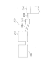
- FIG. 2 is a schematic diagram mainly showing a melting apparatus 200 included in the glass plate manufacturing apparatus 100.
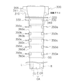
- FIG. 3 is a schematic front view of a forming apparatus 300 included in the glass plate manufacturing apparatus 100.
- FIG. 4 is a schematic side view of the molding apparatus 300.
- the glass plate manufacturing apparatus 100 will be described.
- the glass plate manufacturing apparatus 100 mainly includes a melting apparatus 200 (see FIG. 2), a forming apparatus 300 (see FIGS. 2 to 4), and a cutting apparatus 400 (see FIG. 3).
- the dissolution device 200 is a device for performing the dissolution step ST1, the clarification step ST2, and the homogenization step ST3.
- the dissolution apparatus 200 includes a dissolution tank 201, a clarification tank 202, a stirring tank 203, a first pipe 204, and a second pipe 205.
- the melting tank 201 is a tank for melting the glass raw material. In the dissolution tank 201, the dissolution step ST1 is performed.
- the clarification tank 202 is a tank for removing bubbles from the molten glass melted in the melting tank 201. By further heating the molten glass fed from the melting tank 201 in the clarification tank 202, defoaming of bubbles in the molten glass is promoted. In the clarification tank 202, a clarification step ST2 is performed.
- the stirring tank 203 has a stirring device including a container for containing molten glass, a rotating shaft, and a stirring blade attached to the rotating shaft.
- a container a rotating shaft, and a stirring blade, although the thing made from platinum group elements, such as platinum, or the alloy of a platinum group element, for example can be used, it is not restricted to this.
- a driving unit such as a motor
- the stirring blade attached to the rotating shaft stirs the molten glass.
- the homogenization step ST3 is performed.
- the first piping 204 and the second piping 205 are piping made of a platinum group element or a platinum group element alloy.
- the first pipe 204 is a pipe that connects the clarification tank 202 and the stirring tank 203.
- the second pipe 205 is a pipe that connects the stirring tank 203 and the molding apparatus 300.
- the molding device 300 is a device for performing the molding step ST4 and the cooling step ST5.
- the molding apparatus 300 includes a molded body 310, an atmosphere partition member 320, a cooling roller 330, a cooling unit 340, pulling rollers 350a to 350e, and heaters 360a to 360e. .
- these configurations will be described.
- the molded body 310 is an apparatus for performing the molding process ST4.
- the molded body 310 is located in the upper part of the molding apparatus 300, and the molten glass flowing from the melting apparatus 200 is molded into a sheet-like glass plate (sheet glass SG) by the overflow down draw method. It has the function to do.
- the molded body 310 has a wedge-shaped cross section cut in the vertical direction, and is formed of bricks.
- a supply port 311 is formed in the molded body 310 on the upstream side in the flow direction of the molten glass flowing from the melting device 200. Further, as shown in FIG. 3, the molded body 310 is formed with a groove portion 312 opened upward along the longitudinal direction thereof. The groove 312 is formed so as to gradually become shallower from the upstream side in the flow direction of the molten glass toward the downstream side.
- the molten glass flowing from the melting device 200 toward the molding device 300 flows into the groove 312 of the molded body 310 through the supply port 311.
- the molten glass that has flowed into the groove 312 of the molded body 310 overflows at the top of the groove 312 and flows down along both side surfaces 313 of the molded body 310. And the molten glass which flows down along the both side surfaces 313 of the molded object 310 merges in the lower part 314 of the molded object 310, and turns into the sheet glass SG.
- Atmosphere partition member 320 As shown in FIGS. 3 and 4, the atmosphere partition member 320 is a plate-like member disposed in the vicinity of the lower portion 314 of the molded body 310.
- the atmosphere partition member 320 is disposed so as to be substantially horizontal on both sides in the thickness direction of the sheet glass SG flowing down from the lower portion 314 of the molded body 310.
- the atmosphere partition member 320 functions as a heat insulating material. In other words, the atmosphere partition member 320 suppresses the movement of heat from the upper side to the lower side of the atmosphere partition member 320 by partitioning the upper and lower air.
- Cooling roller 330 The cooling roller 330 is disposed below the atmosphere partition member 320. Moreover, the cooling roller 330 is arrange
- the cooling roller 330 also has a role of pulling the sheet glass SG downward by transmitting a driving force by the cooling roller driving motor 390 (see FIG. 5).
- the sheet glass SG is stretched to a predetermined thickness by the cooling roller 330.
- Cooling unit 340 is an air-cooling type cooling device, and cools the ambient temperature of the sheet glass SG passing through the cooling roller 330 and the lower side thereof.
- a plurality of cooling units 340 are arranged in the width direction of the sheet glass SG (here, three) and a plurality of cooling units 340 are arranged in the flow direction thereof. Specifically, the cooling units 340 are arranged one by one so as to face the surfaces of the ears R and L of the sheet glass SG, and in a central area CA (see FIG. 4 and FIG. 7) described later. One is arranged so as to face the surface.
- the pulling rollers 350a to 350e are arranged below the cooling roller 330 with a predetermined interval in the flow direction of the sheet glass SG. Further, the pulling rollers 350a to 350e are respectively arranged on both sides in the thickness direction of the sheet glass SG and so as to face both end portions in the width direction of the sheet glass SG. The pulling rollers 350a to 350e are both in the thickness direction of the sheet glass SG where the viscosities of the ears R and L are equal to or higher than a predetermined value in the cooling roller 330, while being in contact with both end portions in the width direction. The sheet glass SG is pulled downward.
- the pulling rollers 350a to 350e are driven by the driving force transmitted by the pulling roller driving motor 391 (see FIG. 5).
- the peripheral speed of the pulling rollers 350 a to 350 e is larger than the peripheral speed of the cooling roller 330.
- the circumferential speed of the pulling roller increases as it is arranged on the downstream side in the flow direction of the sheet glass SG. That is, among the plurality of pulling rollers 350a to 350e, the peripheral speed of the pulling roller 350a is the lowest, and the peripheral speed of the pulling roller 350e is the highest.
- (2-2-6) Heater A plurality of (here, five) heaters are arranged in the flow direction of the sheet glass SG and a plurality (here, five) in the width direction of the sheet glass SG.
- the heaters 360a to 360e control the ambient temperature in the vicinity of the sheet glass SG pulled downward by the pulling rollers 350a to 350e by controlling the output by the control device 500 described later (specifically, the temperature rises). It functions as a temperature control device.
- a plurality of heaters arranged in the width direction of the sheet glass SG are respectively an ear portion L, a left portion CL (see FIG. 4 and FIG. 7), and a central portion C (see FIG. 4 and FIG. 7), the ambient temperature of the right part CR (see FIG. 4 and FIG. 7) and the ear part R is controlled.
- the atmospheric temperature of the sheet glass SG pulled downward by the pulling rollers 350a to 350e is controlled by the heaters 360a to 360e (specifically, the atmospheric temperature of the sheet glass SG is controlled).
- the sheet glass SG is cooled so that the sheet glass SG transitions from the viscous region to the elastic region through the viscoelastic region.
- thermocouples (here, thermocouple units 380 (see FIG. 5)) serving as ambient temperature detecting means for detecting the ambient temperature of each region of the sheet glass SG. ) are arranged so as to correspond to the heaters 360a to 360e, respectively. That is, a plurality of thermocouples are arranged in the flow direction of the sheet glass SG and a plurality in the width direction.
- the process in which the sheet glass SG is cooled by the cooling roller 330, the cooling unit 340, and the heaters 360a to 360e in the region below the lower part 314 of the molded body 310 is the cooling process ST5.
- the cutting device 400 is a device that cuts the sheet glass SG flowing down in the forming device 300 from a direction perpendicular to the longitudinal surface thereof. Thereby, the sheet-like sheet glass SG becomes a plurality of cut sheet glasses SG1 having a predetermined length.
- the cutting device 400 is driven by a cutting device drive motor 392 (see FIG. 5).
- Control device 500 FIG. 5 is a control block diagram of the control device 500.
- the control device 500 includes a CPU, a ROM, a RAM, a hard disk, and the like, and functions as a control unit that controls various devices included in the glass plate manufacturing apparatus 100.
- the control device 500 includes various sensors (for example, a thermocouple unit 380) and switches (for example, a main power switch 381) included in the glass plate manufacturing apparatus 100. , A cooling unit 340, heaters 360a to 360e, a cooling roller driving motor 390, a pulling roller driving motor 391, and a cutting device driving motor 392 in response to an input signal from an operator via an input device (not shown) or the like. Etc. are controlled.
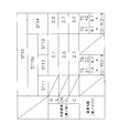
- FIG. 6 is a table showing the temperature of the sheet glass SG in each temperature profile (described later).
- FIG. 7 is a graph of the temperature profile in the table of FIG.
- FIG. 8 is a table showing cooling rates and temperature gradients in the temperature control steps ST11 to ST14.
- a temperature control step ST10 for controlling the temperature of the sheet glass SG is performed.
- the control device 500 controls the temperature of the sheet glass SG by controlling the cooling roller 330.
- the temperature of the sheet glass SG is controlled by controlling the cooling unit 340 and the heaters 360a to 360e to control the ambient temperature of the sheet glass SG.
- the temperature of the sheet glass SG shown in FIGS. 6 and 7 is a value calculated by simulation based on the ambient temperature of the sheet glass SG controlled by the cooling unit 340 and the heaters 360a to 360e.
- the temperature of the sheet glass SG enters a predetermined temperature range at a predetermined height position, and the temperature of the sheet glass SG is a predetermined temperature in the width direction.
- the temperature of the sheet glass SG is controlled in the flow direction and the width direction.
- the temperature distribution of the temperature of the sheet glass SG is appropriately referred to as a temperature profile (shown by a solid line in FIG. 7).
- a temperature profile shown by a solid line in FIG. 7.
- the temperature of the sheet glass SG is uniform in the width direction (including a range of plus or minus 20 ° C.), which is about 1150 ° C. It is.
- the temperature control step ST10 includes a glass strain point upper temperature control step ST10a and a strain point lower temperature control step ST14.
- each temperature control process will be described.
- the glass strain point upper temperature control step ST10a is a step of controlling the temperature of the sheet glass SG from the lower part 314 of the molded body 310 until the temperature of the sheet glass SG falls below the temperature region near the glass strain point, It has 1st temperature control process ST11, 2nd temperature control process ST12, and 3rd temperature control process ST13.
- the glass strain point refers to a general glass strain point and is a temperature corresponding to a viscosity of 10 14.5 poise (eg, 661 ° C.).
- the temperature range in the vicinity of the glass strain point is the temperature obtained by adding the glass strain point and the glass annealing point and dividing by 2 ((glass strain point + glass annealing point) / 2), and 50 ° C. from the glass strain point.
- the glass annealing point refers to a general glass annealing point, which is a temperature (for example, 715 ° C.) corresponding to a viscosity of 10 13 poise.
- First temperature control step ST11 1st temperature control process ST11 is performed when the temperature of the location (central area
- the glass softening point refers to a general glass softening point, and is a temperature corresponding to a viscosity of 10 7.6 poise (for example, 950 ° C.).
- the temperature profile is controlled to be the first temperature profile TP11.
- the first temperature profile TP11 is a central region CA in which the temperature of the ears R and L of the sheet glass SG is lower than the temperature of the central region CA and is sandwiched between the ears R and L.
- This is a temperature profile in which the temperature in the width direction becomes uniform.
- “the temperature in the central region CA width direction becomes uniform” means that the temperature difference in the width direction in the central region CA falls within a range from ⁇ 20 ° C. to 20 ° C.
- the central area CA is an area composed of a right part CR, a central part C, and a left part CL.
- the central area CA of the sheet glass SG is an area including a portion to be uniformed.
- edge parts R and L which are the edge parts of the width direction of the sheet glass SG are area
- the temperature profile becomes the first temperature profile TP11 by controlling the cooling roller 330 and the cooling unit 340. I am doing so. Specifically, by cooling the ears R and L of the sheet glass SG by the cooling roller 330 and by controlling the ambient temperature of the sheet glass SG by the cooling unit 340, the ears R and R of the sheet glass SG are controlled.
- the temperature of L is lower than the temperature of the central area CA by a predetermined temperature (specifically, 200 ° C. to 250 ° C.).
- edge parts R and L becomes predetermined temperature lower than the temperature of center area
- three cooling units 340 are arranged in the width direction. Therefore, it is possible to independently control the temperatures of the ear portions R and L of the sheet glass SG and the temperature of the central area CA.
- the temperatures of the ears R and L of the sheet glass SG are 880 ° C. as shown in FIGS. 6 and 7, and the temperature of the central area CA is 1070 ° C.
- Second temperature control step ST12 In the second temperature control step ST12, after the temperature of the central region CA of the sheet glass SG falls below the glass softening point, the temperature of the sheet glass SG passes through the temperature region near the glass annealing point and is near the glass strain point. This is done until the temperature region is entered.
- the temperature range in the vicinity of the glass annealing point is the temperature obtained by adding 100 ° C to the glass annealing point (glass annealing point + 100 ° C), adding the glass strain point and the glass annealing point, and dividing by 2. The region above ((glass strain point + glass annealing point) / 2).
- the temperature profile is controlled to be the second temperature profile TP20.
- the second temperature profile TP20 is a temperature profile in which the temperature in the width direction of the sheet glass SG decreases from the central portion C toward the ear portions R and L, and has a shape that draws a convex curve upward. That is, in 2nd temperature control process ST12, the temperature of the center part C of the sheet glass SG is the highest in the width direction, and the temperature of the ear
- the second temperature profile TP20 includes a plurality of temperature profiles (specifically, in the present embodiment, the 2a temperature profile TP21 and the 2b temperature profile TP22).
- the 2a temperature profile TP21 and the 2b temperature profile TP22 are sequentially positioned from the upstream side to the downstream side in the flow direction of the sheet glass SG.
- the temperature difference absolute value decreases in the width direction of the sheet glass SG. . Therefore, the temperature difference absolute value of the 2a temperature profile TP21 is smaller than the temperature difference absolute value of the 2b temperature profile TP22.
- the second temperature profile TP20 becomes closer to the downstream side in the flow direction of the sheet glass SG. That is, the temperature gradient between the temperatures of the ears R and L of the sheet glass SG and the temperature of the central part C is reduced.
- the temperature gradient between the temperatures of the ears R and L of the sheet glass SG and the temperature of the center C is a value obtained by subtracting the temperature of the ears R from the temperature of the center C as shown by the two-dot chain line in FIG.
- Is a value obtained by dividing the width W of the sheet glass SG by 2 and is an absolute value (herein referred to as a second gradient absolute value).
- the temperature gradient between the temperatures of the ear portions R and L and the temperature of the central portion C of the sheet glass SG means an average value of the first gradient absolute value and the second gradient absolute value.
- the temperature gradient TG21 of the second a temperature profile TP21 and the temperature gradient TG22 of the second b temperature profile TP22 are increased in this order.
- the 2a temperature profile TP21 is formed by controlling the heater 360a
- the 2b temperature profile TP22 is formed by controlling the heater 360b.
- the second temperature profile TP20 of the present embodiment further includes another second c temperature profile.
- the said 2c temperature profile is a temperature profile formed immediately after the temperature of center area
- the second c temperature profile is formed by controlling the temperature by the cooling unit 340.
- the approximate temperature curves of the five temperatures of the ears R and L, the right part CR, the left part CL, and the center part C are set to the second temperature profile TP20.
- edge part R is 785 degreeC and 798 degreeC in order. 819 ° C., 792 ° C., and 776 ° C.
- edge part R of the sheet glass SG in 2b temperature profile TP22 is 763 degreeC, 770 degreeC, 784 degreeC, 765 degreeC, 757 in order. ° C.
- the heater is controlled so that the cooling rate of the center part C becomes the fastest in the width direction of the sheet glass SG. That is, the heater is controlled so that the cooling rate of the temperature of the ears R and L and the cooling rate of the temperature of the central part C are faster than the temperature of the right part CR and the left part CL in the width direction of the sheet glass SG. Yes.
- the 2a temperature profile TP21 and the 2b temperature profile TP22 can be formed.
- a specific cooling rate will be described in the vicinity of the strain point vicinity temperature control step ST13.
- the temperature gradients TG21 and TG22 in the temperature profiles TP21 and TP22 are 7.4 ⁇ 10 ⁇ 3 ° C./mm and 4.7 ⁇ 10 ⁇ 3 ° C./mm, respectively.
- the third temperature control step ST13 is performed while the temperature of the sheet glass SG is in the temperature region near the glass strain point.
- the temperature profile is controlled to be the third temperature profile TP31.
- the third temperature profile TP31 is a temperature profile in which the temperature in the width direction of the sheet glass SG (the temperature from the edge portions R and L in the width direction to the center portion C) is uniform. In other words, the third temperature profile TP31 is a temperature profile in which there is no temperature gradient between the ears R and L of the temperature and the central part C in the width direction of the sheet glass SG.
- “being uniform” and “no temperature gradient” mean that the value obtained by subtracting the temperatures of the ears R and L from the temperature of the center C in the width direction of the sheet glass SG is from ⁇ 20 ° C. to 20 Entering the range up to °C.
- edge part R is 647 degreeC in order. 647 ° C, 670 ° C, 654 ° C and 653 ° C.
- the heater 360c is controlled so that the cooling rate of the temperature of the central portion C is the fastest in the width direction of the sheet glass SG. . That is, the heater 360c is controlled so that the cooling rate of the temperature of the ear portion R, L of the sheet glass SG and the cooling rate of the temperature of the right portion CR, left CL are higher than the cooling rate of the temperature of the center portion C. ing.
- the average cooling rate of the temperature is 2.7 ° C./second.
- the average cooling rate of the temperature of the right part CR and the left part CL of the sheet glass SG in the temperature range from (glass annealing point + 150 ° C.) to below the temperature range near the glass strain point is 2.5 ° C. / Sec.
- the average cooling rate of the temperatures of the ear portions R and L of the sheet glass SG in the temperature range from (glass annealing point + 150 ° C.) to below the temperature range near the glass strain point is 2.1 ° C./second. It is.
- strain point lower temperature control step ST14 The strain point lower temperature control step ST14 is performed when the temperature of the sheet glass SG falls between a temperature range near the glass strain point and a temperature obtained by subtracting 200 ° C. from the glass strain point.
- the temperature profile is controlled to be the fourth temperature profile TP40.
- the fourth temperature profile TP40 is a temperature profile in which the temperature in the width direction of the sheet glass SG decreases from the ears R and L toward the center C, and has a shape that draws a downwardly convex curve. That is, in the strain point lower temperature control step ST14, in the width direction, the temperatures of the ear portions R and L of the sheet glass SG are the highest, and the temperature of the central portion C of the sheet glass SG is the lowest.
- the fourth temperature profile TP40 includes a plurality of temperature profiles (specifically, in the present embodiment, the 4a temperature profile TP41 and the 4b temperature profile TP42).
- the 4a temperature profile TP41 and the 4b temperature profile TP42 are sequentially positioned from the upstream side to the downstream side in the flow direction of the sheet glass SG.
- the fourth temperature profile TP40 decreases toward the downstream side in the flow direction of the sheet glass SG (that is, after the temperature of the sheet glass SG falls below the temperature region near the glass strain point, 200 ° C. is subtracted from the glass strain point.
- the temperature difference absolute value increases as the temperature range increases. Therefore, in the strain point lower temperature control step ST14, the temperature difference absolute value in the 4a temperature profile TP41 is smaller than the temperature difference absolute value in the 4b temperature profile TP42.
- the fourth temperature profile TP40 becomes closer to the downstream side in the flow direction of the sheet glass SG. That is, the temperature gradient between the temperature of the ear portions R and L of the sheet glass SG and the temperature of the central portion C is increased.
- the magnitude of the temperature gradient becomes the temperature gradient TG42 of the 4b temperature profile TP42 and the temperature gradient TG41 of the 4a temperature profile TP41 in descending order.
- the heater 360d is controlled so as to be the 4a temperature profile TP41
- the heater 360e is controlled so as to be the 4b temperature profile TP42.
- five approximate temperature curves of the ear portions R and L, the right portion CR, the left portion CL, and the central portion C are set to be the fourth temperature profile TP40.
- edge part R of the sheet glass SG in 4th temperature profile TP41 is 585 degreeC, 565 degreeC in order. 562 ° C, 570 ° C, 582 ° C.
- edge part R of the sheet glass SG in 4th temperature profile TP42 is 506 degreeC, 472 degreeC, 463 degreeC, 468 degreeC, 488 in order. ° C.
- the heater is controlled so that the cooling rate of the temperature of the central portion C is the fastest in the width direction of the sheet glass SG. That is, the heater is controlled so that the cooling rate of the temperature of the ear portions R and L of the sheet glass SG and the cooling rate of the temperature of the right portion CR and the left portion CL is faster than the cooling rate of the temperature of the central portion C. Yes.
- the average cooling rate of the temperature of the central portion C of the sheet glass SG in the strain point lower temperature control step ST14 is 3.0 ° C./second.
- the average cooling rate of the temperature of the right part CR and the left part CL of the sheet glass SG in the strain point lower temperature control step ST14 is 2.7 ° C./second.
- edge parts R and L of the sheet glass SG in the strain point downward temperature control process ST14 is 2.0 degree-C / sec.
- the temperature gradients TG41 and TG42 in the temperature profiles TP41 and TP42 are 4.1 ⁇ 10 ⁇ 3 ° C./mm and 6.7 ⁇ 10 ⁇ 3 ° C./mm, respectively.
- the outputs of the heaters 360a to 360e are controlled based on the ambient temperature detected by the thermocouple unit 380. Thus, a temperature profile in each process is obtained.
- the birefringence index of the glass plate was measured using a birefringence measuring instrument ABR-10A manufactured by UNIOPT. At this time, the maximum amount of birefringence was 0.6 nm.
- the thickness deviation of a glass plate was measured at intervals of 5 mm in the width direction using the displacement meter by Keyence Corporation. At this time, the thickness deviation of the glass plate was 10 ⁇ m to 15 ⁇ m.
- the glass strain point upper temperature control step ST10a is performed in the cooling step ST5.
- the glass strain point upper temperature control step ST10a includes a first temperature control step ST11, a second temperature control step ST12, and a third temperature control step ST13.
- the sheet glass that has left the compact tends to shrink due to its surface tension. For this reason, there is a concern that the thickness of the sheet glass varies.
- the sheet glass in the temperature region where the temperature of the central portion C of the sheet glass SG is equal to or higher than the glass softening point, the sheet glass is cooled by the cooling roller 330 disposed immediately below the molded body 310 in the first temperature control step ST11. While pulling SG downward, the ears R and L of the sheet glass SG are rapidly cooled.
- the viscosity of the L specifically, it is possible to the viscosity to more than 10 9.0 poise
- the temperature of the ears R and L of the sheet glass SG is made lower than the temperature of the central region CA, so that the thickness of the sheet glass SG, and consequently the glass plate, becomes uniform in the width direction. Can be.
- the viscosity of the central area CA becomes uniform by making the temperature of the central area CA of the sheet glass SG uniform. Thereby, the plate
- the peripheral speed of the cooling roller 330 is smaller than the peripheral speed of the pulling rollers 350a to 350e.
- the third temperature control step ST13 by performing the third temperature control step ST13, there is no temperature gradient between the edge portions R and L and the center portion C in the width direction of the sheet glass SG in the temperature region near the glass strain point. As such, the ambient temperature is controlled. That is, in the third temperature control step ST13, the absolute value of the temperature difference in the cooling step ST5 is made the smallest. If the sheet glass SG has a temperature difference at the glass strain point, the sheet glass SG is distorted after being cooled to room temperature. That is, in the third temperature control step ST13, by reducing the temperature gradient between the edge portions R and L and the central portion C in the width direction of the sheet glass SG toward the temperature region near the glass strain point, the sheet glass is reduced. SG distortion can be reduced.
- the temperature gradient is preferably such that a value obtained by subtracting the temperatures of the ears R and L from the temperature of the central portion C of the sheet glass SG is in the range of ⁇ 20 ° C. to 20 ° C.
- the distortion (residual stress) of the sheet glass SG and by extension, the glass plate can be reduced.
- the temperature in the width direction of the sheet glass SG becomes uniform from the second temperature profile TP20 in which the temperature in the width direction of the sheet glass SG decreases from the central portion C toward the ear portions R and L.
- a three-temperature profile TP31 is set. That is, in this embodiment, in the temperature region where the temperature of the central portion C of the sheet glass SG is lower than the glass softening point, in the second temperature control step ST12 and the third temperature control step ST13, the center in the width direction of the sheet glass SG.
- the cooling rate of the temperature of the part C is made faster than the cooling rate of the temperature of the ear parts R and L.
- the temperature of the ears R and L is cooled by the first temperature control step ST11 and the temperature difference between the ears R and L and the central area CA is set to a predetermined temperature. Therefore, the second temperature control step In ST12 and the third temperature control step ST13, the cooling rate of the temperature of the central portion C can be made faster than the cooling rate of the temperatures of the ears R and L.
- a tensile stress is always applied to the central portion C of the sheet glass SG also in the strain point lower temperature control step ST14. Also in the first temperature control step ST11, the cooling roller 330 promptly increases the viscosity of the ear portions R and L to a predetermined value or more, thereby applying a tensile stress to the central portion C of the sheet glass SG.
- the cooling step ST5 of the present embodiment not only the tensile stress in the width direction and the flow direction is applied to the sheet glass SG by the cooling roller 330 and the pulling rollers 350a to 350e, but also the sheet glass SG ( In particular, a tensile stress in the width direction and the flow direction is applied to the central portion C). Therefore, the curvature of sheet glass SG and by extension, a glass plate can be reduced.
- the temperature below the strain point is set such that the temperature in the width direction of the sheet glass SG decreases from the ear portions R and L toward the center portion C.
- Step ST14 is performed.
- the volumetric shrinkage of the sheet glass SG increases as it goes from the ears R, L of the sheet glass SG toward the center C. Therefore, tensile stress acts on the center part C of the sheet glass SG in the flow direction and the width direction of the sheet glass SG. Accordingly, the sheet glass SG can be cooled while maintaining the flatness of the sheet glass SG due to the tensile stress, so that the warp of the sheet glass SG can be reduced.
- the number of heaters in the width direction of the sheet glass SG is not limited to this.
- the number of heaters in the width direction of the sheet glass SG may be five or more. In this case, it is preferable that the thermocouple is increased corresponding to the heater.
- the number of heaters in the flow direction of the sheet glass SG may be five or more.
- the temperature in the flow direction of the sheet glass SG and the atmospheric temperature can be controlled more finely. Therefore, it can contribute by reduction of the curvature and distortion of sheet glass SG and by extension, a glass plate.
- the molding apparatus 300 may include a plurality of heat insulating members disposed between the plurality of pulling rollers 350a to 350e.
- the plurality of heat insulating members are arranged on both sides in the thickness direction of the sheet glass SG.
- the present invention is not limited to this, and it is sufficient that the temperature in the width direction of the sheet glass SG becomes uniform at least once when the temperature of the sheet glass SG is in the temperature region near the glass strain point. That is, the third temperature profile TP31 may be set at least once.
- the third temperature control step ST13 if temperature control is performed at least once so that the third temperature profile TP31 is obtained, the other temperature profiles are temperature controlled so that the temperature in the width direction is uniform. It does not have to be.
- the temperature profile located above the third temperature profile TP31 is the second temperature profile TP20, and the temperature profile located below the third temperature profile TP31 is the fourth temperature profile TP40. become.
- the temperature difference absolute value (or the above temperature gradient) can be minimized in the temperature region near the strain point. Therefore, the distortion of the sheet glass SG and by extension the glass plate can be reduced.
- the temperature gradient is formed so that the temperature in the width direction of the sheet glass SG decreases from the central portion toward the end portion.
- the temperature gradient of the width direction of the sheet glass SG reduces gradually as it goes to the flow direction of the sheet glass SG.
- the temperature gradient is formed so that the temperature in the width direction of the sheet glass SG gradually decreases from the central portion toward the end portion. In this case, it is more preferable that the temperature gradient gradually decreases as it goes in the flow direction of the sheet glass SG.
- the temperature gradient is formed so that the temperature in the width direction of the sheet glass SG gradually decreases in a convex shape from the center to the end. In this case, it is more preferable that the temperature gradient gradually decreases as it goes in the flow direction of the sheet glass SG.
- the temperature of the sheet glass SG gradually decreases in a convex shape from the ears R and L toward the center C in a temperature region lower than the temperature region near the glass strain point. More preferably, a temperature gradient is formed.
- the strain point lower temperature control step ST14 it is more preferable to increase or gradually increase the temperature gradient between the ears R, L and the central portion C of the sheet glass SG in the flow direction of the sheet glass SG.
- the present invention can be variously applied to a glass plate manufacturing method in which a glass plate is manufactured using a downdraw method.
Landscapes
- Chemical & Material Sciences (AREA)
- Engineering & Computer Science (AREA)
- Materials Engineering (AREA)
- Organic Chemistry (AREA)
- Mechanical Engineering (AREA)
- Re-Forming, After-Treatment, Cutting And Transporting Of Glass Products (AREA)
- Joining Of Glass To Other Materials (AREA)
Priority Applications (5)
| Application Number | Priority Date | Filing Date | Title |
|---|---|---|---|
| KR1020127027568A KR101253016B1 (ko) | 2011-03-31 | 2012-03-30 | 유리판의 제조 방법 |
| CN201280000989.5A CN102822104B (zh) | 2011-03-31 | 2012-03-30 | 玻璃板的制造方法 |
| JP2012525566A JP5107481B2 (ja) | 2011-03-31 | 2012-03-30 | ガラス板の製造方法 |
| KR1020127030212A KR101927543B1 (ko) | 2011-03-31 | 2012-03-30 | 유리판의 제조 방법 |
| US13/720,151 US9359242B2 (en) | 2011-03-31 | 2012-12-19 | Glass-plate manufacturing method |
Applications Claiming Priority (6)
| Application Number | Priority Date | Filing Date | Title |
|---|---|---|---|
| JP2011081262 | 2011-03-31 | ||
| JP2011-081262 | 2011-03-31 | ||
| JP2011081261 | 2011-03-31 | ||
| JP2011-081260 | 2011-03-31 | ||
| JP2011-081261 | 2011-03-31 | ||
| JP2011081260 | 2011-03-31 |
Related Child Applications (1)
| Application Number | Title | Priority Date | Filing Date |
|---|---|---|---|
| US13/720,151 Continuation US9359242B2 (en) | 2011-03-31 | 2012-12-19 | Glass-plate manufacturing method |
Publications (1)
| Publication Number | Publication Date |
|---|---|
| WO2012133843A1 true WO2012133843A1 (ja) | 2012-10-04 |
Family
ID=46931536
Family Applications (1)
| Application Number | Title | Priority Date | Filing Date |
|---|---|---|---|
| PCT/JP2012/058716 Ceased WO2012133843A1 (ja) | 2011-03-31 | 2012-03-30 | ガラス板の製造方法 |
Country Status (6)
| Country | Link |
|---|---|
| US (1) | US9359242B2 (https=) |
| JP (2) | JP5107481B2 (https=) |
| KR (2) | KR101927543B1 (https=) |
| CN (1) | CN103183462B (https=) |
| TW (1) | TWI469936B (https=) |
| WO (1) | WO2012133843A1 (https=) |
Cited By (5)
| Publication number | Priority date | Publication date | Assignee | Title |
|---|---|---|---|---|
| KR20150140627A (ko) | 2014-04-30 | 2015-12-16 | 아반스트레이트 가부시키가이샤 | 유리판의 제조 방법 및 유리판의 제조 장치 |
| WO2016052426A1 (ja) * | 2014-09-30 | 2016-04-07 | AvanStrate株式会社 | ガラス基板の製造方法、及び、ガラス基板の製造装置 |
| JP2016069273A (ja) * | 2014-09-30 | 2016-05-09 | AvanStrate株式会社 | ディスプレイ用ガラス基板の製造方法 |
| CN106495451A (zh) * | 2017-01-11 | 2017-03-15 | 河北省沙河玻璃技术研究院 | 一种超薄柔性玻璃拉边机构 |
| CN115901010A (zh) * | 2022-11-25 | 2023-04-04 | 中国洛阳浮法玻璃集团有限责任公司 | 薄浮法玻璃退火高温区横向温度的调整方法 |
Families Citing this family (43)
| Publication number | Priority date | Publication date | Assignee | Title |
|---|---|---|---|---|
| WO2014079478A1 (en) | 2012-11-20 | 2014-05-30 | Light In Light Srl | High speed laser processing of transparent materials |
| EP2754524B1 (de) | 2013-01-15 | 2015-11-25 | Corning Laser Technologies GmbH | Verfahren und Vorrichtung zum laserbasierten Bearbeiten von flächigen Substraten, d.h. Wafer oder Glaselement, unter Verwendung einer Laserstrahlbrennlinie |
| EP2781296B1 (de) | 2013-03-21 | 2020-10-21 | Corning Laser Technologies GmbH | Vorrichtung und verfahren zum ausschneiden von konturen aus flächigen substraten mittels laser |
| WO2014157649A1 (ja) * | 2013-03-29 | 2014-10-02 | AvanStrate株式会社 | ガラス基板製造方法及びガラス基板製造装置 |
| US9676167B2 (en) | 2013-12-17 | 2017-06-13 | Corning Incorporated | Laser processing of sapphire substrate and related applications |
| US11556039B2 (en) | 2013-12-17 | 2023-01-17 | Corning Incorporated | Electrochromic coated glass articles and methods for laser processing the same |
| US9815730B2 (en) | 2013-12-17 | 2017-11-14 | Corning Incorporated | Processing 3D shaped transparent brittle substrate |
| US20150165560A1 (en) | 2013-12-17 | 2015-06-18 | Corning Incorporated | Laser processing of slots and holes |
| US9850160B2 (en) * | 2013-12-17 | 2017-12-26 | Corning Incorporated | Laser cutting of display glass compositions |
| US10293436B2 (en) | 2013-12-17 | 2019-05-21 | Corning Incorporated | Method for rapid laser drilling of holes in glass and products made therefrom |
| US10442719B2 (en) | 2013-12-17 | 2019-10-15 | Corning Incorporated | Edge chamfering methods |
| US9701563B2 (en) | 2013-12-17 | 2017-07-11 | Corning Incorporated | Laser cut composite glass article and method of cutting |
| DE102014103431B4 (de) * | 2014-03-13 | 2015-10-01 | Schott Ag | Verfahren und Vorrichtung zur Reduzierung der Säbeligkeit bei Dünngläsern und danach herstellbares Dünnglasband |
| TWI730945B (zh) | 2014-07-08 | 2021-06-21 | 美商康寧公司 | 用於雷射處理材料的方法與設備 |
| WO2016010949A1 (en) | 2014-07-14 | 2016-01-21 | Corning Incorporated | Method and system for forming perforations |
| KR20170028943A (ko) * | 2014-07-14 | 2017-03-14 | 코닝 인코포레이티드 | 조정가능한 레이저 빔 촛점 라인을 사용하여 투명한 재료를 처리하는 방법 및 시스템 |
| CN107073641B (zh) | 2014-07-14 | 2020-11-10 | 康宁股份有限公司 | 接口块;用于使用这种接口块切割在波长范围内透明的衬底的系统和方法 |
| EP3169479B1 (en) | 2014-07-14 | 2019-10-02 | Corning Incorporated | Method of and system for arresting incident crack propagation in a transparent material |
| US10047001B2 (en) | 2014-12-04 | 2018-08-14 | Corning Incorporated | Glass cutting systems and methods using non-diffracting laser beams |
| CN107406293A (zh) | 2015-01-12 | 2017-11-28 | 康宁股份有限公司 | 使用多光子吸收方法来对经热回火的基板进行激光切割 |
| US11773004B2 (en) | 2015-03-24 | 2023-10-03 | Corning Incorporated | Laser cutting and processing of display glass compositions |
| KR20170131638A (ko) | 2015-03-27 | 2017-11-29 | 코닝 인코포레이티드 | 가스 투과성 유리창 및 이의 제작방법 |
| US10793462B2 (en) * | 2015-07-07 | 2020-10-06 | Corning Incorporated | Apparatuses and methods for heating moving glass ribbons at separation lines and/or for separating glass sheets from glass ribbons |
| WO2017011296A1 (en) | 2015-07-10 | 2017-01-19 | Corning Incorporated | Methods of continuous fabrication of holes in flexible substrate sheets and products relating to the same |
| JP6938543B2 (ja) | 2016-05-06 | 2021-09-22 | コーニング インコーポレイテッド | 透明基板からの、輪郭設定された形状のレーザ切断及び取り外し |
| US10410883B2 (en) | 2016-06-01 | 2019-09-10 | Corning Incorporated | Articles and methods of forming vias in substrates |
| US10794679B2 (en) | 2016-06-29 | 2020-10-06 | Corning Incorporated | Method and system for measuring geometric parameters of through holes |
| KR20190035805A (ko) | 2016-07-29 | 2019-04-03 | 코닝 인코포레이티드 | 레이저 처리를 위한 장치 및 방법 |
| KR102423775B1 (ko) | 2016-08-30 | 2022-07-22 | 코닝 인코포레이티드 | 투명 재료의 레이저 가공 |
| US10730783B2 (en) | 2016-09-30 | 2020-08-04 | Corning Incorporated | Apparatuses and methods for laser processing transparent workpieces using non-axisymmetric beam spots |
| KR102428350B1 (ko) | 2016-10-24 | 2022-08-02 | 코닝 인코포레이티드 | 시트형 유리 기판의 레이저 기반 기계 가공을 위한 기판 프로세싱 스테이션 |
| US10752534B2 (en) | 2016-11-01 | 2020-08-25 | Corning Incorporated | Apparatuses and methods for laser processing laminate workpiece stacks |
| TWI774715B (zh) * | 2016-12-21 | 2022-08-21 | 美商康寧公司 | 用於管理玻璃帶冷卻之方法及設備 |
| US10688599B2 (en) | 2017-02-09 | 2020-06-23 | Corning Incorporated | Apparatus and methods for laser processing transparent workpieces using phase shifted focal lines |
| US10580725B2 (en) | 2017-05-25 | 2020-03-03 | Corning Incorporated | Articles having vias with geometry attributes and methods for fabricating the same |
| US11078112B2 (en) | 2017-05-25 | 2021-08-03 | Corning Incorporated | Silica-containing substrates with vias having an axially variable sidewall taper and methods for forming the same |
| US10626040B2 (en) | 2017-06-15 | 2020-04-21 | Corning Incorporated | Articles capable of individual singulation |
| US12180108B2 (en) | 2017-12-19 | 2024-12-31 | Corning Incorporated | Methods for etching vias in glass-based articles employing positive charge organic molecules |
| US11554984B2 (en) | 2018-02-22 | 2023-01-17 | Corning Incorporated | Alkali-free borosilicate glasses with low post-HF etch roughness |
| NL2027190B1 (en) * | 2020-11-13 | 2022-06-30 | Corning Inc | Apparatus for, and method of, roll forming sheets of high refractive index glass |
| CN112919787B (zh) * | 2021-01-29 | 2023-05-16 | 彩虹显示器件股份有限公司 | 一种玻璃基板翘曲判断和调整方法 |
| CN114956533B (zh) * | 2022-05-07 | 2023-10-03 | 河北省沙河玻璃技术研究院 | 超薄柔性玻璃制备方法及装置 |
| CN119132432A (zh) * | 2024-07-30 | 2024-12-13 | 彩虹显示器件股份有限公司 | 一种引出量提升成型退火横向温度分布设计方法及装置 |
Citations (2)
| Publication number | Priority date | Publication date | Assignee | Title |
|---|---|---|---|---|
| JP2001031435A (ja) * | 1999-07-22 | 2001-02-06 | Nh Techno Glass Kk | ガラス板の製造方法、ガラス板の製造装置、及び液晶デバイス |
| JP2009502706A (ja) * | 2005-07-21 | 2009-01-29 | コーニング インコーポレイテッド | 制御された冷却を用いた板ガラス製造方法 |
Family Cites Families (12)
| Publication number | Priority date | Publication date | Assignee | Title |
|---|---|---|---|---|
| BE757057A (fr) * | 1969-10-06 | 1971-04-05 | Corning Glass Works | Procede et appareil de controle d'epaisseur d'une feuille de verre nouvellement etiree |
| JPH05124827A (ja) * | 1991-10-31 | 1993-05-21 | Hoya Corp | ガラス板の製造装置及び製造方法 |
| JP3335291B2 (ja) * | 1997-04-16 | 2002-10-15 | ホーヤ株式会社 | ガラス板の製造方法及び製造装置 |
| KR100524842B1 (ko) | 2002-09-25 | 2005-10-28 | 삼성코닝정밀유리 주식회사 | 낮은 잔류응력을 갖는 평판 유리의 제조방법 |
| US20070062219A1 (en) | 2005-09-22 | 2007-03-22 | Blevins John D | Methods of fabricating flat glass with low levels of warp |
| JP4821260B2 (ja) * | 2005-10-20 | 2011-11-24 | 日本電気硝子株式会社 | 液晶板ガラス用加熱装置および液晶板ガラス用炉ならびに液晶板ガラスの製造方法 |
| WO2008036227A1 (en) | 2006-09-20 | 2008-03-27 | Corning Incorporated | Temperature compensation for shape-induced in-plane stresses in glass substrates |
| JP5327702B2 (ja) | 2008-01-21 | 2013-10-30 | 日本電気硝子株式会社 | ガラス基板の製造方法 |
| US8037716B2 (en) * | 2009-02-27 | 2011-10-18 | Corning Incorporated | Thermal control of the bead portion of a glass ribbon |
| JP5611572B2 (ja) * | 2009-05-18 | 2014-10-22 | コーニング インコーポレイテッド | 応力制御領域 |
| JP5375385B2 (ja) * | 2009-07-13 | 2013-12-25 | 日本電気硝子株式会社 | ガラス基板の製造方法 |
| CN101717633B (zh) | 2009-11-17 | 2014-01-01 | 江门市科恒实业股份有限公司 | 一种铕激活铝酸盐蓝色荧光粉的制备方法 |
-
2012
- 2012-03-30 KR KR1020127030212A patent/KR101927543B1/ko active Active
- 2012-03-30 CN CN201310098649.7A patent/CN103183462B/zh active Active
- 2012-03-30 TW TW101111643A patent/TWI469936B/zh active
- 2012-03-30 KR KR1020127027568A patent/KR101253016B1/ko active Active
- 2012-03-30 WO PCT/JP2012/058716 patent/WO2012133843A1/ja not_active Ceased
- 2012-03-30 JP JP2012525566A patent/JP5107481B2/ja active Active
- 2012-10-02 JP JP2012220166A patent/JP6023536B2/ja active Active
- 2012-12-19 US US13/720,151 patent/US9359242B2/en active Active
Patent Citations (2)
| Publication number | Priority date | Publication date | Assignee | Title |
|---|---|---|---|---|
| JP2001031435A (ja) * | 1999-07-22 | 2001-02-06 | Nh Techno Glass Kk | ガラス板の製造方法、ガラス板の製造装置、及び液晶デバイス |
| JP2009502706A (ja) * | 2005-07-21 | 2009-01-29 | コーニング インコーポレイテッド | 制御された冷却を用いた板ガラス製造方法 |
Cited By (7)
| Publication number | Priority date | Publication date | Assignee | Title |
|---|---|---|---|---|
| KR20150140627A (ko) | 2014-04-30 | 2015-12-16 | 아반스트레이트 가부시키가이샤 | 유리판의 제조 방법 및 유리판의 제조 장치 |
| WO2016052426A1 (ja) * | 2014-09-30 | 2016-04-07 | AvanStrate株式会社 | ガラス基板の製造方法、及び、ガラス基板の製造装置 |
| JP2016069273A (ja) * | 2014-09-30 | 2016-05-09 | AvanStrate株式会社 | ディスプレイ用ガラス基板の製造方法 |
| JP6007341B2 (ja) * | 2014-09-30 | 2016-10-12 | AvanStrate株式会社 | ガラス基板の製造方法、及び、ガラス基板の製造装置 |
| CN106495451A (zh) * | 2017-01-11 | 2017-03-15 | 河北省沙河玻璃技术研究院 | 一种超薄柔性玻璃拉边机构 |
| CN106495451B (zh) * | 2017-01-11 | 2022-09-20 | 河北省沙河玻璃技术研究院 | 一种超薄柔性玻璃拉边机构 |
| CN115901010A (zh) * | 2022-11-25 | 2023-04-04 | 中国洛阳浮法玻璃集团有限责任公司 | 薄浮法玻璃退火高温区横向温度的调整方法 |
Also Published As
| Publication number | Publication date |
|---|---|
| KR20130122901A (ko) | 2013-11-11 |
| KR101253016B1 (ko) | 2013-04-15 |
| KR20120127744A (ko) | 2012-11-23 |
| US20130180285A1 (en) | 2013-07-18 |
| CN103183462B (zh) | 2016-01-20 |
| US9359242B2 (en) | 2016-06-07 |
| JP2013040099A (ja) | 2013-02-28 |
| KR101927543B1 (ko) | 2018-12-10 |
| JP5107481B2 (ja) | 2012-12-26 |
| CN103183462A (zh) | 2013-07-03 |
| JPWO2012133843A1 (ja) | 2014-07-28 |
| TW201245057A (en) | 2012-11-16 |
| JP6023536B2 (ja) | 2016-11-09 |
| TWI469936B (zh) | 2015-01-21 |
Similar Documents
| Publication | Publication Date | Title |
|---|---|---|
| JP6023536B2 (ja) | ガラス板の製造方法 | |
| JP5153965B2 (ja) | ガラス基板の製造方法 | |
| JP5952311B2 (ja) | ガラス基板の製造方法及びガラス基板製造装置 | |
| JP5819520B2 (ja) | ガラス基板製造方法及びガラス基板製造装置 | |
| JP5023241B2 (ja) | ガラス板の製造方法 | |
| CN102822104B (zh) | 玻璃板的制造方法 | |
| JPWO2016104805A1 (ja) | ガラス板の製造方法、及び、ガラス板の製造装置 | |
| JP6007341B2 (ja) | ガラス基板の製造方法、及び、ガラス基板の製造装置 | |
| JP6619492B2 (ja) | ガラス板の製造方法及びガラス板の製造装置 | |
| JP5937759B2 (ja) | ガラス板の製造方法、及び、ガラス板の製造装置 | |
| JP2019064846A (ja) | ガラス基板の製造方法、及びガラス基板製造装置 | |
| JP2019064903A (ja) | ガラス板の製造方法 |
Legal Events
| Date | Code | Title | Description |
|---|---|---|---|
| WWE | Wipo information: entry into national phase |
Ref document number: 201280000989.5 Country of ref document: CN |
|
| ENP | Entry into the national phase |
Ref document number: 2012525566 Country of ref document: JP Kind code of ref document: A |
|
| ENP | Entry into the national phase |
Ref document number: 20127027568 Country of ref document: KR Kind code of ref document: A |
|
| 121 | Ep: the epo has been informed by wipo that ep was designated in this application |
Ref document number: 12763907 Country of ref document: EP Kind code of ref document: A1 |
|
| NENP | Non-entry into the national phase |
Ref country code: DE |
|
| 122 | Ep: pct application non-entry in european phase |
Ref document number: 12763907 Country of ref document: EP Kind code of ref document: A1 |