WO2012133731A1 - 活物質、活物質の製造方法、電極、リチウムイオン二次電池及びリチウムイオン二次電池の製造方法 - Google Patents
活物質、活物質の製造方法、電極、リチウムイオン二次電池及びリチウムイオン二次電池の製造方法 Download PDFInfo
- Publication number
- WO2012133731A1 WO2012133731A1 PCT/JP2012/058508 JP2012058508W WO2012133731A1 WO 2012133731 A1 WO2012133731 A1 WO 2012133731A1 JP 2012058508 W JP2012058508 W JP 2012058508W WO 2012133731 A1 WO2012133731 A1 WO 2012133731A1
- Authority
- WO
- WIPO (PCT)
- Prior art keywords
- active material
- livopo
- lithium
- mixed solution
- precursor
- Prior art date
- Legal status (The legal status is an assumption and is not a legal conclusion. Google has not performed a legal analysis and makes no representation as to the accuracy of the status listed.)
- Ceased
Links
Images



Classifications
-
- C—CHEMISTRY; METALLURGY
- C01—INORGANIC CHEMISTRY
- C01B—NON-METALLIC ELEMENTS; COMPOUNDS THEREOF; METALLOIDS OR COMPOUNDS THEREOF NOT COVERED BY SUBCLASS C01C
- C01B25/00—Phosphorus; Compounds thereof
- C01B25/16—Oxyacids of phosphorus; Salts thereof
- C01B25/26—Phosphates
- C01B25/45—Phosphates containing plural metal, or metal and ammonium
-
- H—ELECTRICITY
- H01—ELECTRIC ELEMENTS
- H01M—PROCESSES OR MEANS, e.g. BATTERIES, FOR THE DIRECT CONVERSION OF CHEMICAL ENERGY INTO ELECTRICAL ENERGY
- H01M10/00—Secondary cells; Manufacture thereof
- H01M10/05—Accumulators with non-aqueous electrolyte
- H01M10/052—Li-accumulators
-
- H—ELECTRICITY
- H01—ELECTRIC ELEMENTS
- H01M—PROCESSES OR MEANS, e.g. BATTERIES, FOR THE DIRECT CONVERSION OF CHEMICAL ENERGY INTO ELECTRICAL ENERGY
- H01M10/00—Secondary cells; Manufacture thereof
- H01M10/05—Accumulators with non-aqueous electrolyte
- H01M10/052—Li-accumulators
- H01M10/0525—Rocking-chair batteries, i.e. batteries with lithium insertion or intercalation in both electrodes; Lithium-ion batteries
-
- H—ELECTRICITY
- H01—ELECTRIC ELEMENTS
- H01M—PROCESSES OR MEANS, e.g. BATTERIES, FOR THE DIRECT CONVERSION OF CHEMICAL ENERGY INTO ELECTRICAL ENERGY
- H01M10/00—Secondary cells; Manufacture thereof
- H01M10/05—Accumulators with non-aqueous electrolyte
- H01M10/058—Construction or manufacture
- H01M10/0585—Construction or manufacture of accumulators having only flat construction elements, i.e. flat positive electrodes, flat negative electrodes and flat separators
-
- H—ELECTRICITY
- H01—ELECTRIC ELEMENTS
- H01M—PROCESSES OR MEANS, e.g. BATTERIES, FOR THE DIRECT CONVERSION OF CHEMICAL ENERGY INTO ELECTRICAL ENERGY
- H01M4/00—Electrodes
- H01M4/02—Electrodes composed of, or comprising, active material
- H01M4/13—Electrodes for accumulators with non-aqueous electrolyte, e.g. for lithium-accumulators; Processes of manufacture thereof
- H01M4/139—Processes of manufacture
- H01M4/1391—Processes of manufacture of electrodes based on mixed oxides or hydroxides, or on mixtures of oxides or hydroxides, e.g. LiCoOx
-
- H—ELECTRICITY
- H01—ELECTRIC ELEMENTS
- H01M—PROCESSES OR MEANS, e.g. BATTERIES, FOR THE DIRECT CONVERSION OF CHEMICAL ENERGY INTO ELECTRICAL ENERGY
- H01M4/00—Electrodes
- H01M4/02—Electrodes composed of, or comprising, active material
- H01M4/13—Electrodes for accumulators with non-aqueous electrolyte, e.g. for lithium-accumulators; Processes of manufacture thereof
- H01M4/139—Processes of manufacture
- H01M4/1397—Processes of manufacture of electrodes based on inorganic compounds other than oxides or hydroxides, e.g. sulfides, selenides, tellurides, halogenides or LiCoFy
-
- H—ELECTRICITY
- H01—ELECTRIC ELEMENTS
- H01M—PROCESSES OR MEANS, e.g. BATTERIES, FOR THE DIRECT CONVERSION OF CHEMICAL ENERGY INTO ELECTRICAL ENERGY
- H01M4/00—Electrodes
- H01M4/02—Electrodes composed of, or comprising, active material
- H01M4/36—Selection of substances as active materials, active masses, active liquids
- H01M4/48—Selection of substances as active materials, active masses, active liquids of inorganic oxides or hydroxides
- H01M4/485—Selection of substances as active materials, active masses, active liquids of inorganic oxides or hydroxides of mixed oxides or hydroxides for inserting or intercalating light metals, e.g. LiTi2O4 or LiTi2OxFy
-
- H—ELECTRICITY
- H01—ELECTRIC ELEMENTS
- H01M—PROCESSES OR MEANS, e.g. BATTERIES, FOR THE DIRECT CONVERSION OF CHEMICAL ENERGY INTO ELECTRICAL ENERGY
- H01M4/00—Electrodes
- H01M4/02—Electrodes composed of, or comprising, active material
- H01M4/36—Selection of substances as active materials, active masses, active liquids
- H01M4/58—Selection of substances as active materials, active masses, active liquids of inorganic compounds other than oxides or hydroxides, e.g. sulfides, selenides, tellurides, halogenides or LiCoFy; of polyanionic structures, e.g. phosphates, silicates or borates
- H01M4/5825—Oxygenated metallic salts or polyanionic structures, e.g. borates, phosphates, silicates, olivines
-
- Y—GENERAL TAGGING OF NEW TECHNOLOGICAL DEVELOPMENTS; GENERAL TAGGING OF CROSS-SECTIONAL TECHNOLOGIES SPANNING OVER SEVERAL SECTIONS OF THE IPC; TECHNICAL SUBJECTS COVERED BY FORMER USPC CROSS-REFERENCE ART COLLECTIONS [XRACs] AND DIGESTS
- Y02—TECHNOLOGIES OR APPLICATIONS FOR MITIGATION OR ADAPTATION AGAINST CLIMATE CHANGE
- Y02E—REDUCTION OF GREENHOUSE GAS [GHG] EMISSIONS, RELATED TO ENERGY GENERATION, TRANSMISSION OR DISTRIBUTION
- Y02E60/00—Enabling technologies; Technologies with a potential or indirect contribution to GHG emissions mitigation
- Y02E60/10—Energy storage using batteries
-
- Y—GENERAL TAGGING OF NEW TECHNOLOGICAL DEVELOPMENTS; GENERAL TAGGING OF CROSS-SECTIONAL TECHNOLOGIES SPANNING OVER SEVERAL SECTIONS OF THE IPC; TECHNICAL SUBJECTS COVERED BY FORMER USPC CROSS-REFERENCE ART COLLECTIONS [XRACs] AND DIGESTS
- Y02—TECHNOLOGIES OR APPLICATIONS FOR MITIGATION OR ADAPTATION AGAINST CLIMATE CHANGE
- Y02P—CLIMATE CHANGE MITIGATION TECHNOLOGIES IN THE PRODUCTION OR PROCESSING OF GOODS
- Y02P70/00—Climate change mitigation technologies in the production process for final industrial or consumer products
- Y02P70/50—Manufacturing or production processes characterised by the final manufactured product
Definitions
- the present invention relates to an active material, a method for producing an active material, an electrode, a lithium ion secondary battery, and a method for producing a lithium ion secondary battery.
- a layered compound such as LiCoO 2 or LiNi 1/3 Mn 1/3 Co 1/3 O 2 or a spinel compound such as LiMn 2 O 4 has been used as a positive electrode material (positive electrode active material) of a lithium ion secondary battery. It was. In recent years, compounds having an olivine type structure typified by LiFePO 4 have attracted attention. It is known that a positive electrode material having an olivine structure has high thermal stability at high temperatures and high safety. However, the lithium ion secondary battery using LiFePO 4 has a drawback that its charge / discharge voltage is as low as about 3.5 V and the energy density is low.
- LiCoPO4 LiCoPO4
- LiNiPO 4 LiVOPO 4
- a lithium ion secondary battery using LiVOPO 4 sufficient reversible capacity and rate characteristics are not obtained.
- the above positive electrode materials are described in, for example, the following Patent Documents 1 and 2 and Non-Patent Documents 1 to 5.
- a lithium ion secondary battery is referred to as a “battery”.
- the present invention has been made in view of the above-described problems of the prior art, and is capable of improving the discharge capacity of a lithium ion secondary battery, an active material manufacturing method, an electrode, and a lithium ion secondary battery. And it aims at providing the manufacturing method of a lithium ion secondary battery.
- the active material according to the present invention includes a ⁇ -type crystal of LiVOPO 4 , and the strain in the ⁇ 100> direction in the ⁇ -type crystal is 1.2% or less.
- the electrode according to the present invention includes a current collector and an active material layer laminated on the current collector, and the active material layer includes the active material according to the present invention.
- the lithium ion secondary battery according to the present invention includes the electrode according to the present invention.
- the discharge capacity is improved as compared with the conventional battery including the conventional LiVOPO 4 having a large strain in the active material layer.
- the active material layer preferably further includes carbon having a tap density of 0.03 to 0.09 g / ml and carbon having a tap density of 0.1 to 0.3 g / ml. . Thereby, it becomes easy to improve the discharge capacity of the battery.
- a mixed liquid containing a lithium source, a phosphoric acid source, a vanadium source, and water is heated to 150 to 190 ° C. under pressure to generate a precursor in the mixed liquid, And a first step of adjusting the pH of the mixed solution containing the precursor to 6 to 8, and a second step of generating an active material by heating the precursor to 425 to 650 ° C. after the first step.
- the method for producing a lithium ion secondary battery according to the present invention comprises applying a paint containing an active material obtained by the production method of the present invention, a binder, a solvent, and a conductive additive on a current collector. And a step of producing an electrode having a current collector and an active material layer laminated on the current collector. Thereby, the lithium ion secondary battery which concerns on the said this invention which has the outstanding discharge capacity is obtained.
- the active material which can improve the discharge capacity of a lithium ion secondary battery, the manufacturing method of an active material, an electrode, a lithium ion secondary battery, and the manufacturing method of a lithium ion secondary battery are provided. Can do.
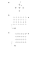
- FIG. 1A is a schematic diagram of an electron diffraction pattern corresponding to a region where there is no distortion and a region where the LiVOPO 4 crystal is not distorted
- FIG. 1B is a crystal structure where there is no distortion of the LiVOPO 4 crystal
- FIG. 1C is a schematic diagram of a distorted crystal structure (crystal lattice) of a LiVOPO 4 crystal.
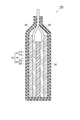
- FIG. 2 is a schematic cross-sectional view of a lithium ion secondary battery according to an embodiment of the present invention.
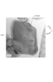
- FIG. 3 is a photograph of LiVOPO 4 crystal particles of Example 1 of the present invention taken with a transmission electron microscope (TEM).
- TEM transmission electron microscope
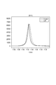
- Line Profile 1 in FIG. 5 shows the brightness of electron diffraction spots and 000 spots from the (011) plane and (0-1-1) plane of each electron diffraction pattern in the Center region and Left region in FIG.
- Line Profile 2 in FIG. 5 shows the brightness of the electron diffraction spots from the ( ⁇ 200) plane and the (200) plane of each electron diffraction pattern in the Center region and the Left region in FIG.
- FIG. 6 shows the brightness of the electron diffraction spot from the (011) plane in the electron diffraction pattern corresponding to the Center region in FIG.
- FIG. 3 shows the brightness from the (011) plane in the electron diffraction pattern corresponding to the Left region in FIG.
- 7 shows the brightness of the transmitted electron beam spot in the electron diffraction pattern corresponding to the center region of FIG. 3 and the brightness of the transmitted electron beam spot in the electron diffraction pattern corresponding to the Left region of FIG.
- FIG. 8 shows the brightness of the electron diffraction spot from the (0-1-1) plane in the electron diffraction pattern corresponding to the Center region in FIG. 3 and (0 in the electron diffraction pattern corresponding to the Left region in FIG.
- FIG. 11 is a diagram showing the luminance of an electron beam diffraction spot from the plane 1-1-1.
- FIG. 9 shows the brightness of the electron diffraction spot from the ( ⁇ 200) plane in the electron diffraction pattern corresponding to the Center region in FIG. 3 and the ( ⁇ 200) plane in the electron diffraction pattern corresponding to the Left region in FIG.
- FIG. 5 is a diagram in which the vertical axis represents the luminance of the electron beam diffraction spot and the horizontal axis represents the reciprocal of the surface spacing.
- FIG. 10 shows the brightness of the transmitted electron beam spot in the electron diffraction pattern corresponding to the Center region of FIG. 3 and the transmitted electron beam spot brightness in the electron diffraction pattern corresponding to the Left region of FIG. FIG.
- FIG. 11 shows the brightness of the electron diffraction spot from the (200) plane in the electron diffraction pattern corresponding to the Center region of FIG. 3 and the (200) plane from the (200) plane in the electron diffraction pattern corresponding to the Left region of FIG. It is a figure which shows the brightness
- the active material manufacturing method includes a first step, a second step, and a third step.
- a mixed solution containing a lithium source, a phosphate source, a vanadium source, and water is heated to 150 to 190 ° C. under pressure to generate a precursor in the mixed solution. That is, in the first step, the precursor is formed by a hydrothermal synthesis reaction.
- the pH of the mixed solution containing the precursor is adjusted to 6-8.
- the precursor is heated to 425 to 650 ° C. after the first step to generate an active material.
- LiVOPO 4 having a small and small crystal structure distortion and capable of improving the discharge capacity of the battery can be obtained.
- First step First, the above-described lithium source, phosphate source, vanadium source and water are put into a reaction vessel (for example, an autoclave) having a function of heating and pressurizing the inside, and these are dispersed and mixed. A liquid (aqueous solution) is prepared.
- a reaction vessel for example, an autoclave
- a liquid aqueous solution
- a mixture of a phosphate source, a vanadium source and water may be refluxed, and then a lithium source may be added thereto.
- a complex of a phosphate source and a vanadium source can be formed.
- you may add a reducing agent to a liquid mixture.
- pentavalent vanadium in the mixed solution is reduced, and tetravalent vanadium constituting LiVOPO 4 is easily generated.
- LiNO 3 Li 2 CO 3 , LiOH, LiCl, Li 2 SO 4, Li 3 PO 4 and CH 3 COOLi
- LiNO 3 LiNO 3
- Li 2 CO 3 LiOH, LiCl, Li 2 SO 4, Li 3 PO 4 and CH 3 COOLi
- the phosphoric acid source at least one selected from the group consisting of H 3 PO 4 , NH 4 H 2 PO 4 , (NH 4 ) 2 HPO 4 and Li 3 PO 4 can be used.
- At least one selected from the group consisting of V 2 O 5 and NH 4 VO 3 can be used.
- Two or more lithium sources, two or more phosphate sources, or two or more vanadium sources may be used in combination.
- reducing agent for example, at least one of hydrazine (NH 2 NH 2 .H 2 O) or hydrogen peroxide (H 2 O 2 ) can be used.
- hydrazine is preferably used. When hydrazine is used, the discharge capacity and rate characteristics of the battery tend to be remarkably improved as compared with the case where other reducing agents are used.
- the ratio [P] / the ratio of the number of moles of phosphorus element contained in the mixed solution [P] to the number of moles of vanadium element contained in the mixed solution [V] [V] is preferably adjusted to 0.9 to 1.2. Thereby, it becomes easy to improve the discharge capacity of the battery.
- [P] / [V] may be adjusted by the blending ratio of the phosphate source and the vanadium source contained in the mixed solution.
- the ratio [Li] / [V] of the number of moles of lithium element [Li] and [V] contained in the mixed solution is set to 0.9-1. It is preferable to adjust to 2. Thereby, it becomes easy to improve the discharge capacity of the battery.
- [Li] / [V] may be adjusted according to the blending ratio of the lithium source and the vanadium source contained in the mixed solution.
- the pH of the mixed solution may be adjusted before the mixed solution is heated under pressure.
- the pH of the mixed solution before the hydrothermal synthesis reaction is smaller, the ⁇ -type crystal phase of LiVOPO 4 tends to be generated, and the discharge capacity tends to be remarkably improved.
- an acidic reagent or a basic reagent is added to the mixed solution.
- the acidic reagent nitric acid, hydrochloric acid, sulfuric acid or the like may be used.
- an aqueous ammonia solution or the like may be used as the basic reagent.
- pH of a liquid mixture changes according to the quantity of a liquid mixture, the kind or compounding ratio of a lithium source, a phosphate source, and vanadium. Therefore, the addition amount of the acidic reagent and the basic reagent may be appropriately adjusted according to the amount of the mixed solution, the types of lithium source, phosphate source and vanadium source and the mixing ratio.
- the mixed liquid in the sealed reactor is heated while being pressurized.
- hydrothermal synthesis reaction is advanced in a liquid mixture.
- a precursor of LiVOPO 4 for example, a compound formed from a lithium source, a phosphate source or a vanadium source, or a crystal seed of LiVOPO 4 ) is hydrothermally synthesized.
- the mixed solution is heated to about 150 to 190 ° C. under pressure.
- the heating temperature of the mixed liquid hydroothermal synthesis reaction temperature
- the crystal structure of LiVOPO 4 finally obtained is distorted.
- the lower the heating temperature of the mixed solution the more likely the excessive crystal growth of the precursor is suppressed.
- the temperature of the mixed solution in the first step is too low, the precursor generation and crystal growth do not proceed sufficiently. As a result, the crystallinity of LiVOPO 4 finally obtained is lowered and the capacity density is reduced, so that it is difficult to improve the discharge capacity of the battery.
- the temperature of the mixed solution is too high, the crystal growth of the precursor proceeds excessively, and the Li diffusibility in the resulting LiVOPO 4 crystal decreases. Therefore, it becomes difficult to improve the discharge capacity and rate characteristics of the battery using LiVOPO 4 obtained.
- the temperature of a liquid mixture is too high, high heat resistance is calculated
- the pressure applied to the mixed solution in the first step is preferably 0.2 to 1 MPa. If the pressure applied to the mixed solution is too low, the crystallinity of LiVOPO 4 finally obtained tends to decrease, and the capacity density tends to decrease. If the pressure applied to the mixed solution is too high, the reaction vessel is required to have high pressure resistance, and the production cost of the active material tends to increase. By setting the pressure applied to the mixed solution within the above range, these tendencies can be suppressed. However, it is possible to synthesize the active material according to the present embodiment even when the pressure applied to the mixed liquid is outside the above numerical range.
- the time for heating the mixture under pressure is preferably more than 1 hour and 20 hours or less, and more preferably 2 hours or more and 18 hours or less. If the reaction time is too short, sufficient crystal nuclei cannot be formed and the capacity tends to decrease. If the reaction time is too long, crystal growth proceeds excessively, the particle size tends to increase, and the discharge capacity tends to decrease.
- the pH of the mixed solution containing the precursor is adjusted to 6-8. Thereby, a crystal of LiVOPO 4 having a small particle size on the nm scale and low distortion can be obtained. If the pH is too small, the particle size of the LiVOPO 4 obtained tends to increase and the discharge capacity tends to decrease. When the pH is too high, the proportion of ⁇ type crystals of LiVOPO 4 in the obtained active material increases, and the capacity tends to decrease.
- the pH adjustment method after the hydrothermal synthesis reaction is the same as the pH adjustment method performed before the hydrothermal synthesis reaction.
- the pH of the mixed solution containing the precursor can also be controlled within the range of 6 to 8 only by adjusting the pH of the mixed solution before the hydrothermal synthesis reaction.
- the mixture containing the precursor may be preheated at about 60 to 150 ° C. for about 1 to 30 hours before heating in the second step.
- Preheating removes excess water and organic solvent from the mixed solution, and a solid (powder) precursor can be obtained. As a result, it is possible to prevent impurities from being taken into LiVOPO 4 in the heat treatment step and to make the particle shape uniform.
- ⁇ Second step> After the first step, the precursor is heated in the second step (heat treatment step).
- the reaction of the lithium source, the phosphate source and the vanadium source that did not react in the first step can be advanced, or the crystal growth of LiVOPO 4 produced in the first step can be promoted.
- the precursor is heated to 425-650 ° C.
- the heating temperature (baking temperature) is too low, the crystal growth of LiVOPO 4 does not proceed sufficiently, and the capacity density becomes small.
- the heating temperature is too high, growth of the LiVOPO 4 proceeds excessively, the particle size of the LiVOPO 4 is increased. As a result, the diffusion of lithium in the active material is delayed, and the capacity density of the active material is reduced.
- the heat treatment temperature is outside the above range, it is difficult to improve the discharge capacity and rate characteristics of the battery.
- the heat treatment time of the precursor is preferably 3 to 20 hours.
- the heat treatment atmosphere is preferably a nitrogen atmosphere, an argon atmosphere, or an air atmosphere.
- Active material coarsely pulverized after the second step, carbon having a tap density of 0.03 to 0.09 g / ml, and carbon containing carbon having a tap density of 0.1 to 0.3 g / ml
- the material may be mixed and pulverized by planetary ball milling or the like.
- ⁇ -type LiVOPO 4 having a small crystal structure distortion can be obtained.
- the lithium-on diffusion path is less likely to bend and the lithium-on diffusion ability and insertion / desorption ability are improved as compared with conventional LiVOPO 4 with distortion.
- the discharge capacity is improved as compared with the conventional battery using LiVOPO 4 having distortion.
- the effect which concerns on this embodiment is not limited to said matter.
- the distortion of the crystal structure of LiVOPO 4 can be evaluated as follows. First, as shown in FIG. 1A, the electron diffraction pattern 2 at the reference location of the LiVOPO 4 crystal particle is measured. In addition, what is necessary is just to select the center part of a crystal grain without distortion as a reference location. Further, the electron diffraction pattern 4 is measured at an arbitrary target position (for example, the end side of the crystal particle) having a position different from the reference position in the LiVOPO 4 crystal particles. During this time, the set value of the optical system is not changed.
- the crystal structure 4a at the target location is reduced in the X direction with respect to the crystal structure 2a at the reference location, or Y It can be seen that it stretches in the direction.
- SAD limited-field diffraction
- NBD nano-beam diffraction
- a sample (LiVOPO 4 crystal particles) is irradiated with an incident electron beam in parallel to obtain a diffraction pattern consisting of dot-like spots, and a qualitative analysis of the crystal structure is performed.
- the location (diameter: several hundred nm) of the sample from which the diffraction pattern is obtained can be selected.
- the lattice constant, lattice type, crystal orientation, and strain at a specific location can be known.
- an electron beam is irradiated onto a sample (LiVOPO 4 crystal particles) in parallel to acquire an electron diffraction pattern, and then the electron beam is focused on the sample, and a nanometer-sized region (reference) using a small condenser aperture is used.
- This is a method for qualitative analysis of a crystal structure by irradiating a spot and a target spot. At this time, the diffraction spots have a disk shape corresponding to the convergence angle of the electron beam.
- the lattice constant, lattice type, and crystal orientation of the nanometer size region can be known.
- the observation region is determined by the limited field stop, whereas in the case of NBD, the observation region is determined by the convergence angle and the condenser stop.
- the strain in the ⁇ 100> direction in the ⁇ -type crystal of LiVOPO 4 can be controlled to 1.2% or less.
- a is the distance (unit: 1 / nm) between the diffraction spot on the ( ⁇ 200) plane and the diffraction spot on the (200) plane in the electron beam diffraction pattern of the reference location.
- b is the distance (1 / nm) between the diffraction spot on the ( ⁇ 200) plane and the diffraction spot on the (200) plane in the diffraction pattern of the target location.
- the distances a and b are distances in a reciprocal space (reciprocal numbers of crystal lattice plane spacings). That is, the distance between the diffraction spots of the electron diffraction pattern corresponds to the reciprocal of the interval between the crystal planes.
- the distance (unit: 1 / nm) between the diffraction spot on the (200) plane and the 000 spot (spot of transmission electron beam) matches the reciprocal of the plane spacing (unit: nm) on the (200) plane. Therefore, the strain ⁇ is the difference between the (200) plane and the ( ⁇ 200) plane distance (unit: nm) at the reference location of the LiVOPO 4 crystal particle, and the (200) plane and ( ⁇ 200) plane at the target location. It is a value corresponding to the change rate of the inter-surface distance (unit: nm).
- the average particle diameter of LiVOPO 4 crystal particles contained in the active material can be controlled to about 300 nm to 1 ⁇ m.
- the specific surface area increases and the lithium ion insertion / desorption ability tends to improve.
- the filling rate of the active material in the active material layer increases and the capacity density of the battery tends to increase.
- the lithium ion secondary battery 100 As shown in FIG. 2, the lithium ion secondary battery 100 according to the present embodiment is disposed adjacent to each other between the plate-like negative electrode 20 and the plate-like positive electrode 10 facing each other, and the negative electrode 20 and the positive electrode 10.
- a negative electrode lead 62 whose other end protrudes outside the case, and a positive electrode lead 60 whose one end is electrically connected to the positive electrode 10 and whose other end protrudes outside the case are provided. .
- the negative electrode 20 includes a negative electrode current collector 22 and a negative electrode active material layer 24 laminated on the negative electrode current collector 22.
- the positive electrode 10 includes a positive electrode current collector 12 and a positive electrode active material layer 14 stacked on the positive electrode current collector 12.
- the separator 18 is located between the negative electrode active material layer 24 and the positive electrode active material layer 14.
- the positive electrode active material layer 14 contains at least the active material according to the present embodiment and a conductive additive.
- the conductive aid include carbon materials such as carbon blacks, metal powders such as copper, nickel, stainless steel, and iron, a mixture of carbon materials and metal powders, and conductive oxides such as ITO.
- the carbon material preferably contains carbon having a tap density of 0.03 to 0.09 g / ml and carbon having a tap density of 0.1 to 0.3 g / ml.
- the positive electrode active material layer may include a binder that binds the active material and the conductive additive.
- the positive electrode active material layer 14 is formed by a step of applying a paint including LiVOPO 4 obtained by the manufacturing method according to the present embodiment, a binder, a solvent, and a conductive additive on the positive electrode current collector 12.
- Examples of the negative electrode active material included in the negative electrode active material layer 24 include carbon materials such as natural graphite, artificial graphite, non-graphitizable carbon, graphitizable carbon, and low-temperature calcined carbon, and lithium such as Al, Si, Sn, and Si.
- the negative electrode active material may be bound by a binder.
- the negative electrode active material layer 24 is formed by a step of applying a paint containing a negative electrode active material or the like on the negative electrode current collector 22.
- carbon particles may be added to the mixture before heating.
- LiVOPO 4 is generated on the surface of the carbon particles, and the LiVOPO 4 can be supported on the carbon particles.
- the material constituting the carbon particles include carbon black (graphite) such as ketjen black and acetylene black, activated carbon, hard carbon, and soft carbon.
- the active material of the present invention can also be used as an electrode material for electrochemical elements other than lithium ion secondary batteries.
- an electrochemical element other than a lithium ion secondary battery such as a metal lithium secondary battery (an electrode containing an active material obtained by the present invention is used as a cathode and metal lithium is used as an anode).
- Examples include secondary batteries and electrochemical capacitors such as lithium capacitors.
- These electrochemical elements can be used for power sources such as self-propelled micromachines and IC cards, and distributed power sources arranged on or in a printed circuit board.
- Example 1 First step> In the production of the active material of Example 1, a mixed solution containing the following raw materials was prepared.
- the amount of each raw material charged is approximately 33.78 g stoichiometrically when converted to LiVOPO 4 (molecular weight: 168.85). This corresponds to a yield of (0.2 mol) LiVOPO 4 .
- the above mixture was prepared by the following procedure. First, the above H 3 PO 4 and distilled water were put into a 500 mL autoclave inner cylinder, and these were stirred with a magnetic stirrer. Then, when the autoclave tube was continued for about 2.5 hours with stirring after the addition of V 2 O 5 of the above, to obtain a liquid phase yellowish orange (suspension) into the flask.
- the hydrazine monohydrate (NH 2 NH 2 .H 2 O) was added dropwise to the liquid phase while stirring the liquid phase with a magnetic stirrer. When hydrazine monohydrate was added dropwise, the liquid phase changed from yellow orange to dull green. Hydrazine monohydrate was added dropwise, and then the above LiOH.H 2 O was added to the liquid phase over 10 minutes. The pH of the liquid phase immediately after addition of LiOH.H 2 O was 7-8.
- the above mixture was obtained by the above procedure.
- the autoclave inner cylinder containing the above mixture was sealed, and the mixture was heated under predetermined PID control while stirring the mixture with a strong magnetic stirrer.
- the internal pressure in the sealed glass container was increased with heating.
- the hydrothermal synthesis reaction was allowed to proceed in the autoclave inner cylinder.
- the mixed solution in the glass container was heated under pressure for 16 hours.
- the temperature in the glass container was maintained at 160 ° C.
- the pressure in the glass container was kept at 0.6 MPa.
- the mixed solution was taken out from the autoclave inner cylinder after the temperature in the autoclave inner cylinder dropped to 40 ° C. It took about 4 hours for the temperature in the autoclave inner cylinder to drop to 40 ° C. after the heating was stopped.
- the mixed liquid taken out from the inner cylinder of the autoclave was a light blue paste.
- the pH of the mixed solution after the first step was adjusted to 7.
- the mixed solution was dried at 90 ° C. for 32 hours to obtain 38.27 g of a light blue solid as a precursor. An oven was used for drying. The precursor was ground with a commercial coffee mill.
- ⁇ Second step> of the pulverized precursor 3.00 g was placed in an alumina crucible.
- a second step (heat treatment step) for heating the precursor in the alumina crucible using a heating furnace was performed.
- the precursor was heated in an air atmosphere.
- the temperature in the furnace was raised from room temperature to 600 ° C. over 60 minutes, the solid in the alumina crucible was heated at 600 ° C. for 4 hours, and then the heating furnace was naturally cooled.
- 2.550 g of yellowish green powder was obtained as the active material of Example 1.
- the residual ratio of the solid after the heat treatment step was 85.0% by weight.
- Example 2 to 7 and Comparative Examples 1 to 4 the temperature in the glass container in the first step (temperature of hydrothermal synthesis reaction) was adjusted to the values shown in Table 1.
- the temperature in the furnace (heat treatment temperature) in the heat treatment step was adjusted to the values shown in Table 1. Except for the above items, active materials of Examples 2 to 7 and Comparative Examples 1 to 4 were obtained in the same manner as in Example 1.
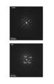
- FIG. 4 shows an electron diffraction pattern in each region.
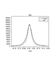
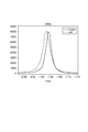
- 5 to 11 show line profiles of diffraction spots of crystal orientations of electron diffraction patterns in the center region and the left region.
- the horizontal axis in FIGS. 5 to 11 corresponds to the distance between spots (distance in the inverse space) in each electron diffraction pattern of FIG.
- the numerical value on the horizontal axis is a value based on the peak position (000 spots) of the luminance of the electron beam transmitted through the crystal particles as the reference (origin 0), and is the reciprocal of the crystal plane spacing.
- the vertical axis represents the intensity (luminance) of the electron beam.
- the strain ⁇ in the ⁇ 100> direction of the ⁇ -type crystal particles of LiVOPO 4 of Example 1 was calculated. Note that the strain ⁇ is an average value of 20 crystal grains.
- Example 1 In the same manner as in Example 1, the strain ⁇ in the ⁇ 100> direction of the LiVOPO 4 ⁇ -type crystal particles of each Example and each Comparative Example was calculated. Table 1 shows the distortion of each example and each comparative example.
- Example 1 The active material of Example 1, acetylene black (FX-35 manufactured by Denki Kagaku Kogyo) and ketjen black (EC600JD manufactured by Ketchen Black International) were weighed at a weight ratio of 80: 5: 5. On the other hand, the mixing process for 1 minute by the planetary ball mill was performed 3 times. The rotation speed of the planetary ball mill was set to 550 rpm. A mixture of the resulting mixture and polyvinylidene fluoride (PVDF, Kureha Kagaku KF7305) as a binder was dispersed in N-methyl-2-pyrrolidone (NMP) as a solvent to prepare a slurry.
- PVDF polyvinylidene fluoride
- the weight ratio of the mixture and PVDF in the slurry was adjusted to 90:10. This slurry was applied onto an aluminum foil as a current collector, dried, and then rolled to obtain an electrode (positive electrode) on which an active material layer containing the active material of Example 1 was formed.
- the obtained electrode and the Li foil as the counter electrode were laminated with a separator made of a polyethylene microporous film interposed therebetween to obtain a laminated body (element body).
- This laminate is placed in an aluminum laminator pack, and 1M EC / DEC (volume ratio 30:70) is injected into the aluminum laminate pack as an electrolytic solution, followed by vacuum sealing to produce an evaluation cell of Example 1. did.
- Electron diffraction pattern at reference location 4 ... Electron diffraction pattern at target location, 2a ... Crystal structure at reference location, 4a ... Crystal structure at target location, 10 ... Positive electrode, 20 ... negative electrode, 12 ... positive electrode current collector, 14 ... positive electrode active material layer, 18 ... separator, 22 ... negative electrode current collector, 24 ... negative electrode active material layer, 30. .. Power generation element, 50... Case, 60, 62... Lead, 100.
Landscapes
- Chemical & Material Sciences (AREA)
- Chemical Kinetics & Catalysis (AREA)
- Electrochemistry (AREA)
- General Chemical & Material Sciences (AREA)
- Engineering & Computer Science (AREA)
- Inorganic Chemistry (AREA)
- Manufacturing & Machinery (AREA)
- Materials Engineering (AREA)
- Organic Chemistry (AREA)
- Crystallography & Structural Chemistry (AREA)
- Battery Electrode And Active Subsutance (AREA)
Abstract
Description
以下では、本発明の一実施形態に係る活物質の製造方法について説明する。本実施形態に係る活物質の製造方法は、第一工程、第二工程及び第三工程を備える。第一工程では、リチウム源とリン酸源とバナジウム源と水とを含む混合液を加圧下で150~190℃に加熱して、混合液中に前駆体を生成させる。つまり、第一工程では、水熱合成反応により前駆体を形成する。また、第一工程では、前駆体を含む混合液のpHを6~8に調整する。第二工程では、第一工程後に前駆体を425~650℃に加熱して活物質を生成させる。
第一工程では、まず、内部を加熱、加圧する機能を有する反応容器(例えば、オートクレーブ等)内に、上述したリチウム源、リン酸源、バナジウム源及び水を投入して、これらが分散した混合液(水溶液)を調製する。
第一工程後、第二工程(熱処理工程)では前駆体を加熱する。第二工程によって、第一工程で反応しなかったリチウム源、リン酸源及びバナジウム源の反応を進行させたり、第一工程で生成したLiVOPO4の結晶成長を促進したりすることができる。
本実施形態に係る活物質の製造方法によれば、結晶構造の歪みの小さいβ型のLiVOPO4を得ることができる。結晶構造(格子骨格)の歪みが小さいLiVOPO4内では、従来の歪みのあるLiVOPO4に比べて、リチウムオンの拡散経路が屈曲し難く、リチウムオンの拡散能及び挿入・脱離能が向上する。これにより、本実施形態の活物質を正極に用いたリチウムイオン二次電池では従来の歪みのあるLiVOPO4を用いた電池に比べて、放電容量が向上する。ただし、本実施形態に係る作用効果は、上記の事項に限定されるものではない。
α={(a-b)/a}×100 (1)
回折スポットと(200)面の回折スポットとの距離(単位:1/nm)である。bは、目的箇所の回折パターンにおける(-200)面の回折スポットと(200)面の回折スポットとの距離(1/nm)である。ここで、距離a,bとは、逆空間における距離(結晶格子の面間隔の逆数)である。つまり、電子線回折図形の回折スポット間の距離は、結晶面の間隔の逆数に対応する。例えば、(200)面の回折スポットと000スポット(透過電子線のスポット)との間隔(単位:1/nm)は、(200)面の面間隔(単位:nm)の逆数と一致する。よって、歪みαは、LiVOPO4の結晶粒子のリファレンス箇所における(200)面及び(-200)面の面間距離(単位:nm)に対する、目的箇所における(200)面及び(-200)面の面間距離(単位:nm)の変化率に対応する値である。
図2に示すように、本実施形態に係るリチウムイオン二次電池100は、互いに対向する板状の負極20及び板状の正極10と、負極20と正極10との間に隣接して配置される板状のセパレータ18と、を備える発電要素30と、リチウムイオンを含む電解質溶液と、これらを密閉した状態で収容するケース50と、負極20に一方の端部が電気的に接続されると共に他方の端部がケースの外部に突出される負極リード62と、正極10に一方の端部が電気的に接続されると共に他方の端部がケースの外部に突出される正極リード60とを備える。
<第一工程>
実施例1の活物質の製造では、以下の原料を含む混合液を調製した。
5.81、ナカライテスク社製)。
)。なお、ガラス容器とオートクレーブとの間に別途20gの蒸留水も用いた。
粉砕後の前駆体のうち3.00gをアルミナ坩堝に入れた。加熱炉を用いてアルミナ坩堝内の前駆体を加熱する第二工程(熱処理工程)を実施した。熱処理工程では、空気雰囲気中で前駆体を加熱した。また、熱処理工程では、炉内の温度を60分かけて室温から600℃まで昇温させ、アルミナ坩堝内の固体を600℃で4時間加熱した後、加熱炉を自然冷却した。この熱処理工程により、実施例1の活物質として、黄緑色の粉体2.550gを得た。熱処理工程後の固体の残存率は85.0重量%であった。
実施例2~7及び比較例1~4では、第一工程におけるガラス容器内の温度(水熱合成反応の温度)を表1に示す値に調整した。実施例2~7及び比較例1~4では、熱処理工程における炉内の温度(熱処理温度)を表1に示す値に調整した。以上の事項以外は、実施例1と同様の方法で、実施例2~7及び比較例1~4の各活物質を得た。
粉末X線回折(XRD)による解析の結果、全実施例及び全比較例の各活物質は、LiVOPO4のβ型結晶粒子であることが確認された。透過型電子顕微鏡(TEM)により、実施例1のLiVOPO4の結晶粒子20個について、各粒子の最大径を測定して、その平均値(平均粒子径)を算出した。他の実施例及び比較例についても、実施例1と同様の方法で、平均粒子径を求めた。各実施例及び各比較例の平均粒子径を表1に示す。
TEMにより実施例1のLiVOPO4の結晶粒子の写真を撮影した。写真を図3に示す。図3に示す結晶粒子のCenter領域(リファレンス箇所)及びLeft領域(目的箇所)における電子線回折パターンをそれぞれ撮影した。各領域における電子線回折パターンを図4に示す。Center領域及びLeft領域の各電子線回折パターンの各結晶方位の回折スポットのラインプロファイルを図5~11に示す。図5~11の横軸は、図4の各電子線回折パターンにおけるスポット間の距離(逆空間における距離)に対応する。横軸の数値は、結晶粒子を透過した電子線の輝度のピーク位置(000スポット)を基準(原点0)とした値であり、結晶の面間隔の逆数である。縦軸は、電子線の強度(輝度)を意味する。電子線回折パターンの撮影は、SADにより行った。また、Center領域及びLeft領域の各電子線回折の入射電子線の方位は[01-1]に調整した。
実施例1の活物質と、アセチレンブラック(電気化学工業製FX-35)と、ケッチェンブラック(ケッチェンブラックインターナショナル社製EC600JD)とを、80:5:5の重量比で秤量し、これに対して遊星型ボールミルによる1分間の混合処理を3回行った。遊星型ボールミルの回転数は550rpmに設定した。これにより得た混合物とバインダーであるポリフッ化ビニリデン(PVDF、呉羽化学製KF7305)とを混合したものを、溶媒であるN-メチル-2-ピロリドン(NMP)中に分散させてスラリーを調製した。なお、スラリー中における混合物とPVDFとの重量比を90:10に調整した。このスラリーを集電体であるアルミニウム箔上に塗布し、乾燥させた後、圧延を行い、実施例1の活物質を含む活物質層が形成された電極(正極)を得た。
実施例1の評価用セルを用いて、放電レートを0.1C(25℃で定電流放電を行ったときに10時間で放電終了となる電流値)とした場合の放電容量(単位:mAh/g)を測定した。測定結果を表1に示す。放電容量の測定における電流密度は16~160mA/g(1C=160mA/g)であり、電圧範囲は2.8~4.3Vであった。

Claims (6)
- リチウム源とリン酸源とバナジウム源と水とを含む混合液を加圧下で150~190℃に加熱して、前記混合液中に前駆体を生成させ、且つ前記前駆体を含む前記混合液のpHを6~8に調整する第一工程と、
前記第一工程後に、前記前駆体を425~650℃に加熱して活物質を生成させる第二工程と、
を備える、
活物質の製造方法。 - 請求項1に記載の製造方法により得た活物質と、バインダーと、溶媒と、導電助剤と、を含む塗料を集電体上に塗布して、前記集電体と前記集電体上に積層された活物質層とを有する電極を作製する工程を備える、
リチウムイオン二次電池の製造方法。 - LiVOPO4のβ型結晶を含み、前記β型結晶内の<100>方向の歪みが1.2%以下である、活物質。
- 集電体と前記集電体上に積層された活物質層とを備え、
前記活物質層は請求項3に記載の活物質を含む、
電極。 - 前記活物質層は、タップ密度が0.03~0.09g/mlであるカーボンと、タップ密度が0.1~0.3g/mlであるカーボンと、を更に含む、
請求項4に記載の電極。 - 請求項4又は5に記載の電極を備える、
リチウムイオン二次電池。
Priority Applications (2)
| Application Number | Priority Date | Filing Date | Title |
|---|---|---|---|
| CN201280016818.1A CN103493262B (zh) | 2011-03-31 | 2012-03-30 | 活性物质、活性物质的制造方法、电极、锂离子二次电池以及锂离子二次电池的制造方法 |
| US14/005,357 US10611639B2 (en) | 2011-03-31 | 2012-03-30 | Active material, method for manufacturing active material, electrode, lithium ion secondary battery, and method for manufacturing lithium ion secondary battery |
Applications Claiming Priority (2)
| Application Number | Priority Date | Filing Date | Title |
|---|---|---|---|
| JP2011-080137 | 2011-03-31 | ||
| JP2011080137A JP5741143B2 (ja) | 2011-03-31 | 2011-03-31 | 活物質、活物質の製造方法、電極、リチウムイオン二次電池及びリチウムイオン二次電池の製造方法 |
Publications (1)
| Publication Number | Publication Date |
|---|---|
| WO2012133731A1 true WO2012133731A1 (ja) | 2012-10-04 |
Family
ID=46931429
Family Applications (1)
| Application Number | Title | Priority Date | Filing Date |
|---|---|---|---|
| PCT/JP2012/058508 Ceased WO2012133731A1 (ja) | 2011-03-31 | 2012-03-30 | 活物質、活物質の製造方法、電極、リチウムイオン二次電池及びリチウムイオン二次電池の製造方法 |
Country Status (4)
| Country | Link |
|---|---|
| US (1) | US10611639B2 (ja) |
| JP (1) | JP5741143B2 (ja) |
| CN (1) | CN103493262B (ja) |
| WO (1) | WO2012133731A1 (ja) |
Cited By (2)
| Publication number | Priority date | Publication date | Assignee | Title |
|---|---|---|---|---|
| JP2014139922A (ja) * | 2012-12-17 | 2014-07-31 | Tdk Corp | 正極活物質及びリチウムイオン二次電池 |
| WO2016175311A1 (ja) * | 2015-04-30 | 2016-11-03 | 三井金属鉱業株式会社 | 5v級スピネル型リチウムマンガン含有複合酸化物 |
Families Citing this family (6)
| Publication number | Priority date | Publication date | Assignee | Title |
|---|---|---|---|---|
| WO2014167178A1 (en) * | 2013-04-08 | 2014-10-16 | Nokia Corporation | Method and technical equipment for video encoding and decoding |
| JP6098382B2 (ja) * | 2013-06-07 | 2017-03-22 | Tdk株式会社 | 正極活物質及びリチウムイオン二次電池 |
| JP6197609B2 (ja) * | 2013-11-29 | 2017-09-20 | Tdk株式会社 | 正極活物質、正極及びリチウムイオン二次電池 |
| JP6349825B2 (ja) * | 2014-03-20 | 2018-07-04 | Tdk株式会社 | 正極及びそれを用いたリチウムイオン二次電池 |
| CN107845783B (zh) * | 2017-09-15 | 2020-07-14 | 深圳市德方纳米科技股份有限公司 | 纳米磷酸氧钒锂正极材料及其制备方法、锂离子电池 |
| US11251430B2 (en) | 2018-03-05 | 2022-02-15 | The Research Foundation For The State University Of New York | ϵ-VOPO4 cathode for lithium ion batteries |
Citations (4)
| Publication number | Priority date | Publication date | Assignee | Title |
|---|---|---|---|---|
| JP2007317583A (ja) * | 2006-05-29 | 2007-12-06 | Hitachi Vehicle Energy Ltd | リチウム二次電池 |
| JP2010218822A (ja) * | 2009-03-16 | 2010-09-30 | Tdk Corp | 活物質の製造方法、活物質、電極及びリチウムイオン二次電池 |
| JP2010218830A (ja) * | 2009-03-16 | 2010-09-30 | Tdk Corp | 活物質、これを含む電極、当該電極を含むリチウムイオン二次電池、及び活物質の製造方法 |
| JP2011054559A (ja) * | 2009-08-04 | 2011-03-17 | Sumitomo Chemical Co Ltd | 正極用粉末および正極合剤 |
Family Cites Families (8)
| Publication number | Priority date | Publication date | Assignee | Title |
|---|---|---|---|---|
| JP5002098B2 (ja) | 2001-08-30 | 2012-08-15 | 祐作 滝田 | 非水電解質二次電池用電極活物質、それを含む電極及び電池 |
| JP4314859B2 (ja) | 2003-03-31 | 2009-08-19 | 祐作 滝田 | 非水電解質二次電池用電極活物質、非水電解質二次電池用電極及び非水電解質二次電池 |
| KR100599602B1 (ko) * | 2004-10-28 | 2006-07-13 | 삼성에스디아이 주식회사 | 리튬 이차 전지용 양극 및 이를 포함하는 리튬 이차 전지 |
| US20100233545A1 (en) | 2009-03-16 | 2010-09-16 | Tdk Corporation | Active material, method of manufacturing active material, electrode, and lithium-ion secondary battery |
| JP5347603B2 (ja) * | 2009-03-16 | 2013-11-20 | Tdk株式会社 | 活物質の製造方法、活物質、電極及びリチウムイオン二次電池 |
| JP5444944B2 (ja) * | 2009-08-25 | 2014-03-19 | Tdk株式会社 | 活物質及び活物質の製造方法 |
| US20110052995A1 (en) * | 2009-08-28 | 2011-03-03 | Tdk Corporation | Active material, electrode containing the same, lithium secondary battery provided therewith and method for manufacture of the active material |
| JP5375446B2 (ja) * | 2009-08-28 | 2013-12-25 | Tdk株式会社 | 活物質、これを含む電極、当該電極を備えるリチウム二次電池、及び活物質の製造方法 |
-
2011
- 2011-03-31 JP JP2011080137A patent/JP5741143B2/ja active Active
-
2012
- 2012-03-30 CN CN201280016818.1A patent/CN103493262B/zh active Active
- 2012-03-30 WO PCT/JP2012/058508 patent/WO2012133731A1/ja not_active Ceased
- 2012-03-30 US US14/005,357 patent/US10611639B2/en active Active
Patent Citations (4)
| Publication number | Priority date | Publication date | Assignee | Title |
|---|---|---|---|---|
| JP2007317583A (ja) * | 2006-05-29 | 2007-12-06 | Hitachi Vehicle Energy Ltd | リチウム二次電池 |
| JP2010218822A (ja) * | 2009-03-16 | 2010-09-30 | Tdk Corp | 活物質の製造方法、活物質、電極及びリチウムイオン二次電池 |
| JP2010218830A (ja) * | 2009-03-16 | 2010-09-30 | Tdk Corp | 活物質、これを含む電極、当該電極を含むリチウムイオン二次電池、及び活物質の製造方法 |
| JP2011054559A (ja) * | 2009-08-04 | 2011-03-17 | Sumitomo Chemical Co Ltd | 正極用粉末および正極合剤 |
Cited By (5)
| Publication number | Priority date | Publication date | Assignee | Title |
|---|---|---|---|---|
| JP2014139922A (ja) * | 2012-12-17 | 2014-07-31 | Tdk Corp | 正極活物質及びリチウムイオン二次電池 |
| US9825295B2 (en) | 2012-12-17 | 2017-11-21 | Tdk Corporation | Positive electrode active material and lithium-ion secondary battery |
| WO2016175311A1 (ja) * | 2015-04-30 | 2016-11-03 | 三井金属鉱業株式会社 | 5v級スピネル型リチウムマンガン含有複合酸化物 |
| JPWO2016175311A1 (ja) * | 2015-04-30 | 2018-02-22 | 三井金属鉱業株式会社 | 5v級スピネル型リチウムマンガン含有複合酸化物 |
| US10446842B2 (en) | 2015-04-30 | 2019-10-15 | Mitsui Mining & Smelting Co., Ltd. | 5V-class spinel-type lithium-manganese-containing composite oxide |
Also Published As
| Publication number | Publication date |
|---|---|
| CN103493262B (zh) | 2016-04-06 |
| US10611639B2 (en) | 2020-04-07 |
| CN103493262A (zh) | 2014-01-01 |
| US20140004416A1 (en) | 2014-01-02 |
| JP2012216377A (ja) | 2012-11-08 |
| JP5741143B2 (ja) | 2015-07-01 |
Similar Documents
| Publication | Publication Date | Title |
|---|---|---|
| US9269954B2 (en) | Production process for lithium-silicate-system compound | |
| JP5741143B2 (ja) | 活物質、活物質の製造方法、電極、リチウムイオン二次電池及びリチウムイオン二次電池の製造方法 | |
| EP2407426A1 (en) | Process for producing lithium borate compound | |
| JP5165515B2 (ja) | リチウムイオン二次電池 | |
| JP5365126B2 (ja) | リチウムイオン二次電池の正極用活物質及びリチウムイオン二次電池の正極用活物質の製造方法 | |
| JP5347603B2 (ja) | 活物質の製造方法、活物質、電極及びリチウムイオン二次電池 | |
| WO2010109869A1 (ja) | リチウムイオン電池用正極活物質の製造方法とリチウムイオン電池用正極活物質及びリチウムイオン電池用電極並びにリチウムイオン電池 | |
| JP2009218205A (ja) | リチウム二次電池用正極活物質、リチウム二次電池用正極及びリチウム二次電池、並びに、その製造方法 | |
| JP5810587B2 (ja) | リチウムイオン二次電池用活物質、リチウムイオン二次電池用電極、リチウムイオン二次電池 | |
| JP5365125B2 (ja) | リチウムイオン二次電池の正極用活物質 | |
| JP5515343B2 (ja) | 活物質の製造方法、活物質、電極及びリチウムイオン二次電池 | |
| JP6345227B2 (ja) | リン酸バナジウムリチウムの製造方法 | |
| JP5444944B2 (ja) | 活物質及び活物質の製造方法 | |
| JP2012004046A (ja) | 活物質の製造方法、活物質及びリチウムイオン二次電池 | |
| JP5888046B2 (ja) | 正極活物質、正極及びリチウムイオン二次電池 | |
| JP2012004045A (ja) | 活物質の製造方法、活物質及びリチウムイオン二次電池 | |
| JP5444942B2 (ja) | 活物質の製造方法 | |
| JP5444943B2 (ja) | 活物質の製造方法 | |
| JP7144785B2 (ja) | リン酸バナジウムリチウムの製造方法 | |
| JP6164422B2 (ja) | 正極活物質、正極及びリチウムイオン二次電池 | |
| JP6197610B2 (ja) | 正極活物質、正極及びリチウムイオン二次電池 | |
| WO2017154690A1 (ja) | リン酸バナジウムリチウムの製造方法 |
Legal Events
| Date | Code | Title | Description |
|---|---|---|---|
| WWE | Wipo information: entry into national phase |
Ref document number: 201280016818.1 Country of ref document: CN |
|
| 121 | Ep: the epo has been informed by wipo that ep was designated in this application |
Ref document number: 12765755 Country of ref document: EP Kind code of ref document: A1 |
|
| WWE | Wipo information: entry into national phase |
Ref document number: 14005357 Country of ref document: US |
|
| NENP | Non-entry into the national phase |
Ref country code: DE |
|
| 122 | Ep: pct application non-entry in european phase |
Ref document number: 12765755 Country of ref document: EP Kind code of ref document: A1 |