WO2012133526A1 - 排気ガス浄化触媒、排気ガス浄化モノリス触媒及び排気ガス浄化触媒の製造方法 - Google Patents
排気ガス浄化触媒、排気ガス浄化モノリス触媒及び排気ガス浄化触媒の製造方法 Download PDFInfo
- Publication number
- WO2012133526A1 WO2012133526A1 PCT/JP2012/058122 JP2012058122W WO2012133526A1 WO 2012133526 A1 WO2012133526 A1 WO 2012133526A1 JP 2012058122 W JP2012058122 W JP 2012058122W WO 2012133526 A1 WO2012133526 A1 WO 2012133526A1
- Authority
- WO
- WIPO (PCT)
- Prior art keywords
- exhaust gas
- oxide
- gas purification
- purification catalyst
- carboxylic acid
- Prior art date
- Legal status (The legal status is an assumption and is not a legal conclusion. Google has not performed a legal analysis and makes no representation as to the accuracy of the status listed.)
- Ceased
Links
Images





Classifications
-
- B—PERFORMING OPERATIONS; TRANSPORTING
- B01—PHYSICAL OR CHEMICAL PROCESSES OR APPARATUS IN GENERAL
- B01J—CHEMICAL OR PHYSICAL PROCESSES, e.g. CATALYSIS OR COLLOID CHEMISTRY; THEIR RELEVANT APPARATUS
- B01J23/00—Catalysts comprising metals or metal oxides or hydroxides, not provided for in group B01J21/00
- B01J23/70—Catalysts comprising metals or metal oxides or hydroxides, not provided for in group B01J21/00 of the iron group metals or copper
- B01J23/76—Catalysts comprising metals or metal oxides or hydroxides, not provided for in group B01J21/00 of the iron group metals or copper combined with metals, oxides or hydroxides provided for in groups B01J23/02 - B01J23/36
- B01J23/84—Catalysts comprising metals or metal oxides or hydroxides, not provided for in group B01J21/00 of the iron group metals or copper combined with metals, oxides or hydroxides provided for in groups B01J23/02 - B01J23/36 with arsenic, antimony, bismuth, vanadium, niobium, tantalum, polonium, chromium, molybdenum, tungsten, manganese, technetium or rhenium
- B01J23/889—Manganese, technetium or rhenium
- B01J23/8892—Manganese
-
- B—PERFORMING OPERATIONS; TRANSPORTING
- B01—PHYSICAL OR CHEMICAL PROCESSES OR APPARATUS IN GENERAL
- B01D—SEPARATION
- B01D53/00—Separation of gases or vapours; Recovering vapours of volatile solvents from gases; Chemical or biological purification of waste gases, e.g. engine exhaust gases, smoke, fumes, flue gases, aerosols
- B01D53/34—Chemical or biological purification of waste gases
- B01D53/92—Chemical or biological purification of waste gases of engine exhaust gases
- B01D53/94—Chemical or biological purification of waste gases of engine exhaust gases by catalytic processes
- B01D53/9445—Simultaneously removing carbon monoxide, hydrocarbons or nitrogen oxides making use of three-way catalysts [TWC] or four-way-catalysts [FWC]
- B01D53/945—Simultaneously removing carbon monoxide, hydrocarbons or nitrogen oxides making use of three-way catalysts [TWC] or four-way-catalysts [FWC] characterised by a specific catalyst
-
- B—PERFORMING OPERATIONS; TRANSPORTING
- B01—PHYSICAL OR CHEMICAL PROCESSES OR APPARATUS IN GENERAL
- B01J—CHEMICAL OR PHYSICAL PROCESSES, e.g. CATALYSIS OR COLLOID CHEMISTRY; THEIR RELEVANT APPARATUS
- B01J21/00—Catalysts comprising the elements, oxides, or hydroxides of magnesium, boron, aluminium, carbon, silicon, titanium, zirconium, or hafnium
- B01J21/06—Silicon, titanium, zirconium or hafnium; Oxides or hydroxides thereof
- B01J21/066—Zirconium or hafnium; Oxides or hydroxides thereof
-
- B—PERFORMING OPERATIONS; TRANSPORTING
- B01—PHYSICAL OR CHEMICAL PROCESSES OR APPARATUS IN GENERAL
- B01J—CHEMICAL OR PHYSICAL PROCESSES, e.g. CATALYSIS OR COLLOID CHEMISTRY; THEIR RELEVANT APPARATUS
- B01J23/00—Catalysts comprising metals or metal oxides or hydroxides, not provided for in group B01J21/00
- B01J23/002—Mixed oxides other than spinels, e.g. perovskite
-
- B—PERFORMING OPERATIONS; TRANSPORTING
- B01—PHYSICAL OR CHEMICAL PROCESSES OR APPARATUS IN GENERAL
- B01J—CHEMICAL OR PHYSICAL PROCESSES, e.g. CATALYSIS OR COLLOID CHEMISTRY; THEIR RELEVANT APPARATUS
- B01J23/00—Catalysts comprising metals or metal oxides or hydroxides, not provided for in group B01J21/00
- B01J23/10—Catalysts comprising metals or metal oxides or hydroxides, not provided for in group B01J21/00 of rare earths
-
- B—PERFORMING OPERATIONS; TRANSPORTING
- B01—PHYSICAL OR CHEMICAL PROCESSES OR APPARATUS IN GENERAL
- B01J—CHEMICAL OR PHYSICAL PROCESSES, e.g. CATALYSIS OR COLLOID CHEMISTRY; THEIR RELEVANT APPARATUS
- B01J23/00—Catalysts comprising metals or metal oxides or hydroxides, not provided for in group B01J21/00
- B01J23/16—Catalysts comprising metals or metal oxides or hydroxides, not provided for in group B01J21/00 of arsenic, antimony, bismuth, vanadium, niobium, tantalum, polonium, chromium, molybdenum, tungsten, manganese, technetium or rhenium
- B01J23/32—Manganese, technetium or rhenium
- B01J23/34—Manganese
-
- B—PERFORMING OPERATIONS; TRANSPORTING
- B01—PHYSICAL OR CHEMICAL PROCESSES OR APPARATUS IN GENERAL
- B01J—CHEMICAL OR PHYSICAL PROCESSES, e.g. CATALYSIS OR COLLOID CHEMISTRY; THEIR RELEVANT APPARATUS
- B01J23/00—Catalysts comprising metals or metal oxides or hydroxides, not provided for in group B01J21/00
- B01J23/70—Catalysts comprising metals or metal oxides or hydroxides, not provided for in group B01J21/00 of the iron group metals or copper
- B01J23/76—Catalysts comprising metals or metal oxides or hydroxides, not provided for in group B01J21/00 of the iron group metals or copper combined with metals, oxides or hydroxides provided for in groups B01J23/02 - B01J23/36
- B01J23/83—Catalysts comprising metals or metal oxides or hydroxides, not provided for in group B01J21/00 of the iron group metals or copper combined with metals, oxides or hydroxides provided for in groups B01J23/02 - B01J23/36 with rare earths or actinides
-
- B—PERFORMING OPERATIONS; TRANSPORTING
- B01—PHYSICAL OR CHEMICAL PROCESSES OR APPARATUS IN GENERAL
- B01J—CHEMICAL OR PHYSICAL PROCESSES, e.g. CATALYSIS OR COLLOID CHEMISTRY; THEIR RELEVANT APPARATUS
- B01J37/00—Processes, in general, for preparing catalysts; Processes, in general, for activation of catalysts
- B01J37/02—Impregnation, coating or precipitation
- B01J37/0201—Impregnation
-
- F—MECHANICAL ENGINEERING; LIGHTING; HEATING; WEAPONS; BLASTING
- F01—MACHINES OR ENGINES IN GENERAL; ENGINE PLANTS IN GENERAL; STEAM ENGINES
- F01N—GAS-FLOW SILENCERS OR EXHAUST APPARATUS FOR MACHINES OR ENGINES IN GENERAL; GAS-FLOW SILENCERS OR EXHAUST APPARATUS FOR INTERNAL-COMBUSTION ENGINES
- F01N3/00—Exhaust or silencing apparatus having means for purifying, rendering innocuous, or otherwise treating exhaust
- F01N3/08—Exhaust or silencing apparatus having means for purifying, rendering innocuous, or otherwise treating exhaust for rendering innocuous
- F01N3/10—Exhaust or silencing apparatus having means for purifying, rendering innocuous, or otherwise treating exhaust for rendering innocuous by thermal or catalytic conversion of noxious components of exhaust
- F01N3/24—Exhaust or silencing apparatus having means for purifying, rendering innocuous, or otherwise treating exhaust for rendering innocuous by thermal or catalytic conversion of noxious components of exhaust characterised by constructional aspects of converting apparatus
- F01N3/28—Construction of catalytic reactors
- F01N3/2803—Construction of catalytic reactors characterised by structure, by material or by manufacturing of catalyst support
- F01N3/2825—Ceramics
- F01N3/2828—Ceramic multi-channel monoliths, e.g. honeycombs
-
- B—PERFORMING OPERATIONS; TRANSPORTING
- B01—PHYSICAL OR CHEMICAL PROCESSES OR APPARATUS IN GENERAL
- B01D—SEPARATION
- B01D2255/00—Catalysts
- B01D2255/20—Metals or compounds thereof
- B01D2255/204—Alkaline earth metals
-
- B—PERFORMING OPERATIONS; TRANSPORTING
- B01—PHYSICAL OR CHEMICAL PROCESSES OR APPARATUS IN GENERAL
- B01D—SEPARATION
- B01D2255/00—Catalysts
- B01D2255/20—Metals or compounds thereof
- B01D2255/204—Alkaline earth metals
- B01D2255/2042—Barium
-
- B—PERFORMING OPERATIONS; TRANSPORTING
- B01—PHYSICAL OR CHEMICAL PROCESSES OR APPARATUS IN GENERAL
- B01D—SEPARATION
- B01D2255/00—Catalysts
- B01D2255/20—Metals or compounds thereof
- B01D2255/204—Alkaline earth metals
- B01D2255/2045—Calcium
-
- B—PERFORMING OPERATIONS; TRANSPORTING
- B01—PHYSICAL OR CHEMICAL PROCESSES OR APPARATUS IN GENERAL
- B01D—SEPARATION
- B01D2255/00—Catalysts
- B01D2255/20—Metals or compounds thereof
- B01D2255/206—Rare earth metals
- B01D2255/2063—Lanthanum
-
- B—PERFORMING OPERATIONS; TRANSPORTING
- B01—PHYSICAL OR CHEMICAL PROCESSES OR APPARATUS IN GENERAL
- B01D—SEPARATION
- B01D2255/00—Catalysts
- B01D2255/20—Metals or compounds thereof
- B01D2255/206—Rare earth metals
- B01D2255/2065—Cerium
-
- B—PERFORMING OPERATIONS; TRANSPORTING
- B01—PHYSICAL OR CHEMICAL PROCESSES OR APPARATUS IN GENERAL
- B01D—SEPARATION
- B01D2255/00—Catalysts
- B01D2255/20—Metals or compounds thereof
- B01D2255/207—Transition metals
- B01D2255/20715—Zirconium
-
- B—PERFORMING OPERATIONS; TRANSPORTING
- B01—PHYSICAL OR CHEMICAL PROCESSES OR APPARATUS IN GENERAL
- B01D—SEPARATION
- B01D2255/00—Catalysts
- B01D2255/20—Metals or compounds thereof
- B01D2255/207—Transition metals
- B01D2255/2073—Manganese
-
- B—PERFORMING OPERATIONS; TRANSPORTING
- B01—PHYSICAL OR CHEMICAL PROCESSES OR APPARATUS IN GENERAL
- B01D—SEPARATION
- B01D2255/00—Catalysts
- B01D2255/20—Metals or compounds thereof
- B01D2255/207—Transition metals
- B01D2255/20738—Iron
-
- B—PERFORMING OPERATIONS; TRANSPORTING
- B01—PHYSICAL OR CHEMICAL PROCESSES OR APPARATUS IN GENERAL
- B01D—SEPARATION
- B01D2255/00—Catalysts
- B01D2255/20—Metals or compounds thereof
- B01D2255/207—Transition metals
- B01D2255/20746—Cobalt
-
- B—PERFORMING OPERATIONS; TRANSPORTING
- B01—PHYSICAL OR CHEMICAL PROCESSES OR APPARATUS IN GENERAL
- B01D—SEPARATION
- B01D2255/00—Catalysts
- B01D2255/20—Metals or compounds thereof
- B01D2255/207—Transition metals
- B01D2255/20753—Nickel
-
- B—PERFORMING OPERATIONS; TRANSPORTING
- B01—PHYSICAL OR CHEMICAL PROCESSES OR APPARATUS IN GENERAL
- B01D—SEPARATION
- B01D2255/00—Catalysts
- B01D2255/90—Physical characteristics of catalysts
- B01D2255/908—O2-storage component incorporated in the catalyst
-
- B—PERFORMING OPERATIONS; TRANSPORTING
- B01—PHYSICAL OR CHEMICAL PROCESSES OR APPARATUS IN GENERAL
- B01D—SEPARATION
- B01D2255/00—Catalysts
- B01D2255/90—Physical characteristics of catalysts
- B01D2255/92—Dimensions
- B01D2255/9202—Linear dimensions
-
- B—PERFORMING OPERATIONS; TRANSPORTING
- B01—PHYSICAL OR CHEMICAL PROCESSES OR APPARATUS IN GENERAL
- B01J—CHEMICAL OR PHYSICAL PROCESSES, e.g. CATALYSIS OR COLLOID CHEMISTRY; THEIR RELEVANT APPARATUS
- B01J2235/00—Indexing scheme associated with group B01J35/00, related to the analysis techniques used to determine the catalysts form or properties
-
- B—PERFORMING OPERATIONS; TRANSPORTING
- B01—PHYSICAL OR CHEMICAL PROCESSES OR APPARATUS IN GENERAL
- B01J—CHEMICAL OR PHYSICAL PROCESSES, e.g. CATALYSIS OR COLLOID CHEMISTRY; THEIR RELEVANT APPARATUS
- B01J2235/00—Indexing scheme associated with group B01J35/00, related to the analysis techniques used to determine the catalysts form or properties
- B01J2235/30—Scanning electron microscopy; Transmission electron microscopy
-
- B—PERFORMING OPERATIONS; TRANSPORTING
- B01—PHYSICAL OR CHEMICAL PROCESSES OR APPARATUS IN GENERAL
- B01J—CHEMICAL OR PHYSICAL PROCESSES, e.g. CATALYSIS OR COLLOID CHEMISTRY; THEIR RELEVANT APPARATUS
- B01J2523/00—Constitutive chemical elements of heterogeneous catalysts
-
- B—PERFORMING OPERATIONS; TRANSPORTING
- B01—PHYSICAL OR CHEMICAL PROCESSES OR APPARATUS IN GENERAL
- B01J—CHEMICAL OR PHYSICAL PROCESSES, e.g. CATALYSIS OR COLLOID CHEMISTRY; THEIR RELEVANT APPARATUS
- B01J35/00—Catalysts, in general, characterised by their form or physical properties
- B01J35/70—Catalysts, in general, characterised by their form or physical properties characterised by their crystalline properties, e.g. semi-crystalline
- B01J35/733—Perovskite-type
-
- Y—GENERAL TAGGING OF NEW TECHNOLOGICAL DEVELOPMENTS; GENERAL TAGGING OF CROSS-SECTIONAL TECHNOLOGIES SPANNING OVER SEVERAL SECTIONS OF THE IPC; TECHNICAL SUBJECTS COVERED BY FORMER USPC CROSS-REFERENCE ART COLLECTIONS [XRACs] AND DIGESTS
- Y02—TECHNOLOGIES OR APPLICATIONS FOR MITIGATION OR ADAPTATION AGAINST CLIMATE CHANGE
- Y02T—CLIMATE CHANGE MITIGATION TECHNOLOGIES RELATED TO TRANSPORTATION
- Y02T10/00—Road transport of goods or passengers
- Y02T10/10—Internal combustion engine [ICE] based vehicles
- Y02T10/12—Improving ICE efficiencies
Definitions
- the present invention relates to an exhaust gas purification catalyst, an exhaust gas purification monolith catalyst, and a method of manufacturing an exhaust gas purification catalyst. More particularly, the present invention relates to an exhaust gas purification catalyst, an exhaust gas purification monolith catalyst, and a method of manufacturing an exhaust gas purification catalyst, which can exhibit excellent performance in purification of exhaust gas components.
- the present invention has been made in view of the problems of the prior art.
- the purpose of the present invention is to provide an exhaust gas purification catalyst, an exhaust gas purification monolith catalyst and an exhaust gas purification catalyst which exhibit excellent purification performance even when noble metals are not used as an essential component. It is in.
- the present inventors diligently studied to achieve the above object. As a result, it was found that the above object can be achieved by supporting the oxide represented by the general formula (1) on an oxide having an oxygen absorbing and releasing ability, and the present invention has been completed.
- La is at least one member selected from the group consisting of lanthanum
- M is barium (Ba), strontium (Sr) and calcium (Ca)
- M ′ is iron (Fe), cobalt (Co)
- ⁇ represents an oxygen deficiency
- x and ⁇ satisfy the relationship of 0 ⁇ x ⁇ 1, 0 ⁇ ⁇ ⁇ 1)
- the oxide represented by the general formula (1) is supported on the oxide having the ability to absorb and release oxygen.
- La is at least one member selected from the group consisting of lanthanum
- M is barium (Ba), strontium (Sr) and calcium (Ca)
- M ′ is iron (Fe), cobalt (Co)
- ⁇ represents an oxygen deficiency
- x and ⁇ satisfy the relationship of 0 ⁇ x ⁇ 1, 0 ⁇ ⁇ ⁇ 1)
- the catalyst layer containing the exhaust gas purification catalyst of the present invention is formed in the exhaust flow path of the monolithic carrier.
- a lanthanum salt of carboxylic acid in producing the exhaust gas purification catalyst of the present invention, a lanthanum salt of carboxylic acid, a barium salt of carboxylic acid, a strontium salt of carboxylic acid, calcium of carboxylic acid
- a solution containing at least one carboxylic acid metal salt selected from the group consisting of salts, iron salts of carboxylic acids, cobalt salts of carboxylic acids, nickel salts of carboxylic acids and nickel salts of carboxylic acids the ability to absorb and release oxygen can be obtained
- the solution is a manufacturing method in which an oxide having an oxygen absorbing and releasing ability is impregnated and supported with a lanthanum salt of a carboxylic acid and a metal salt of a carboxylic acid, with the atmosphere around the solution being immersed under reduced pressure below atmospheric pressure. .
- the oxide represented by the general formula (1) is supported on the oxide having the ability to absorb and release oxygen.
- La is at least one member selected from the group consisting of lanthanum
- M is barium (Ba), strontium (Sr) and calcium (Ca)
- M ′ is iron (Fe), cobalt (Co)
- ⁇ represents an oxygen deficiency
- x and ⁇ satisfy the relationship of 0 ⁇ x ⁇ 1, 0 ⁇ ⁇ ⁇ 1)
- an exhaust gas purification catalyst an exhaust gas purification monolith catalyst, and a method for producing an exhaust gas purification catalyst, which exhibit excellent purification performance even when a noble metal is not used as an essential component.
- FIG. 1 It is a block diagram which shows the exhaust gas purification catalyst of 1st Embodiment typically. It is a figure explaining the reaction mechanism presumed. It is a block diagram which shows the conventional exhaust gas purification catalyst typically. It is a block diagram which shows typically the exhaust gas purification monolith catalyst which concerns on 3rd Embodiment.
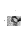
- 3 is a transmission electron micrograph of the exhaust gas purification catalyst of Example 1.
- FIG. It is a figure which shows the result of the energy dispersive X ray analysis in the area
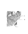
- FIG. 7 is a transmission electron micrograph of the exhaust gas purification catalyst of Comparative Example 1; It is a figure which shows the result of energy dispersive X ray analysis in the area
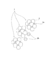
- FIG. 1 is a block diagram schematically showing an exhaust gas purification catalyst according to the first embodiment.
- the oxide 4a represented by the following general formula (1) is supported on the oxide 2 having the ability to absorb and release oxygen. is there.
- the particle diameter of the oxide 4a is typically 3 to 10 nm.
- the oxide 4 b represented by the general formula (1) shown for reference in FIG. 1 is not supported by the oxide 2 having an oxygen absorbing and releasing ability.
- the particle diameter of the oxide 4b is typically greater than 50 nm.
- La is at least one member selected from the group consisting of lanthanum
- M is barium (Ba), strontium (Sr) and calcium (Ca)
- M ′ is iron (Fe), cobalt (Co)
- ⁇ represents an oxygen deficiency
- x and ⁇ satisfy the relationship of 0 ⁇ x ⁇ 1, 0 ⁇ ⁇ ⁇ 1)
- the meaning of “the oxide represented by the general formula (1) is supported on the oxide having the ability to absorb and release oxygen” in the present invention is “the oxide B is supported on the oxide B.” This will be described in detail using the example of
- the oxide B in the aggregated state which can be distinguished from the oxide A when observed by a transmission electron microscope (TEM), does not correspond to that supported by the oxide A.
- TEM transmission electron microscope
- the oxide B in the aggregated state is an oxide B which can not be distinguished from the oxide A, and the oxide A is subjected to energy dispersive X-ray analysis
- the oxide B supported by the oxide A corresponds to the oxide A on which the constituent elements of the oxide B are detected together with the constituent elements of the oxide A when the elemental analysis is performed by EDX (measurement range: beam diameter 5 nm)
- EDX measurement range: beam diameter 5 nm
- the exhaust gas purification catalyst exhibits excellent purification performance even when no noble metal is used as an essential component.
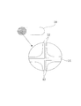
- FIG. 2 is a diagram for explaining the estimated reaction mechanism.
- the oxide 4a represented by the general formula (1) supported on the oxide 2 having the ability to absorb and release oxygen functions as an active point of the catalytic reaction.
- the oxide 2 having the ability to absorb and release oxygen which supports the oxide 4a promotes the catalytic reaction by absorbing and releasing oxygen necessary for the catalytic reaction. Thereby, the ability to absorb and release oxygen is improved, and the purification activity at low temperature is excellent.
- FIG. 3 is a schematic view of a conventional exhaust gas purification catalyst.
- the conventional exhaust gas purification catalyst 10 is in a state where the oxide 2 b represented by the following general formula (1) is not supported on the oxide 2 having the ability to absorb and release oxygen, and is aggregated.
- the oxide 2 b represented by the following general formula (1)
- the particle size of the agglomerate is typically 100 to 500 nm.
- the particle diameter of the oxide having the ability to absorb and release oxygen is preferably 1 to 50 nm, and more preferably 5 to 20 nm. If the particle size is less than 1 nm, there is a possibility that the oxide having the ability to absorb and release oxygen aggregates and the desired effect can not be obtained, and if the particle size is more than 50 nm, the general formula (1) There is a possibility that the desired effect can not be obtained because the oxide represented by is not supported.
- the particle diameter of the oxide represented by the general formula (1) supported by the oxide having the ability to absorb and release oxygen is 1 to 30 nm. And preferably 3 to 10 nm. If the particle size is less than 1 nm, there is a possibility that the oxide having the ability to absorb and release oxygen aggregates and the desired effect can not be obtained, and if the particle size is more than 30 nm, the general formula (1) There is a possibility that the desired effect can not be obtained without being supported by the oxide represented by In particular, when the particle diameter is 10 nm or less, it is preferable from the viewpoint of showing more excellent purification performance.
- the oxide represented by the general formula (1) is considered to function as the active site of the catalytic reaction, and from the viewpoint that the active site can be increased by using the same amount,
- the particle size of the oxide represented by the general formula (1) is preferably smaller than the particle size of the oxide having the ability to absorb and release oxygen.
- particle diameter refers to the contour line of the oxide particles (observation surface) observed using an observation means such as a scanning electron microscope (SEM) or a transmission electron microscope (TEM). Of the distances between any two points, it means the largest distance. However, the present invention is not limited to such a range, and it is needless to say that the range may be deviated as long as the effects of the present invention can be effectively exhibited.
- the oxide having an oxygen absorbing and releasing ability is preferably an oxide containing at least one of cerium (Ce) and zirconium (Zr), and cerium (Ce) More preferably, it is a composite oxide containing at least one of zirconium and zirconium (Zr).
- Oxides containing cerium (Ce) are excellent in terms of their ability to absorb and release oxygen, and oxides containing zirconium (Zr) have a high ability to release oxygen and have a high rate of oxygen absorption and release. Excellent from.
- a composite oxide containing cerium (Ce) and zirconium (Zr) is excellent in terms of both of a large amount of oxygen release and a high oxygen absorption and release rate.
- an oxide containing cerium and zirconium for example, a composite oxide containing zirconium, cerium, lanthanum and neodymium (Zr-Ce-La-Nd-Ox) or a composite oxide containing zirconium, cerium and neodymium Examples include (Zr-Ce-Nd-Ox), (Zr-La-Ox) containing zirconium and lanthanum, and the like, but are not limited thereto. That is, conventionally known materials can be applied as long as they have oxygen absorbing and releasing ability. For example, an oxide containing cerium and zirconium, in which part of cerium and zirconium is substituted by an alkali metal element, an alkaline earth metal element, a rare earth element or the like can be mentioned.
- the cerium in the composite oxide is a composite oxide containing cerium (Ce) and zirconium (Zr)
- the content is preferably 5% by mass or more in terms of cerium oxide (CeO 2 ) from the viewpoint that the CO conversion is improved, and it is preferably 20% by mass or more from the viewpoint that the CO conversion is further improved.
- the cerium content in the composite oxide is preferably 5% by mass to 90% by mass in terms of cerium oxide (CeO 2 ), and is preferably 20% by mass to 80% by mass More preferable. If the content of cerium in the composite oxide is more than 90% by mass in terms of cerium oxide (CeO 2 ), the effect of improving the CO conversion may be reduced.
- the oxide represented by the general formula (1) in the exhaust gas purification catalyst of the first embodiment is preferably a perovskite oxide.
- the perovskite-type oxide has the advantage of being excellent in durability because it has a crystal structure.
- the exhaust gas purification catalyst of the first embodiment can be manufactured, for example, by the following manufacturing method.
- an aggregate of fluorite-type oxide particles containing cerium and zirconium is prepared as an oxide capable of absorbing and releasing oxygen.
- a lanthanum salt of a carboxylic acid, a barium salt of a carboxylic acid, a strontium salt of a carboxylic acid, and a calcium salt of a carboxylic acid prepared so that the composition of the oxide represented by the general formula (1) is desired.
- the obtained oxide having the ability to absorb and release oxygen is immersed in the obtained solution.
- the atmosphere around the solution is reduced to a reduced pressure lower than atmospheric pressure using an aspirator or the like to degas the gas in the pores of the oxide having the ability to absorb and release oxygen, so that the solution is easily impregnated and supported.
- the oxide having the ability to absorb and release oxygen in which the lanthanum salt of carboxylic acid and the metal salt of carboxylic acid are impregnated and supported, is dried, pre-sintered at about 400 ° C., main-sintered at about 700 ° C.
- the exhaust gas purification catalyst of one embodiment can be obtained.
- a lanthanum salt of nitric acid and a metal salt of nitric acid are easily impregnated because they have almost no viscosity, but they easily move along with the evaporation of the solution during drying or baking and are difficult to be supported.
- a lanthanum salt of carboxylic acid or a metal salt of carboxylic acid are used, these form a metal complex salt and have viscosity, so by degassing the gas in the pore, It can be impregnated.
- these metal complex salts are viscous at the time of drying or baking, they are difficult to move as the solution evaporates, and are supported.
- carboxylic acid examples include those having 1 to 4 carboxyl groups.
- gluconic acid, malic acid, maleic acid, acetic acid, succinic acid, fumaric acid, propionic acid, methacrylic acid, acrylic acid, citric acid, tartaric acid, itaconic acid, formic acid, acetic acid, malonic acid and the like can be mentioned.
- FIG. 4 is a block diagram schematically showing an exhaust gas purification monolith catalyst according to a third embodiment.
- the catalyst layer 12 containing the exhaust gas purification catalyst according to the first embodiment described above corresponds to the exhaust flow passage 14 a of the monolithic carrier 14. It is formed.
- monolithic carriers include those made of ceramics such as cordierite and heat resistant materials such as metals such as ferritic stainless steel.
- the exhaust gas purification catalyst exhibits excellent purification performance even when no noble metal is used as an essential component.
- excellent purification performance can be exhibited even when the flow velocity of the exhaust gas is high.
- Example 1 Impregnation of a lactic acid solution containing lanthanum and a lactic acid solution containing iron into a Ce-Zr-based oxide (72% by mass ZrO 2 -21% by mass CeO 2 -5% by mass Nd 2 O 3 -2% by mass La 2 O 3 ) Then, the pressure was reduced for 1 hour, and thereafter, the catalyst was calcined in air at 400 ° C. for 2 hours and at 700 ° C. for 5 hours to obtain an exhaust gas purification catalyst of this example.
- the particle size was measured by observation with a scanning electron microscope (SEM). A part of the specifications of the exhaust gas purification catalyst of this example is shown in Table 1.
- FIG. 5 is a transmission electron microscope (TEM) photograph of the exhaust gas purification catalyst of this example.
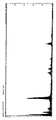
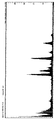
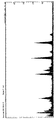
- FIG. 6 shows the results of energy dispersive X-ray analysis in the region A shown in FIG.
- FIG. 7 shows the results of energy dispersive X-ray analysis in the region B shown in FIG.
- FIG. 8 is a transmission electron micrograph in the region A shown in FIG.
- zirconium (Zr) and cerium (Ce) are mainly detected by elemental analysis by energy dispersive X-ray analysis (EDX) from particles of about 10 nm observed in the region A, and further, Lanthanum (La), neodymium (Nd) and iron (Fe) were detected.
- EDX energy dispersive X-ray analysis
- La Lanthanum
- Nd neodymium
- Fe iron
- iron (Fe) and lanthanum (La) were mainly detected from particles of about 50 nm or more observed in the region B.
- X-ray photoelectron spectroscopy separately measured from the period of the interference fringes in FIG. 8 that the Ce—Zr based oxide particles which are a fluorite type oxide and the LaFeO 3 particles which are a perovskite type oxide are present XPS) analysis revealed. The same measurement results were obtained in each of the examples.
- Example 2 Impregnated with a lactic acid solution containing lactic acid solution and nickel containing lanthanum Ce-Zr-based oxide (72 wt% ZrO 2 -21 wt% CeO 2 -5 wt% Nd 2 O 3 -2 wt% La 2 O 3) Then, the pressure was reduced for 1 hour, and thereafter, the catalyst was calcined in air at 400 ° C. for 2 hours and at 700 ° C. for 5 hours to obtain an exhaust gas purification catalyst of this example.
- the particle size was measured by observation with a scanning electron microscope (SEM). A part of the specifications of the exhaust gas purification catalyst of this example is shown in Table 1.
- Example 3 Impregnation of a lactic acid solution containing lanthanum and a lactic acid solution containing manganese into a Ce-Zr-based oxide (72 mass% ZrO 2 -21 mass% CeO 2 -5 mass% Nd 2 O 3 -2 mass% La 2 O 3 ) Then, the pressure was reduced for 1 hour, and thereafter, the catalyst was calcined in air at 400 ° C. for 2 hours and at 700 ° C. for 5 hours to obtain an exhaust gas purification catalyst of this example.
- the particle size was measured by observation with a scanning electron microscope (SEM). A part of the specifications of the exhaust gas purification catalyst of this example is shown in Table 1.
- FIG. 9 is a transmission electron microscope (TEM) photograph of the exhaust gas purification catalyst of this example.
- FIG. 10 shows the results of energy dispersive X-ray analysis in the region A shown in FIG.
- FIG. 11 shows the results of energy dispersive X-ray analysis in the region B shown in FIG.
- iron (Fe) and lanthanum (La) were mainly detected by elemental analysis by energy dispersive X-ray analysis (EDX).
- EDX energy dispersive X-ray analysis
- zirconium (Zr) and cerium (Ce) were mainly detected from the matrix observed in the region B.
- CO conversion (%) (CO in- CO out ) / CO in x 100 (II) (In the formula (II), CO in is the CO concentration of the exhaust gas analyzer with respect to the gas when the sample does not pass, CO out is the CO concentration of the exhaust gas analyzer with respect to the gas after the sample passes Indicate
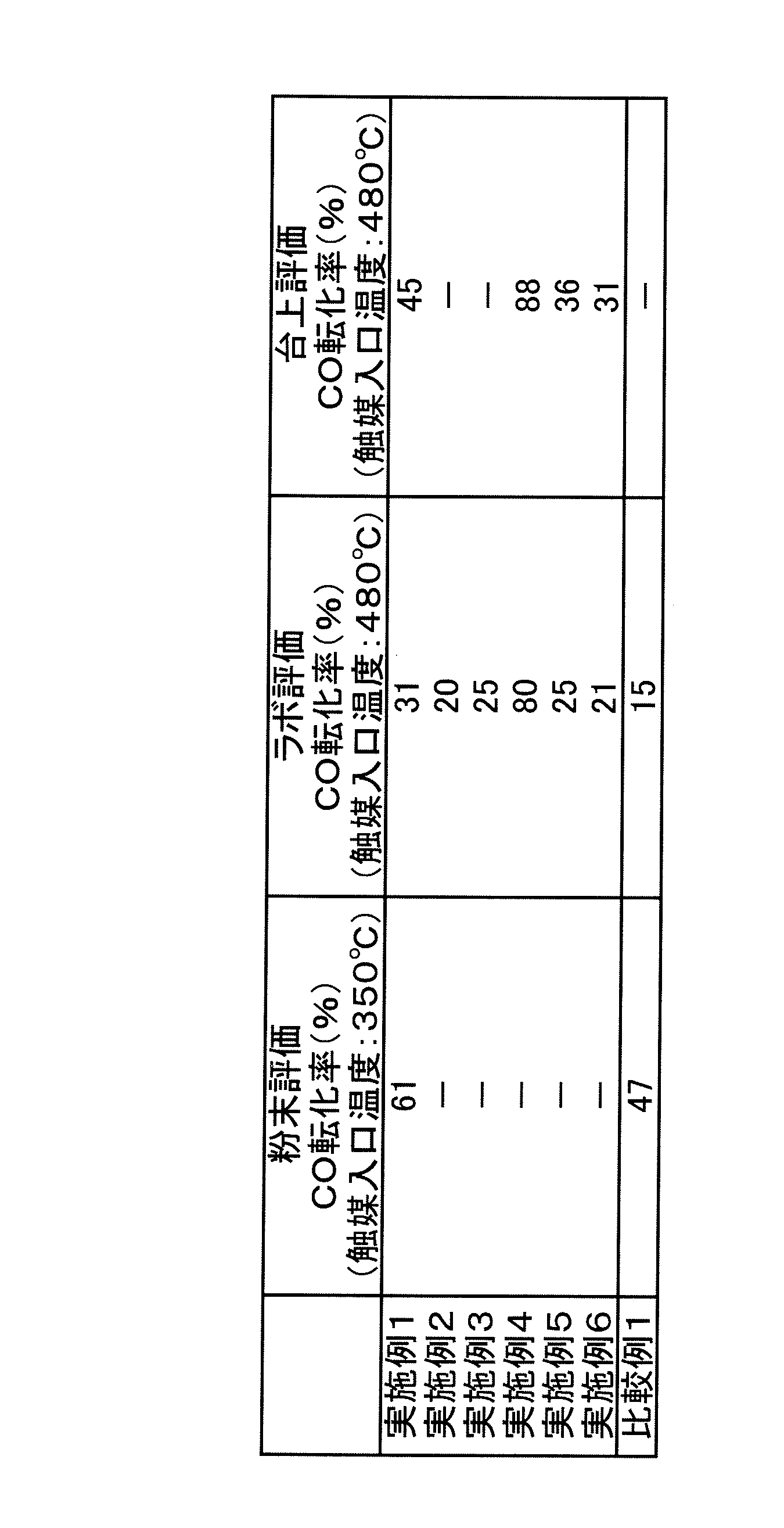
- Examples 1 to 6 belonging to the scope of the present invention have a high conversion rate of carbon monoxide and excellent oxidation performance as compared with Comparative Example 1 outside the present invention. . At the present time, it is considered that Example 1 and Example 4 are particularly excellent.
- Example 4 a catalyst slurry of each example obtained using ceria-zirconia composite oxide in which the amount of ceria was changed instead of the Ce-Zr-based oxide, boehmite alumina, nitric acid and ion exchanged water was prepared. This was used to obtain an exhaust gas purification monolith catalyst of each example.
- the CO concentration of the exhaust gas purification monolith catalyst of each example was measured using an exhaust gas analyzer (MEXA-9100 manufactured by Horiba, Ltd.) under the following conditions. The CO conversion was calculated from the above formula (II). The obtained result is shown in FIG.
- the amount of ceria (CeO 2 ) in the ceria-zirconia composite oxide is preferably 5% by mass or more, and more preferably 20% by mass or more. In particular, it is understood that 5 to 90% by mass is preferable, and 20 to 80% by mass is preferable.
Landscapes
- Chemical & Material Sciences (AREA)
- Engineering & Computer Science (AREA)
- Chemical Kinetics & Catalysis (AREA)
- Materials Engineering (AREA)
- Organic Chemistry (AREA)
- Combustion & Propulsion (AREA)
- Health & Medical Sciences (AREA)
- Ceramic Engineering (AREA)
- Toxicology (AREA)
- Mechanical Engineering (AREA)
- General Engineering & Computer Science (AREA)
- Biomedical Technology (AREA)
- Environmental & Geological Engineering (AREA)
- Analytical Chemistry (AREA)
- General Chemical & Material Sciences (AREA)
- Oil, Petroleum & Natural Gas (AREA)
- Catalysts (AREA)
- Crystallography & Structural Chemistry (AREA)
Abstract
Description
また、低温下で、優れた酸素吸放出性を有し、かつ、この酸素吸放出機能の持続性に優れるPM酸化触媒や排気ガス浄化触媒として、ペロブスカイト型構造を有する複合酸化物であって低温での酸素吸放出性に優れる酸素低温吸放出材と、ペロブスカイト型構造を有する複合酸化物であって酸素移動性に優れる酸素易移動材とを含有するものが提案されている(特許文献2参照。)。
(式(1)中、Laはランタン、Mはバリウム(Ba)、ストロンチウム(Sr)及びカルシウム(Ca)からなる群より選ばれる少なくとも1種、M’は鉄(Fe)、コバルト(Co)、ニッケル(Ni)及びマンガン(Mn)からなる群より選ばれる少なくとも1種、δは酸素欠損量を示し、x及びδは、0<x≦1、0≦δ≦1の関係を満足する。)
(式(1)中、Laはランタン、Mはバリウム(Ba)、ストロンチウム(Sr)及びカルシウム(Ca)からなる群より選ばれる少なくとも1種、M’は鉄(Fe)、コバルト(Co)、ニッケル(Ni)及びマンガン(Mn)からなる群より選ばれる少なくとも1種、δは酸素欠損量を示し、x及びδは、0<x≦1、0≦δ≦1の関係を満足する。)
(式(1)中、Laはランタン、Mはバリウム(Ba)、ストロンチウム(Sr)及びカルシウム(Ca)からなる群より選ばれる少なくとも1種、M’は鉄(Fe)、コバルト(Co)、ニッケル(Ni)及びマンガン(Mn)からなる群より選ばれる少なくとも1種、δは酸素欠損量を示し、x及びδは、0<x≦1、0≦δ≦1の関係を満足する。)
まず、本発明の一実施形態に係る排気ガス浄化触媒について図面を参照しながら詳細に説明する。図1は、第1の実施形態に係る排気ガス浄化触媒を模式的に示す構成図である。同図に示すように、第1の実施形態の排気ガス浄化触媒1は、酸素吸放出能を有する酸化物2に下記一般式(1)で表される酸化物4aが担持されているものである。また、酸化物4aの粒子径は代表的には3~10nmであ。なお、図1中に参考のために示した一般式(1)で表される酸化物4bは、酸素吸放出能を有する酸化物2に担持されているものではない。また、酸化物4bの粒子径は代表的には50nm超である。
(式(1)中、Laはランタン、Mはバリウム(Ba)、ストロンチウム(Sr)及びカルシウム(Ca)からなる群より選ばれる少なくとも1種、M’は鉄(Fe)、コバルト(Co)、ニッケル(Ni)及びマンガン(Mn)からなる群より選ばれる少なくとも1種、δは酸素欠損量を示し、x及びδは、0<x≦1、0≦δ≦1の関係を満足する。)
次に、本発明の一実施形態に係る排気ガス浄化触媒の製造方法について、上述した本発明の一実施形態に係る排気ガス浄化触媒を挙げて詳細に説明する。但し、本発明の排気ガス浄化触媒は、このような製造方法により作製されたものに限定されるものではない。
次に、本発明の一実施形態に係る排気ガス浄化モノリス触媒について図面を参照しながら詳細に説明する。図4は、第3の実施形態に係る排気ガス浄化モノリス触媒を模式的に示す構成図である。同図に示すように、第3の実施形態の排気ガス浄化モノリス触媒10は、上述した第1の実施形態の排気ガス浄化触媒を含有する触媒層12が、モノリス担体14の排気流路14aに形成されているものである。なお、モノリス担体としては、コーディエライトなどのセラミックスやフェライト系ステンレスなどの金属等の耐熱性材料から成るものなどを挙げることができる。
ランタンを含む乳酸溶液と鉄を含む乳酸溶液をCe-Zr系酸化物(72質量%ZrO2-21質量%CeO2-5質量%Nd2O3-2質量%La2O3)に含浸し、次いで、1時間減圧させ、しかる後、400℃で2時間、700℃で5時間、空気中で焼成して、本例の排気ガス浄化触媒を得た。なお、LaFeO3とCe-Zr系酸化物の質量比は、LaFeO3:Ce-Zr系酸化物=30:70である。また、粒子径は、走査型電子顕微鏡(SEM)による観察によって測定した。本例の排気ガス浄化触媒の仕様の一部を表1に示す。
ランタンを含む乳酸溶液とニッケルを含む乳酸溶液をCe-Zr系酸化物(72質量%ZrO2-21質量%CeO2-5質量%Nd2O3-2質量%La2O3)に含浸し、次いで、1時間減圧させ、しかる後、400℃で2時間、700℃で5時間、空気中で焼成して、本例の排気ガス浄化触媒を得た。なお、LaNiO3とCe-Zr系酸化物の質量比は、LaNiO3:Ce-Zr系酸化物=30:70である。また、粒子径は、走査型電子顕微鏡(SEM)による観察によって測定した。本例の排気ガス浄化触媒の仕様の一部を表1に示す。
ランタンを含む乳酸溶液とマンガンを含む乳酸溶液をCe-Zr系酸化物(72質量%ZrO2-21質量%CeO2-5質量%Nd2O3-2質量%La2O3)に含浸し、次いで、1時間減圧させ、しかる後、400℃で2時間、700℃で5時間、空気中で焼成して、本例の排気ガス浄化触媒を得た。なお、LaMnO3とCe-Zr系酸化物の質量比は、LaMnO3:Ce-Zr系酸化物=30:70である。また、粒子径は、走査型電子顕微鏡(SEM)による観察によって測定した。本例の排気ガス浄化触媒の仕様の一部を表1に示す。
ランタンを含む乳酸溶液とストロンチウムを含む乳酸溶液と鉄を含む乳酸溶液をCe-Zr系酸化物(70質量%ZrO2-20質量%CeO2-10質量%Nd2O3)に含浸し、次いで、1時間減圧させ、しかる後、400℃で2時間、700℃で5時間、空気中で焼成して、本例の排気ガス浄化触媒を得た。なお、La0.8Sr0.2FeO3とCe-Zr系酸化物の質量比は、La0.8Sr0.2FeO3:Ce-Zr系酸化物=30:70である。また、粒子径は、走査型電子顕微鏡(SEM)による観察によって測定した。本例の排気ガス浄化触媒の仕様の一部を表1に示す。
ランタンを含む乳酸溶液と鉄を含む乳酸溶液とマンガンを含む乳酸溶液をCe-Zr系酸化物(70質量%ZrO2-20質量%CeO2-10質量%Nd2O3)に含浸し、次いで、1時間減圧させ、しかる後、400℃で2時間、700℃で5時間、空気中で焼成して、本例の排気ガス浄化触媒を得た。なお、LaFe0.8Mn0.2O3とCe-Zr系酸化物の質量比は、LaFe0.8Mn0.2O3:Ce-Zr系酸化物=30:70である。また、粒子径は、走査型電子顕微鏡(SEM)による観察によって測定した。本例の排気ガス浄化触媒の仕様の一部を表1に示す。
ランタンを含む乳酸溶液と鉄を含む乳酸溶液とニッケルを含む乳酸溶液をCe-Zr系酸化物(70質量%ZrO2-20質量%CeO2-10質量%Nd2O3)に含浸し、次いで、1時間減圧させ、しかる後、400℃で2時間、700℃で5時間、空気中で焼成して、本例の排気ガス浄化触媒を得た。なお、LaFe0.8Ni0.2O3とCe-Zr系酸化物の質量比は、LaFe0.8Ni0.2O3:Ce-Zr系酸化物=30:70である。また、粒子径は、走査型電子顕微鏡(SEM)による観察によって測定した。本例の排気ガス浄化触媒の仕様の一部を表1に示す。
ランタンを含む硝酸溶液と鉄を含む硝酸溶液をCe-Zr系酸化物(72質量%ZrO2-21質量%CeO2-5質量%Nd2O3-2質量%La2O3)に含浸し、次いで、150℃で一晩乾燥させ、更に乳鉢で粉砕し、しかる後、400℃で2時間、700℃で5時間、空気中で焼成して、本例の酸化物を得た。なお、LaFeO3とCe-Zr系酸化物の質量比は、LaFeO3:Ce-Zr系酸化物=30:70である。また、粒子径は、走査型電子顕微鏡(SEM)による観察によって測定した。LaFeO3粒子の凝集体の粒子径は、100~500nmであった。本例の排気ガス浄化触媒の仕様の一部を表1に示す。

各例の排気ガス浄化触媒を用いて浄化性能を評価した。得られた結果を表2に示す。
各例の排気ガス浄化触媒に対して、下記条件下、四重極質量分析装置を用いてCO2を測定した。CO転化率は下記式(I)より算出した。
・触媒量:0.2g(粉末)
・流量 :50cm3/min
・ガス組成:CO;0.4体積%、O2;0.2体積%、He;バランス
(予め、COが100%反応したときの質量数44の質量分析計の値をCO2生成率100%とし、また、COが0%反応したときの質量数44の質量分析計の値をCO2生成率0%とし、検量線を作成する。これをY=Ax+Bとし、xは質量分析計の質量数44の値とする。xは触媒出口のCO2であり、式(1)で(CO2out)と表記する。)
各例の排気ガス浄化触媒とベーマイトアルミナ、硝酸及びイオン交換水とを用いて得られた各例の触媒スラリーを作製し、これを用いて各例の排気ガス浄化モノリス触媒を得た。各例の排気ガス浄化モノリス触媒に対して、下記条件下、排気ガス分析装置(堀場製作所製、MEXA-7100D)を用いてCO濃度を測定した。CO転化率は下記式(II)より算出した。
・触媒容量:119cm3
・ガス流量:40L/min
・ガス組成(ストイキ):O2;0.6体積%、CO;0.6体積%、NO;1000体積ppm、HC;1665体積ppmC、H2;0.2体積%、H2O;10体積%、CO2;13.9体積%
(式(II)中、COinは、サンプルを通さない場合のガスに対しての排気ガス分析装置のCO濃度、COoutは、サンプル通過後のガスに対しての排気ガス分析装置のCO濃度を示す。)
各例の排気ガス浄化触媒とベーマイトアルミナ、硝酸及びイオン交換水とを用いて得られた各例の触媒スラリーを作製し、これを用いて各例の排気ガス浄化モノリス触媒を得た。各例の排気ガス浄化モノリス触媒に対して、下記条件下、排気ガス分析装置(堀場製作所製、MEXA-7500D)を用いてCO濃度を測定した。CO転化率は上記式(II)より算出した。
・日産自動車製エンジン使用
・触媒容量:119cm3
・ガス流量:60m3/h
・ガス組成(ストイキ):HC;約2000体積ppmC、CO;約0.54体積%、NO;約1500体積ppm、O2;約0.56体積%、CO2;14.6体積%
実施例4において、Ce-Zr系酸化物に替えてセリア量をそれぞれ変更したセリアジルコニア複合酸化物と、ベーマイトアルミナ、硝酸及びイオン交換水とを用いて得られた各例の触媒スラリーを作製し、これを用いて各例の排気ガス浄化モノリス触媒を得た。各例の排気ガス浄化モノリス触媒に対して、下記条件下、排気ガス分析装置(堀場製作所製、MEXA-9100)を用いてCO濃度を測定した。CO転化率は上記式(II)より算出した。得られた結果を図12に示す。
・日産自動車製エンジン使用
・触媒コート量:268g/L+DPR:32g/L
・ガス流量:60m3/h
・A/F振幅:±0.2、1.0Hz
・ガス組成(ストイキ):HC;約2000体積ppmC、CO;約0.54体積%、NO;約1500体積ppm、O2;約0.56体積%、CO2;14.6体積%
2 酸素吸放出能を有する酸化物
4a、4b 一般式(1)で表される酸化物
10 排気ガス浄化モノリス触媒
12 触媒層
14 モノリス担体
Claims (9)
- 酸素吸放出能を有する酸化物に、一般式(1)
LaxM1-xM’O3-δ・・・(1)
(式(1)中、Laはランタン、Mはバリウム(Ba)、ストロンチウム(Sr)及びカルシウム(Ca)からなる群より選ばれる少なくとも1種、M’は鉄(Fe)、コバルト(Co)、ニッケル(Ni)及びマンガン(Mn)からなる群より選ばれる少なくとも1種、δは酸素欠損量を示し、x及びδは、0<x≦1、0≦δ≦1の関係を満足する。)で表される酸化物が担持されていることを特徴とする排気ガス浄化触媒。 - 上記酸素吸放出能を有する酸化物の粒子径が、1~50nmであり、
上記一般式(1)で表される酸化物の粒子径が、1~30nmである
ことを特徴とする請求項1に記載の排気ガス浄化触媒。 - 上記酸素吸放出能を有する酸化物の粒子径が、5~20nmであり、
上記一般式(1)で表される酸化物の粒子径が、3~10nmである
ことを特徴とする請求項1又は2に記載の排気ガス浄化触媒。 - 上記酸素吸放出能を有する酸化物が、セリウム及びジルコニウムの少なくとも1種を含む酸化物であることを特徴とする請求項1~3のいずれか1つの項に記載の排気ガス浄化触媒。
- 上記酸素吸放出能を有する酸化物が、セリウムとジルコニウムとを含む複合酸化物であることを特徴とする請求項1~4のいずれか1つの項に記載の排気ガス浄化触媒。
- 上記複合酸化物中のセリウム含有量がセリウム酸化物(CeO2)換算で5質量%以上であることを特徴とする請求項5に記載の排気ガス浄化触媒。
- 上記複合酸化物中のセリウム含有量がセリウム酸化物(CeO2)換算で20質量%以上であることを特徴とする請求項5又は6に記載の排気ガス浄化触媒。
- 請求項1~7のいずれか1つの項に記載の排気ガス浄化触媒を含有する触媒層が、モノリス担体の排気流路に形成されていることを特徴とする排気ガス浄化モノリス触媒。
- 請求項1~7のいずれか1つの項に記載の排気ガス浄化触媒を製造するに当たり、
カルボン酸のランタン塩と、カルボン酸のバリウム塩、カルボン酸のストロンチウム塩、カルボン酸のカルシウム塩、カルボン酸の鉄塩、カルボン酸のコバルト塩、カルボン酸のニッケル塩及びカルボン酸のマンガン塩からなる群より選ばれる少なくとも1種のカルボン酸の金属塩とを含む溶液に、酸素吸放出能を有する酸化物を浸漬し、溶液周囲の雰囲気を大気圧より低い減圧状態として、酸素吸放出能を有する酸化物にカルボン酸のランタン塩とカルボン酸の金属塩とを含浸担持させる、ことを特徴とする排気ガス浄化触媒の製造方法。
Priority Applications (4)
| Application Number | Priority Date | Filing Date | Title |
|---|---|---|---|
| JP2013507669A JP5720772B2 (ja) | 2011-03-31 | 2012-03-28 | 排気ガス浄化触媒、排気ガス浄化モノリス触媒及び排気ガス浄化触媒の製造方法 |
| US14/006,841 US9101914B2 (en) | 2011-03-31 | 2012-03-28 | Exhaust gas purifying catalyst, exhaust gas purifying monolith catalyst, and method for manufacturing exhaust gas purifying catalyst |
| CN201280010755.9A CN103402630B (zh) | 2011-03-31 | 2012-03-28 | 废气净化催化剂、废气净化整体式催化剂以及废气净化催化剂的制造方法 |
| EP12763126.5A EP2692432B1 (en) | 2011-03-31 | 2012-03-28 | Exhaust gas purification catalyst, exhaust gas purification monolith catalyst, and process for producing exhaust gas purification catalyst |
Applications Claiming Priority (2)
| Application Number | Priority Date | Filing Date | Title |
|---|---|---|---|
| JP2011077444 | 2011-03-31 | ||
| JP2011-077444 | 2011-03-31 |
Publications (1)
| Publication Number | Publication Date |
|---|---|
| WO2012133526A1 true WO2012133526A1 (ja) | 2012-10-04 |
Family
ID=46931235
Family Applications (1)
| Application Number | Title | Priority Date | Filing Date |
|---|---|---|---|
| PCT/JP2012/058122 Ceased WO2012133526A1 (ja) | 2011-03-31 | 2012-03-28 | 排気ガス浄化触媒、排気ガス浄化モノリス触媒及び排気ガス浄化触媒の製造方法 |
Country Status (5)
| Country | Link |
|---|---|
| US (1) | US9101914B2 (ja) |
| EP (1) | EP2692432B1 (ja) |
| JP (1) | JP5720772B2 (ja) |
| CN (1) | CN103402630B (ja) |
| WO (1) | WO2012133526A1 (ja) |
Cited By (8)
| Publication number | Priority date | Publication date | Assignee | Title |
|---|---|---|---|---|
| WO2014038294A1 (ja) * | 2012-09-10 | 2014-03-13 | 日産自動車株式会社 | 排気ガス浄化触媒、排気ガス浄化モノリス触媒及び排気ガス浄化触媒の製造方法 |
| EP2878359A1 (en) * | 2013-11-29 | 2015-06-03 | Umicore Ag & Co. Kg | Use of mixed oxides as oxygen storage components |
| WO2015125206A1 (ja) * | 2014-02-18 | 2015-08-27 | 日産自動車株式会社 | 排気ガス浄化触媒及びその製造方法 |
| WO2015173880A1 (ja) * | 2014-05-13 | 2015-11-19 | 日産自動車株式会社 | 水素生成用触媒及び排ガス浄化用触媒 |
| JP2016019955A (ja) * | 2014-07-15 | 2016-02-04 | 株式会社キャタラー | 排ガス浄化用触媒 |
| US10052615B2 (en) | 2013-11-29 | 2018-08-21 | Umicore Ag & Co. Kg | Oxygen storage materials |
| CN109647420A (zh) * | 2018-12-27 | 2019-04-19 | 中国科学院广州地球化学研究所 | 用于热催化氧化甲苯的钙掺杂钴酸镧钙钛矿型氧化物及其制备方法和应用 |
| JP2022518137A (ja) * | 2019-09-04 | 2022-03-14 | 有研稀土高技術有限公司 | 希土類マンガン/セリウム-ジルコニウムベースの複合化合物、その調製方法および用途 |
Families Citing this family (7)
| Publication number | Priority date | Publication date | Assignee | Title |
|---|---|---|---|---|
| DE102011107702A1 (de) | 2011-07-14 | 2013-01-17 | Sasol Germany Gmbh | Verfahren zur Herstellung von Kompositen aus Aluminiumoxid und Cer-/Zirkonium-Mischoxiden |
| JP6362040B2 (ja) * | 2014-05-13 | 2018-07-25 | 日産自動車株式会社 | 排ガス浄化用触媒 |
| US9662639B2 (en) * | 2015-05-11 | 2017-05-30 | University Of Wyoming | Catalytic effects of oxygen carrier based chemical-looping reforming of CH4 with CO2 |
| KR102434321B1 (ko) | 2016-11-14 | 2022-08-18 | 리써치 트라이앵글 인스티튜트 | 페로브스카이트 촉매 및 이의 용도 |
| EP4041450A1 (en) * | 2020-08-12 | 2022-08-17 | Neo Performance Materials (Singapore), PTE. LTD. | Oxygen storage capacity enhanced compositions |
| WO2023148473A1 (en) * | 2022-02-03 | 2023-08-10 | Johnson Matthey Public Limited Company | Surface-modified ceria-zirconia mixed oxide compound for gasoline exhaust gas applications |
| CN114917916A (zh) * | 2022-05-30 | 2022-08-19 | 昆明理工大学 | 一种高储氧量和高稳定性载氧体及其制备方法 |
Citations (5)
| Publication number | Priority date | Publication date | Assignee | Title |
|---|---|---|---|---|
| JPH0531367A (ja) * | 1991-07-29 | 1993-02-09 | Daihatsu Motor Co Ltd | 排気ガス浄化用触媒 |
| JPH07136518A (ja) * | 1993-11-22 | 1995-05-30 | Nissan Motor Co Ltd | 排気ガス浄化用触媒 |
| JP2004181435A (ja) * | 2002-10-11 | 2004-07-02 | Daihatsu Motor Co Ltd | 耐熱性複合酸化物、排ガス浄化用触媒およびその製造方法 |
| JP2005306618A (ja) | 2004-04-16 | 2005-11-04 | Dowa Mining Co Ltd | ペロブスカイト型複合酸化物およびその製造方法ならびにこれを用いた触媒 |
| JP2009131774A (ja) | 2007-11-30 | 2009-06-18 | Nissan Motor Co Ltd | Pm酸化触媒及びこれを用いた排気ガス浄化触媒 |
Family Cites Families (16)
| Publication number | Priority date | Publication date | Assignee | Title |
|---|---|---|---|---|
| JPH0722705B2 (ja) * | 1986-03-20 | 1995-03-15 | 松下電器産業株式会社 | 酸化触媒の製造方法 |
| US5243103A (en) | 1988-05-24 | 1993-09-07 | Solvay S.A. | Process for obtaining catalytic compositions and process for hydrogenation of chlorofluoroalkenes by means of these compositions |
| FR2631858A1 (fr) | 1988-05-24 | 1989-12-01 | Solvay | Compositions catalytiques, procede pour leur obtention et procede d'hydrogenation de chlorofluoralcenes au moyen de ces compositions |
| EP0525677B1 (en) * | 1991-07-29 | 1995-12-13 | Daihatsu Motor Company, Ltd. | Exhaust gas purifying catalyst and method of preparing the same |
| JP2001276626A (ja) * | 2000-04-03 | 2001-10-09 | Idemitsu Kosan Co Ltd | 水素化処理触媒とその製造方法、及び炭化水素油の水素化処理方法 |
| DK1145763T3 (da) | 1999-10-27 | 2012-10-08 | Idemitsu Kosan Co | Hydrogeneringskatalysator til carbonhydridolie, bærestof for denne samt fremgangsmåde til hydrogenering af carbonhydridolie |
| JP2002049963A (ja) * | 2000-08-04 | 2002-02-15 | Kubota Corp | 自動販売機の商品払出装置 |
| WO2002049963A1 (fr) | 2000-12-19 | 2002-06-27 | Idemitsu Kosan Co., Ltd. | Compose de titane, solution aqueuse contenant du titane, et procede de production de cette derniere |
| JP2006258911A (ja) | 2005-03-15 | 2006-09-28 | Denon Ltd | 再生装置及び再生方法 |
| JP2006256911A (ja) * | 2005-03-17 | 2006-09-28 | Tosoh Corp | セリア・ジルコニア系酸化物の製造方法 |
| JP4928931B2 (ja) * | 2006-12-20 | 2012-05-09 | 日本電工株式会社 | セリア−ジルコニア系複合酸化物及びその製造方法 |
| JP4985299B2 (ja) * | 2007-10-10 | 2012-07-25 | マツダ株式会社 | 排ガス成分浄化用触媒材及び同触媒材付パティキュレートフィルタ |
| EP2055365B1 (en) | 2007-10-10 | 2018-02-28 | Mazda Motor Corporation | Catalyst-supported particulate filter |
| FR2942624B1 (fr) * | 2009-03-02 | 2011-03-18 | Rhodia Operations | Composition comprenant une perovskite a base de lanthane sur un support en alumine ou en oxyhydroxyde d'aluminium, procede de preparation et utilisation en catalyse |
| US8409518B2 (en) * | 2009-03-16 | 2013-04-02 | GM Global Technology Operations LLC | Sulfur tolerant perovskite supported catalysts |
| US8950174B2 (en) * | 2010-09-02 | 2015-02-10 | Basf Se | Catalysts for gasoline lean burn engines with improved NH3-formation activity |
-
2012
- 2012-03-28 US US14/006,841 patent/US9101914B2/en active Active
- 2012-03-28 CN CN201280010755.9A patent/CN103402630B/zh active Active
- 2012-03-28 WO PCT/JP2012/058122 patent/WO2012133526A1/ja not_active Ceased
- 2012-03-28 EP EP12763126.5A patent/EP2692432B1/en active Active
- 2012-03-28 JP JP2013507669A patent/JP5720772B2/ja active Active
Patent Citations (5)
| Publication number | Priority date | Publication date | Assignee | Title |
|---|---|---|---|---|
| JPH0531367A (ja) * | 1991-07-29 | 1993-02-09 | Daihatsu Motor Co Ltd | 排気ガス浄化用触媒 |
| JPH07136518A (ja) * | 1993-11-22 | 1995-05-30 | Nissan Motor Co Ltd | 排気ガス浄化用触媒 |
| JP2004181435A (ja) * | 2002-10-11 | 2004-07-02 | Daihatsu Motor Co Ltd | 耐熱性複合酸化物、排ガス浄化用触媒およびその製造方法 |
| JP2005306618A (ja) | 2004-04-16 | 2005-11-04 | Dowa Mining Co Ltd | ペロブスカイト型複合酸化物およびその製造方法ならびにこれを用いた触媒 |
| JP2009131774A (ja) | 2007-11-30 | 2009-06-18 | Nissan Motor Co Ltd | Pm酸化触媒及びこれを用いた排気ガス浄化触媒 |
Non-Patent Citations (1)
| Title |
|---|
| See also references of EP2692432A4 |
Cited By (14)
| Publication number | Priority date | Publication date | Assignee | Title |
|---|---|---|---|---|
| US9352301B2 (en) | 2012-09-10 | 2016-05-31 | Nissan Motor Co., Ltd. | Exhaust gas purification catalyst, exhaust gas purification monolith catalyst, and method for producing exhaust gas purification catalyst |
| WO2014038294A1 (ja) * | 2012-09-10 | 2014-03-13 | 日産自動車株式会社 | 排気ガス浄化触媒、排気ガス浄化モノリス触媒及び排気ガス浄化触媒の製造方法 |
| US10058851B2 (en) | 2013-11-29 | 2018-08-28 | Umicore Ag & Co. Kg | Use of mixed oxides as oxygen storage components |
| WO2015078875A1 (en) * | 2013-11-29 | 2015-06-04 | Umicore Ag & Co. Kg | Use of mixed oxides as oxygen storage components |
| US10052615B2 (en) | 2013-11-29 | 2018-08-21 | Umicore Ag & Co. Kg | Oxygen storage materials |
| EP2878359A1 (en) * | 2013-11-29 | 2015-06-03 | Umicore Ag & Co. Kg | Use of mixed oxides as oxygen storage components |
| WO2015125206A1 (ja) * | 2014-02-18 | 2015-08-27 | 日産自動車株式会社 | 排気ガス浄化触媒及びその製造方法 |
| JPWO2015125206A1 (ja) * | 2014-02-18 | 2017-03-30 | 日産自動車株式会社 | 排気ガス浄化触媒及びその製造方法 |
| US10245579B2 (en) | 2014-02-18 | 2019-04-02 | Nissan Motor Co., Ltd. | Exhaust gas purification catalyst and production method thereof |
| WO2015173880A1 (ja) * | 2014-05-13 | 2015-11-19 | 日産自動車株式会社 | 水素生成用触媒及び排ガス浄化用触媒 |
| JP2016019955A (ja) * | 2014-07-15 | 2016-02-04 | 株式会社キャタラー | 排ガス浄化用触媒 |
| CN109647420A (zh) * | 2018-12-27 | 2019-04-19 | 中国科学院广州地球化学研究所 | 用于热催化氧化甲苯的钙掺杂钴酸镧钙钛矿型氧化物及其制备方法和应用 |
| JP2022518137A (ja) * | 2019-09-04 | 2022-03-14 | 有研稀土高技術有限公司 | 希土類マンガン/セリウム-ジルコニウムベースの複合化合物、その調製方法および用途 |
| JP7346578B2 (ja) | 2019-09-04 | 2023-09-19 | 有研稀土高技術有限公司 | 希土類マンガン/セリウム-ジルコニウムベースの複合化合物、その調製方法および用途 |
Also Published As
| Publication number | Publication date |
|---|---|
| JP5720772B2 (ja) | 2015-05-20 |
| JPWO2012133526A1 (ja) | 2014-07-28 |
| CN103402630B (zh) | 2015-11-25 |
| CN103402630A (zh) | 2013-11-20 |
| US20140018235A1 (en) | 2014-01-16 |
| EP2692432B1 (en) | 2019-11-13 |
| EP2692432A4 (en) | 2014-10-29 |
| US9101914B2 (en) | 2015-08-11 |
| EP2692432A1 (en) | 2014-02-05 |
Similar Documents
| Publication | Publication Date | Title |
|---|---|---|
| JP5720772B2 (ja) | 排気ガス浄化触媒、排気ガス浄化モノリス触媒及び排気ガス浄化触媒の製造方法 | |
| JP5885004B2 (ja) | 排気ガス浄化触媒、排気ガス浄化モノリス触媒及び排気ガス浄化触媒の製造方法 | |
| JP6676394B2 (ja) | コアシェル担体及びその製造方法、そのコアシェル担体を用いた排ガス浄化用触媒及びその製造方法、並びに、その排ガス浄化用触媒を用いた排ガス浄化方法 | |
| JP7026530B2 (ja) | 排ガス浄化用三元触媒 | |
| JP2010099638A (ja) | 触媒、排ガス浄化用触媒及び触媒の製造方法 | |
| JP6256769B2 (ja) | 排気ガス浄化用触媒 | |
| JP5332539B2 (ja) | 浄化触媒 | |
| JP2010260046A (ja) | 排ガス浄化用触媒 | |
| US9993805B2 (en) | Catalyst composition for purifying exhaust gas and exhaust gas purifying catalyst | |
| US11484864B2 (en) | Exhaust gas-purifying three-way catalyst and method for producing same, and integral structure type exhaust gas-purifying catalyst | |
| WO2018088201A1 (ja) | 排ガス浄化用三元触媒及びその製造方法、並びに排ガス浄化用触媒コンバータ | |
| JP6036276B2 (ja) | 排気浄化触媒及び排気浄化触媒の製造方法 | |
| JP5299603B2 (ja) | 酸化物複合体前駆体水溶液、酸化物複合体の製造方法、酸化物複合体、その酸化物複合体を備える排ガス浄化用触媒及びその排ガス浄化用触媒を用いた排ガス浄化方法 | |
| JP6181260B1 (ja) | 排ガス浄化用の触媒組成物及び排ガス浄化触媒 | |
| Liotta et al. | Structural and morphological investigation of Ce0. 6Zr0. 4O2 oxides synthesized by sol-gel method: Influence of calcination and redox treatments | |
| JP2020070219A (ja) | セリア・ジルコニア系複合酸化物酸素吸収放出材料および排ガス浄化触媒 | |
| JP5589320B2 (ja) | 排気ガス浄化用触媒及びその製造方法 | |
| JP2018030100A (ja) | 排気ガス浄化用触媒、及びその製造方法、並びに排気ガス浄化用触媒コンバータ | |
| JP2007203160A (ja) | 排ガス浄化用触媒担体、それを用いた排ガス浄化用触媒及び排ガス浄化方法 | |
| US20260131284A1 (en) | Three-way catalyst and method for manufacturing the same | |
| JP5892712B2 (ja) | 排ガス浄化用触媒 | |
| JP5327526B2 (ja) | 酸化触媒及びその製造方法 | |
| JP5104352B2 (ja) | 排ガス浄化用触媒 | |
| JP4930898B2 (ja) | 排ガス浄化用触媒の製造方法及び排ガス浄化用触媒 | |
| JP5769666B2 (ja) | 排ガス浄化用触媒 |
Legal Events
| Date | Code | Title | Description |
|---|---|---|---|
| 121 | Ep: the epo has been informed by wipo that ep was designated in this application |
Ref document number: 12763126 Country of ref document: EP Kind code of ref document: A1 |
|
| ENP | Entry into the national phase |
Ref document number: 2013507669 Country of ref document: JP Kind code of ref document: A |
|
| WWE | Wipo information: entry into national phase |
Ref document number: 14006841 Country of ref document: US |
|
| NENP | Non-entry into the national phase |
Ref country code: DE |
|
| WWE | Wipo information: entry into national phase |
Ref document number: 2012763126 Country of ref document: EP |