EP2692432A1 - Exhaust gas purification catalyst, exhaust gas purification monolith catalyst, and process for producing exhaust gas purification catalyst - Google Patents
Exhaust gas purification catalyst, exhaust gas purification monolith catalyst, and process for producing exhaust gas purification catalyst Download PDFInfo
- Publication number
- EP2692432A1 EP2692432A1 EP12763126.5A EP12763126A EP2692432A1 EP 2692432 A1 EP2692432 A1 EP 2692432A1 EP 12763126 A EP12763126 A EP 12763126A EP 2692432 A1 EP2692432 A1 EP 2692432A1
- Authority
- EP
- European Patent Office
- Prior art keywords
- exhaust gas
- oxide
- gas purifying
- carboxylic acid
- purifying catalyst
- Prior art date
- Legal status (The legal status is an assumption and is not a legal conclusion. Google has not performed a legal analysis and makes no representation as to the accuracy of the status listed.)
- Granted
Links
- 239000003054 catalyst Substances 0.000 title claims abstract description 117
- 238000000034 method Methods 0.000 title claims abstract description 12
- 238000000746 purification Methods 0.000 title 3
- 239000007789 gas Substances 0.000 claims abstract description 111
- QVGXLLKOCUKJST-UHFFFAOYSA-N atomic oxygen Chemical compound [O] QVGXLLKOCUKJST-UHFFFAOYSA-N 0.000 claims abstract description 43
- 229910052760 oxygen Inorganic materials 0.000 claims abstract description 43
- 239000001301 oxygen Substances 0.000 claims abstract description 43
- 238000003860 storage Methods 0.000 claims abstract description 36
- PXHVJJICTQNCMI-UHFFFAOYSA-N Nickel Chemical compound [Ni] PXHVJJICTQNCMI-UHFFFAOYSA-N 0.000 claims abstract description 24
- XEEYBQQBJWHFJM-UHFFFAOYSA-N Iron Chemical compound [Fe] XEEYBQQBJWHFJM-UHFFFAOYSA-N 0.000 claims abstract description 19
- 229910052746 lanthanum Inorganic materials 0.000 claims abstract description 18
- FZLIPJUXYLNCLC-UHFFFAOYSA-N lanthanum atom Chemical group [La] FZLIPJUXYLNCLC-UHFFFAOYSA-N 0.000 claims abstract description 18
- 239000011572 manganese Substances 0.000 claims abstract description 14
- 239000011575 calcium Substances 0.000 claims abstract description 12
- 238000004519 manufacturing process Methods 0.000 claims abstract description 9
- 229910052759 nickel Inorganic materials 0.000 claims abstract description 8
- 229910052712 strontium Inorganic materials 0.000 claims abstract description 7
- CIOAGBVUUVVLOB-UHFFFAOYSA-N strontium atom Chemical compound [Sr] CIOAGBVUUVVLOB-UHFFFAOYSA-N 0.000 claims abstract description 7
- OYPRJOBELJOOCE-UHFFFAOYSA-N Calcium Chemical compound [Ca] OYPRJOBELJOOCE-UHFFFAOYSA-N 0.000 claims abstract description 6
- PWHULOQIROXLJO-UHFFFAOYSA-N Manganese Chemical compound [Mn] PWHULOQIROXLJO-UHFFFAOYSA-N 0.000 claims abstract description 6
- 229910052788 barium Inorganic materials 0.000 claims abstract description 6
- DSAJWYNOEDNPEQ-UHFFFAOYSA-N barium atom Chemical compound [Ba] DSAJWYNOEDNPEQ-UHFFFAOYSA-N 0.000 claims abstract description 6
- 229910052791 calcium Inorganic materials 0.000 claims abstract description 6
- 229910017052 cobalt Inorganic materials 0.000 claims abstract description 6
- 239000010941 cobalt Substances 0.000 claims abstract description 6
- GUTLYIVDDKVIGB-UHFFFAOYSA-N cobalt atom Chemical compound [Co] GUTLYIVDDKVIGB-UHFFFAOYSA-N 0.000 claims abstract description 6
- 229910052748 manganese Inorganic materials 0.000 claims abstract description 6
- 239000002245 particle Substances 0.000 claims description 37
- -1 carboxylic acid lanthanum salt Chemical class 0.000 claims description 28
- 229910052684 Cerium Inorganic materials 0.000 claims description 20
- GWXLDORMOJMVQZ-UHFFFAOYSA-N cerium Chemical compound [Ce] GWXLDORMOJMVQZ-UHFFFAOYSA-N 0.000 claims description 20
- 239000002131 composite material Substances 0.000 claims description 20
- 150000003839 salts Chemical class 0.000 claims description 12
- 229910000420 cerium oxide Inorganic materials 0.000 claims description 11
- BMMGVYCKOGBVEV-UHFFFAOYSA-N oxo(oxoceriooxy)cerium Chemical compound [Ce]=O.O=[Ce]=O BMMGVYCKOGBVEV-UHFFFAOYSA-N 0.000 claims description 11
- QCWXUUIWCKQGHC-UHFFFAOYSA-N Zirconium Chemical compound [Zr] QCWXUUIWCKQGHC-UHFFFAOYSA-N 0.000 claims description 10
- 229910052726 zirconium Inorganic materials 0.000 claims description 10
- 229910052751 metal Inorganic materials 0.000 claims description 9
- 239000002184 metal Substances 0.000 claims description 9
- 239000000758 substrate Substances 0.000 claims description 7
- 206010021143 Hypoxia Diseases 0.000 claims description 5
- 150000001732 carboxylic acid derivatives Chemical class 0.000 claims 2
- 229910000510 noble metal Inorganic materials 0.000 abstract description 6
- 230000002950 deficient Effects 0.000 abstract 1
- JVTAAEKCZFNVCJ-UHFFFAOYSA-N lactic acid Chemical compound CC(O)C(O)=O JVTAAEKCZFNVCJ-UHFFFAOYSA-N 0.000 description 34
- 238000006243 chemical reaction Methods 0.000 description 17
- 239000004310 lactic acid Substances 0.000 description 17
- 235000014655 lactic acid Nutrition 0.000 description 17
- 238000011156 evaluation Methods 0.000 description 14
- 230000000694 effects Effects 0.000 description 9
- 238000002149 energy-dispersive X-ray emission spectroscopy Methods 0.000 description 9
- 239000000203 mixture Substances 0.000 description 7
- VSZWPYCFIRKVQL-UHFFFAOYSA-N selanylidenegallium;selenium Chemical compound [Se].[Se]=[Ga].[Se]=[Ga] VSZWPYCFIRKVQL-UHFFFAOYSA-N 0.000 description 7
- 229910002321 LaFeO3 Inorganic materials 0.000 description 6
- 150000001735 carboxylic acids Chemical class 0.000 description 6
- 230000000052 comparative effect Effects 0.000 description 6
- 238000010586 diagram Methods 0.000 description 6
- GRYLNZFGIOXLOG-UHFFFAOYSA-N Nitric acid Chemical compound O[N+]([O-])=O GRYLNZFGIOXLOG-UHFFFAOYSA-N 0.000 description 5
- 229910052742 iron Inorganic materials 0.000 description 5
- 230000007246 mechanism Effects 0.000 description 5
- 229910017604 nitric acid Inorganic materials 0.000 description 5
- 238000003917 TEM image Methods 0.000 description 4
- 238000004833 X-ray photoelectron spectroscopy Methods 0.000 description 4
- 238000006555 catalytic reaction Methods 0.000 description 4
- CETPSERCERDGAM-UHFFFAOYSA-N ceric oxide Chemical compound O=[Ce]=O CETPSERCERDGAM-UHFFFAOYSA-N 0.000 description 4
- 229910000422 cerium(IV) oxide Inorganic materials 0.000 description 4
- MRELNEQAGSRDBK-UHFFFAOYSA-N lanthanum oxide Inorganic materials [O-2].[O-2].[O-2].[La+3].[La+3] MRELNEQAGSRDBK-UHFFFAOYSA-N 0.000 description 4
- KTUFCUMIWABKDW-UHFFFAOYSA-N oxo(oxolanthaniooxy)lanthanum Chemical compound O=[La]O[La]=O KTUFCUMIWABKDW-UHFFFAOYSA-N 0.000 description 4
- 239000002002 slurry Substances 0.000 description 4
- XLYOFNOQVPJJNP-UHFFFAOYSA-N water Chemical compound O XLYOFNOQVPJJNP-UHFFFAOYSA-N 0.000 description 4
- QTBSBXVTEAMEQO-UHFFFAOYSA-N Acetic acid Chemical compound CC(O)=O QTBSBXVTEAMEQO-UHFFFAOYSA-N 0.000 description 3
- 229910052779 Neodymium Inorganic materials 0.000 description 3
- OFOBLEOULBTSOW-UHFFFAOYSA-N Propanedioic acid Natural products OC(=O)CC(O)=O OFOBLEOULBTSOW-UHFFFAOYSA-N 0.000 description 3
- MCMNRKCIXSYSNV-UHFFFAOYSA-N ZrO2 Inorganic materials O=[Zr]=O MCMNRKCIXSYSNV-UHFFFAOYSA-N 0.000 description 3
- VXAUWWUXCIMFIM-UHFFFAOYSA-M aluminum;oxygen(2-);hydroxide Chemical compound [OH-].[O-2].[Al+3] VXAUWWUXCIMFIM-UHFFFAOYSA-M 0.000 description 3
- 230000005540 biological transmission Effects 0.000 description 3
- KRKNYBCHXYNGOX-UHFFFAOYSA-N citric acid Chemical compound OC(=O)CC(O)(C(O)=O)CC(O)=O KRKNYBCHXYNGOX-UHFFFAOYSA-N 0.000 description 3
- 239000008367 deionised water Substances 0.000 description 3
- 229910021641 deionized water Inorganic materials 0.000 description 3
- 238000000921 elemental analysis Methods 0.000 description 3
- 239000000463 material Substances 0.000 description 3
- QEFYFXOXNSNQGX-UHFFFAOYSA-N neodymium atom Chemical compound [Nd] QEFYFXOXNSNQGX-UHFFFAOYSA-N 0.000 description 3
- PLDDOISOJJCEMH-UHFFFAOYSA-N neodymium oxide Inorganic materials [O-2].[O-2].[O-2].[Nd+3].[Nd+3] PLDDOISOJJCEMH-UHFFFAOYSA-N 0.000 description 3
- 239000011148 porous material Substances 0.000 description 3
- 239000000843 powder Substances 0.000 description 3
- 238000012360 testing method Methods 0.000 description 3
- RGHNJXZEOKUKBD-SQOUGZDYSA-N D-gluconic acid Chemical compound OC[C@@H](O)[C@@H](O)[C@H](O)[C@@H](O)C(O)=O RGHNJXZEOKUKBD-SQOUGZDYSA-N 0.000 description 2
- VZCYOOQTPOCHFL-OWOJBTEDSA-N Fumaric acid Chemical compound OC(=O)\C=C\C(O)=O VZCYOOQTPOCHFL-OWOJBTEDSA-N 0.000 description 2
- 229910019902 La0.8Sr0.2FeO3 Inorganic materials 0.000 description 2
- 229910002328 LaMnO3 Inorganic materials 0.000 description 2
- 229910002340 LaNiO3 Inorganic materials 0.000 description 2
- 238000004458 analytical method Methods 0.000 description 2
- WUKWITHWXAAZEY-UHFFFAOYSA-L calcium difluoride Chemical compound [F-].[F-].[Ca+2] WUKWITHWXAAZEY-UHFFFAOYSA-L 0.000 description 2
- 238000011088 calibration curve Methods 0.000 description 2
- 239000000470 constituent Substances 0.000 description 2
- XBDQKXXYIPTUBI-UHFFFAOYSA-N dimethylselenoniopropionate Natural products CCC(O)=O XBDQKXXYIPTUBI-UHFFFAOYSA-N 0.000 description 2
- 238000001035 drying Methods 0.000 description 2
- 239000010436 fluorite Substances 0.000 description 2
- WPBNNNQJVZRUHP-UHFFFAOYSA-L manganese(2+);methyl n-[[2-(methoxycarbonylcarbamothioylamino)phenyl]carbamothioyl]carbamate;n-[2-(sulfidocarbothioylamino)ethyl]carbamodithioate Chemical compound [Mn+2].[S-]C(=S)NCCNC([S-])=S.COC(=O)NC(=S)NC1=CC=CC=C1NC(=S)NC(=O)OC WPBNNNQJVZRUHP-UHFFFAOYSA-L 0.000 description 2
- BDAGIHXWWSANSR-UHFFFAOYSA-N methanoic acid Natural products OC=O BDAGIHXWWSANSR-UHFFFAOYSA-N 0.000 description 2
- 230000003647 oxidation Effects 0.000 description 2
- 238000007254 oxidation reaction Methods 0.000 description 2
- 229910052761 rare earth metal Inorganic materials 0.000 description 2
- VZCYOOQTPOCHFL-UHFFFAOYSA-N trans-butenedioic acid Natural products OC(=O)C=CC(O)=O VZCYOOQTPOCHFL-UHFFFAOYSA-N 0.000 description 2
- 229910052723 transition metal Inorganic materials 0.000 description 2
- BJEPYKJPYRNKOW-REOHCLBHSA-N (S)-malic acid Chemical compound OC(=O)[C@@H](O)CC(O)=O BJEPYKJPYRNKOW-REOHCLBHSA-N 0.000 description 1
- SMZOUWXMTYCWNB-UHFFFAOYSA-N 2-(2-methoxy-5-methylphenyl)ethanamine Chemical compound COC1=CC=C(C)C=C1CCN SMZOUWXMTYCWNB-UHFFFAOYSA-N 0.000 description 1
- JAHNSTQSQJOJLO-UHFFFAOYSA-N 2-(3-fluorophenyl)-1h-imidazole Chemical compound FC1=CC=CC(C=2NC=CN=2)=C1 JAHNSTQSQJOJLO-UHFFFAOYSA-N 0.000 description 1
- NIXOWILDQLNWCW-UHFFFAOYSA-N 2-Propenoic acid Natural products OC(=O)C=C NIXOWILDQLNWCW-UHFFFAOYSA-N 0.000 description 1
- OSWFIVFLDKOXQC-UHFFFAOYSA-N 4-(3-methoxyphenyl)aniline Chemical compound COC1=CC=CC(C=2C=CC(N)=CC=2)=C1 OSWFIVFLDKOXQC-UHFFFAOYSA-N 0.000 description 1
- UGFAIRIUMAVXCW-UHFFFAOYSA-N Carbon monoxide Chemical compound [O+]#[C-] UGFAIRIUMAVXCW-UHFFFAOYSA-N 0.000 description 1
- 229910004625 Ce—Zr Inorganic materials 0.000 description 1
- RGHNJXZEOKUKBD-UHFFFAOYSA-N D-gluconic acid Natural products OCC(O)C(O)C(O)C(O)C(O)=O RGHNJXZEOKUKBD-UHFFFAOYSA-N 0.000 description 1
- FEWJPZIEWOKRBE-JCYAYHJZSA-N Dextrotartaric acid Chemical compound OC(=O)[C@H](O)[C@@H](O)C(O)=O FEWJPZIEWOKRBE-JCYAYHJZSA-N 0.000 description 1
- CERQOIWHTDAKMF-UHFFFAOYSA-N Methacrylic acid Chemical compound CC(=C)C(O)=O CERQOIWHTDAKMF-UHFFFAOYSA-N 0.000 description 1
- 229910002651 NO3 Inorganic materials 0.000 description 1
- NHNBFGGVMKEFGY-UHFFFAOYSA-N Nitrate Chemical compound [O-][N+]([O-])=O NHNBFGGVMKEFGY-UHFFFAOYSA-N 0.000 description 1
- KDYFGRWQOYBRFD-UHFFFAOYSA-N Succinic acid Natural products OC(=O)CCC(O)=O KDYFGRWQOYBRFD-UHFFFAOYSA-N 0.000 description 1
- FEWJPZIEWOKRBE-UHFFFAOYSA-N Tartaric acid Natural products [H+].[H+].[O-]C(=O)C(O)C(O)C([O-])=O FEWJPZIEWOKRBE-UHFFFAOYSA-N 0.000 description 1
- 239000002253 acid Substances 0.000 description 1
- 230000004913 activation Effects 0.000 description 1
- 229910052783 alkali metal Inorganic materials 0.000 description 1
- 150000001340 alkali metals Chemical class 0.000 description 1
- 229910052784 alkaline earth metal Inorganic materials 0.000 description 1
- 150000001342 alkaline earth metals Chemical class 0.000 description 1
- BJEPYKJPYRNKOW-UHFFFAOYSA-N alpha-hydroxysuccinic acid Natural products OC(=O)C(O)CC(O)=O BJEPYKJPYRNKOW-UHFFFAOYSA-N 0.000 description 1
- KDYFGRWQOYBRFD-NUQCWPJISA-N butanedioic acid Chemical compound O[14C](=O)CC[14C](O)=O KDYFGRWQOYBRFD-NUQCWPJISA-N 0.000 description 1
- 229910002091 carbon monoxide Inorganic materials 0.000 description 1
- 125000003178 carboxy group Chemical group [H]OC(*)=O 0.000 description 1
- 239000000919 ceramic Substances 0.000 description 1
- 239000011248 coating agent Substances 0.000 description 1
- 238000000576 coating method Methods 0.000 description 1
- 229910052878 cordierite Inorganic materials 0.000 description 1
- 239000013078 crystal Substances 0.000 description 1
- 238000007872 degassing Methods 0.000 description 1
- JSKIRARMQDRGJZ-UHFFFAOYSA-N dimagnesium dioxido-bis[(1-oxido-3-oxo-2,4,6,8,9-pentaoxa-1,3-disila-5,7-dialuminabicyclo[3.3.1]nonan-7-yl)oxy]silane Chemical compound [Mg++].[Mg++].[O-][Si]([O-])(O[Al]1O[Al]2O[Si](=O)O[Si]([O-])(O1)O2)O[Al]1O[Al]2O[Si](=O)O[Si]([O-])(O1)O2 JSKIRARMQDRGJZ-UHFFFAOYSA-N 0.000 description 1
- 238000001704 evaporation Methods 0.000 description 1
- 230000008020 evaporation Effects 0.000 description 1
- 235000019253 formic acid Nutrition 0.000 description 1
- 239000001530 fumaric acid Substances 0.000 description 1
- 235000011087 fumaric acid Nutrition 0.000 description 1
- 239000000174 gluconic acid Substances 0.000 description 1
- 235000012208 gluconic acid Nutrition 0.000 description 1
- 239000003779 heat-resistant material Substances 0.000 description 1
- 238000005470 impregnation Methods 0.000 description 1
- FYDKNKUEBJQCCN-UHFFFAOYSA-N lanthanum(3+);trinitrate Chemical compound [La+3].[O-][N+]([O-])=O.[O-][N+]([O-])=O.[O-][N+]([O-])=O FYDKNKUEBJQCCN-UHFFFAOYSA-N 0.000 description 1
- VZCYOOQTPOCHFL-UPHRSURJSA-N maleic acid Chemical compound OC(=O)\C=C/C(O)=O VZCYOOQTPOCHFL-UPHRSURJSA-N 0.000 description 1
- 239000011976 maleic acid Substances 0.000 description 1
- 239000001630 malic acid Substances 0.000 description 1
- 235000011090 malic acid Nutrition 0.000 description 1
- 239000011159 matrix material Substances 0.000 description 1
- 238000005259 measurement Methods 0.000 description 1
- LVHBHZANLOWSRM-UHFFFAOYSA-N methylenebutanedioic acid Natural products OC(=O)CC(=C)C(O)=O LVHBHZANLOWSRM-UHFFFAOYSA-N 0.000 description 1
- 239000004570 mortar (masonry) Substances 0.000 description 1
- 235000019260 propionic acid Nutrition 0.000 description 1
- IUVKMZGDUIUOCP-BTNSXGMBSA-N quinbolone Chemical compound O([C@H]1CC[C@H]2[C@H]3[C@@H]([C@]4(C=CC(=O)C=C4CC3)C)CC[C@@]21C)C1=CCCC1 IUVKMZGDUIUOCP-BTNSXGMBSA-N 0.000 description 1
- 238000012827 research and development Methods 0.000 description 1
- 229910001220 stainless steel Inorganic materials 0.000 description 1
- 239000010935 stainless steel Substances 0.000 description 1
- 239000011975 tartaric acid Substances 0.000 description 1
- 235000002906 tartaric acid Nutrition 0.000 description 1
- 229910001868 water Inorganic materials 0.000 description 1
Images


Classifications
-
- B—PERFORMING OPERATIONS; TRANSPORTING
- B01—PHYSICAL OR CHEMICAL PROCESSES OR APPARATUS IN GENERAL
- B01J—CHEMICAL OR PHYSICAL PROCESSES, e.g. CATALYSIS OR COLLOID CHEMISTRY; THEIR RELEVANT APPARATUS
- B01J23/00—Catalysts comprising metals or metal oxides or hydroxides, not provided for in group B01J21/00
- B01J23/70—Catalysts comprising metals or metal oxides or hydroxides, not provided for in group B01J21/00 of the iron group metals or copper
- B01J23/76—Catalysts comprising metals or metal oxides or hydroxides, not provided for in group B01J21/00 of the iron group metals or copper combined with metals, oxides or hydroxides provided for in groups B01J23/02 - B01J23/36
- B01J23/84—Catalysts comprising metals or metal oxides or hydroxides, not provided for in group B01J21/00 of the iron group metals or copper combined with metals, oxides or hydroxides provided for in groups B01J23/02 - B01J23/36 with arsenic, antimony, bismuth, vanadium, niobium, tantalum, polonium, chromium, molybdenum, tungsten, manganese, technetium or rhenium
- B01J23/889—Manganese, technetium or rhenium
- B01J23/8892—Manganese
-
- B—PERFORMING OPERATIONS; TRANSPORTING
- B01—PHYSICAL OR CHEMICAL PROCESSES OR APPARATUS IN GENERAL
- B01D—SEPARATION
- B01D53/00—Separation of gases or vapours; Recovering vapours of volatile solvents from gases; Chemical or biological purification of waste gases, e.g. engine exhaust gases, smoke, fumes, flue gases, aerosols
- B01D53/34—Chemical or biological purification of waste gases
- B01D53/92—Chemical or biological purification of waste gases of engine exhaust gases
- B01D53/94—Chemical or biological purification of waste gases of engine exhaust gases by catalytic processes
- B01D53/9445—Simultaneously removing carbon monoxide, hydrocarbons or nitrogen oxides making use of three-way catalysts [TWC] or four-way-catalysts [FWC]
- B01D53/945—Simultaneously removing carbon monoxide, hydrocarbons or nitrogen oxides making use of three-way catalysts [TWC] or four-way-catalysts [FWC] characterised by a specific catalyst
-
- B—PERFORMING OPERATIONS; TRANSPORTING
- B01—PHYSICAL OR CHEMICAL PROCESSES OR APPARATUS IN GENERAL
- B01J—CHEMICAL OR PHYSICAL PROCESSES, e.g. CATALYSIS OR COLLOID CHEMISTRY; THEIR RELEVANT APPARATUS
- B01J21/00—Catalysts comprising the elements, oxides, or hydroxides of magnesium, boron, aluminium, carbon, silicon, titanium, zirconium, or hafnium
- B01J21/06—Silicon, titanium, zirconium or hafnium; Oxides or hydroxides thereof
- B01J21/066—Zirconium or hafnium; Oxides or hydroxides thereof
-
- B—PERFORMING OPERATIONS; TRANSPORTING
- B01—PHYSICAL OR CHEMICAL PROCESSES OR APPARATUS IN GENERAL
- B01J—CHEMICAL OR PHYSICAL PROCESSES, e.g. CATALYSIS OR COLLOID CHEMISTRY; THEIR RELEVANT APPARATUS
- B01J23/00—Catalysts comprising metals or metal oxides or hydroxides, not provided for in group B01J21/00
- B01J23/002—Mixed oxides other than spinels, e.g. perovskite
-
- B—PERFORMING OPERATIONS; TRANSPORTING
- B01—PHYSICAL OR CHEMICAL PROCESSES OR APPARATUS IN GENERAL
- B01J—CHEMICAL OR PHYSICAL PROCESSES, e.g. CATALYSIS OR COLLOID CHEMISTRY; THEIR RELEVANT APPARATUS
- B01J23/00—Catalysts comprising metals or metal oxides or hydroxides, not provided for in group B01J21/00
- B01J23/10—Catalysts comprising metals or metal oxides or hydroxides, not provided for in group B01J21/00 of rare earths
-
- B—PERFORMING OPERATIONS; TRANSPORTING
- B01—PHYSICAL OR CHEMICAL PROCESSES OR APPARATUS IN GENERAL
- B01J—CHEMICAL OR PHYSICAL PROCESSES, e.g. CATALYSIS OR COLLOID CHEMISTRY; THEIR RELEVANT APPARATUS
- B01J23/00—Catalysts comprising metals or metal oxides or hydroxides, not provided for in group B01J21/00
- B01J23/16—Catalysts comprising metals or metal oxides or hydroxides, not provided for in group B01J21/00 of arsenic, antimony, bismuth, vanadium, niobium, tantalum, polonium, chromium, molybdenum, tungsten, manganese, technetium or rhenium
- B01J23/32—Manganese, technetium or rhenium
- B01J23/34—Manganese
-
- B—PERFORMING OPERATIONS; TRANSPORTING
- B01—PHYSICAL OR CHEMICAL PROCESSES OR APPARATUS IN GENERAL
- B01J—CHEMICAL OR PHYSICAL PROCESSES, e.g. CATALYSIS OR COLLOID CHEMISTRY; THEIR RELEVANT APPARATUS
- B01J23/00—Catalysts comprising metals or metal oxides or hydroxides, not provided for in group B01J21/00
- B01J23/70—Catalysts comprising metals or metal oxides or hydroxides, not provided for in group B01J21/00 of the iron group metals or copper
- B01J23/76—Catalysts comprising metals or metal oxides or hydroxides, not provided for in group B01J21/00 of the iron group metals or copper combined with metals, oxides or hydroxides provided for in groups B01J23/02 - B01J23/36
- B01J23/83—Catalysts comprising metals or metal oxides or hydroxides, not provided for in group B01J21/00 of the iron group metals or copper combined with metals, oxides or hydroxides provided for in groups B01J23/02 - B01J23/36 with rare earths or actinides
-
- B—PERFORMING OPERATIONS; TRANSPORTING
- B01—PHYSICAL OR CHEMICAL PROCESSES OR APPARATUS IN GENERAL
- B01J—CHEMICAL OR PHYSICAL PROCESSES, e.g. CATALYSIS OR COLLOID CHEMISTRY; THEIR RELEVANT APPARATUS
- B01J35/00—Catalysts, in general, characterised by their form or physical properties
- B01J35/30—Catalysts, in general, characterised by their form or physical properties characterised by their physical properties
- B01J35/391—Physical properties of the active metal ingredient
- B01J35/393—Metal or metal oxide crystallite size
-
- B—PERFORMING OPERATIONS; TRANSPORTING
- B01—PHYSICAL OR CHEMICAL PROCESSES OR APPARATUS IN GENERAL
- B01J—CHEMICAL OR PHYSICAL PROCESSES, e.g. CATALYSIS OR COLLOID CHEMISTRY; THEIR RELEVANT APPARATUS
- B01J37/00—Processes, in general, for preparing catalysts; Processes, in general, for activation of catalysts
- B01J37/02—Impregnation, coating or precipitation
- B01J37/0201—Impregnation
-
- F—MECHANICAL ENGINEERING; LIGHTING; HEATING; WEAPONS; BLASTING
- F01—MACHINES OR ENGINES IN GENERAL; ENGINE PLANTS IN GENERAL; STEAM ENGINES
- F01N—GAS-FLOW SILENCERS OR EXHAUST APPARATUS FOR MACHINES OR ENGINES IN GENERAL; GAS-FLOW SILENCERS OR EXHAUST APPARATUS FOR INTERNAL COMBUSTION ENGINES
- F01N3/00—Exhaust or silencing apparatus having means for purifying, rendering innocuous, or otherwise treating exhaust
- F01N3/08—Exhaust or silencing apparatus having means for purifying, rendering innocuous, or otherwise treating exhaust for rendering innocuous
- F01N3/10—Exhaust or silencing apparatus having means for purifying, rendering innocuous, or otherwise treating exhaust for rendering innocuous by thermal or catalytic conversion of noxious components of exhaust
- F01N3/24—Exhaust or silencing apparatus having means for purifying, rendering innocuous, or otherwise treating exhaust for rendering innocuous by thermal or catalytic conversion of noxious components of exhaust characterised by constructional aspects of converting apparatus
- F01N3/28—Construction of catalytic reactors
- F01N3/2803—Construction of catalytic reactors characterised by structure, by material or by manufacturing of catalyst support
- F01N3/2825—Ceramics
- F01N3/2828—Ceramic multi-channel monoliths, e.g. honeycombs
-
- B—PERFORMING OPERATIONS; TRANSPORTING
- B01—PHYSICAL OR CHEMICAL PROCESSES OR APPARATUS IN GENERAL
- B01D—SEPARATION
- B01D2255/00—Catalysts
- B01D2255/20—Metals or compounds thereof
- B01D2255/204—Alkaline earth metals
-
- B—PERFORMING OPERATIONS; TRANSPORTING
- B01—PHYSICAL OR CHEMICAL PROCESSES OR APPARATUS IN GENERAL
- B01D—SEPARATION
- B01D2255/00—Catalysts
- B01D2255/20—Metals or compounds thereof
- B01D2255/204—Alkaline earth metals
- B01D2255/2042—Barium
-
- B—PERFORMING OPERATIONS; TRANSPORTING
- B01—PHYSICAL OR CHEMICAL PROCESSES OR APPARATUS IN GENERAL
- B01D—SEPARATION
- B01D2255/00—Catalysts
- B01D2255/20—Metals or compounds thereof
- B01D2255/204—Alkaline earth metals
- B01D2255/2045—Calcium
-
- B—PERFORMING OPERATIONS; TRANSPORTING
- B01—PHYSICAL OR CHEMICAL PROCESSES OR APPARATUS IN GENERAL
- B01D—SEPARATION
- B01D2255/00—Catalysts
- B01D2255/20—Metals or compounds thereof
- B01D2255/206—Rare earth metals
- B01D2255/2063—Lanthanum
-
- B—PERFORMING OPERATIONS; TRANSPORTING
- B01—PHYSICAL OR CHEMICAL PROCESSES OR APPARATUS IN GENERAL
- B01D—SEPARATION
- B01D2255/00—Catalysts
- B01D2255/20—Metals or compounds thereof
- B01D2255/206—Rare earth metals
- B01D2255/2065—Cerium
-
- B—PERFORMING OPERATIONS; TRANSPORTING
- B01—PHYSICAL OR CHEMICAL PROCESSES OR APPARATUS IN GENERAL
- B01D—SEPARATION
- B01D2255/00—Catalysts
- B01D2255/20—Metals or compounds thereof
- B01D2255/207—Transition metals
- B01D2255/20715—Zirconium
-
- B—PERFORMING OPERATIONS; TRANSPORTING
- B01—PHYSICAL OR CHEMICAL PROCESSES OR APPARATUS IN GENERAL
- B01D—SEPARATION
- B01D2255/00—Catalysts
- B01D2255/20—Metals or compounds thereof
- B01D2255/207—Transition metals
- B01D2255/2073—Manganese
-
- B—PERFORMING OPERATIONS; TRANSPORTING
- B01—PHYSICAL OR CHEMICAL PROCESSES OR APPARATUS IN GENERAL
- B01D—SEPARATION
- B01D2255/00—Catalysts
- B01D2255/20—Metals or compounds thereof
- B01D2255/207—Transition metals
- B01D2255/20738—Iron
-
- B—PERFORMING OPERATIONS; TRANSPORTING
- B01—PHYSICAL OR CHEMICAL PROCESSES OR APPARATUS IN GENERAL
- B01D—SEPARATION
- B01D2255/00—Catalysts
- B01D2255/20—Metals or compounds thereof
- B01D2255/207—Transition metals
- B01D2255/20746—Cobalt
-
- B—PERFORMING OPERATIONS; TRANSPORTING
- B01—PHYSICAL OR CHEMICAL PROCESSES OR APPARATUS IN GENERAL
- B01D—SEPARATION
- B01D2255/00—Catalysts
- B01D2255/20—Metals or compounds thereof
- B01D2255/207—Transition metals
- B01D2255/20753—Nickel
-
- B—PERFORMING OPERATIONS; TRANSPORTING
- B01—PHYSICAL OR CHEMICAL PROCESSES OR APPARATUS IN GENERAL
- B01D—SEPARATION
- B01D2255/00—Catalysts
- B01D2255/90—Physical characteristics of catalysts
- B01D2255/908—O2-storage component incorporated in the catalyst
-
- B—PERFORMING OPERATIONS; TRANSPORTING
- B01—PHYSICAL OR CHEMICAL PROCESSES OR APPARATUS IN GENERAL
- B01D—SEPARATION
- B01D2255/00—Catalysts
- B01D2255/90—Physical characteristics of catalysts
- B01D2255/92—Dimensions
- B01D2255/9202—Linear dimensions
-
- B—PERFORMING OPERATIONS; TRANSPORTING
- B01—PHYSICAL OR CHEMICAL PROCESSES OR APPARATUS IN GENERAL
- B01J—CHEMICAL OR PHYSICAL PROCESSES, e.g. CATALYSIS OR COLLOID CHEMISTRY; THEIR RELEVANT APPARATUS
- B01J2523/00—Constitutive chemical elements of heterogeneous catalysts
-
- B—PERFORMING OPERATIONS; TRANSPORTING
- B01—PHYSICAL OR CHEMICAL PROCESSES OR APPARATUS IN GENERAL
- B01J—CHEMICAL OR PHYSICAL PROCESSES, e.g. CATALYSIS OR COLLOID CHEMISTRY; THEIR RELEVANT APPARATUS
- B01J35/00—Catalysts, in general, characterised by their form or physical properties
- B01J35/30—Catalysts, in general, characterised by their form or physical properties characterised by their physical properties
-
- Y—GENERAL TAGGING OF NEW TECHNOLOGICAL DEVELOPMENTS; GENERAL TAGGING OF CROSS-SECTIONAL TECHNOLOGIES SPANNING OVER SEVERAL SECTIONS OF THE IPC; TECHNICAL SUBJECTS COVERED BY FORMER USPC CROSS-REFERENCE ART COLLECTIONS [XRACs] AND DIGESTS
- Y02—TECHNOLOGIES OR APPLICATIONS FOR MITIGATION OR ADAPTATION AGAINST CLIMATE CHANGE
- Y02T—CLIMATE CHANGE MITIGATION TECHNOLOGIES RELATED TO TRANSPORTATION
- Y02T10/00—Road transport of goods or passengers
- Y02T10/10—Internal combustion engine [ICE] based vehicles
- Y02T10/12—Improving ICE efficiencies
Definitions
- the present invention relates to an exhaust gas purifying catalyst, an exhaust gas purifying monolith catalyst, and a method for manufacturing an exhaust gas purifying catalyst, and particularly, relates to an exhaust gas purifying catalyst having an ability to highly purify exhaust gas components, an exhaust gas purifying monolith catalyst, and a method for manufacturing an exhaust gas purifying catalyst.
- catalysts such as a PM oxidation catalyst and an exhaust gas purifying catalyst, having an ability to highly store and release oxygen under low temperature and retain the ability for a long period of time (for example, refer to Patent Literature 2).
- Such catalysts include a composite oxide that has a perovskite type structure and contains a material with a high oxygen storage and release capacity at low temperature and a material with high oxygen mobility.
- Patent Literature I and Patent Literature 2 do not have a sufficient exhaust gas purifying ability.
- An object of the present invention is to provide an exhaust gas purifying catalyst having a high purifying ability even if noble metal is not used as an essential component, an exhaust gas purifying monolith catalyst, and a method for manufacturing an exhaust gas purifying catalyst.
- La x M 1-x M'O 3- ⁇ (1) (wherein La represents lanthanum, M represents at least one element selected from the group consisting of barium (Ba), strontium (Sr) and calcium (Ca), M' represents at least one element selected from the group consisting of iron (Fe), cobalt (Co), nickel (Ni) and manganese (Mn), ⁇ represents an oxygen deficiency amount, and x and ⁇ fulfill conditions represented by 0 ⁇ x ⁇ 1 and 0 ⁇ ⁇ ⁇ 1, respectively.)
- the exhaust gas purifying catalyst according to the present invention includes the oxide having the oxygen storage and release capacity, and the oxide represented by the formula (1) supported on the oxide having the oxygen storage and release capacity.
- L ax M 1-x M'O 3- ⁇ (1) (wherein La represents lanthanum, M represents at least one element selected from the group consisting of barium (Ba), strontium (Sr) and calcium (Ca), M' represents at least one element selected from the group consisting of iron (Fe), cobalt (Co), nickel (Ni) and manganese (Mn), ⁇ represents an oxygen deficiency amount, and x and ⁇ fulfill conditions represented by 0 ⁇ x ⁇ 1 and 0 ⁇ ⁇ ⁇ 1, respectively.)
- An exhaust gas purifying monolithic catalyst according to the present invention includes a catalyst layer that contains the exhaust gas purifying catalyst described above and is formed in an exhaust gas flow path of a monolithic substrate.
- a method for manufacturing the exhaust gas purifying catalyst described above according to the present invention includes impregnating the oxide having the oxygen storage and release capacity with a solution containing carboxylic acid lanthanum salt and at least one carboxylic acid metal salt selected from the group consisting of carboxylic acid barium salt, carboxylic acid strontium salt, carboxylic acid calcium salt, carboxylic acid iron salt, carboxylic acid cobalt salt, carboxylic acid nickel salt and carboxylic acid manganese salt, and supporting the carboxylic acid lanthanum salt and the carboxylic acid metal salt on the oxide having the oxygen storage and release capacity in a manner such that the ambient atmosphere of the solution is subjected to reduced pressure lower than atmospheric pressure.
- carboxylic acid metal salt selected from the group consisting of carboxylic acid barium salt, carboxylic acid strontium salt, carboxylic acid calcium salt, carboxylic acid iron salt, carboxylic acid cobalt salt, carboxylic acid nickel salt and carboxylic acid manganese salt
- the oxide represented by the formula (1) is supported on the oxide having the oxygen storage and release capacity.
- La x M 1-x M'O 3- ⁇ (1) (wherein La represents lanthanum, M represents at least one element selected from the group consisting of barium (Ba), strontium (Sr) and calcium (Ca), M' represents at least one element selected from the group consisting of iron (Fe), cobalt (Co), nickel (Ni) and manganese (Mn), ⁇ represents an oxygen deficiency amount, and x and ⁇ fulfill conditions represented by 0 ⁇ x ⁇ 1 and 0 ⁇ ⁇ 1, respectively.)
- the present invention can provide; the exhaust gas purifying catalyst having a high purifying ability even if noble metal is not used as an essential component, the exhaust gas purifying monolith catalyst, and the method for manufacturing the exhaust gas purifying catalyst.
- FIG. 1 is a schematic configuration diagram showing an exhaust gas purifying catalyst according to a first embodiment.
- the exhaust gas purifying catalyst 1 according to the first embodiment includes oxides 2 having an oxygen storage and release capacity, and oxides 4a represented by the following formula (1) supported on the oxides 2.
- a typical particle diameter of the oxides 4a is in the range from 3 nm to 10 nm.
- oxides 4b represented by the formula (1) but which are not supported on the oxides 2 having the oxygen storage and release capacity are also shown in FIG. 1 .
- a typical particle diameter of the oxides 4b is greater than 50 nm.
- La x M 1-x M'O 3- ⁇ (1) (wherein La represents lanthanum, M represents at least one element selected from the group consisting of barium (Ba), strontium (Sr) and calcium (Ca), M' represents at least one element selected from the group consisting of iron (Fe), cobalt (Co), nickel (Ni) and manganese (Mn), ⁇ represents an oxygen deficiency amount, and x and ⁇ fulfill the conditions represented by 0 ⁇ x ⁇ 1 and 0 ⁇ ⁇ 1, respectively.)
- aggregated oxides B indistinguishable from the oxides A at the point of observing with TEM, and oxides B from which a constituent element is detected together with a constituent element of the oxides A at the point of elemental analysis of the oxides A by energy dispersive X-ray analysis (EDX (measurement range: beam diameter of 5 nm)) correspond to oxides that are supported on the oxides A.
- EDX energy dispersive X-ray analysis
- the above-described configuration contributes to providing an exhaust gas purifying catalyst having a high purifying ability even if noble metal is not used as an essential component.
- FIG. 2 is an explanatory view of the estimated reaction mechanism.
- the oxides 4a represented by the formula (1) supported on the oxides 2 having the oxygen storage and release capacity function as active sites of the catalytic reaction.
- the oxides 2 having the oxygen storage and release capacity and supporting the oxides 4a thereon store and release oxygen required for the catalytic reaction, so as to promote the catalytic reaction.
- the improvement of the oxygen storage and release capacity further improves purifying activation under low temperature.
- FIG. 3 is a schematic configuration diagram of a conventional exhaust gas purifying catalyst.
- the oxides 4b represented by the formula (1) are not supported on the oxides 2 but are present in an aggregated state.
- the oxides 4b are made of aggregated particles, and the aggregate diameter thereof is typically in the range from 100 nm to 500 nm. This configuration hardly achieves the mechanism described above, and the preferred effect according to the present invention may thus hardly be obtained.
- the particle diameter of the oxides having the oxygen storage and release capacity is preferably in the range from 1 nm to 50 nm, more preferably in the range from 5 nm to 20 nm. If the particle diameter of the oxides is less than 1 nm, the oxides having the oxygen storage and release capacity are likely to be aggregated and the preferred effect is not achieved. Further, if the particle diameter of the oxides is greater than 50 nm, the oxides can hardly support the oxides represented by the formula (1) thereon and the preferred effect is not achieved.
- the particle diameter of the oxides represented by the formula (1) supported on the oxides having the oxygen storage and release capacity is preferably in the range from 1 nm to 30 nm, more preferably in the range from 3 nm to 10 nm. If the particle diameter of the oxides is less than 1 nm, the oxides having the oxygen storage and release capacity are likely to be aggregated and the preferred effect is not achieved. Further, if the particle diameter of the oxides is greater than 30 nm, the oxides represented by the formula (1) can hardly be supported and the preferred effect is not achieved. In particular, the particle diameter of the oxides is preferably less than or equal to 10 nm because the oxides can demonstrate a higher purifying ability.
- the oxides represented by the formula (1) can function as active sites of the catalytic reaction, and have more active sites when compared to other oxides of the same amount. Consequently, the particle diameter of the oxides represented by the formula (1) is preferably smaller than the particle diameter of the oxides having the oxygen storage and release capacity.
- the particle diameter represents the greatest length between any two points on the circumference of the oxide particle (the observed plane) observed by observation means such as a scanning electron microscope (SEM) and TEM.
- SEM scanning electron microscope
- the particle diameter is not limited to above ranges, and may of course have any length as long as the effect according to the present invention can be achieved effectively.
- the oxides having the oxygen storage and release capacity in the exhaust gas purifying catalyst according to the first embodiment are preferably oxides containing at least one of cerium (Ce) and zirconium (Zr), more preferably composite oxides containing both cerium (Ce) and zirconium (Zr).
- the oxides containing cerium (Ce) are preferable because of their ability to store and release a large amount of oxygen.
- the oxides containing zirconium (Zr) are preferable because of their ability to store and release oxygen quickly.
- the composite oxides containing both cerium (Ce) and zirconium (Zr) are preferable because of their ability to store and release a large amount of oxygen quickly.
- the oxides containing cerium and zirconium include composite oxides containing zirconium, cerium, lanthanum and neodymium (Zr-Ce-La-Nd-Ox), composite oxides containing zirconium, cerium and neodymium (Zr-Ce-Nd-Ox), and composite oxides containing zirconium and lanthanum (Zr-La-Ox).
- the oxides are not limited to these examples. Namely, conventionally known materials may be used as long as the oxides have the oxygen storage and release capacity.
- the oxides may be oxides containing cerium and zirconium, wherein part of cerium and zirconium is substituted with an alkali metal element, an alkaline-earth metal element or a rare earth element.
- the oxides having the oxygen storage and release capacity in the exhaust gas purifying catalyst according to the first embodiment are the composite oxides containing cerium (Ce) and zirconium (Zr)
- the content of cerium corresponding to the content of cerium oxide (CeO 2 ) in the composite oxides is preferably greater than or equal to 5% by mass because this contributes to improving the CO conversion ratio.
- the content is more preferably greater than or equal to 20% by mass because this contributes to further improving the CO conversion ratio.
- the content of cerium corresponding to the content of cerium oxide (CeO 2 ) in the composite oxides is preferably from 5% by mass to 90% by mass inclusive, more preferably from 20% by mass to 80% by mass inclusive. If the content of cerium in the composite oxides is greater than 90% by mass in terms of cerium oxide (CeO 2 ), the effect on the CO conversion ratio may be reduced.
- the oxides represented by the formula (1) in the exhaust gas purifying catalyst are preferably perovskite type oxides because perovskite type oxides have a crystal structure that enhances durability.
- the exhaust gas purifying catalyst according to the first embodiment may be manufactured by the following method.
- a solution is prepared containing carboxylic acid lanthanum salt, and at least one carboxylic acid metal salt selected from the group consisting of carboxylic acid barium salt, carboxylic acid strontium salt, carboxylic acid calcium salt, carboxylic acid iron salt, carboxylic acid cobalt salt, carboxylic acid nickel salt and carboxylic acid manganese salt, and is adjusted in a manner such that the composition of the oxides represented by the formula (1) meets a preferred condition.
- the prepared oxides having the oxygen storage and release capacity are impregnated with the solution thus obtained.
- the oxides are impregnated with the solution in a manner such that the ambient atmosphere of the solution is subjected to reduced pressure lower than atmospheric pressure. This is achieved by use of, for example, an aspirator, to degas fine pores of the oxides having the oxygen storage and release capacity so as to allow the impregnation and support of the solution to smoothly proceed.
- the oxides having the oxygen storage and release capacity which are impregnated with the carboxylic acid lanthanum salt and the carboxylic acid metal salt and support those thereon, are dried, provisionally baked approximately at 400°C, and then fully baked approximately at 700°C, so as to obtain the exhaust gas purifying catalyst according to the first embodiment.
- nitrate lanthanum salt and nitrate metal salt are only included, the fine pores of the oxides are easily impregnated therewith because of their little viscosity, but these kinds of salt are easily moved as the solution evaporates at the time of drying and baking, and can hardly be supported on the oxides.
- carboxylic acid lanthanum salt and carboxylic acid metal salt are used, the fine pores of the oxides can be impregnated therewith by degassing, since these kinds of salt form a metallic complex salt and have higher viscosity.
- such a metallic complex salt is hardly moved in association with the evaporation of the solution, and is supported on the oxides at the time of drying and baking due to its viscous property.
- carboxylic acid examples include acid having 1 to 4 carboxyl groups.
- gluconic acid, malic acid, maleic acid, lactic acid, succinic acid, fumaric acid, propionic acid, methacrylic acid, acrylic acid, citric acid, tartaric acid, itaconic acid, formic acid, acetic acid and malonic acid may be used.
- lactic acid is particularly preferable.
- FIG. 4 is a schematic configuration diagram showing an exhaust gas purifying monolithic catalyst according to a third embodiment.
- the exhaust gas purifying monolithic catalyst 10 according to the third embodiment includes catalyst layers 12 containing the exhaust gas purifying catalyst according to the first embodiment, wherein the catalyst layers 12 are formed in exhaust gas flow paths 14a of a monolithic substrate 14.
- the monolithic substrate may be a substrate containing a heat-resistant material, which is, for example, a ceramic such as cordierite or a metal such as ferric stainless steel.
- the above-described configuration contributes to providing an exhaust gas purifying catalyst having a high purifying ability even if noble metal is not used as an essential component.
- a catalyst can demonstrate a high purifying ability even if the flow of exhaust gas is fast.
- a Ce-Z type oxide (72% by mass of ZrO 2 -21% by mass of CeO 2 -5% by mass of Nd 2 O 3 -2% by mass of La 2 O 3 ) was impregnated with a lactic acid solution containing lanthanum and a lactic acid solution containing iron, and was then kept under reduced pressure for an hour. After that, the oxide was baked in air at 400°C for two hours and further at 700°C for five hours, so that an exhaust gas purifying catalyst of this example was obtained.
- the mass ratio of LaFeO 3 to the Ce-Z type oxide is 30 to 70.
- the particle diameter was observed and measured with a scanning electron microscope (SEM). Table 1 shows a part of the specification of the exhaust gas purifying catalyst of this example.
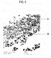
- FIG. 5 is a photograph of the exhaust gas purifying catalyst of this example taken using a transmission electron microscope (TEM).
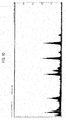
- FIG. 6 shows an energy dispersive X-ray analysis of area A shown in FIG. 5 .
- FIG. 7 shows an energy dispersive X-ray analysis of area B shown in FIG. 5 .
- FIG. 8 is a transmission electron micrograph of area A shown in FIG. 5 .
- Ce-Z type oxide particles of a fluorite type oxide and LaFeO 3 particles of a perovskite type oxide were turned out to be present in interference fringe areas in FIG. 8 owing to additional observation by X-ray photoelectron spectroscopy analysis (XPS). The same observation result was obtained in each example.
- a Ce-Z type oxide (72% by mass of ZrO 2 -21 % by mass of CeO 2 -5% by mass of Nd 2 O 3 -2% by mass of La 2 O 3 ) was impregnated with a lactic acid solution containing lanthanum and a lactic acid solution containing nickel, and was then kept under reduced pressure for an hour. After that, the oxide was baked in air at 400°C for two hours and further at 700°C for five hours, so that an exhaust gas purifying catalyst of this example was obtained.
- the mass ratio of LaNiO 3 to the Ce-Z type oxide is 30 to 70.
- the particle diameter was observed and measured with the scanning electron microscope (SEM). Table 1 shows a part of the specification of the exhaust gas purifying catalyst of this example.
- a Ce-Z type oxide (72% by mass of ZrO 2 -21% by mass of CeO 2 -5% by mass of Nd 2 O 3 -2% by mass of La 2 O 3 ) was impregnated with a lactic acid solution containing lanthanum and a lactic acid solution containing manganese, and was then kept under reduced pressure for an hour. After that, the oxide was baked in air at 400°C for two hours and further at 700°C for five hours, so that an exhaust gas purifying catalyst of this example was obtained.
- the mass ratio of LaMnO 3 to the Ce-Z type oxide is 30 to 70.
- the particle diameter was observed and measured with the scanning electron microscope (SEM). Table 1 shows a part of the specification of the exhaust gas purifying catalyst of this example.
- a Ce-Z type oxide (70% by mass of ZrO 2 -20% by mass of CeO 2 -10% by mass of Nd 2 O 3 ) was impregnated with a lactic acid solution containing lanthanum, a lactic acid solution containing strontium and a lactic acid solution containing iron, and was then kept under reduced pressure for an hour. After that, the oxide was baked in air at 400°C for two hours and further at 700°C for five hours, so that an exhaust gas purifying catalyst of this example was obtained.
- the mass ratio of La 0.8 Sr 0.2 FeO 3 to the Ce-Z type oxide is 30 to 70.
- the particle diameter was observed and measured with the scanning electron microscope (SEM). Table 1 shows a part of the specification of the exhaust gas purifying catalyst of this example.
- a Ce-Z type oxide (70% by mass of ZrO 2 -20% by mass of CeO 2 -10% by mass of Nd 2 0 3 ) was impregnated with a lactic acid solution containing lanthanum, a lactic acid solution containing iron and a lactic acid solution containing manganese, and was then kept under reduced pressure for an hour. After that, the oxide was baked in air at 400°C for two hours and further at 700°C for five hours, so that an exhaust gas purifying catalyst of this example was obtained.
- the mass ratio of LaFe 0.8 Mn 0.2 O 3 to the Ce-Z type oxide is 30 to 70.
- the particle diameter was observed and measured with the scanning electron microscope (SEM). Table 1 shows a part of the specification of the exhaust gas purifying catalyst of this example.
- a Ce-Z type oxide (70% by mass of ZrO 2 -20% by mass of CeO 2 -10% by mass of Nd 2 O 3 ) was impregnated with a lactic acid solution containing lanthanum, a lactic acid solution containing iron and a lactic acid solution containing nickel, and was then kept under reduced pressure for an hour. After that, the oxide was baked in air at 400°C for two hours and further at 700°C for five hours, so that an exhaust gas purifying catalyst of this example was obtained.
- the mass ratio of LaFe 0.8 Ni 0.2 O 3 to the Ce-Z type oxide is 30 to 70.
- the particle diameter was observed and measured with the scanning electron microscope (SEM). Table 1 shows a part of the specification of the exhaust gas purifying catalyst of this example.
- a Ce-Z type oxide (72% by mass of ZrO 2 -21% by mass of CeO 2 -5% by mass of Nd 2 O 3 -2% by mass of La 2 O 3 ) was impregnated with a nitric acid solution containing lanthanum and a nitric acid solution containing iron, dried at 150°C overnight, and then pulverized with a mortar. After that, the oxide was baked in air at 400°C for two hours and further at 700°C for five hours, so that an oxide of this example was obtained.
- the mass ratio of LaFeO 3 to the Ce-Z type oxide is 30 to 70.
- the particle diameter was observed and measured with the scanning electron microscope (SEM). The particle diameter of aggregates of the LaFeO 3 particles was in the range from 100 nm to 500 nm. Table 1 shows a part of the specification of the exhaust gas purifying catalyst of this example.
- FIG. 9 is a photograph of the exhaust gas purifying catalyst of this example taken using a transmission electron microscope (TEM).
- FIG. 10 shows an energy dispersive X-ray analysis of area A shown in FIG. 9 .
- FIG. 11 shows an energy dispersive X-ray analysis of area B shown in FIG. 9 .
- the purifying performance was evaluated using the exhaust gas purifying catalyst of each example.
- Table 2 shows the obtained result.
- the content of CO 2 in the exhaust gas purifying catalyst of each example was measured with a quadrupole mass spectrometer under the following conditions.
- the CO conversion ratio was calculated by the following formula (I).
- a catalyst slurry was prepared in each example by use of the exhaust gas purifying catalyst of each example, and additionally boehmite alumina, nitric acid and deionized water, so that an exhaust gas purifying monolithic catalyst of each example was obtained.
- the concentration of CO in the exhaust gas purifying monolithic catalyst of each example was measured with an exhaust gas analyzer (MEXA-7100D, manufactured by HORIBA, LTD.) under the following conditions.
- the CO conversion ratio was calculated by the following formula (II).
- a catalyst slurry was prepared in each example by use of the exhaust gas purifying catalyst of each example, and additionally boehmite alumina, nitric acid and deionized water, so that an exhaust gas purifying monolithic catalyst of each example was obtained.
- the concentration of CO in the exhaust gas purifying monolithic catalyst of each example was measured with an exhaust gas analyzer (MEXA-7500D, manufactured by HORIBA, LTD.) under the following conditions.
- the CO conversion ratio was calculated by the formula (II).
- Example 1 and Example 4 provably have superior characteristics in the present circumstances.
- a catalyst slurry was prepared for each sample by use of a ceria-zirconia composite oxide, instead of the Ce-Z type oxide of Example 4, in a manner as to vary the amount of ceria thereof, and additionally by use of boehmite alumina, nitric acid and deionized water.
- an exhaust gas purifying monolithic catalyst of each sample was obtained.
- the concentration of CO in the exhaust gas purifying monolithic catalyst of each sample was measured with an exhaust gas analyzer (MEXA-9100, manufactured by HORIBA, LTD.) under the following conditions.
- the CO conversion ratio was calculated by the formula (II).
- FIG. 12 shows the obtained result.
- the amount of ceria (CeO 2 ) in the ceria-zirconia composite oxide is preferably greater than or equal to 5% by mass, more preferably greater than or equal to 20% by mass, still more preferably in the range from 5% to 90% by mass, particularly preferably in the range from 20% to 80% by mass.
Landscapes
- Chemical & Material Sciences (AREA)
- Engineering & Computer Science (AREA)
- Chemical Kinetics & Catalysis (AREA)
- Materials Engineering (AREA)
- Organic Chemistry (AREA)
- Combustion & Propulsion (AREA)
- Health & Medical Sciences (AREA)
- Ceramic Engineering (AREA)
- Toxicology (AREA)
- Mechanical Engineering (AREA)
- General Engineering & Computer Science (AREA)
- Biomedical Technology (AREA)
- Environmental & Geological Engineering (AREA)
- Analytical Chemistry (AREA)
- General Chemical & Material Sciences (AREA)
- Oil, Petroleum & Natural Gas (AREA)
- Catalysts (AREA)
- Crystallography & Structural Chemistry (AREA)
Abstract
Description
- The present invention relates to an exhaust gas purifying catalyst, an exhaust gas purifying monolith catalyst, and a method for manufacturing an exhaust gas purifying catalyst, and particularly, relates to an exhaust gas purifying catalyst having an ability to highly purify exhaust gas components, an exhaust gas purifying monolith catalyst, and a method for manufacturing an exhaust gas purifying catalyst.
- Research and development of purifying catalysts not using noble metal as an essential component, are being carried out. There is known an exhaust gas purifying catalyst including a perovskite type composite oxide phase, which includes a rare earth element and a transition metal element and employs a perovskite type composite oxide in which part of the transition metal element is substituted with zirconium (refer to Patent Literature 1).
- Further, there are known catalysts, such as a PM oxidation catalyst and an exhaust gas purifying catalyst, having an ability to highly store and release oxygen under low temperature and retain the ability for a long period of time (for example, refer to Patent Literature 2). Such catalysts include a composite oxide that has a perovskite type structure and contains a material with a high oxygen storage and release capacity at low temperature and a material with high oxygen mobility.
-
- Patent Literature 1: Japanese Patent Unexamined Publication No.
2005-306618 - Patent Literature 2: Japanese Patent Unexamined Publication No.
2009-131774 - However, the conventional exhaust gas purifying catalysts as described in Patent Literature I and
Patent Literature 2 do not have a sufficient exhaust gas purifying ability. - The present invention has been accomplished in view of the conventional problem. An object of the present invention is to provide an exhaust gas purifying catalyst having a high purifying ability even if noble metal is not used as an essential component, an exhaust gas purifying monolith catalyst, and a method for manufacturing an exhaust gas purifying catalyst.
- The inventors of the present invention devoted themselves to continuous studies to achieve the object described above. As a result, the inventors accomplished their goals and completed the present invention by supporting the oxide represented by formula (1) on an oxide having an oxygen storage and release capacity.
LaxM1-xM'O3-δ (1)
(wherein La represents lanthanum, M represents at least one element selected from the group consisting of barium (Ba), strontium (Sr) and calcium (Ca), M' represents at least one element selected from the group consisting of iron (Fe), cobalt (Co), nickel (Ni) and manganese (Mn), δ represents an oxygen deficiency amount, and x and δ fulfill conditions represented by 0 < x ≤ 1 and 0 ≤ δ ≤1, respectively.) - Namely, the exhaust gas purifying catalyst according to the present invention includes the oxide having the oxygen storage and release capacity, and the oxide represented by the formula (1) supported on the oxide having the oxygen storage and release capacity.
LaxM1-xM'O3-δ (1)
(wherein La represents lanthanum, M represents at least one element selected from the group consisting of barium (Ba), strontium (Sr) and calcium (Ca), M' represents at least one element selected from the group consisting of iron (Fe), cobalt (Co), nickel (Ni) and manganese (Mn), δ represents an oxygen deficiency amount, and x and δ fulfill conditions represented by 0 < x ≤ 1 and 0 ≤ δ ≤1, respectively.) - An exhaust gas purifying monolithic catalyst according to the present invention includes a catalyst layer that contains the exhaust gas purifying catalyst described above and is formed in an exhaust gas flow path of a monolithic substrate.
- A method for manufacturing the exhaust gas purifying catalyst described above according to the present invention includes impregnating the oxide having the oxygen storage and release capacity with a solution containing carboxylic acid lanthanum salt and at least one carboxylic acid metal salt selected from the group consisting of carboxylic acid barium salt, carboxylic acid strontium salt, carboxylic acid calcium salt, carboxylic acid iron salt, carboxylic acid cobalt salt, carboxylic acid nickel salt and carboxylic acid manganese salt, and supporting the carboxylic acid lanthanum salt and the carboxylic acid metal salt on the oxide having the oxygen storage and release capacity in a manner such that the ambient atmosphere of the solution is subjected to reduced pressure lower than atmospheric pressure.
- According to the present invention, the oxide represented by the formula (1) is supported on the oxide having the oxygen storage and release capacity.
LaxM1-xM'O3-δ (1)
(wherein La represents lanthanum, M represents at least one element selected from the group consisting of barium (Ba), strontium (Sr) and calcium (Ca), M' represents at least one element selected from the group consisting of iron (Fe), cobalt (Co), nickel (Ni) and manganese (Mn), δ represents an oxygen deficiency amount, and x and δ fulfill conditions represented by 0 < x ≤ 1 and 0 ≤δ ≤1, respectively.) - Accordingly, the present invention can provide; the exhaust gas purifying catalyst having a high purifying ability even if noble metal is not used as an essential component, the exhaust gas purifying monolith catalyst, and the method for manufacturing the exhaust gas purifying catalyst.
-
- [
FIG 1] FIG. 1 is a schematic configuration diagram showing an exhaust gas purifying catalyst according to a first embodiment. - [
FIG. 2] FIG. 2 is an explanatory view of an estimated reaction mechanism. - [
FIG. 3] FIG. 3 is a schematic configuration diagram showing a conventional exhaust gas purifying catalyst. - [
FIG. 4] FIG. 4 is a schematic configuration diagram showing an exhaust gas purifying monolithic catalyst according to a third embodiment. - [
FIG. 5] FIG. 5 is a transmission electron micrograph of an exhaust gas purifying catalyst of Example 1. - [
FIG 6] FIG. 6 shows an energy dispersive X-ray analysis of area A shown inFIG. 5 . - [
FIG. 7] FIG. 7 shows an energy dispersive X-ray analysis of area B shown inFIG. 5 . - [
FIG 8] FIG. 8 is a transmission electron micrograph of area A shown inFIG. 5 . - [
FIG 9] FIG. 9 is a transmission electron micrograph of an exhaust gas purifying catalyst of Comparative Example 1. - [
FIG 10] FIG. 10 shows an energy dispersive X-ray analysis of area A shown inFIG. 9 . - [
FIG 11] FIG. 11 shows an energy dispersive X-ray analysis of area B shown inFIG. 9 . - [
FIG. 12] FIG. 12 is a graph showing a relationship between CO conversion ratio and the amount of ceria in a ceria-zirconia composite oxide. - Hereinafter, an exhaust gas purifying catalyst, an exhaust gas purifying monolith catalyst, and a method for manufacturing an exhaust gas purifying catalyst will be explained in detail.
- First, an exhaust gas purifying catalyst according to an embodiment of the present invention is explained in detail with reference to the drawings.
FIG. 1 is a schematic configuration diagram showing an exhaust gas purifying catalyst according to a first embodiment. As shown in the figure, the exhaust gas purifyingcatalyst 1 according to the first embodiment includesoxides 2 having an oxygen storage and release capacity, andoxides 4a represented by the following formula (1) supported on theoxides 2. A typical particle diameter of theoxides 4a is in the range from 3 nm to 10 nm. Note that for reference,oxides 4b represented by the formula (1) but which are not supported on theoxides 2 having the oxygen storage and release capacity, are also shown inFIG. 1 . A typical particle diameter of theoxides 4b is greater than 50 nm.
LaxM1-xM'O3-δ (1)
(wherein La represents lanthanum, M represents at least one element selected from the group consisting of barium (Ba), strontium (Sr) and calcium (Ca), M' represents at least one element selected from the group consisting of iron (Fe), cobalt (Co), nickel (Ni) and manganese (Mn), δ represents an oxygen deficiency amount, and x and δ fulfill the conditions represented by 0 < x ≤ 1 and 0 ≤δ ≤1, respectively.) - Here, the definition of "the oxides represented by the formula (1) are supported on the oxides having the oxygen storage and release capacity" according to the present invention is explained in detail below with reference to an example in which "oxides B are supported on oxides A."
- Aggregated oxides B distinguishable from oxides A, at the point of observing by a transmission electron microscope (TEM), do not correspond to oxides that are supported on the oxides A. On the other hand, aggregated oxides B indistinguishable from the oxides A at the point of observing with TEM, and oxides B from which a constituent element is detected together with a constituent element of the oxides A at the point of elemental analysis of the oxides A by energy dispersive X-ray analysis (EDX (measurement range: beam diameter of 5 nm)), correspond to oxides that are supported on the oxides A. Note that, as a matter of course, the observation of the oxides B with TEM at a higher magnification and by X-ray photoelectron spectroscopy analysis (XPS), is possible.
- The above-described configuration contributes to providing an exhaust gas purifying catalyst having a high purifying ability even if noble metal is not used as an essential component.
- In the present circumstances, the effect achieved by such an exhaust gas purifying catalyst is probably because of the following reaction mechanism. It should be noted that the case in which the effect is achieved because of any other mechanisms is obviously included within the scope of the present invention.
-
FIG. 2 is an explanatory view of the estimated reaction mechanism. As shown in the figure, in the exhaust gas purifyingcatalyst 1, theoxides 4a represented by the formula (1) supported on theoxides 2 having the oxygen storage and release capacity, function as active sites of the catalytic reaction. In this case, theoxides 2 having the oxygen storage and release capacity and supporting theoxides 4a thereon, store and release oxygen required for the catalytic reaction, so as to promote the catalytic reaction. The improvement of the oxygen storage and release capacity further improves purifying activation under low temperature. -
FIG. 3 is a schematic configuration diagram of a conventional exhaust gas purifying catalyst. In the conventional exhaust gas purifyingcatalyst 10 shown inFIG. 3 , theoxides 4b represented by the formula (1) are not supported on theoxides 2 but are present in an aggregated state. Theoxides 4b are made of aggregated particles, and the aggregate diameter thereof is typically in the range from 100 nm to 500 nm. This configuration hardly achieves the mechanism described above, and the preferred effect according to the present invention may thus hardly be obtained. - In the exhaust gas purifying catalyst according to the first embodiment, the particle diameter of the oxides having the oxygen storage and release capacity is preferably in the range from 1 nm to 50 nm, more preferably in the range from 5 nm to 20 nm. If the particle diameter of the oxides is less than 1 nm, the oxides having the oxygen storage and release capacity are likely to be aggregated and the preferred effect is not achieved. Further, if the particle diameter of the oxides is greater than 50 nm, the oxides can hardly support the oxides represented by the formula (1) thereon and the preferred effect is not achieved.
- In the exhaust gas purifying catalyst according to the first embodiment, the particle diameter of the oxides represented by the formula (1) supported on the oxides having the oxygen storage and release capacity, is preferably in the range from 1 nm to 30 nm, more preferably in the range from 3 nm to 10 nm. If the particle diameter of the oxides is less than 1 nm, the oxides having the oxygen storage and release capacity are likely to be aggregated and the preferred effect is not achieved. Further, if the particle diameter of the oxides is greater than 30 nm, the oxides represented by the formula (1) can hardly be supported and the preferred effect is not achieved. In particular, the particle diameter of the oxides is preferably less than or equal to 10 nm because the oxides can demonstrate a higher purifying ability.
- As described above, the oxides represented by the formula (1) can function as active sites of the catalytic reaction, and have more active sites when compared to other oxides of the same amount. Consequently, the particle diameter of the oxides represented by the formula (1) is preferably smaller than the particle diameter of the oxides having the oxygen storage and release capacity.
- In the description of the present invention, "the particle diameter" represents the greatest length between any two points on the circumference of the oxide particle (the observed plane) observed by observation means such as a scanning electron microscope (SEM) and TEM. However, the particle diameter is not limited to above ranges, and may of course have any length as long as the effect according to the present invention can be achieved effectively.
- In addition, the oxides having the oxygen storage and release capacity in the exhaust gas purifying catalyst according to the first embodiment, are preferably oxides containing at least one of cerium (Ce) and zirconium (Zr), more preferably composite oxides containing both cerium (Ce) and zirconium (Zr). The oxides containing cerium (Ce) are preferable because of their ability to store and release a large amount of oxygen. The oxides containing zirconium (Zr) are preferable because of their ability to store and release oxygen quickly. Thus, the composite oxides containing both cerium (Ce) and zirconium (Zr) are preferable because of their ability to store and release a large amount of oxygen quickly.
- Examples of the oxides containing cerium and zirconium include composite oxides containing zirconium, cerium, lanthanum and neodymium (Zr-Ce-La-Nd-Ox), composite oxides containing zirconium, cerium and neodymium (Zr-Ce-Nd-Ox), and composite oxides containing zirconium and lanthanum (Zr-La-Ox). However, the oxides are not limited to these examples. Namely, conventionally known materials may be used as long as the oxides have the oxygen storage and release capacity. For example, the oxides may be oxides containing cerium and zirconium, wherein part of cerium and zirconium is substituted with an alkali metal element, an alkaline-earth metal element or a rare earth element.
- Further, when the oxides having the oxygen storage and release capacity in the exhaust gas purifying catalyst according to the first embodiment are the composite oxides containing cerium (Ce) and zirconium (Zr), the content of cerium corresponding to the content of cerium oxide (CeO2) in the composite oxides is preferably greater than or equal to 5% by mass because this contributes to improving the CO conversion ratio. The content is more preferably greater than or equal to 20% by mass because this contributes to further improving the CO conversion ratio. More particularly, the content of cerium corresponding to the content of cerium oxide (CeO2) in the composite oxides is preferably from 5% by mass to 90% by mass inclusive, more preferably from 20% by mass to 80% by mass inclusive. If the content of cerium in the composite oxides is greater than 90% by mass in terms of cerium oxide (CeO2), the effect on the CO conversion ratio may be reduced.
- In addition, the oxides represented by the formula (1) in the exhaust gas purifying catalyst are preferably perovskite type oxides because perovskite type oxides have a crystal structure that enhances durability.
- Second, a method for manufacturing an exhaust gas purifying catalyst according to an embodiment of the present invention is explained in detail with reference to the exhaust gas purifying catalyst according to the above-described embodiment. However, the exhaust gas purifying catalyst according to the present invention is not limited to that manufactured by this method.
- The exhaust gas purifying catalyst according to the first embodiment may be manufactured by the following method.
- First, as for the oxides having the oxygen storage and release capacity, aggregates of fluorite type oxide particles containing cerium and zirconium are prepared.
- In addition, a solution is prepared containing carboxylic acid lanthanum salt, and at least one carboxylic acid metal salt selected from the group consisting of carboxylic acid barium salt, carboxylic acid strontium salt, carboxylic acid calcium salt, carboxylic acid iron salt, carboxylic acid cobalt salt, carboxylic acid nickel salt and carboxylic acid manganese salt, and is adjusted in a manner such that the composition of the oxides represented by the formula (1) meets a preferred condition.
- Next, the prepared oxides having the oxygen storage and release capacity are impregnated with the solution thus obtained. In this case, the oxides are impregnated with the solution in a manner such that the ambient atmosphere of the solution is subjected to reduced pressure lower than atmospheric pressure. This is achieved by use of, for example, an aspirator, to degas fine pores of the oxides having the oxygen storage and release capacity so as to allow the impregnation and support of the solution to smoothly proceed.
- Then, the oxides having the oxygen storage and release capacity, which are impregnated with the carboxylic acid lanthanum salt and the carboxylic acid metal salt and support those thereon, are dried, provisionally baked approximately at 400°C, and then fully baked approximately at 700°C, so as to obtain the exhaust gas purifying catalyst according to the first embodiment.
- If, for example, nitrate lanthanum salt and nitrate metal salt are only included, the fine pores of the oxides are easily impregnated therewith because of their little viscosity, but these kinds of salt are easily moved as the solution evaporates at the time of drying and baking, and can hardly be supported on the oxides. On the other hand, when carboxylic acid lanthanum salt and carboxylic acid metal salt are used, the fine pores of the oxides can be impregnated therewith by degassing, since these kinds of salt form a metallic complex salt and have higher viscosity. In addition, such a metallic complex salt is hardly moved in association with the evaporation of the solution, and is supported on the oxides at the time of drying and baking due to its viscous property.
- Examples of carboxylic acid include acid having 1 to 4 carboxyl groups. For example, gluconic acid, malic acid, maleic acid, lactic acid, succinic acid, fumaric acid, propionic acid, methacrylic acid, acrylic acid, citric acid, tartaric acid, itaconic acid, formic acid, acetic acid and malonic acid, may be used. Among these, lactic acid is particularly preferable.
- Third, an exhaust gas purifying monolithic catalyst according to an embodiment of the present invention is explained in detail with reference to the drawings.
FIG. 4 is a schematic configuration diagram showing an exhaust gas purifying monolithic catalyst according to a third embodiment. The exhaust gas purifyingmonolithic catalyst 10 according to the third embodiment includes catalyst layers 12 containing the exhaust gas purifying catalyst according to the first embodiment, wherein the catalyst layers 12 are formed in exhaust gas flow paths 14a of amonolithic substrate 14. The monolithic substrate may be a substrate containing a heat-resistant material, which is, for example, a ceramic such as cordierite or a metal such as ferric stainless steel. - The above-described configuration contributes to providing an exhaust gas purifying catalyst having a high purifying ability even if noble metal is not used as an essential component. In particular, such a catalyst can demonstrate a high purifying ability even if the flow of exhaust gas is fast.
- Hereinafter, the present invention is explained in more detail with reference to examples and a comparative example; however, the present invention is not limited to these examples.
- A Ce-Z type oxide (72% by mass of ZrO2-21% by mass of CeO2-5% by mass of Nd2O3-2% by mass of La2O3) was impregnated with a lactic acid solution containing lanthanum and a lactic acid solution containing iron, and was then kept under reduced pressure for an hour. After that, the oxide was baked in air at 400°C for two hours and further at 700°C for five hours, so that an exhaust gas purifying catalyst of this example was obtained. Here, the mass ratio of LaFeO3 to the Ce-Z type oxide is 30 to 70. The particle diameter was observed and measured with a scanning electron microscope (SEM). Table 1 shows a part of the specification of the exhaust gas purifying catalyst of this example.
-
FIG. 5 is a photograph of the exhaust gas purifying catalyst of this example taken using a transmission electron microscope (TEM).FIG. 6 shows an energy dispersive X-ray analysis of area A shown inFIG. 5 .FIG. 7 shows an energy dispersive X-ray analysis of area B shown inFIG. 5 .FIG. 8 is a transmission electron micrograph of area A shown inFIG. 5 . - As shown in
FIG. 6 , in the particles with the diameter of approximately 10 nm observed in area A by energy dispersive X-ray (EDX) elemental analysis, zirconium (Zr) and cerium (Ce) were mainly observed, and lanthanum (La), neodymium (Nd) and iron (Fe) were also observed. In addition, as shown inFIG. 7 , in the particles with the diameter of approximately greater than 50 nm observed in area B, iron (Fe) and lanthanum (La) were mainly observed. With regard to the observation in interference fringe areas inFIG. 8 , Ce-Z type oxide particles of a fluorite type oxide and LaFeO3 particles of a perovskite type oxide were turned out to be present in interference fringe areas inFIG. 8 owing to additional observation by X-ray photoelectron spectroscopy analysis (XPS). The same observation result was obtained in each example. - A Ce-Z type oxide (72% by mass of ZrO2-21 % by mass of CeO2-5% by mass of Nd2O3-2% by mass of La2O3) was impregnated with a lactic acid solution containing lanthanum and a lactic acid solution containing nickel, and was then kept under reduced pressure for an hour. After that, the oxide was baked in air at 400°C for two hours and further at 700°C for five hours, so that an exhaust gas purifying catalyst of this example was obtained. Here, the mass ratio of LaNiO3 to the Ce-Z type oxide is 30 to 70. The particle diameter was observed and measured with the scanning electron microscope (SEM). Table 1 shows a part of the specification of the exhaust gas purifying catalyst of this example.
- A Ce-Z type oxide (72% by mass of ZrO2-21% by mass of CeO2-5% by mass of Nd2O3-2% by mass of La2O3) was impregnated with a lactic acid solution containing lanthanum and a lactic acid solution containing manganese, and was then kept under reduced pressure for an hour. After that, the oxide was baked in air at 400°C for two hours and further at 700°C for five hours, so that an exhaust gas purifying catalyst of this example was obtained. Here, the mass ratio of LaMnO3 to the Ce-Z type oxide is 30 to 70. The particle diameter was observed and measured with the scanning electron microscope (SEM). Table 1 shows a part of the specification of the exhaust gas purifying catalyst of this example.
- A Ce-Z type oxide (70% by mass of ZrO2-20% by mass of CeO2-10% by mass of Nd2O3) was impregnated with a lactic acid solution containing lanthanum, a lactic acid solution containing strontium and a lactic acid solution containing iron, and was then kept under reduced pressure for an hour. After that, the oxide was baked in air at 400°C for two hours and further at 700°C for five hours, so that an exhaust gas purifying catalyst of this example was obtained. Here, the mass ratio of La0.8Sr0.2FeO3 to the Ce-Z type oxide is 30 to 70. The particle diameter was observed and measured with the scanning electron microscope (SEM). Table 1 shows a part of the specification of the exhaust gas purifying catalyst of this example.
- A Ce-Z type oxide (70% by mass of ZrO2-20% by mass of CeO2-10% by mass of Nd203) was impregnated with a lactic acid solution containing lanthanum, a lactic acid solution containing iron and a lactic acid solution containing manganese, and was then kept under reduced pressure for an hour. After that, the oxide was baked in air at 400°C for two hours and further at 700°C for five hours, so that an exhaust gas purifying catalyst of this example was obtained. Here, the mass ratio of LaFe0.8Mn0.2O3 to the Ce-Z type oxide is 30 to 70. The particle diameter was observed and measured with the scanning electron microscope (SEM). Table 1 shows a part of the specification of the exhaust gas purifying catalyst of this example.
- A Ce-Z type oxide (70% by mass of ZrO2-20% by mass of CeO2-10% by mass of Nd2O3) was impregnated with a lactic acid solution containing lanthanum, a lactic acid solution containing iron and a lactic acid solution containing nickel, and was then kept under reduced pressure for an hour. After that, the oxide was baked in air at 400°C for two hours and further at 700°C for five hours, so that an exhaust gas purifying catalyst of this example was obtained. Here, the mass ratio of LaFe0.8Ni0.2O3 to the Ce-Z type oxide is 30 to 70. The particle diameter was observed and measured with the scanning electron microscope (SEM). Table 1 shows a part of the specification of the exhaust gas purifying catalyst of this example.
- A Ce-Z type oxide (72% by mass of ZrO2-21% by mass of CeO2-5% by mass of Nd2O3-2% by mass of La2O3) was impregnated with a nitric acid solution containing lanthanum and a nitric acid solution containing iron, dried at 150°C overnight, and then pulverized with a mortar. After that, the oxide was baked in air at 400°C for two hours and further at 700°C for five hours, so that an oxide of this example was obtained. Here, the mass ratio of LaFeO3 to the Ce-Z type oxide is 30 to 70. The particle diameter was observed and measured with the scanning electron microscope (SEM). The particle diameter of aggregates of the LaFeO3 particles was in the range from 100 nm to 500 nm. Table 1 shows a part of the specification of the exhaust gas purifying catalyst of this example.
-
FIG. 9 is a photograph of the exhaust gas purifying catalyst of this example taken using a transmission electron microscope (TEM).FIG. 10 shows an energy dispersive X-ray analysis of area A shown inFIG. 9 .FIG. 11 shows an energy dispersive X-ray analysis of area B shown inFIG. 9 . - As shown in
FIG. 10 , in the aggregates observed in area A by energy dispersive X-ray (EDX) elemental analysis, iron (Fe) and lanthanum (La) were mainly observed. Further, as shown inFIG. 11 , in the matrix observed in area B, zirconium (Zr) and cerium (Ce) were mainly observed.[Table 1] Unit: nm Unit: nm Active Site Ce-Zr Type Composite Oxide Present in Ce Zr Type Composite Oxide Composition Particle Diameter (Small) Particle Diameter (Large) Composition Particle Diameter (Small) Particle Diameter (Large) EXAMPLE 1 LaFeO 32 10 Ce-Zr-La-Nd- Ox 10 30 EXAMPLE 2 LaNiO3 3 10 Ce-Zr-La-Nd- Ox 10 30 EXAMPLE 3 LaMnO3 3 10 Ce-Zr-La-Nd- Ox 10 30 EXAMPLE 4 La0.8Sr0.2FeO3 5 10 Ce-Zr-Nd- Ox 5 30 EXAMPLE 5 LaFe0.8Mn0.2O3 3 10 Ce-Zr-Nd- Ox 5 30 EXAMPLE 6 LaFe0.8Ni0.2O3 5 10 Ce-Zr-Nd- Ox 5 30 COMPARATIVE EXAMPLE 1 LaFeO3 N.D. N.D. Ce-Zr-La-Nd- Ox 10 30 N.D.: Non Detect - The purifying performance was evaluated using the exhaust gas purifying catalyst of each example. Table 2 shows the obtained result.
- The content of CO2 in the exhaust gas purifying catalyst of each example was measured with a quadrupole mass spectrometer under the following conditions. The CO conversion ratio was calculated by the following formula (I).
-
- · Amount of catalyst: 0.2 g (powder)
- · Flow rate: 50 cm3/min
- · Gas composition: 0.4% by volume of CO; 0.2% by volume of O2; balance, He
- A catalyst slurry was prepared in each example by use of the exhaust gas purifying catalyst of each example, and additionally boehmite alumina, nitric acid and deionized water, so that an exhaust gas purifying monolithic catalyst of each example was obtained. The concentration of CO in the exhaust gas purifying monolithic catalyst of each example was measured with an exhaust gas analyzer (MEXA-7100D, manufactured by HORIBA, LTD.) under the following conditions. The CO conversion ratio was calculated by the following formula (II).
-
- · Content of catalyst: 119 cm3
- · Gas flow rate: 40 L/min
- · Gas composition (stoichiometry): 0.6% by volume of O2; 0.6% by volume of CO; 1000 volume ppm of NO; 1665 volume ppmC of HC; 0.2% by volume of H2; 10% by volume of H2O; 13.9% by volume of CO2

- A catalyst slurry was prepared in each example by use of the exhaust gas purifying catalyst of each example, and additionally boehmite alumina, nitric acid and deionized water, so that an exhaust gas purifying monolithic catalyst of each example was obtained. The concentration of CO in the exhaust gas purifying monolithic catalyst of each example was measured with an exhaust gas analyzer (MEXA-7500D, manufactured by HORIBA, LTD.) under the following conditions. The CO conversion ratio was calculated by the formula (II).
-
· Use of engine manufactured by NISSAN MOTOR CO., LTD.
· Content of catalyst: 119 cm3
· Gas flow rate: 60 m3/h
. Gas composition (stoichiometry): approximately 2000 volume ppmC of HC; approximately 0.54% by volume of CO; approximately 1500 volume ppm of NO; approximately 0.56% by volume of O2; 14.6% by volume of O2[Table 2] Powder Evaluation Laboratory Evaluation Bench Test Evaluation CO Conversion Ratio (%) CO Conversion Ratio (%) CO Conversion Ratio (%) (Catalyst Inlet Temperature 350°C) (Catalyst Inlet Temperature 480°C) (Catalyst Inlet Temperature 480°C) EXAMPLE 1 61 31 45 EXAMPLE 2 - 20 - EXAMPLE 3 - 25 - EXAMPLE 4 - 80 88 EXAMPLE 5 - 25 36 EXAMPLE 6 - 21 31 COMPARATIVE EXAMPLE 1 47 15 - - As is apparent from Table 1 and Table 2, evaluation revealed that Examples 1 to 6 relating to the scope of the present invention have a higher conversion ratio of carbon monoxide and demonstrate higher oxidation performance than Comparative Example 1 excluded in the present invention. In particular, Example 1 and Example 4 provably have superior characteristics in the present circumstances.
- A catalyst slurry was prepared for each sample by use of a ceria-zirconia composite oxide, instead of the Ce-Z type oxide of Example 4, in a manner as to vary the amount of ceria thereof, and additionally by use of boehmite alumina, nitric acid and deionized water. With the catalyst slurries having the different amounts of ceria, an exhaust gas purifying monolithic catalyst of each sample was obtained. The concentration of CO in the exhaust gas purifying monolithic catalyst of each sample was measured with an exhaust gas analyzer (MEXA-9100, manufactured by HORIBA, LTD.) under the following conditions. The CO conversion ratio was calculated by the formula (II).
FIG. 12 shows the obtained result. -
- · Use of engine manufactured by NISSAN MOTOR CO., LTD.
- · Coating amount of catalyst: 268 g/L + DPR: 32 g/L
- · Gas flow rate: 60 m3/h
- · A/F amplitude: ±0.2, 1.0 Hz
- · Gas composition (stoichiometry): approximately 2000 volume ppmC of HC; approximately 0.54% by volume of CO; approximately 1500 volume ppm of NO; approximately 0.56% by volume of O2; 14.6% by volume of CO2
- As is apparent from
FIG. 12 , evaluation revealed that the amount of ceria (CeO2) in the ceria-zirconia composite oxide is preferably greater than or equal to 5% by mass, more preferably greater than or equal to 20% by mass, still more preferably in the range from 5% to 90% by mass, particularly preferably in the range from 20% to 80% by mass. -
- 1, 100
- Exhaust gas purifying catalyst
- 2
- Oxide having oxygen storage and release capacity
- 4a, 4b
- Oxide represented by formula (1)
- 10
- Exhaust gas purifying monolithic catalyst
- 12
- Catalyst layer
- 14
- Monolithic substrate
Claims (9)
- An exhaust gas purifying catalyst, comprising:an oxide having an oxygen storage and release capacity; andan oxide represented by formula (1) supported on the oxide having the oxygen storage and release capacity,
LaxM1-xM'O3-δ (1)
(wherein La represents lanthanum, M represents at least one element selected from the group consisting of barium (Ba), strontium (Sr) and calcium (Ca), M' represents at least one element selected from the group consisting of iron (Fe), cobalt (Co), nickel (Ni) and manganese (Mn), δ represents an oxygen deficiency amount, and x and δ fulfill conditions represented by 0 < x ≤ 1 and 0 ≤ δ ≤ 1, respectively). - The exhaust gas purifying catalyst according to claim 1,
wherein a particle diameter of the oxide having the oxygen storage and release capacity is in a range from 1 nm to 50 nm, and
a particle diameter of the oxide represented by the formula (1) is in a range from 1 nm to 30 nm. - The exhaust gas purifying catalyst according to claim 1 or 2,
wherein a particle diameter of the oxide having the oxygen storage and release capacity is in a range from 5 nm to 20 nm, and
a particle diameter of the oxide represented by the formula (1) is in a range from 3 nm to 10 nm. - The exhaust gas purifying catalyst according to any one of claims 1 to 3, wherein the oxide having the oxygen storage and release capacity is an oxide containing at least one of cerium and zirconium.
- The exhaust gas purifying catalyst according to any one of claims 1 to 4, wherein the oxide having the oxygen storage and release capacity is a composite oxide containing cerium and zirconium.
- The exhaust gas purifying catalyst according to claim 5, wherein a content of cerium corresponding to a content of cerium oxide (CeO2) in the composite oxide is greater than or equal to 5% by mass.
- The exhaust gas purifying catalyst according to claim 5 or 6, wherein a content of cerium corresponding to a content of cerium oxide (CeO2) in the composite oxide is greater than or equal to 20% by mass.
- An exhaust gas purifying monolithic catalyst, comprising:a catalyst layer containing the exhaust gas purifying catalyst according to any one of claims 1 to 7; anda monolithic substrate,the catalyst layer being formed in an exhaust gas flow path of the monolithic substrate.
- A method for manufacturing the exhaust gas purifying catalyst according to any one of claims 1 to 7, comprising:impregnating the oxide having the oxygen storage and release capacity with a solution containing carboxylic acid lanthanum salt and at least one carboxylic acid metal salt selected from the group consisting of carboxylic acid barium salt, carboxylic acid strontium salt, carboxylic acid calcium salt, carboxylic acid iron salt, carboxylic acid cobalt salt, carboxylic acid nickel salt and carboxylic acid manganese salt; andsupporting the carboxylic acid lanthanum salt and the carboxylic acid metal salt on the oxide having the oxygen storage and release capacity in a manner such that an ambient atmosphere of the solution is subjected to reduced pressure lower than atmospheric pressure.
Applications Claiming Priority (2)
| Application Number | Priority Date | Filing Date | Title |
|---|---|---|---|
| JP2011077444 | 2011-03-31 | ||
| PCT/JP2012/058122 WO2012133526A1 (en) | 2011-03-31 | 2012-03-28 | Exhaust gas purification catalyst, exhaust gas purification monolith catalyst, and process for producing exhaust gas purification catalyst |
Publications (3)
| Publication Number | Publication Date |
|---|---|
| EP2692432A1 true EP2692432A1 (en) | 2014-02-05 |
| EP2692432A4 EP2692432A4 (en) | 2014-10-29 |
| EP2692432B1 EP2692432B1 (en) | 2019-11-13 |
Family
ID=46931235
Family Applications (1)
| Application Number | Title | Priority Date | Filing Date |
|---|---|---|---|
| EP12763126.5A Active EP2692432B1 (en) | 2011-03-31 | 2012-03-28 | Exhaust gas purification catalyst, exhaust gas purification monolith catalyst, and process for producing exhaust gas purification catalyst |
Country Status (5)
| Country | Link |
|---|---|
| US (1) | US9101914B2 (en) |
| EP (1) | EP2692432B1 (en) |
| JP (1) | JP5720772B2 (en) |
| CN (1) | CN103402630B (en) |
| WO (1) | WO2012133526A1 (en) |
Cited By (3)
| Publication number | Priority date | Publication date | Assignee | Title |
|---|---|---|---|---|
| EP2893979A4 (en) * | 2012-09-10 | 2015-10-14 | Nissan Motor | Exhaust gas purification catalyst, exhaust gas purification monolith catalyst, and method for producing exhaust gas purification catalyst |
| EP3108961A4 (en) * | 2014-02-18 | 2017-03-22 | Nissan Motor Co., Ltd | Exhaust gas purification catalyst and production method thereof |
| WO2022034373A1 (en) * | 2020-08-12 | 2022-02-17 | Neo Performance Materials (Singapore) Pte. Ltd. | Oxygen storage capacity enhanced compositions |
Families Citing this family (12)
| Publication number | Priority date | Publication date | Assignee | Title |
|---|---|---|---|---|
| DE102011107702A1 (en) * | 2011-07-14 | 2013-01-17 | Sasol Germany Gmbh | Process for the preparation of composites of alumina and cerium / zirconium mixed oxides |
| EP2878368B1 (en) | 2013-11-29 | 2019-05-22 | Umicore Ag & Co. Kg | Oxygen storage materials |
| EP2878359B1 (en) * | 2013-11-29 | 2016-04-13 | Umicore Ag & Co. Kg | Use of mixed oxides as oxygen storage components |
| JP6362040B2 (en) * | 2014-05-13 | 2018-07-25 | 日産自動車株式会社 | Exhaust gas purification catalyst |
| WO2015173880A1 (en) * | 2014-05-13 | 2015-11-19 | 日産自動車株式会社 | Hydrogen-generating catalyst, and exhaust gas purification catalyst |
| JP5892712B2 (en) * | 2014-07-15 | 2016-03-23 | 株式会社キャタラー | Exhaust gas purification catalyst |
| US9662639B2 (en) * | 2015-05-11 | 2017-05-30 | University Of Wyoming | Catalytic effects of oxygen carrier based chemical-looping reforming of CH4 with CO2 |
| EP4098357A1 (en) | 2016-11-14 | 2022-12-07 | Research Triangle Institute | Perovskite three-way catalyst and use thereof |
| CN109647420B (en) * | 2018-12-27 | 2021-01-05 | 中国科学院广州地球化学研究所 | Calcium-doped lanthanum perovskite cobaltite type oxide for thermal catalytic oxidation of toluene and preparation method and application thereof |
| EP3888787A4 (en) * | 2019-09-04 | 2022-05-04 | Grirem Advanced Materials Co., Ltd. | Rare earth manganese/cerium-zirconium-based composite compound, preparation method therefor and application thereof |
| CN118317831A (en) * | 2022-02-03 | 2024-07-09 | 庄信万丰股份有限公司 | Surface modified ceria-zirconia mixed oxide compounds for gasoline exhaust gas applications |
| CN114917916A (en) * | 2022-05-30 | 2022-08-19 | 昆明理工大学 | Oxygen carrier with high oxygen storage capacity and high stability and preparation method thereof |
Citations (1)
| Publication number | Priority date | Publication date | Assignee | Title |
|---|---|---|---|---|
| US20100233045A1 (en) * | 2009-03-16 | 2010-09-16 | Gm Global Technology Operations, Inc. | Sulfur tolerant perovskite supported catalysts |
Family Cites Families (20)
| Publication number | Priority date | Publication date | Assignee | Title |
|---|---|---|---|---|
| JPH0722705B2 (en) | 1986-03-20 | 1995-03-15 | 松下電器産業株式会社 | Method for producing oxidation catalyst |
| FR2631858A1 (en) | 1988-05-24 | 1989-12-01 | Solvay | CATALYTIC COMPOSITIONS, PROCESS FOR THEIR PRODUCTION AND METHOD FOR HYDROGENATION OF CHLOROFLUORALCENES USING THE SAME |
| US5243103A (en) | 1988-05-24 | 1993-09-07 | Solvay S.A. | Process for obtaining catalytic compositions and process for hydrogenation of chlorofluoroalkenes by means of these compositions |
| DE69206707T2 (en) | 1991-07-29 | 1996-05-09 | Daihatsu Motor Co Ltd | Exhaust gas purification catalyst and process for its manufacture |
| JP3260148B2 (en) | 1991-07-29 | 2002-02-25 | ダイハツ工業株式会社 | Exhaust gas purification catalyst |
| JPH07136518A (en) | 1993-11-22 | 1995-05-30 | Nissan Motor Co Ltd | Exhaust gas purifying catalyst |
| WO2001030494A1 (en) | 1999-10-27 | 2001-05-03 | Idemitsu Kosan Co., Ltd. | Hydrotreating catalyst for hydrocarbon oil, carrier for the same and method for hydrotreating of hydrocarbon oil |
| JP2001276626A (en) | 2000-04-03 | 2001-10-09 | Idemitsu Kosan Co Ltd | Hydrogenation catalyst and manufacturing method thereof and hydrogenating method of hydrocarbon oil |
| JP2002049963A (en) * | 2000-08-04 | 2002-02-15 | Kubota Corp | Merchandise delivery device for automatic vending machine |
| JPWO2002049963A1 (en) | 2000-12-19 | 2004-04-22 | 出光興産株式会社 | Titanium compound, titanium-containing aqueous solution and method for producing the same |
| JP4263470B2 (en) | 2002-10-11 | 2009-05-13 | ダイハツ工業株式会社 | Exhaust gas purification catalyst and method for producing the same |
| JP4604211B2 (en) | 2004-04-16 | 2011-01-05 | Dowaエレクトロニクス株式会社 | Perovskite complex oxide, method for producing the same, and catalyst using the same |
| JP2006258911A (en) | 2005-03-15 | 2006-09-28 | Denon Ltd | Apparatus and method for playback |
| JP2006256911A (en) * | 2005-03-17 | 2006-09-28 | Tosoh Corp | Preparation method of ceria-zirconia-based oxide |
| JP4928931B2 (en) | 2006-12-20 | 2012-05-09 | 日本電工株式会社 | Ceria-zirconia composite oxide and method for producing the same |
| JP4985299B2 (en) | 2007-10-10 | 2012-07-25 | マツダ株式会社 | Exhaust gas component purification catalyst material and particulate filter with the catalyst material |
| EP2055365B1 (en) | 2007-10-10 | 2018-02-28 | Mazda Motor Corporation | Catalyst-supported particulate filter |
| JP2009131774A (en) | 2007-11-30 | 2009-06-18 | Nissan Motor Co Ltd | Pm oxidation catalyst and exhaust gas cleaning catalyst comprising the same |
| FR2942624B1 (en) | 2009-03-02 | 2011-03-18 | Rhodia Operations | COMPOSITION COMPRISING LANTHAN PEROVSKITE ON AN ALUMINUM OR ALUMINUM OXYHYDROXIDE SUPPORT, PREPARATION METHOD AND USE IN CATALYSIS |
| US8950174B2 (en) * | 2010-09-02 | 2015-02-10 | Basf Se | Catalysts for gasoline lean burn engines with improved NH3-formation activity |
-
2012
- 2012-03-28 US US14/006,841 patent/US9101914B2/en active Active
- 2012-03-28 CN CN201280010755.9A patent/CN103402630B/en active Active
- 2012-03-28 WO PCT/JP2012/058122 patent/WO2012133526A1/en active Application Filing
- 2012-03-28 EP EP12763126.5A patent/EP2692432B1/en active Active
- 2012-03-28 JP JP2013507669A patent/JP5720772B2/en active Active
Patent Citations (1)
| Publication number | Priority date | Publication date | Assignee | Title |
|---|---|---|---|---|
| US20100233045A1 (en) * | 2009-03-16 | 2010-09-16 | Gm Global Technology Operations, Inc. | Sulfur tolerant perovskite supported catalysts |
Non-Patent Citations (1)
| Title |
|---|
| See also references of WO2012133526A1 * |
Cited By (5)
| Publication number | Priority date | Publication date | Assignee | Title |
|---|---|---|---|---|
| EP2893979A4 (en) * | 2012-09-10 | 2015-10-14 | Nissan Motor | Exhaust gas purification catalyst, exhaust gas purification monolith catalyst, and method for producing exhaust gas purification catalyst |
| US9352301B2 (en) | 2012-09-10 | 2016-05-31 | Nissan Motor Co., Ltd. | Exhaust gas purification catalyst, exhaust gas purification monolith catalyst, and method for producing exhaust gas purification catalyst |
| EP3108961A4 (en) * | 2014-02-18 | 2017-03-22 | Nissan Motor Co., Ltd | Exhaust gas purification catalyst and production method thereof |
| US10245579B2 (en) | 2014-02-18 | 2019-04-02 | Nissan Motor Co., Ltd. | Exhaust gas purification catalyst and production method thereof |
| WO2022034373A1 (en) * | 2020-08-12 | 2022-02-17 | Neo Performance Materials (Singapore) Pte. Ltd. | Oxygen storage capacity enhanced compositions |
Also Published As
| Publication number | Publication date |
|---|---|
| EP2692432A4 (en) | 2014-10-29 |
| CN103402630B (en) | 2015-11-25 |
| EP2692432B1 (en) | 2019-11-13 |
| JP5720772B2 (en) | 2015-05-20 |
| US20140018235A1 (en) | 2014-01-16 |
| US9101914B2 (en) | 2015-08-11 |
| JPWO2012133526A1 (en) | 2014-07-28 |
| CN103402630A (en) | 2013-11-20 |
| WO2012133526A1 (en) | 2012-10-04 |
Similar Documents
| Publication | Publication Date | Title |
|---|---|---|
| EP2692432B1 (en) | Exhaust gas purification catalyst, exhaust gas purification monolith catalyst, and process for producing exhaust gas purification catalyst | |
| EP2893979B1 (en) | Exhaust gas purification catalyst, exhaust gas purification monolith catalyst, and method for producing exhaust gas purification catalyst | |
| EP1859851B1 (en) | Exhaust gas purifying catalyst and exhaust gas purifying method | |
| JP2006334490A (en) | Catalyst for cleaning exhaust gas | |
| JP7026530B2 (en) | Three-way catalyst for exhaust gas purification | |
| JP2010099638A (en) | Catalyst, catalyst for purifying exhaust gas, and method for manufacturing the catalyst | |
| JP2016168586A (en) | Core shell carrier and production method therefor, exhaust emission control catalyst using the core shell carrier and production method therefor, and exhaust emission control method using the exhaust emission control catalyst | |
| US9993805B2 (en) | Catalyst composition for purifying exhaust gas and exhaust gas purifying catalyst | |
| EP2221104A1 (en) | Purification catalyst | |
| WO2016158656A1 (en) | Exhaust purification catalyst | |
| WO2016143722A1 (en) | Core-shell support, method for producing the same, catalyst for purification of exhaust gas using the core- shell support, method for producing the same, and method for purification of exhaust gas using the catalyst for purification of exhaust gas | |
| JP4835028B2 (en) | Exhaust gas purification catalyst | |
| JP5794908B2 (en) | Exhaust gas purification catalyst and exhaust gas purification catalyst structure | |
| JP2010030823A (en) | Compound oxide and catalyst containing the compound oxide for cleaning exhaust gas | |
| JP6036276B2 (en) | Exhaust purification catalyst and method for producing exhaust purification catalyst | |
| JP5299603B2 (en) | Oxide complex precursor aqueous solution, oxide complex production method, oxide complex, exhaust gas purification catalyst including the oxide complex, and exhaust gas purification method using the exhaust gas purification catalyst | |
| JP5295196B2 (en) | Honeycomb base material for exhaust gas purification catalytic converter having excellent high temperature oxidation resistance and catalytic converter for exhaust gas purification | |
| JP4694220B2 (en) | Honeycomb base material for exhaust gas purification catalytic converter having excellent high temperature oxidation resistance and catalytic converter for exhaust gas purification | |
| JP2001232199A (en) | Exhaust gas cleaning catalyst | |
| JP5621109B2 (en) | Exhaust gas purification catalyst | |
| JP2016175010A (en) | Catalyst for exhaust purification, and exhaust purifying device and exhaust purification method using the same | |
| JP6639309B2 (en) | Exhaust gas purification catalyst | |
| JP5104352B2 (en) | Exhaust gas purification catalyst | |
| JP2017180453A (en) | Exhaust emission control device and its process of manufacture | |
| JP2018030100A (en) | Catalyst for exhaust purification, and method for producing the same, and catalyst converter for exhaust purification |
Legal Events
| Date | Code | Title | Description |
|---|---|---|---|
| PUAI | Public reference made under article 153(3) epc to a published international application that has entered the european phase |
Free format text: ORIGINAL CODE: 0009012 |
|
| 17P | Request for examination filed |
Effective date: 20131030 |
|
| AK | Designated contracting states |
Kind code of ref document: A1 Designated state(s): AL AT BE BG CH CY CZ DE DK EE ES FI FR GB GR HR HU IE IS IT LI LT LU LV MC MK MT NL NO PL PT RO RS SE SI SK SM TR |
|
| DAX | Request for extension of the european patent (deleted) | ||
| A4 | Supplementary search report drawn up and despatched |
Effective date: 20140930 |
|
| RIC1 | Information provided on ipc code assigned before grant |
Ipc: F01N 3/10 20060101ALI20140924BHEP Ipc: B01J 35/00 20060101ALI20140924BHEP Ipc: B01J 23/00 20060101ALI20140924BHEP Ipc: B01D 53/94 20060101ALI20140924BHEP Ipc: B01J 23/76 20060101AFI20140924BHEP Ipc: B01J 23/78 20060101ALI20140924BHEP |
|
| GRAP | Despatch of communication of intention to grant a patent |
Free format text: ORIGINAL CODE: EPIDOSNIGR1 |
|
| STAA | Information on the status of an ep patent application or granted ep patent |
Free format text: STATUS: GRANT OF PATENT IS INTENDED |
|
| INTG | Intention to grant announced |
Effective date: 20190806 |
|
| GRAS | Grant fee paid |
Free format text: ORIGINAL CODE: EPIDOSNIGR3 |
|
| GRAA | (expected) grant |
Free format text: ORIGINAL CODE: 0009210 |
|
| STAA | Information on the status of an ep patent application or granted ep patent |
Free format text: STATUS: THE PATENT HAS BEEN GRANTED |
|
| AK | Designated contracting states |
Kind code of ref document: B1 Designated state(s): AL AT BE BG CH CY CZ DE DK EE ES FI FR GB GR HR HU IE IS IT LI LT LU LV MC MK MT NL NO PL PT RO RS SE SI SK SM TR |
|
| REG | Reference to a national code |
Ref country code: CH Ref legal event code: EP Ref country code: AT Ref legal event code: REF Ref document number: 1201102 Country of ref document: AT Kind code of ref document: T Effective date: 20191115 |
|
| REG | Reference to a national code |
Ref country code: DE Ref legal event code: R096 Ref document number: 602012065664 Country of ref document: DE |
|
| REG | Reference to a national code |
Ref country code: IE Ref legal event code: FG4D |
|
| REG | Reference to a national code |
Ref country code: NL Ref legal event code: MP Effective date: 20191113 |
|
| REG | Reference to a national code |
Ref country code: LT Ref legal event code: MG4D |
|
| PG25 | Lapsed in a contracting state [announced via postgrant information from national office to epo] |
Ref country code: PL Free format text: LAPSE BECAUSE OF FAILURE TO SUBMIT A TRANSLATION OF THE DESCRIPTION OR TO PAY THE FEE WITHIN THE PRESCRIBED TIME-LIMIT Effective date: 20191113 Ref country code: LT Free format text: LAPSE BECAUSE OF FAILURE TO SUBMIT A TRANSLATION OF THE DESCRIPTION OR TO PAY THE FEE WITHIN THE PRESCRIBED TIME-LIMIT Effective date: 20191113 Ref country code: GR Free format text: LAPSE BECAUSE OF FAILURE TO SUBMIT A TRANSLATION OF THE DESCRIPTION OR TO PAY THE FEE WITHIN THE PRESCRIBED TIME-LIMIT Effective date: 20200214 Ref country code: NO Free format text: LAPSE BECAUSE OF FAILURE TO SUBMIT A TRANSLATION OF THE DESCRIPTION OR TO PAY THE FEE WITHIN THE PRESCRIBED TIME-LIMIT Effective date: 20200213 Ref country code: NL Free format text: LAPSE BECAUSE OF FAILURE TO SUBMIT A TRANSLATION OF THE DESCRIPTION OR TO PAY THE FEE WITHIN THE PRESCRIBED TIME-LIMIT Effective date: 20191113 Ref country code: SE Free format text: LAPSE BECAUSE OF FAILURE TO SUBMIT A TRANSLATION OF THE DESCRIPTION OR TO PAY THE FEE WITHIN THE PRESCRIBED TIME-LIMIT Effective date: 20191113 Ref country code: LV Free format text: LAPSE BECAUSE OF FAILURE TO SUBMIT A TRANSLATION OF THE DESCRIPTION OR TO PAY THE FEE WITHIN THE PRESCRIBED TIME-LIMIT Effective date: 20191113 Ref country code: FI Free format text: LAPSE BECAUSE OF FAILURE TO SUBMIT A TRANSLATION OF THE DESCRIPTION OR TO PAY THE FEE WITHIN THE PRESCRIBED TIME-LIMIT Effective date: 20191113 Ref country code: BG Free format text: LAPSE BECAUSE OF FAILURE TO SUBMIT A TRANSLATION OF THE DESCRIPTION OR TO PAY THE FEE WITHIN THE PRESCRIBED TIME-LIMIT Effective date: 20200213 Ref country code: PT Free format text: LAPSE BECAUSE OF FAILURE TO SUBMIT A TRANSLATION OF THE DESCRIPTION OR TO PAY THE FEE WITHIN THE PRESCRIBED TIME-LIMIT Effective date: 20200313 Ref country code: ES Free format text: LAPSE BECAUSE OF FAILURE TO SUBMIT A TRANSLATION OF THE DESCRIPTION OR TO PAY THE FEE WITHIN THE PRESCRIBED TIME-LIMIT Effective date: 20191113 |
|
| PG25 | Lapsed in a contracting state [announced via postgrant information from national office to epo] |
Ref country code: IS Free format text: LAPSE BECAUSE OF FAILURE TO SUBMIT A TRANSLATION OF THE DESCRIPTION OR TO PAY THE FEE WITHIN THE PRESCRIBED TIME-LIMIT Effective date: 20200313 Ref country code: HR Free format text: LAPSE BECAUSE OF FAILURE TO SUBMIT A TRANSLATION OF THE DESCRIPTION OR TO PAY THE FEE WITHIN THE PRESCRIBED TIME-LIMIT Effective date: 20191113 Ref country code: RS Free format text: LAPSE BECAUSE OF FAILURE TO SUBMIT A TRANSLATION OF THE DESCRIPTION OR TO PAY THE FEE WITHIN THE PRESCRIBED TIME-LIMIT Effective date: 20191113 |
|
| PG25 | Lapsed in a contracting state [announced via postgrant information from national office to epo] |
Ref country code: AL Free format text: LAPSE BECAUSE OF FAILURE TO SUBMIT A TRANSLATION OF THE DESCRIPTION OR TO PAY THE FEE WITHIN THE PRESCRIBED TIME-LIMIT Effective date: 20191113 |
|
| PG25 | Lapsed in a contracting state [announced via postgrant information from national office to epo] |
Ref country code: RO Free format text: LAPSE BECAUSE OF FAILURE TO SUBMIT A TRANSLATION OF THE DESCRIPTION OR TO PAY THE FEE WITHIN THE PRESCRIBED TIME-LIMIT Effective date: 20191113 Ref country code: CZ Free format text: LAPSE BECAUSE OF FAILURE TO SUBMIT A TRANSLATION OF THE DESCRIPTION OR TO PAY THE FEE WITHIN THE PRESCRIBED TIME-LIMIT Effective date: 20191113 Ref country code: EE Free format text: LAPSE BECAUSE OF FAILURE TO SUBMIT A TRANSLATION OF THE DESCRIPTION OR TO PAY THE FEE WITHIN THE PRESCRIBED TIME-LIMIT Effective date: 20191113 Ref country code: DK Free format text: LAPSE BECAUSE OF FAILURE TO SUBMIT A TRANSLATION OF THE DESCRIPTION OR TO PAY THE FEE WITHIN THE PRESCRIBED TIME-LIMIT Effective date: 20191113 |
|
| REG | Reference to a national code |
Ref country code: DE Ref legal event code: R097 Ref document number: 602012065664 Country of ref document: DE |
|
| REG | Reference to a national code |
Ref country code: AT Ref legal event code: MK05 Ref document number: 1201102 Country of ref document: AT Kind code of ref document: T Effective date: 20191113 |
|
| PG25 | Lapsed in a contracting state [announced via postgrant information from national office to epo] |
Ref country code: SM Free format text: LAPSE BECAUSE OF FAILURE TO SUBMIT A TRANSLATION OF THE DESCRIPTION OR TO PAY THE FEE WITHIN THE PRESCRIBED TIME-LIMIT Effective date: 20191113 Ref country code: SK Free format text: LAPSE BECAUSE OF FAILURE TO SUBMIT A TRANSLATION OF THE DESCRIPTION OR TO PAY THE FEE WITHIN THE PRESCRIBED TIME-LIMIT Effective date: 20191113 |
|
| PLBE | No opposition filed within time limit |
Free format text: ORIGINAL CODE: 0009261 |
|
| STAA | Information on the status of an ep patent application or granted ep patent |
Free format text: STATUS: NO OPPOSITION FILED WITHIN TIME LIMIT |
|
| 26N | No opposition filed |
Effective date: 20200814 |
|
| PG25 | Lapsed in a contracting state [announced via postgrant information from national office to epo] |
Ref country code: MC Free format text: LAPSE BECAUSE OF FAILURE TO SUBMIT A TRANSLATION OF THE DESCRIPTION OR TO PAY THE FEE WITHIN THE PRESCRIBED TIME-LIMIT Effective date: 20191113 |
|
| REG | Reference to a national code |
Ref country code: CH Ref legal event code: PL |
|
| PG25 | Lapsed in a contracting state [announced via postgrant information from national office to epo] |
Ref country code: AT Free format text: LAPSE BECAUSE OF FAILURE TO SUBMIT A TRANSLATION OF THE DESCRIPTION OR TO PAY THE FEE WITHIN THE PRESCRIBED TIME-LIMIT Effective date: 20191113 Ref country code: SI Free format text: LAPSE BECAUSE OF FAILURE TO SUBMIT A TRANSLATION OF THE DESCRIPTION OR TO PAY THE FEE WITHIN THE PRESCRIBED TIME-LIMIT Effective date: 20191113 |
|
| REG | Reference to a national code |
Ref country code: BE Ref legal event code: MM Effective date: 20200331 |
|
| PG25 | Lapsed in a contracting state [announced via postgrant information from national office to epo] |
Ref country code: LU Free format text: LAPSE BECAUSE OF NON-PAYMENT OF DUE FEES Effective date: 20200328 |
|
| PG25 | Lapsed in a contracting state [announced via postgrant information from national office to epo] |
Ref country code: IT Free format text: LAPSE BECAUSE OF FAILURE TO SUBMIT A TRANSLATION OF THE DESCRIPTION OR TO PAY THE FEE WITHIN THE PRESCRIBED TIME-LIMIT Effective date: 20191113 Ref country code: CH Free format text: LAPSE BECAUSE OF NON-PAYMENT OF DUE FEES Effective date: 20200331 Ref country code: LI Free format text: LAPSE BECAUSE OF NON-PAYMENT OF DUE FEES Effective date: 20200331 Ref country code: IE Free format text: LAPSE BECAUSE OF NON-PAYMENT OF DUE FEES Effective date: 20200328 |
|
| PG25 | Lapsed in a contracting state [announced via postgrant information from national office to epo] |
Ref country code: BE Free format text: LAPSE BECAUSE OF NON-PAYMENT OF DUE FEES Effective date: 20200331 |
|
| PG25 | Lapsed in a contracting state [announced via postgrant information from national office to epo] |
Ref country code: TR Free format text: LAPSE BECAUSE OF FAILURE TO SUBMIT A TRANSLATION OF THE DESCRIPTION OR TO PAY THE FEE WITHIN THE PRESCRIBED TIME-LIMIT Effective date: 20191113 Ref country code: MT Free format text: LAPSE BECAUSE OF FAILURE TO SUBMIT A TRANSLATION OF THE DESCRIPTION OR TO PAY THE FEE WITHIN THE PRESCRIBED TIME-LIMIT Effective date: 20191113 Ref country code: CY Free format text: LAPSE BECAUSE OF FAILURE TO SUBMIT A TRANSLATION OF THE DESCRIPTION OR TO PAY THE FEE WITHIN THE PRESCRIBED TIME-LIMIT Effective date: 20191113 |
|
| PG25 | Lapsed in a contracting state [announced via postgrant information from national office to epo] |
Ref country code: MK Free format text: LAPSE BECAUSE OF FAILURE TO SUBMIT A TRANSLATION OF THE DESCRIPTION OR TO PAY THE FEE WITHIN THE PRESCRIBED TIME-LIMIT Effective date: 20191113 |
|
| REG | Reference to a national code |
Ref country code: DE Ref legal event code: R084 Ref document number: 602012065664 Country of ref document: DE |
|
| REG | Reference to a national code |
Ref country code: GB Ref legal event code: 746 Effective date: 20230925 |
|
| PGFP | Annual fee paid to national office [announced via postgrant information from national office to epo] |
Ref country code: DE Payment date: 20240220 Year of fee payment: 13 Ref country code: GB Payment date: 20240221 Year of fee payment: 13 |
|
| PGFP | Annual fee paid to national office [announced via postgrant information from national office to epo] |
Ref country code: FR Payment date: 20240220 Year of fee payment: 13 |