JP6362040B2 - Exhaust gas purification catalyst - Google Patents
Exhaust gas purification catalyst Download PDFInfo
- Publication number
- JP6362040B2 JP6362040B2 JP2016519127A JP2016519127A JP6362040B2 JP 6362040 B2 JP6362040 B2 JP 6362040B2 JP 2016519127 A JP2016519127 A JP 2016519127A JP 2016519127 A JP2016519127 A JP 2016519127A JP 6362040 B2 JP6362040 B2 JP 6362040B2
- Authority
- JP
- Japan
- Prior art keywords
- catalyst
- exhaust gas
- oxide
- lanthanum
- gas purification
- Prior art date
- Legal status (The legal status is an assumption and is not a legal conclusion. Google has not performed a legal analysis and makes no representation as to the accuracy of the status listed.)
- Active
Links
- 239000003054 catalyst Substances 0.000 title claims description 270
- 238000000746 purification Methods 0.000 title claims description 73
- 239000007789 gas Substances 0.000 claims description 127
- 239000010948 rhodium Substances 0.000 claims description 106
- 229910052739 hydrogen Inorganic materials 0.000 claims description 73
- 239000001257 hydrogen Substances 0.000 claims description 70
- UFHFLCQGNIYNRP-UHFFFAOYSA-N Hydrogen Chemical compound [H][H] UFHFLCQGNIYNRP-UHFFFAOYSA-N 0.000 claims description 68
- 229910052703 rhodium Inorganic materials 0.000 claims description 50
- MHOVAHRLVXNVSD-UHFFFAOYSA-N rhodium atom Chemical compound [Rh] MHOVAHRLVXNVSD-UHFFFAOYSA-N 0.000 claims description 48
- 239000000463 material Substances 0.000 claims description 35
- 229910000510 noble metal Inorganic materials 0.000 claims description 35
- 229910052746 lanthanum Inorganic materials 0.000 claims description 31
- FZLIPJUXYLNCLC-UHFFFAOYSA-N lanthanum atom Chemical compound [La] FZLIPJUXYLNCLC-UHFFFAOYSA-N 0.000 claims description 31
- 239000011575 calcium Substances 0.000 claims description 29
- QVGXLLKOCUKJST-UHFFFAOYSA-N atomic oxygen Chemical compound [O] QVGXLLKOCUKJST-UHFFFAOYSA-N 0.000 claims description 28
- 239000001301 oxygen Substances 0.000 claims description 28
- 229910052760 oxygen Inorganic materials 0.000 claims description 28
- 239000011148 porous material Substances 0.000 claims description 27
- 229910052779 Neodymium Inorganic materials 0.000 claims description 23
- QEFYFXOXNSNQGX-UHFFFAOYSA-N neodymium atom Chemical compound [Nd] QEFYFXOXNSNQGX-UHFFFAOYSA-N 0.000 claims description 23
- 238000003860 storage Methods 0.000 claims description 23
- 239000011777 magnesium Substances 0.000 claims description 19
- XEEYBQQBJWHFJM-UHFFFAOYSA-N Iron Chemical compound [Fe] XEEYBQQBJWHFJM-UHFFFAOYSA-N 0.000 claims description 17
- 239000000654 additive Substances 0.000 claims description 17
- 230000000996 additive effect Effects 0.000 claims description 17
- OYPRJOBELJOOCE-UHFFFAOYSA-N Calcium Chemical compound [Ca] OYPRJOBELJOOCE-UHFFFAOYSA-N 0.000 claims description 16
- 229910052791 calcium Inorganic materials 0.000 claims description 16
- 239000011572 manganese Substances 0.000 claims description 12
- 229910052693 Europium Inorganic materials 0.000 claims description 11
- FYYHWMGAXLPEAU-UHFFFAOYSA-N Magnesium Chemical compound [Mg] FYYHWMGAXLPEAU-UHFFFAOYSA-N 0.000 claims description 11
- 229910052772 Samarium Inorganic materials 0.000 claims description 11
- OGPBJKLSAFTDLK-UHFFFAOYSA-N europium atom Chemical compound [Eu] OGPBJKLSAFTDLK-UHFFFAOYSA-N 0.000 claims description 11
- 229910052749 magnesium Inorganic materials 0.000 claims description 11
- 238000004519 manufacturing process Methods 0.000 claims description 11
- 239000002245 particle Substances 0.000 claims description 11
- KZUNJOHGWZRPMI-UHFFFAOYSA-N samarium atom Chemical compound [Sm] KZUNJOHGWZRPMI-UHFFFAOYSA-N 0.000 claims description 11
- 239000011163 secondary particle Substances 0.000 claims description 9
- 229910052684 Cerium Inorganic materials 0.000 claims description 7
- GWXLDORMOJMVQZ-UHFFFAOYSA-N cerium Chemical compound [Ce] GWXLDORMOJMVQZ-UHFFFAOYSA-N 0.000 claims description 7
- 229910052712 strontium Inorganic materials 0.000 claims description 7
- CIOAGBVUUVVLOB-UHFFFAOYSA-N strontium atom Chemical compound [Sr] CIOAGBVUUVVLOB-UHFFFAOYSA-N 0.000 claims description 7
- PWHULOQIROXLJO-UHFFFAOYSA-N Manganese Chemical compound [Mn] PWHULOQIROXLJO-UHFFFAOYSA-N 0.000 claims description 6
- 229910017052 cobalt Inorganic materials 0.000 claims description 6
- 239000010941 cobalt Substances 0.000 claims description 6
- GUTLYIVDDKVIGB-UHFFFAOYSA-N cobalt atom Chemical compound [Co] GUTLYIVDDKVIGB-UHFFFAOYSA-N 0.000 claims description 6
- 229910052748 manganese Inorganic materials 0.000 claims description 6
- 229910052788 barium Inorganic materials 0.000 claims description 5
- DSAJWYNOEDNPEQ-UHFFFAOYSA-N barium atom Chemical compound [Ba] DSAJWYNOEDNPEQ-UHFFFAOYSA-N 0.000 claims description 5
- 229910052782 aluminium Inorganic materials 0.000 claims description 2
- XAGFODPZIPBFFR-UHFFFAOYSA-N aluminium Chemical compound [Al] XAGFODPZIPBFFR-UHFFFAOYSA-N 0.000 claims description 2
- 229910052809 inorganic oxide Inorganic materials 0.000 claims description 2
- QCWXUUIWCKQGHC-UHFFFAOYSA-N Zirconium Chemical compound [Zr] QCWXUUIWCKQGHC-UHFFFAOYSA-N 0.000 claims 3
- 229910052726 zirconium Inorganic materials 0.000 claims 3
- 239000002002 slurry Substances 0.000 description 73
- 239000000843 powder Substances 0.000 description 59
- MWUXSHHQAYIFBG-UHFFFAOYSA-N nitrogen oxide Inorganic materials O=[N] MWUXSHHQAYIFBG-UHFFFAOYSA-N 0.000 description 48
- XLYOFNOQVPJJNP-UHFFFAOYSA-N water Substances O XLYOFNOQVPJJNP-UHFFFAOYSA-N 0.000 description 36
- 239000010410 layer Substances 0.000 description 34
- 229930195733 hydrocarbon Natural products 0.000 description 33
- 150000002430 hydrocarbons Chemical class 0.000 description 33
- 239000002344 surface layer Substances 0.000 description 28
- 230000000052 comparative effect Effects 0.000 description 26
- 238000005259 measurement Methods 0.000 description 20
- VSZWPYCFIRKVQL-UHFFFAOYSA-N selanylidenegallium;selenium Chemical compound [Se].[Se]=[Ga].[Se]=[Ga] VSZWPYCFIRKVQL-UHFFFAOYSA-N 0.000 description 18
- UGFAIRIUMAVXCW-UHFFFAOYSA-N Carbon monoxide Chemical compound [O+]#[C-] UGFAIRIUMAVXCW-UHFFFAOYSA-N 0.000 description 16
- 229910002091 carbon monoxide Inorganic materials 0.000 description 16
- 239000007787 solid Substances 0.000 description 16
- 229910018072 Al 2 O 3 Inorganic materials 0.000 description 15
- GRYLNZFGIOXLOG-UHFFFAOYSA-N Nitric acid Chemical compound O[N+]([O-])=O GRYLNZFGIOXLOG-UHFFFAOYSA-N 0.000 description 15
- 229910017604 nitric acid Inorganic materials 0.000 description 15
- TWNQGVIAIRXVLR-UHFFFAOYSA-N oxo(oxoalumanyloxy)alumane Chemical compound O=[Al]O[Al]=O TWNQGVIAIRXVLR-UHFFFAOYSA-N 0.000 description 15
- PNEYBMLMFCGWSK-UHFFFAOYSA-N aluminium oxide Inorganic materials [O-2].[O-2].[O-2].[Al+3].[Al+3] PNEYBMLMFCGWSK-UHFFFAOYSA-N 0.000 description 14
- 239000011230 binding agent Substances 0.000 description 14
- 239000011248 coating agent Substances 0.000 description 14
- 238000000576 coating method Methods 0.000 description 14
- 238000006243 chemical reaction Methods 0.000 description 12
- 239000011268 mixed slurry Substances 0.000 description 12
- 229910001928 zirconium oxide Inorganic materials 0.000 description 11
- VZSRBBMJRBPUNF-UHFFFAOYSA-N 2-(2,3-dihydro-1H-inden-2-ylamino)-N-[3-oxo-3-(2,4,6,7-tetrahydrotriazolo[4,5-c]pyridin-5-yl)propyl]pyrimidine-5-carboxamide Chemical compound C1C(CC2=CC=CC=C12)NC1=NC=C(C=N1)C(=O)NCCC(N1CC2=C(CC1)NN=N2)=O VZSRBBMJRBPUNF-UHFFFAOYSA-N 0.000 description 10
- 230000002776 aggregation Effects 0.000 description 10
- MRELNEQAGSRDBK-UHFFFAOYSA-N lanthanum(3+);oxygen(2-) Chemical compound [O-2].[O-2].[O-2].[La+3].[La+3] MRELNEQAGSRDBK-UHFFFAOYSA-N 0.000 description 10
- 238000004220 aggregation Methods 0.000 description 9
- 230000009467 reduction Effects 0.000 description 9
- 238000004833 X-ray photoelectron spectroscopy Methods 0.000 description 8
- 238000012360 testing method Methods 0.000 description 8
- 239000004215 Carbon black (E152) Substances 0.000 description 7
- AFCARXCZXQIEQB-UHFFFAOYSA-N N-[3-oxo-3-(2,4,6,7-tetrahydrotriazolo[4,5-c]pyridin-5-yl)propyl]-2-[[3-(trifluoromethoxy)phenyl]methylamino]pyrimidine-5-carboxamide Chemical compound O=C(CCNC(=O)C=1C=NC(=NC=1)NCC1=CC(=CC=C1)OC(F)(F)F)N1CC2=C(CC1)NN=N2 AFCARXCZXQIEQB-UHFFFAOYSA-N 0.000 description 7
- 239000000919 ceramic Substances 0.000 description 7
- HMUNWXXNJPVALC-UHFFFAOYSA-N 1-[4-[2-(2,3-dihydro-1H-inden-2-ylamino)pyrimidin-5-yl]piperazin-1-yl]-2-(2,4,6,7-tetrahydrotriazolo[4,5-c]pyridin-5-yl)ethanone Chemical compound C1C(CC2=CC=CC=C12)NC1=NC=C(C=N1)N1CCN(CC1)C(CN1CC2=C(CC1)NN=N2)=O HMUNWXXNJPVALC-UHFFFAOYSA-N 0.000 description 6
- 238000010586 diagram Methods 0.000 description 6
- 229910052751 metal Inorganic materials 0.000 description 6
- 239000002184 metal Substances 0.000 description 6
- VNWKTOKETHGBQD-UHFFFAOYSA-N methane Chemical compound C VNWKTOKETHGBQD-UHFFFAOYSA-N 0.000 description 6
- BASFCYQUMIYNBI-UHFFFAOYSA-N platinum Chemical compound [Pt] BASFCYQUMIYNBI-UHFFFAOYSA-N 0.000 description 6
- 238000001179 sorption measurement Methods 0.000 description 6
- 238000000629 steam reforming Methods 0.000 description 6
- 229910001593 boehmite Inorganic materials 0.000 description 5
- 238000011156 evaluation Methods 0.000 description 5
- FAHBNUUHRFUEAI-UHFFFAOYSA-M hydroxidooxidoaluminium Chemical compound O[Al]=O FAHBNUUHRFUEAI-UHFFFAOYSA-M 0.000 description 5
- 238000000034 method Methods 0.000 description 5
- PLDDOISOJJCEMH-UHFFFAOYSA-N neodymium(3+);oxygen(2-) Chemical compound [O-2].[O-2].[O-2].[Nd+3].[Nd+3] PLDDOISOJJCEMH-UHFFFAOYSA-N 0.000 description 5
- 230000003647 oxidation Effects 0.000 description 5
- 238000007254 oxidation reaction Methods 0.000 description 5
- 150000003839 salts Chemical class 0.000 description 5
- 125000004430 oxygen atom Chemical group O* 0.000 description 4
- 238000011056 performance test Methods 0.000 description 4
- 238000010298 pulverizing process Methods 0.000 description 4
- 239000000126 substance Substances 0.000 description 4
- YLZOPXRUQYQQID-UHFFFAOYSA-N 3-(2,4,6,7-tetrahydrotriazolo[4,5-c]pyridin-5-yl)-1-[4-[2-[[3-(trifluoromethoxy)phenyl]methylamino]pyrimidin-5-yl]piperazin-1-yl]propan-1-one Chemical compound N1N=NC=2CN(CCC=21)CCC(=O)N1CCN(CC1)C=1C=NC(=NC=1)NCC1=CC(=CC=C1)OC(F)(F)F YLZOPXRUQYQQID-UHFFFAOYSA-N 0.000 description 3
- KDLHZDBZIXYQEI-UHFFFAOYSA-N Palladium Chemical compound [Pd] KDLHZDBZIXYQEI-UHFFFAOYSA-N 0.000 description 3
- 239000002131 composite material Substances 0.000 description 3
- 238000001514 detection method Methods 0.000 description 3
- 238000006073 displacement reaction Methods 0.000 description 3
- 230000000694 effects Effects 0.000 description 3
- 239000012634 fragment Substances 0.000 description 3
- 239000000446 fuel Substances 0.000 description 3
- 238000011068 loading method Methods 0.000 description 3
- 231100000572 poisoning Toxicity 0.000 description 3
- 230000000607 poisoning effect Effects 0.000 description 3
- 238000002360 preparation method Methods 0.000 description 3
- OHVLMTFVQDZYHP-UHFFFAOYSA-N 1-(2,4,6,7-tetrahydrotriazolo[4,5-c]pyridin-5-yl)-2-[4-[2-[[3-(trifluoromethoxy)phenyl]methylamino]pyrimidin-5-yl]piperazin-1-yl]ethanone Chemical compound N1N=NC=2CN(CCC=21)C(CN1CCN(CC1)C=1C=NC(=NC=1)NCC1=CC(=CC=C1)OC(F)(F)F)=O OHVLMTFVQDZYHP-UHFFFAOYSA-N 0.000 description 2
- WZFUQSJFWNHZHM-UHFFFAOYSA-N 2-[4-[2-(2,3-dihydro-1H-inden-2-ylamino)pyrimidin-5-yl]piperazin-1-yl]-1-(2,4,6,7-tetrahydrotriazolo[4,5-c]pyridin-5-yl)ethanone Chemical compound C1C(CC2=CC=CC=C12)NC1=NC=C(C=N1)N1CCN(CC1)CC(=O)N1CC2=C(CC1)NN=N2 WZFUQSJFWNHZHM-UHFFFAOYSA-N 0.000 description 2
- CONKBQPVFMXDOV-QHCPKHFHSA-N 6-[(5S)-5-[[4-[2-(2,3-dihydro-1H-inden-2-ylamino)pyrimidin-5-yl]piperazin-1-yl]methyl]-2-oxo-1,3-oxazolidin-3-yl]-3H-1,3-benzoxazol-2-one Chemical compound C1C(CC2=CC=CC=C12)NC1=NC=C(C=N1)N1CCN(CC1)C[C@H]1CN(C(O1)=O)C1=CC2=C(NC(O2)=O)C=C1 CONKBQPVFMXDOV-QHCPKHFHSA-N 0.000 description 2
- DEXFNLNNUZKHNO-UHFFFAOYSA-N 6-[3-[4-[2-(2,3-dihydro-1H-inden-2-ylamino)pyrimidin-5-yl]piperidin-1-yl]-3-oxopropyl]-3H-1,3-benzoxazol-2-one Chemical compound C1C(CC2=CC=CC=C12)NC1=NC=C(C=N1)C1CCN(CC1)C(CCC1=CC2=C(NC(O2)=O)C=C1)=O DEXFNLNNUZKHNO-UHFFFAOYSA-N 0.000 description 2
- IJGRMHOSHXDMSA-UHFFFAOYSA-N Atomic nitrogen Chemical compound N#N IJGRMHOSHXDMSA-UHFFFAOYSA-N 0.000 description 2
- MKYBYDHXWVHEJW-UHFFFAOYSA-N N-[1-oxo-1-(2,4,6,7-tetrahydrotriazolo[4,5-c]pyridin-5-yl)propan-2-yl]-2-[[3-(trifluoromethoxy)phenyl]methylamino]pyrimidine-5-carboxamide Chemical compound O=C(C(C)NC(=O)C=1C=NC(=NC=1)NCC1=CC(=CC=C1)OC(F)(F)F)N1CC2=C(CC1)NN=N2 MKYBYDHXWVHEJW-UHFFFAOYSA-N 0.000 description 2
- NIPNSKYNPDTRPC-UHFFFAOYSA-N N-[2-oxo-2-(2,4,6,7-tetrahydrotriazolo[4,5-c]pyridin-5-yl)ethyl]-2-[[3-(trifluoromethoxy)phenyl]methylamino]pyrimidine-5-carboxamide Chemical compound O=C(CNC(=O)C=1C=NC(=NC=1)NCC1=CC(=CC=C1)OC(F)(F)F)N1CC2=C(CC1)NN=N2 NIPNSKYNPDTRPC-UHFFFAOYSA-N 0.000 description 2
- 230000005587 bubbling Effects 0.000 description 2
- 229910000420 cerium oxide Inorganic materials 0.000 description 2
- 230000008859 change Effects 0.000 description 2
- 238000002485 combustion reaction Methods 0.000 description 2
- 230000006866 deterioration Effects 0.000 description 2
- 230000006872 improvement Effects 0.000 description 2
- 239000000395 magnesium oxide Substances 0.000 description 2
- CPLXHLVBOLITMK-UHFFFAOYSA-N magnesium oxide Inorganic materials [Mg]=O CPLXHLVBOLITMK-UHFFFAOYSA-N 0.000 description 2
- AXZKOIWUVFPNLO-UHFFFAOYSA-N magnesium;oxygen(2-) Chemical compound [O-2].[Mg+2] AXZKOIWUVFPNLO-UHFFFAOYSA-N 0.000 description 2
- 230000007246 mechanism Effects 0.000 description 2
- 229910044991 metal oxide Inorganic materials 0.000 description 2
- 150000004706 metal oxides Chemical class 0.000 description 2
- BMMGVYCKOGBVEV-UHFFFAOYSA-N oxo(oxoceriooxy)cerium Chemical compound [Ce]=O.O=[Ce]=O BMMGVYCKOGBVEV-UHFFFAOYSA-N 0.000 description 2
- 229910052697 platinum Inorganic materials 0.000 description 2
- 238000002407 reforming Methods 0.000 description 2
- 229910052723 transition metal Inorganic materials 0.000 description 2
- LDXJRKWFNNFDSA-UHFFFAOYSA-N 2-(2,4,6,7-tetrahydrotriazolo[4,5-c]pyridin-5-yl)-1-[4-[2-[[3-(trifluoromethoxy)phenyl]methylamino]pyrimidin-5-yl]piperazin-1-yl]ethanone Chemical compound C1CN(CC2=NNN=C21)CC(=O)N3CCN(CC3)C4=CN=C(N=C4)NCC5=CC(=CC=C5)OC(F)(F)F LDXJRKWFNNFDSA-UHFFFAOYSA-N 0.000 description 1
- ODINCKMPIJJUCX-UHFFFAOYSA-N Calcium oxide Chemical compound [Ca]=O ODINCKMPIJJUCX-UHFFFAOYSA-N 0.000 description 1
- 206010037660 Pyrexia Diseases 0.000 description 1
- FHKPLLOSJHHKNU-INIZCTEOSA-N [(3S)-3-[8-(1-ethyl-5-methylpyrazol-4-yl)-9-methylpurin-6-yl]oxypyrrolidin-1-yl]-(oxan-4-yl)methanone Chemical compound C(C)N1N=CC(=C1C)C=1N(C2=NC=NC(=C2N=1)O[C@@H]1CN(CC1)C(=O)C1CCOCC1)C FHKPLLOSJHHKNU-INIZCTEOSA-N 0.000 description 1
- 238000005054 agglomeration Methods 0.000 description 1
- VXAUWWUXCIMFIM-UHFFFAOYSA-M aluminum;oxygen(2-);hydroxide Chemical compound [OH-].[O-2].[Al+3] VXAUWWUXCIMFIM-UHFFFAOYSA-M 0.000 description 1
- 239000007864 aqueous solution Substances 0.000 description 1
- 230000015572 biosynthetic process Effects 0.000 description 1
- 230000015556 catabolic process Effects 0.000 description 1
- 239000003638 chemical reducing agent Substances 0.000 description 1
- 239000011247 coating layer Substances 0.000 description 1
- 229910052878 cordierite Inorganic materials 0.000 description 1
- 238000006731 degradation reaction Methods 0.000 description 1
- JSKIRARMQDRGJZ-UHFFFAOYSA-N dimagnesium dioxido-bis[(1-oxido-3-oxo-2,4,6,8,9-pentaoxa-1,3-disila-5,7-dialuminabicyclo[3.3.1]nonan-7-yl)oxy]silane Chemical compound [Mg++].[Mg++].[O-][Si]([O-])(O[Al]1O[Al]2O[Si](=O)O[Si]([O-])(O1)O2)O[Al]1O[Al]2O[Si](=O)O[Si]([O-])(O1)O2 JSKIRARMQDRGJZ-UHFFFAOYSA-N 0.000 description 1
- 238000009826 distribution Methods 0.000 description 1
- 229910001940 europium oxide Inorganic materials 0.000 description 1
- AEBZCFFCDTZXHP-UHFFFAOYSA-N europium(3+);oxygen(2-) Chemical compound [O-2].[O-2].[O-2].[Eu+3].[Eu+3] AEBZCFFCDTZXHP-UHFFFAOYSA-N 0.000 description 1
- 239000003779 heat-resistant material Substances 0.000 description 1
- 150000002431 hydrogen Chemical class 0.000 description 1
- 125000002887 hydroxy group Chemical group [H]O* 0.000 description 1
- 230000002401 inhibitory effect Effects 0.000 description 1
- FYDKNKUEBJQCCN-UHFFFAOYSA-N lanthanum(3+);trinitrate Chemical compound [La+3].[O-][N+]([O-])=O.[O-][N+]([O-])=O.[O-][N+]([O-])=O FYDKNKUEBJQCCN-UHFFFAOYSA-N 0.000 description 1
- QSHDDOUJBYECFT-UHFFFAOYSA-N mercury Chemical compound [Hg] QSHDDOUJBYECFT-UHFFFAOYSA-N 0.000 description 1
- 229910052753 mercury Inorganic materials 0.000 description 1
- 239000004570 mortar (masonry) Substances 0.000 description 1
- 229910052757 nitrogen Inorganic materials 0.000 description 1
- RVTZCBVAJQQJTK-UHFFFAOYSA-N oxygen(2-);zirconium(4+) Chemical compound [O-2].[O-2].[Zr+4] RVTZCBVAJQQJTK-UHFFFAOYSA-N 0.000 description 1
- 229910052763 palladium Inorganic materials 0.000 description 1
- 238000002459 porosimetry Methods 0.000 description 1
- 230000009257 reactivity Effects 0.000 description 1
- 238000006057 reforming reaction Methods 0.000 description 1
- 230000001105 regulatory effect Effects 0.000 description 1
- FKTOIHSPIPYAPE-UHFFFAOYSA-N samarium(iii) oxide Chemical compound [O-2].[O-2].[O-2].[Sm+3].[Sm+3] FKTOIHSPIPYAPE-UHFFFAOYSA-N 0.000 description 1
- 229920006395 saturated elastomer Polymers 0.000 description 1
- 238000000926 separation method Methods 0.000 description 1
- 238000005245 sintering Methods 0.000 description 1
- 239000006104 solid solution Substances 0.000 description 1
- 239000000243 solution Substances 0.000 description 1
- 229910001220 stainless steel Inorganic materials 0.000 description 1
- 230000009466 transformation Effects 0.000 description 1
Images


Classifications
-
- B—PERFORMING OPERATIONS; TRANSPORTING
- B01—PHYSICAL OR CHEMICAL PROCESSES OR APPARATUS IN GENERAL
- B01J—CHEMICAL OR PHYSICAL PROCESSES, e.g. CATALYSIS OR COLLOID CHEMISTRY; THEIR RELEVANT APPARATUS
- B01J23/00—Catalysts comprising metals or metal oxides or hydroxides, not provided for in group B01J21/00
- B01J23/70—Catalysts comprising metals or metal oxides or hydroxides, not provided for in group B01J21/00 of the iron group metals or copper
- B01J23/76—Catalysts comprising metals or metal oxides or hydroxides, not provided for in group B01J21/00 of the iron group metals or copper combined with metals, oxides or hydroxides provided for in groups B01J23/02 - B01J23/36
- B01J23/83—Catalysts comprising metals or metal oxides or hydroxides, not provided for in group B01J21/00 of the iron group metals or copper combined with metals, oxides or hydroxides provided for in groups B01J23/02 - B01J23/36 with rare earths or actinides
-
- B—PERFORMING OPERATIONS; TRANSPORTING
- B01—PHYSICAL OR CHEMICAL PROCESSES OR APPARATUS IN GENERAL
- B01D—SEPARATION
- B01D53/00—Separation of gases or vapours; Recovering vapours of volatile solvents from gases; Chemical or biological purification of waste gases, e.g. engine exhaust gases, smoke, fumes, flue gases, aerosols
- B01D53/34—Chemical or biological purification of waste gases
- B01D53/92—Chemical or biological purification of waste gases of engine exhaust gases
- B01D53/94—Chemical or biological purification of waste gases of engine exhaust gases by catalytic processes
- B01D53/9459—Removing one or more of nitrogen oxides, carbon monoxide, or hydrocarbons by multiple successive catalytic functions; systems with more than one different function, e.g. zone coated catalysts
- B01D53/9463—Removing one or more of nitrogen oxides, carbon monoxide, or hydrocarbons by multiple successive catalytic functions; systems with more than one different function, e.g. zone coated catalysts with catalysts positioned on one brick
- B01D53/9472—Removing one or more of nitrogen oxides, carbon monoxide, or hydrocarbons by multiple successive catalytic functions; systems with more than one different function, e.g. zone coated catalysts with catalysts positioned on one brick in different zones
-
- B—PERFORMING OPERATIONS; TRANSPORTING
- B01—PHYSICAL OR CHEMICAL PROCESSES OR APPARATUS IN GENERAL
- B01J—CHEMICAL OR PHYSICAL PROCESSES, e.g. CATALYSIS OR COLLOID CHEMISTRY; THEIR RELEVANT APPARATUS
- B01J21/00—Catalysts comprising the elements, oxides, or hydroxides of magnesium, boron, aluminium, carbon, silicon, titanium, zirconium, or hafnium
- B01J21/06—Silicon, titanium, zirconium or hafnium; Oxides or hydroxides thereof
- B01J21/066—Zirconium or hafnium; Oxides or hydroxides thereof
-
- B—PERFORMING OPERATIONS; TRANSPORTING
- B01—PHYSICAL OR CHEMICAL PROCESSES OR APPARATUS IN GENERAL
- B01J—CHEMICAL OR PHYSICAL PROCESSES, e.g. CATALYSIS OR COLLOID CHEMISTRY; THEIR RELEVANT APPARATUS
- B01J23/00—Catalysts comprising metals or metal oxides or hydroxides, not provided for in group B01J21/00
- B01J23/002—Mixed oxides other than spinels, e.g. perovskite
-
- B—PERFORMING OPERATIONS; TRANSPORTING
- B01—PHYSICAL OR CHEMICAL PROCESSES OR APPARATUS IN GENERAL
- B01J—CHEMICAL OR PHYSICAL PROCESSES, e.g. CATALYSIS OR COLLOID CHEMISTRY; THEIR RELEVANT APPARATUS
- B01J23/00—Catalysts comprising metals or metal oxides or hydroxides, not provided for in group B01J21/00
- B01J23/10—Catalysts comprising metals or metal oxides or hydroxides, not provided for in group B01J21/00 of rare earths
-
- B—PERFORMING OPERATIONS; TRANSPORTING
- B01—PHYSICAL OR CHEMICAL PROCESSES OR APPARATUS IN GENERAL
- B01J—CHEMICAL OR PHYSICAL PROCESSES, e.g. CATALYSIS OR COLLOID CHEMISTRY; THEIR RELEVANT APPARATUS
- B01J23/00—Catalysts comprising metals or metal oxides or hydroxides, not provided for in group B01J21/00
- B01J23/16—Catalysts comprising metals or metal oxides or hydroxides, not provided for in group B01J21/00 of arsenic, antimony, bismuth, vanadium, niobium, tantalum, polonium, chromium, molybdenum, tungsten, manganese, technetium or rhenium
- B01J23/32—Manganese, technetium or rhenium
- B01J23/34—Manganese
-
- B—PERFORMING OPERATIONS; TRANSPORTING
- B01—PHYSICAL OR CHEMICAL PROCESSES OR APPARATUS IN GENERAL
- B01J—CHEMICAL OR PHYSICAL PROCESSES, e.g. CATALYSIS OR COLLOID CHEMISTRY; THEIR RELEVANT APPARATUS
- B01J23/00—Catalysts comprising metals or metal oxides or hydroxides, not provided for in group B01J21/00
- B01J23/38—Catalysts comprising metals or metal oxides or hydroxides, not provided for in group B01J21/00 of noble metals
- B01J23/40—Catalysts comprising metals or metal oxides or hydroxides, not provided for in group B01J21/00 of noble metals of the platinum group metals
- B01J23/46—Ruthenium, rhodium, osmium or iridium
- B01J23/464—Rhodium
-
- B—PERFORMING OPERATIONS; TRANSPORTING
- B01—PHYSICAL OR CHEMICAL PROCESSES OR APPARATUS IN GENERAL
- B01J—CHEMICAL OR PHYSICAL PROCESSES, e.g. CATALYSIS OR COLLOID CHEMISTRY; THEIR RELEVANT APPARATUS
- B01J23/00—Catalysts comprising metals or metal oxides or hydroxides, not provided for in group B01J21/00
- B01J23/38—Catalysts comprising metals or metal oxides or hydroxides, not provided for in group B01J21/00 of noble metals
- B01J23/54—Catalysts comprising metals or metal oxides or hydroxides, not provided for in group B01J21/00 of noble metals combined with metals, oxides or hydroxides provided for in groups B01J23/02 - B01J23/36
- B01J23/56—Platinum group metals
- B01J23/63—Platinum group metals with rare earths or actinides
-
- B—PERFORMING OPERATIONS; TRANSPORTING
- B01—PHYSICAL OR CHEMICAL PROCESSES OR APPARATUS IN GENERAL
- B01J—CHEMICAL OR PHYSICAL PROCESSES, e.g. CATALYSIS OR COLLOID CHEMISTRY; THEIR RELEVANT APPARATUS
- B01J23/00—Catalysts comprising metals or metal oxides or hydroxides, not provided for in group B01J21/00
- B01J23/38—Catalysts comprising metals or metal oxides or hydroxides, not provided for in group B01J21/00 of noble metals
- B01J23/54—Catalysts comprising metals or metal oxides or hydroxides, not provided for in group B01J21/00 of noble metals combined with metals, oxides or hydroxides provided for in groups B01J23/02 - B01J23/36
- B01J23/56—Platinum group metals
- B01J23/64—Platinum group metals with arsenic, antimony, bismuth, vanadium, niobium, tantalum, polonium, chromium, molybdenum, tungsten, manganese, technetium or rhenium
- B01J23/656—Manganese, technetium or rhenium
- B01J23/6562—Manganese
-
- B—PERFORMING OPERATIONS; TRANSPORTING
- B01—PHYSICAL OR CHEMICAL PROCESSES OR APPARATUS IN GENERAL
- B01J—CHEMICAL OR PHYSICAL PROCESSES, e.g. CATALYSIS OR COLLOID CHEMISTRY; THEIR RELEVANT APPARATUS
- B01J23/00—Catalysts comprising metals or metal oxides or hydroxides, not provided for in group B01J21/00
- B01J23/70—Catalysts comprising metals or metal oxides or hydroxides, not provided for in group B01J21/00 of the iron group metals or copper
- B01J23/89—Catalysts comprising metals or metal oxides or hydroxides, not provided for in group B01J21/00 of the iron group metals or copper combined with noble metals
- B01J23/8933—Catalysts comprising metals or metal oxides or hydroxides, not provided for in group B01J21/00 of the iron group metals or copper combined with noble metals also combined with metals, or metal oxides or hydroxides provided for in groups B01J23/02 - B01J23/36
- B01J23/894—Catalysts comprising metals or metal oxides or hydroxides, not provided for in group B01J21/00 of the iron group metals or copper combined with noble metals also combined with metals, or metal oxides or hydroxides provided for in groups B01J23/02 - B01J23/36 with rare earths or actinides
-
- B—PERFORMING OPERATIONS; TRANSPORTING
- B01—PHYSICAL OR CHEMICAL PROCESSES OR APPARATUS IN GENERAL
- B01J—CHEMICAL OR PHYSICAL PROCESSES, e.g. CATALYSIS OR COLLOID CHEMISTRY; THEIR RELEVANT APPARATUS
- B01J23/00—Catalysts comprising metals or metal oxides or hydroxides, not provided for in group B01J21/00
- B01J23/70—Catalysts comprising metals or metal oxides or hydroxides, not provided for in group B01J21/00 of the iron group metals or copper
- B01J23/89—Catalysts comprising metals or metal oxides or hydroxides, not provided for in group B01J21/00 of the iron group metals or copper combined with noble metals
- B01J23/8933—Catalysts comprising metals or metal oxides or hydroxides, not provided for in group B01J21/00 of the iron group metals or copper combined with noble metals also combined with metals, or metal oxides or hydroxides provided for in groups B01J23/02 - B01J23/36
- B01J23/8946—Catalysts comprising metals or metal oxides or hydroxides, not provided for in group B01J21/00 of the iron group metals or copper combined with noble metals also combined with metals, or metal oxides or hydroxides provided for in groups B01J23/02 - B01J23/36 with alkali or alkaline earth metals
-
- B01J35/19—
-
- B01J35/23—
-
- B01J35/50—
-
- B01J35/56—
-
- B01J35/633—
-
- B01J35/651—
-
- B01J35/653—
-
- B—PERFORMING OPERATIONS; TRANSPORTING
- B01—PHYSICAL OR CHEMICAL PROCESSES OR APPARATUS IN GENERAL
- B01J—CHEMICAL OR PHYSICAL PROCESSES, e.g. CATALYSIS OR COLLOID CHEMISTRY; THEIR RELEVANT APPARATUS
- B01J37/00—Processes, in general, for preparing catalysts; Processes, in general, for activation of catalysts
- B01J37/0009—Use of binding agents; Moulding; Pressing; Powdering; Granulating; Addition of materials ameliorating the mechanical properties of the product catalyst
-
- B—PERFORMING OPERATIONS; TRANSPORTING
- B01—PHYSICAL OR CHEMICAL PROCESSES OR APPARATUS IN GENERAL
- B01J—CHEMICAL OR PHYSICAL PROCESSES, e.g. CATALYSIS OR COLLOID CHEMISTRY; THEIR RELEVANT APPARATUS
- B01J37/00—Processes, in general, for preparing catalysts; Processes, in general, for activation of catalysts
- B01J37/02—Impregnation, coating or precipitation
- B01J37/0201—Impregnation
-
- B—PERFORMING OPERATIONS; TRANSPORTING
- B01—PHYSICAL OR CHEMICAL PROCESSES OR APPARATUS IN GENERAL
- B01J—CHEMICAL OR PHYSICAL PROCESSES, e.g. CATALYSIS OR COLLOID CHEMISTRY; THEIR RELEVANT APPARATUS
- B01J37/00—Processes, in general, for preparing catalysts; Processes, in general, for activation of catalysts
- B01J37/02—Impregnation, coating or precipitation
- B01J37/0236—Drying, e.g. preparing a suspension, adding a soluble salt and drying
-
- B—PERFORMING OPERATIONS; TRANSPORTING
- B01—PHYSICAL OR CHEMICAL PROCESSES OR APPARATUS IN GENERAL
- B01J—CHEMICAL OR PHYSICAL PROCESSES, e.g. CATALYSIS OR COLLOID CHEMISTRY; THEIR RELEVANT APPARATUS
- B01J37/00—Processes, in general, for preparing catalysts; Processes, in general, for activation of catalysts
- B01J37/02—Impregnation, coating or precipitation
- B01J37/024—Multiple impregnation or coating
- B01J37/0244—Coatings comprising several layers
-
- B—PERFORMING OPERATIONS; TRANSPORTING
- B01—PHYSICAL OR CHEMICAL PROCESSES OR APPARATUS IN GENERAL
- B01J—CHEMICAL OR PHYSICAL PROCESSES, e.g. CATALYSIS OR COLLOID CHEMISTRY; THEIR RELEVANT APPARATUS
- B01J37/00—Processes, in general, for preparing catalysts; Processes, in general, for activation of catalysts
- B01J37/02—Impregnation, coating or precipitation
- B01J37/024—Multiple impregnation or coating
- B01J37/0248—Coatings comprising impregnated particles
-
- B—PERFORMING OPERATIONS; TRANSPORTING
- B01—PHYSICAL OR CHEMICAL PROCESSES OR APPARATUS IN GENERAL
- B01J—CHEMICAL OR PHYSICAL PROCESSES, e.g. CATALYSIS OR COLLOID CHEMISTRY; THEIR RELEVANT APPARATUS
- B01J37/00—Processes, in general, for preparing catalysts; Processes, in general, for activation of catalysts
- B01J37/08—Heat treatment
- B01J37/082—Decomposition and pyrolysis
- B01J37/088—Decomposition of a metal salt
-
- C—CHEMISTRY; METALLURGY
- C01—INORGANIC CHEMISTRY
- C01B—NON-METALLIC ELEMENTS; COMPOUNDS THEREOF; METALLOIDS OR COMPOUNDS THEREOF NOT COVERED BY SUBCLASS C01C
- C01B3/00—Hydrogen; Gaseous mixtures containing hydrogen; Separation of hydrogen from mixtures containing it; Purification of hydrogen
- C01B3/02—Production of hydrogen or of gaseous mixtures containing a substantial proportion of hydrogen
- C01B3/06—Production of hydrogen or of gaseous mixtures containing a substantial proportion of hydrogen by reaction of inorganic compounds containing electro-positively bound hydrogen, e.g. water, acids, bases, ammonia, with inorganic reducing agents
- C01B3/12—Production of hydrogen or of gaseous mixtures containing a substantial proportion of hydrogen by reaction of inorganic compounds containing electro-positively bound hydrogen, e.g. water, acids, bases, ammonia, with inorganic reducing agents by reaction of water vapour with carbon monoxide
- C01B3/16—Production of hydrogen or of gaseous mixtures containing a substantial proportion of hydrogen by reaction of inorganic compounds containing electro-positively bound hydrogen, e.g. water, acids, bases, ammonia, with inorganic reducing agents by reaction of water vapour with carbon monoxide using catalysts
-
- C—CHEMISTRY; METALLURGY
- C01—INORGANIC CHEMISTRY
- C01B—NON-METALLIC ELEMENTS; COMPOUNDS THEREOF; METALLOIDS OR COMPOUNDS THEREOF NOT COVERED BY SUBCLASS C01C
- C01B3/00—Hydrogen; Gaseous mixtures containing hydrogen; Separation of hydrogen from mixtures containing it; Purification of hydrogen
- C01B3/02—Production of hydrogen or of gaseous mixtures containing a substantial proportion of hydrogen
- C01B3/32—Production of hydrogen or of gaseous mixtures containing a substantial proportion of hydrogen by reaction of gaseous or liquid organic compounds with gasifying agents, e.g. water, carbon dioxide, air
- C01B3/34—Production of hydrogen or of gaseous mixtures containing a substantial proportion of hydrogen by reaction of gaseous or liquid organic compounds with gasifying agents, e.g. water, carbon dioxide, air by reaction of hydrocarbons with gasifying agents
- C01B3/38—Production of hydrogen or of gaseous mixtures containing a substantial proportion of hydrogen by reaction of gaseous or liquid organic compounds with gasifying agents, e.g. water, carbon dioxide, air by reaction of hydrocarbons with gasifying agents using catalysts
- C01B3/40—Production of hydrogen or of gaseous mixtures containing a substantial proportion of hydrogen by reaction of gaseous or liquid organic compounds with gasifying agents, e.g. water, carbon dioxide, air by reaction of hydrocarbons with gasifying agents using catalysts characterised by the catalyst
-
- B—PERFORMING OPERATIONS; TRANSPORTING
- B01—PHYSICAL OR CHEMICAL PROCESSES OR APPARATUS IN GENERAL
- B01D—SEPARATION
- B01D2255/00—Catalysts
- B01D2255/20—Metals or compounds thereof
- B01D2255/204—Alkaline earth metals
-
- B—PERFORMING OPERATIONS; TRANSPORTING
- B01—PHYSICAL OR CHEMICAL PROCESSES OR APPARATUS IN GENERAL
- B01D—SEPARATION
- B01D2255/00—Catalysts
- B01D2255/20—Metals or compounds thereof
- B01D2255/206—Rare earth metals
- B01D2255/2063—Lanthanum
-
- B—PERFORMING OPERATIONS; TRANSPORTING
- B01—PHYSICAL OR CHEMICAL PROCESSES OR APPARATUS IN GENERAL
- B01D—SEPARATION
- B01D2255/00—Catalysts
- B01D2255/20—Metals or compounds thereof
- B01D2255/206—Rare earth metals
- B01D2255/2065—Cerium
-
- B—PERFORMING OPERATIONS; TRANSPORTING
- B01—PHYSICAL OR CHEMICAL PROCESSES OR APPARATUS IN GENERAL
- B01D—SEPARATION
- B01D2255/00—Catalysts
- B01D2255/20—Metals or compounds thereof
- B01D2255/206—Rare earth metals
- B01D2255/2068—Neodymium
-
- B—PERFORMING OPERATIONS; TRANSPORTING
- B01—PHYSICAL OR CHEMICAL PROCESSES OR APPARATUS IN GENERAL
- B01D—SEPARATION
- B01D2255/00—Catalysts
- B01D2255/20—Metals or compounds thereof
- B01D2255/207—Transition metals
-
- B—PERFORMING OPERATIONS; TRANSPORTING
- B01—PHYSICAL OR CHEMICAL PROCESSES OR APPARATUS IN GENERAL
- B01D—SEPARATION
- B01D2255/00—Catalysts
- B01D2255/20—Metals or compounds thereof
- B01D2255/207—Transition metals
- B01D2255/20715—Zirconium
-
- B—PERFORMING OPERATIONS; TRANSPORTING
- B01—PHYSICAL OR CHEMICAL PROCESSES OR APPARATUS IN GENERAL
- B01D—SEPARATION
- B01D2255/00—Catalysts
- B01D2255/20—Metals or compounds thereof
- B01D2255/207—Transition metals
- B01D2255/20738—Iron
-
- B—PERFORMING OPERATIONS; TRANSPORTING
- B01—PHYSICAL OR CHEMICAL PROCESSES OR APPARATUS IN GENERAL
- B01D—SEPARATION
- B01D2255/00—Catalysts
- B01D2255/40—Mixed oxides
- B01D2255/402—Perovskites
-
- B—PERFORMING OPERATIONS; TRANSPORTING
- B01—PHYSICAL OR CHEMICAL PROCESSES OR APPARATUS IN GENERAL
- B01D—SEPARATION
- B01D2255/00—Catalysts
- B01D2255/90—Physical characteristics of catalysts
- B01D2255/903—Multi-zoned catalysts
- B01D2255/9032—Two zones
-
- B—PERFORMING OPERATIONS; TRANSPORTING
- B01—PHYSICAL OR CHEMICAL PROCESSES OR APPARATUS IN GENERAL
- B01J—CHEMICAL OR PHYSICAL PROCESSES, e.g. CATALYSIS OR COLLOID CHEMISTRY; THEIR RELEVANT APPARATUS
- B01J2523/00—Constitutive chemical elements of heterogeneous catalysts
-
- B01J35/40—
Landscapes
- Chemical & Material Sciences (AREA)
- Chemical Kinetics & Catalysis (AREA)
- Engineering & Computer Science (AREA)
- Organic Chemistry (AREA)
- Materials Engineering (AREA)
- Combustion & Propulsion (AREA)
- Health & Medical Sciences (AREA)
- Inorganic Chemistry (AREA)
- General Health & Medical Sciences (AREA)
- Biomedical Technology (AREA)
- Environmental & Geological Engineering (AREA)
- Analytical Chemistry (AREA)
- General Chemical & Material Sciences (AREA)
- Oil, Petroleum & Natural Gas (AREA)
- Thermal Sciences (AREA)
- Physics & Mathematics (AREA)
- Catalysts (AREA)
- Nanotechnology (AREA)
- Dispersion Chemistry (AREA)
- Exhaust Gas Treatment By Means Of Catalyst (AREA)
- Exhaust Gas After Treatment (AREA)
Description
本発明は、排ガス浄化用触媒及び排ガス浄化用モノリス触媒に関する。
更に詳細には、本発明は、優れた水素生成性能を有する水素生成用触媒を用いた排ガス浄化用触媒及び排ガス浄化用モノリス触媒に関する。The present invention relates to an exhaust gas purification catalyst and an exhaust gas purification monolith catalyst.
More particularly, the present invention relates to an exhaust gas purification catalyst and an exhaust gas purification monolith catalyst using a hydrogen generation catalyst having excellent hydrogen generation performance.
従来、環境に対する負荷を低減するため、車両の内燃機関から排出される排ガス中に含まれる炭化水素(HC)、一酸化炭素(CO)、窒素酸化物(NOx)などの有害物質を除去する、アルミニウム酸化物(Al2O3)等の金属酸化物担体に白金(Pt)等の貴金属を担持した排ガス浄化用触媒が広く利用されている。
また、近年、炭化水素(HC)の中でも、非メタン有機ガス(NMOG)の排出量が厳しく規制されている。
このため、内燃機関の排気系には、通常、排ガス中の有害物質を浄化するための排ガス浄化装置が設置されている。Conventionally, in order to reduce the load on the environment, harmful substances such as hydrocarbons (HC), carbon monoxide (CO), nitrogen oxides (NOx) contained in the exhaust gas discharged from the internal combustion engine of the vehicle are removed. Exhaust gas purifying catalysts in which a noble metal such as platinum (Pt) is supported on a metal oxide carrier such as aluminum oxide (Al 2 O 3 ) are widely used.
In recent years, the emission of non-methane organic gas (NMOG) has been strictly regulated among hydrocarbons (HC).
For this reason, an exhaust gas purification device for purifying harmful substances in the exhaust gas is usually installed in the exhaust system of the internal combustion engine.
排ガス浄化装置では、通常、貴金属を用いた排ガス浄化用触媒が使用されるが、貴金属は、高価であるため、コスト削減の観点からその使用量の低減が求められている。
そして、貴金属の中でも、窒素酸化物(NOx)に対して高い浄化活性を示すロジウム(Rh)は、特に高価であるため、その使用量の低減が特に求められている。In the exhaust gas purification apparatus, an exhaust gas purification catalyst using a noble metal is usually used. However, since the noble metal is expensive, a reduction in the amount of use is required from the viewpoint of cost reduction.
Among noble metals, rhodium (Rh), which exhibits high purification activity with respect to nitrogen oxides (NOx), is particularly expensive, and thus a reduction in the amount of use is particularly demanded.
また、従来、触媒担体の主成分としてアルミニウム酸化物(Al2O3)やセリウム(Ce)含有酸化物を用いた排ガス浄化用触媒では、ロジウム(Rh)がアルミニウム酸化物(Al2O3)に固溶したり、ロジウム(Rh)がセリウム(Ce)含有酸化物に被覆されるなどの経時劣化が生じることが知られている。
この場合、排ガス浄化用触媒の窒素酸化物(NOx)浄化性能が低下するので、その性能低下分を補うために、ロジウム(Rh)の使用量を予め多くする必要があった。Conventionally, in exhaust gas purification catalysts using aluminum oxide (Al 2 O 3 ) or cerium (Ce) -containing oxide as the main component of the catalyst carrier, rhodium (Rh) is aluminum oxide (Al 2 O 3 ). It is known that deterioration with time occurs, such as solid solution in the solution or rhodium (Rh) is coated with a cerium (Ce) -containing oxide.
In this case, since the nitrogen oxide (NOx) purification performance of the exhaust gas purification catalyst is lowered, it is necessary to increase the amount of rhodium (Rh) used in advance in order to compensate for the reduced performance.
これに対して、ランタン(La)やジルコニウム(Zr)を含む複合酸化物に、ロジウム(Rh)を担持させた炭化水素改質触媒が提案されている(特許文献1参照。)。 On the other hand, a hydrocarbon reforming catalyst in which rhodium (Rh) is supported on a composite oxide containing lanthanum (La) and zirconium (Zr) has been proposed (see Patent Document 1).
しかしながら、資源枯渇の懸念から、更なる貴金属の使用量の低減が求められており、特許文献1に記載された炭化水素改質触媒では、活性点の反応速度が十分ではなく、窒素酸化物(NOx)の浄化効率が大きく低下するという問題点があった。
However, due to concerns about resource depletion, further reduction in the amount of noble metal used is required. In the hydrocarbon reforming catalyst described in
本発明は、このような従来技術の有する課題に鑑みてなされたものである。そして、本発明は、優れた水素生成性能を有する水素生成用触媒を用いた排ガス浄化用触媒及び排ガス浄化用モノリス触媒を提供することを目的とする。 The present invention has been made in view of such problems of the prior art. An object of the present invention is to provide an exhaust gas purifying catalyst and an exhaust gas purifying monolith catalyst using a hydrogen generating catalyst having excellent hydrogen generating performance.
本発明者らは、上記目的を達成するため鋭意検討を重ねた。その結果、所定の水素生成触媒からなる第1の触媒ユニットと、酸素吸蔵放出材、及び酸素吸蔵放出材と接触して配設される所定のペロブスカイト型酸化物からなる第2の触媒ユニットと、これらを隔てた状態で保持する保持材とを含有させることにより、上記目的が達成できることを見出し、本発明を完成するに至った。 The inventors of the present invention have made extensive studies in order to achieve the above object. As a result, a first catalyst unit made of a predetermined hydrogen generation catalyst, an oxygen storage / release material, and a second catalyst unit made of a predetermined perovskite oxide disposed in contact with the oxygen storage / release material, It has been found that the above object can be achieved by including a holding material that holds these in a separated state, and the present invention has been completed.
すなわち、本発明の排ガス浄化用触媒は、水素生成触媒からなる第1の触媒ユニットと、酸素吸蔵放出材、及び酸素吸蔵放出材と接触して配設されるペロブスカイト型酸化物からなる第2の触媒ユニットと、第1の触媒ユニットと上記第2の触媒ユニットとを隔てた状態で保持する保持材と、を含有するものである。
そして、水素生成触媒は、貴金属と貴金属を担持する酸化物とからなり、酸化物が、ランタン(La)と、ジルコニウム(Zr)と、ネオジム(Nd)、サマリウム(Sm)、ユウロピウム(Eu)、マグネシウム(Mg)及びカルシウム(Ca)からなる群より選ばれる少なくとも1種の添加元素とを含む。
また、ペロブスカイト型酸化物は、次の一般式(1)で表される。
LaxM11−xM2O3−δ・・・(1)
(式(1)中、Laはランタン、M1はバリウム(Ba)、ストロンチウム(Sr)及びカルシウム(Ca)からなる群より選ばれる少なくとも1種、M2は鉄(Fe)、コバルト(Co)及びマンガン(Mn)からなる群より選ばれる少なくとも1種を示し、xは0<x≦1、δは0≦δ≦1を満足する。)That is, the exhaust gas purifying catalyst of the present invention is a second catalyst unit comprising a first catalyst unit comprising a hydrogen generation catalyst, an oxygen storage / release material, and a perovskite oxide disposed in contact with the oxygen storage / release material. A catalyst unit; and a holding material that holds the first catalyst unit and the second catalyst unit in a separated state.
The hydrogen generation catalyst is composed of a noble metal and an oxide supporting the noble metal, and the oxides are lanthanum (La), zirconium (Zr), neodymium (Nd), samarium (Sm), europium (Eu), And at least one additional element selected from the group consisting of magnesium (Mg) and calcium (Ca).
The perovskite oxide is represented by the following general formula (1).
La x M1 1-x M2O 3-δ (1)
(In formula (1), La is lanthanum, M1 is at least one selected from the group consisting of barium (Ba), strontium (Sr) and calcium (Ca), M2 is iron (Fe), cobalt (Co) and manganese) (At least one selected from the group consisting of (Mn) is shown, x satisfies 0 <x ≦ 1, and δ satisfies 0 ≦ δ ≦ 1.)
また、本発明の排ガス浄化用モノリス触媒は、本発明の排ガス浄化用触媒を含有する触媒層が、モノリス担体の排ガス流路に形成されているものである。 Moreover, the exhaust gas purification monolith catalyst of the present invention is such that a catalyst layer containing the exhaust gas purification catalyst of the present invention is formed in the exhaust gas flow path of the monolith carrier.
本発明によれば、所定の水素生成触媒からなる第1の触媒ユニットと、酸素吸蔵放出材、及び酸素吸蔵放出材と接触して配設される所定のペロブスカイト型酸化物からなる第2の触媒ユニットと、これらを隔てた状態で保持する保持材とを含有する構成とした。
そのため、優れた水素生成性能を有する水素生成用触媒を用いた排ガス浄化用触媒及び排ガス浄化用モノリス触媒を提供することができる。According to the present invention, the first catalyst unit made of a predetermined hydrogen generation catalyst, the oxygen storage / release material, and the second catalyst made of a predetermined perovskite oxide disposed in contact with the oxygen storage / release material It was set as the structure containing the unit and the holding material hold | maintained in the state which separated these.
Therefore, it is possible to provide an exhaust gas purification catalyst and an exhaust gas purification monolith catalyst using a hydrogen generation catalyst having excellent hydrogen generation performance.
以下、本発明の一実施形態に係る水素生成用触媒を用いた排ガス浄化用触媒及び排ガス浄化用モノリス触媒について詳細に説明する。 Hereinafter, an exhaust gas purification catalyst and an exhaust gas purification monolith catalyst using a hydrogen generation catalyst according to an embodiment of the present invention will be described in detail.
まず、水素生成用触媒について詳細に説明する。
水素生成用触媒は、貴金属と、貴金属を担持する酸化物とからなるものである。
そして、酸化物は、ランタン(La)と、ジルコニウム(Zr)と、ネオジム(Nd)、サマリウム(Sm)、ユウロピウム(Eu)、マグネシウム(Mg)及びカルシウム(Ca)からなる群より選ばれる少なくとも1種の添加元素(以下「M」と記載することがある。)とを含む。First, the hydrogen generation catalyst will be described in detail.
The hydrogen generation catalyst is composed of a noble metal and an oxide supporting the noble metal.
The oxide is at least one selected from the group consisting of lanthanum (La), zirconium (Zr), neodymium (Nd), samarium (Sm), europium (Eu), magnesium (Mg), and calcium (Ca). A seed additive element (hereinafter sometimes referred to as “M”).
このように、ランタン(La)と、ジルコニウム(Zr)と、ネオジム(Nd)等の特定の添加元素(M)とを含む酸化物に、白金(Pt)、ロジウム(Rh)、パラジウム(Pd)などの貴金属を担持させることにより、優れた水素生成性能を有するものとなる。また、このような水素生成用触媒を排ガス浄化用触媒に適用すると、生成した水素(H2)がNOxの還元剤として作用し、NOx浄化率を向上させることができる。Thus, platinum (Pt), rhodium (Rh), palladium (Pd) is added to an oxide containing lanthanum (La), zirconium (Zr), and a specific additive element (M) such as neodymium (Nd). By carrying a noble metal such as, it will have excellent hydrogen generation performance. Further, when such a hydrogen generation catalyst is applied to an exhaust gas purification catalyst, the generated hydrogen (H 2 ) acts as a NOx reducing agent, and the NOx purification rate can be improved.
優れた水素生成性能を有するものとなる理由は、ランタン(La)と、ジルコニウム(Zr)と、ネオジム(Nd)などの特定の添加元素(M)とを含む酸化物に、ロジウム(Rh)などの貴金属が担持されると、特定の添加元素(M)によりロジウム(Rh)などの貴金属の電子の結合エネルギーが低くなり、貴金属がより金属単体のように振る舞うことによって、水素生成性能の低下の要因となる水蒸気改質反応における炭化水素(HC)吸着被毒が緩和されるためであると考えられる。 The reason for having excellent hydrogen generation performance is that the oxide containing lanthanum (La), zirconium (Zr), and a specific additive element (M) such as neodymium (Nd), rhodium (Rh), etc. When the noble metal is supported, the specific additive element (M) lowers the binding energy of electrons of the noble metal such as rhodium (Rh), and the noble metal behaves more like a single metal, thereby reducing the hydrogen generation performance. This is considered to be because hydrocarbon (HC) adsorption poisoning in the steam reforming reaction which is a factor is alleviated.
また、特定の添加元素(M)を添加することにより、貴金属の電子の結合エネルギーが低くなる理由は、例えば、Rh−O−Mという結合がある場合、Rh−O結合と、M−O結合を比較すると、M−O結合の方が強いためであると考えられる。これにより、Rh−O結合が切れやすくなる結果、Rh−O結合の結合電子は共有状態ではなく、Rhの方に偏って存在することとなり、Rhがより金属単体のように振る舞う。つまり、Rhが金属酸化物の状態から電子が多い状態である金属単体の状態へと変化する。 Moreover, the reason why the bond energy of the noble metal electrons is reduced by adding the specific additive element (M) is, for example, when there is a bond called Rh—O—M, Rh—O bond and M—O bond. Is considered to be because the MO bond is stronger. As a result, the Rh—O bond is easily broken. As a result, the Rh—O bond is not in a shared state, but is biased toward Rh, and Rh behaves more like a single metal. That is, Rh changes from a metal oxide state to a single metal state in which there are many electrons.
図1は、各酸化物の酸素1原子当たりの生成エントロピーを示すグラフである。なお、酸素1原子当たりに換算する前の各酸化物の生成エントロピーは化学便覧から引用したものである。また、図1においては、酸素1原子当たりの生成エントロピー値が大きいほど、M−O結合が強いことを示す。
図1より、従来のランタン酸化物(La2O3)、ジルコニウム酸化物(ZrO2)、アルミニウム酸化物(Al2O3)よりもM−O結合が強いものは、ネオジム酸化物(Nd2O3)、サマリウム酸化物(Sm2O3)、ユウロピウム酸化物(Eu2O3)、マグネシウム酸化物(MgO)、カルシウム酸化物(CaO)であることが分かる。したがって、添加元素(M)としては、ネオジム(Nd)、サマリウム(Sm)、ユウロピウム(Eu)、マグネシウム(Mg)、カルシウム(Ca)を適用することができる。これらは、1種を単独で又は2種以上を組み合わせて適用してもよい。FIG. 1 is a graph showing production entropy per oxygen atom of each oxide. The entropy of formation of each oxide before conversion per oxygen atom is quoted from the chemical handbook. Moreover, in FIG. 1, it shows that MO bond is so strong that the production | generation entropy value per oxygen atom is large.
As shown in FIG. 1, neodymium oxide (Nd 2 ) has a stronger MO bond than conventional lanthanum oxide (La 2 O 3 ), zirconium oxide (ZrO 2 ), and aluminum oxide (Al 2 O 3 ). It can be seen that they are O 3 ), samarium oxide (Sm 2 O 3 ), europium oxide (Eu 2 O 3 ), magnesium oxide (MgO), and calcium oxide (CaO). Therefore, neodymium (Nd), samarium (Sm), europium (Eu), magnesium (Mg), calcium (Ca) can be applied as the additive element (M). You may apply these individually by 1 type or in combination of 2 or more types.
また、水素生成用触媒においては、ランタン(La)と、ジルコニウム(Zr)と、ネオジム(Nd)、サマリウム(Sm)、ユウロピウム(Eu)、マグネシウム(Mg)及びカルシウム(Ca)からなる群より選ばれる少なくとも1種の添加元素とを含む酸化物が、複合酸化物であることが好ましい。 The hydrogen generation catalyst is selected from the group consisting of lanthanum (La), zirconium (Zr), neodymium (Nd), samarium (Sm), europium (Eu), magnesium (Mg) and calcium (Ca). The oxide containing at least one kind of additional element is preferably a complex oxide.
図2は、各例の水素生成用触媒のロジウム(Rh)の状態をX線光電子分光法(XPS)で測定した結果を示すグラフである。図2から、ロジウム(Rh)の3d軌道の電子状態が分かり、比較例3−1の水素生成用触媒と比較して、ランタン(La)と、ジルコニウム(Zr)と、ネオジム(Nd)、サマリウム(Sm)、ユウロピウム(Eu)、マグネシウム(Mg)及びカルシウム(Ca)からなる群より選ばれる少なくとも1種の添加元素とを含む複合酸化物に、ロジウム(Rh)などの貴金属を担持された参考例2−1の水素生成用触媒においては、ロジウム(Rh)が相対的に低酸化側にシフトし、金属単体の状態へ変化していることが分かる。 FIG. 2 is a graph showing the results of measuring the state of rhodium (Rh) of the hydrogen generation catalyst of each example by X-ray photoelectron spectroscopy (XPS). FIG. 2 shows the electronic state of the 3d orbital of rhodium (Rh). Compared to the hydrogen generation catalyst of Comparative Example 3-1, lanthanum (La), zirconium (Zr), neodymium (Nd), and samarium. Reference in which a noble metal such as rhodium (Rh) is supported on a composite oxide containing (Sm), europium (Eu), magnesium (Mg) and at least one additional element selected from the group consisting of calcium (Ca) In the hydrogen generation catalyst of Example 2-1, it can be seen that rhodium (Rh) is relatively shifted to the low oxidation side and changed to a single metal state.
元来、高酸化側へシフトしたロジウムなどの貴金属に対して、炭化水素(HC)は、炭化水素(HC)自体が有するπ電子により吸着し易く、水蒸気改質反応が阻害される傾向があるが、ネオジム(Nd)などの特定の添加元素(M)を添加することにより、ロジウム(Rh)がより金属単体のように振る舞うこととなり、炭化水素(HC)の吸着被毒が緩和され、水蒸気改質反応が反応性が低下し難くなる結果、優れた水素生成性能を示すものとなる。 Originally, noble metals such as rhodium shifted to the high oxidation side, hydrocarbons (HC) tend to be adsorbed by the π electrons of the hydrocarbon (HC) itself, and the steam reforming reaction tends to be inhibited. However, by adding a specific additive element (M) such as neodymium (Nd), rhodium (Rh) behaves more like a simple metal, reducing the adsorption poisoning of hydrocarbons (HC), water vapor As a result of the reactivity of the reforming reaction becoming difficult to decrease, excellent hydrogen generation performance is exhibited.
図3は、各例の水素生成用触媒のランタン(La)の状態をX線光電子分光法(XPS)で測定した結果を示すグラフである。図3から、ランタン(La)の3d軌道の電子状態が分かり、比較例3−1の水素生成用触媒と比較して、ランタン(La)と、ジルコニウム(Zr)と、ネオジム(Nd)、サマリウム(Sm)、ユウロピウム(Eu)、マグネシウム(Mg)及びカルシウム(Ca)からなる群より選ばれる少なくとも1種の添加元素とを含む複合酸化物に、ロジウム(Rh)などの貴金属を担持された参考例2−1の水素生成用触媒においては、ランタン(La)が相対的に低酸化状態となることが分かる。 FIG. 3 is a graph showing the results of measuring the state of lanthanum (La) of the hydrogen generation catalyst of each example by X-ray photoelectron spectroscopy (XPS). FIG. 3 shows the electronic state of the 3d orbital of lanthanum (La). Compared to the hydrogen generation catalyst of Comparative Example 3-1, lanthanum (La), zirconium (Zr), neodymium (Nd), samarium Reference in which a noble metal such as rhodium (Rh) is supported on a composite oxide containing (Sm), europium (Eu), magnesium (Mg) and at least one additional element selected from the group consisting of calcium (Ca) In the hydrogen generation catalyst of Example 2-1, it can be seen that lanthanum (La) is in a relatively low oxidation state.
図4は、ランタン(La)とジルコニウム(Zr)とネオジム(Nd)とを含む酸化物に、水(H2O)吸着が促進されるメカニズムを示す説明図である。図4に示すように、ネオジム(Nd)などの特定の添加元素(M)が添加されると、La−O結合よりもM−O結合が強いため、ランタン(La)の電子状態を変えることができ、表面に出ている水酸基(OH)と水(H2O)との水素結合が強くなり、水(H2O)吸着が促進されることとなる。FIG. 4 is an explanatory diagram showing a mechanism by which water (H 2 O) adsorption is promoted by an oxide containing lanthanum (La), zirconium (Zr), and neodymium (Nd). As shown in FIG. 4, when a specific additive element (M) such as neodymium (Nd) is added, the MO state is stronger than the La—O bond, so that the electronic state of lanthanum (La) is changed. Thus, the hydrogen bond between the hydroxyl group (OH) on the surface and water (H 2 O) is strengthened, and water (H 2 O) adsorption is promoted.
(第1の実施形態)
次に、本発明の第1の実施形態に係る排ガス浄化用触媒について詳細に説明する。
本実施形態の排ガス浄化用触媒は、水素生成触媒からなる第1の触媒ユニットと、酸素吸蔵放出材、及び酸素吸蔵放出材と接触して配設されるペロブスカイト型酸化物からなる第2の触媒ユニットと、第1の触媒ユニットと第2の触媒ユニットとを隔てた状態で保持する保持材とを含有するものである。
そして、水素生成触媒は、貴金属と貴金属を担持する酸化物とからなり、酸化物が、ランタン(La)と、ジルコニウム(Zr)と、ネオジム(Nd)、サマリウム(Sm)、ユウロピウム(Eu)、マグネシウム(Mg)及びカルシウム(Ca)からなる群より選ばれる少なくとも1種の添加元素とを含む。
また、ペロブスカイト型酸化物は、次の一般式(1)で表される。
LaxM11−xM2O3−δ・・・(1)
(式(1)中、Laはランタン、M1はバリウム(Ba)、ストロンチウム(Sr)及びカルシウム(Ca)からなる群より選ばれる少なくとも1種、M2は鉄(Fe)、コバルト(Co)及びマンガン(Mn)からなる群より選ばれる少なくとも1種を示し、xは0<x≦1、δは0≦δ≦1を満足する。)(First embodiment)
Next, the exhaust gas purifying catalyst according to the first embodiment of the present invention will be described in detail.
The exhaust gas purifying catalyst of the present embodiment includes a first catalyst unit comprising a hydrogen generation catalyst, an oxygen storage / release material, and a second catalyst comprising a perovskite oxide disposed in contact with the oxygen storage / release material. It contains a unit and a holding material that holds the first catalyst unit and the second catalyst unit in a separated state.
The hydrogen generation catalyst is composed of a noble metal and an oxide supporting the noble metal, and the oxides are lanthanum (La), zirconium (Zr), neodymium (Nd), samarium (Sm), europium (Eu), And at least one additional element selected from the group consisting of magnesium (Mg) and calcium (Ca).
The perovskite oxide is represented by the following general formula (1).
La x M1 1-x M2O 3-δ (1)
(In formula (1), La is lanthanum, M1 is at least one selected from the group consisting of barium (Ba), strontium (Sr) and calcium (Ca), M2 is iron (Fe), cobalt (Co) and manganese) (At least one selected from the group consisting of (Mn) is shown, x satisfies 0 <x ≦ 1, and δ satisfies 0 ≦ δ ≦ 1.)
このような構成とすると、上述したように、水素生成性能に優れた水素生成用触媒によって、非メタン有機ガス(NMOG)を含む炭化水素(HC)や、窒素酸化物(NOx)などの浄化性能が優れたものとなる。また、一酸化炭素(CO)についても優れた浄化性能を示す。 With such a configuration, as described above, the purification performance of hydrocarbons (HC) containing non-methane organic gas (NMOG), nitrogen oxides (NOx), etc., by the hydrogen generation catalyst having excellent hydrogen generation performance. Will be excellent. Carbon monoxide (CO) also exhibits excellent purification performance.
所定の第1の触媒ユニットと第2の触媒ユニットとが隔てられた状態で含有されると、熱などによる凝集によって劣化が進行することがない。一方、第1の触媒ユニットと第2の触媒ユニットにおけるペロブスカイト型酸化物とが接触すると、第1触媒ユニットにおける貴金属を担持する酸化物の凝集が促進され、その結果、貴金属の凝集が促進される。 When the predetermined first catalyst unit and the second catalyst unit are contained in a separated state, deterioration does not proceed due to aggregation due to heat or the like. On the other hand, when the perovskite oxide in the first catalyst unit and the second catalyst unit come into contact with each other, aggregation of the oxide supporting the noble metal in the first catalyst unit is promoted, and as a result, aggregation of the noble metal is promoted. .
また、第1の触媒ユニットが、上述した特定の添加元素(M)を含む酸化物であると、水素生成性能の低下の要因となる水蒸気改質反応における炭化水素(HC)吸着被毒が緩和され、優れた水素生成性能を有するものとなる。 In addition, when the first catalyst unit is an oxide containing the specific additive element (M) described above, hydrocarbon (HC) adsorption poisoning in the steam reforming reaction that causes a decrease in hydrogen generation performance is mitigated. And has excellent hydrogen generation performance.
更に、第2の触媒ユニットが、リッチ雰囲気下において酸素を放出する酸素吸蔵放出材とペロブスカイト型酸化物とが接触して配設されたものであると、還元雰囲気下でも、酸素吸蔵放出材から酸素が供給されるので、構造中の酸素が抜けることによるペロブスカイト構造の崩壊が抑制される。その結果、触媒性能を維持することができる。ペロブスカイト型でない遷移金属元素を含む酸化物を適用すると、これらの酸化物は、保持材と反応して、触媒性能が低下することとなる。 Further, when the second catalyst unit is disposed in contact with the oxygen storage / release material that releases oxygen in a rich atmosphere and the perovskite oxide, the oxygen storage / release material can be used even in a reducing atmosphere. Since oxygen is supplied, collapse of the perovskite structure due to the loss of oxygen in the structure is suppressed. As a result, the catalyst performance can be maintained. When oxides containing a transition metal element that is not a perovskite type are applied, these oxides react with the holding material, resulting in a decrease in catalyst performance.
また、本実施形態の排ガス浄化用触媒においても、ランタン(La)と、ジルコニウム(Zr)と、ネオジム(Nd)、サマリウム(Sm)、ユウロピウム(Eu)、マグネシウム(Mg)及びカルシウム(Ca)からなる群より選ばれる少なくとも1種の添加元素とを含む酸化物が、複合酸化物であることが、非メタン有機ガス(NMOG)を含む炭化水素(HC)や、一酸化炭素(CO)、窒素酸化物(NOx)などの浄化性能が更に優れたものとなるという観点から好ましい。 Also in the exhaust gas purifying catalyst of the present embodiment, from lanthanum (La), zirconium (Zr), neodymium (Nd), samarium (Sm), europium (Eu), magnesium (Mg) and calcium (Ca). The oxide containing at least one additive element selected from the group consisting of a complex oxide is a hydrocarbon (HC) containing non-methane organic gas (NMOG), carbon monoxide (CO), nitrogen This is preferable from the viewpoint of further improving the purification performance of oxide (NOx) and the like.
更に、本実施形態の排ガス浄化用触媒においては、ペロブスカイト型酸化物におけるM2の含有量が15質量%以下であることが好ましい。
第2の触媒ユニットは、酸素吸蔵放出機能と共に、活性点としての機能を有する。特に、酸化機能は、遷移金属元素(ペロブスカイト中のM2元素)の添加量の増量に伴い向上する。しかしながら、ある一定量以上添加すると、飽和状態となり、その向上効果は小さくなる。これは、添加量を増やすことにより、ペロブスカイト型酸化物の凝集体が形成され、活性に寄与する表面が増えないためと考えられる。また、添加量を増やすことにより、第2の触媒ユニットの細孔が閉塞され、ガス拡散性が低下する可能性もある。Furthermore, in the exhaust gas purifying catalyst of the present embodiment, the M2 content in the perovskite oxide is preferably 15% by mass or less.
The second catalyst unit has a function as an active point as well as an oxygen storage / release function. In particular, the oxidation function is improved as the amount of transition metal element (M2 element in the perovskite) is increased. However, when a certain amount or more is added, it becomes saturated and the improvement effect becomes small. This is presumably because the perovskite oxide aggregates are formed by increasing the addition amount, and the surface contributing to the activity does not increase. Moreover, by increasing the addition amount, the pores of the second catalyst unit may be blocked, and gas diffusibility may be reduced.
また、本実施形態の排ガス浄化用触媒においては、0.1〜1μmの細孔径を有する細孔の細孔容量が0.04〜0.07cm3/gであることが好ましい。
上記細孔容量の範囲とすることにより、更なる性能向上を図ることができる。
排ガスの浄化性能を向上させるためには、触媒中の活性点を効率的に使うことが望ましい。そのためには、排ガスが拡散する流路を確保する必要がある。触媒の細孔容量を上記細孔容量の範囲とすることにより、ガス拡散性が向上し、浄化性能が向上する。また、上記細孔容量の範囲より小さい場合には、ガス拡散性が低下し、活性点とガスの接触頻度が低下するため浄化性能が低下することがある。また、上記細孔容量の範囲より大きい場合には、触媒コート層中の細孔が多くなりすぎ、触媒コート層の剥離が進行し、浄化性能が低下することがある。In the exhaust gas purifying catalyst of the present embodiment, the pore volume of pores having a pore diameter of 0.1 to 1 μm is preferably 0.04 to 0.07 cm 3 / g.
By setting the pore volume in the above range, further performance improvement can be achieved.
In order to improve the purification performance of exhaust gas, it is desirable to use the active sites in the catalyst efficiently. For this purpose, it is necessary to secure a flow path through which exhaust gas diffuses. By setting the pore volume of the catalyst within the range of the pore volume, gas diffusibility is improved and purification performance is improved. When the pore volume is smaller than the above range, the gas diffusibility is lowered, and the contact frequency between the active site and the gas is lowered, so that the purification performance may be lowered. On the other hand, when the pore volume is larger than the above range, the pores in the catalyst coat layer are excessively increased, the peeling of the catalyst coat layer proceeds, and the purification performance may be lowered.
更に、本実施形態の排ガス浄化用触媒においては、水素生成触媒の平均二次粒子径が、300nm以下であることが好ましい。
上記平均二次粒子径の範囲とすることにより、排ガス浄化性能を更に向上させることができる。また、上記平均二次粒子径の範囲とすることにより、ロジウム(Rh)などの貴金属の凝集による肥大化を抑制することもできる。Furthermore, in the exhaust gas purifying catalyst of the present embodiment, it is preferable that the average secondary particle diameter of the hydrogen generation catalyst is 300 nm or less.
By setting the average secondary particle diameter in the above range, the exhaust gas purification performance can be further improved. Moreover, the enlargement by aggregation of noble metals, such as rhodium (Rh), can also be suppressed by setting it as the range of the said average secondary particle diameter.
また、本実施形態の排ガス浄化用触媒においては、平均粒子径が6μm以下であることが好ましい。
上記平均粒子径の範囲とすることにより、排ガス浄化性能を更に向上させることができる。一方、平均粒子径が6μmより大きくなると、粒子間の空隙が大きくなり、触媒コート層の剥離が進行し、浄化性能が低下することがある。また、モノリス担体に触媒をコーティングしたときに触媒コート層の偏りを引き起こす原因にもなり得る。In the exhaust gas purifying catalyst of the present embodiment, it is preferable that the average particle size is 6 μm or less.
By setting the average particle size in the above range, exhaust gas purification performance can be further improved. On the other hand, when the average particle diameter is larger than 6 μm, the space between the particles becomes large, the separation of the catalyst coat layer proceeds, and the purification performance may be lowered. Moreover, when the catalyst is coated on the monolith support, it may cause a bias of the catalyst coat layer.
更に、本実施形態の排ガス浄化用触媒においては、酸素吸蔵放出材が、セリウム(Ce)とジルコニウム(Zr)とを含むことが好ましい。
酸素吸蔵放出能は、セリウム(Ce)などの元素が雰囲気変動に応じて価数変化することによって発揮される。そのため、酸素吸蔵放出材には、雰囲気変動に応じて価数変化する元素を含むことが必須となる。これらの元素のうち、セリウム(Ce)を適用することにより、酸素吸蔵放出能が最大限に発揮される。また、セリウム(Ce)のみを適用した場合、排ガス雰囲気下の熱によって凝集して、酸素吸蔵放出能の低下が生じることがある。これに対しては、耐熱性を向上することが好ましく、ジルコニウム(Zr)と複合化させることにより、凝集を抑制することが可能となり、排ガス雰囲気下において、常に、酸素吸蔵放出能を発揮させることが可能となる。Furthermore, in the exhaust gas purifying catalyst of the present embodiment, the oxygen storage / release material preferably contains cerium (Ce) and zirconium (Zr).
The oxygen storage / release ability is exhibited by changing the valence of an element such as cerium (Ce) in accordance with the change in atmosphere. Therefore, it is essential for the oxygen storage / release material to contain an element that changes in valence according to the change in atmosphere. By applying cerium (Ce) among these elements, the oxygen storage / release ability is maximized. Moreover, when only cerium (Ce) is applied, it may aggregate by the heat | fever in exhaust gas atmosphere, and the fall of oxygen storage-and-release capability may arise. For this, it is preferable to improve heat resistance, and by making it complex with zirconium (Zr), it becomes possible to suppress agglomeration and always exhibit the ability to store and release oxygen in an exhaust gas atmosphere. Is possible.
また、本実施形態の排ガス浄化用触媒においては、貴金属が、ロジウム(Rh)であり、添加元素が、ネオジム(Nd)であることが好ましい。
ペロブスカイト型酸化物を用いた第2の触媒ユニットは、酸化性能は高いものの、還元性能が貴金属に比べ劣る。そのため、還元性能が高い貴金属であるロジウム(Rh)と組み合わせることにより、三元性能を向上させることが可能となる。
一方で、微量の貴金属を効率的に使用するためには、ロジウム(Rh)等の貴金属の凝集を抑制することが好ましい。例えば、ロジウム(Rh)は、排ガス雰囲気下の熱によるシンタリングにより凝集が促進される。そこで、ロジウム(Rh)と化学的結合を形成するネオジム(Nd)をロジウム(Rh)を担持する酸化物(アンカー材)中に配置することにより、熱によるロジウム(Rh)の凝集を抑制することが可能となる。また、ロジウム(Rh)は、ランタン(La)とジルコニウム(Zr)とネオジム(Nd)等の特定の添加元素とを含む酸化物の凝集に伴い、凝集するか又は酸化物中に埋没し、浄化性能が低下することがある。そのため、ジルコニウム(Zr)をベースとし、ランタン(La)とネオジム(Nd)とを添加した、ランタン(La)とジルコニウム(Zr)とネオジム(Nd)特定の添加元素とを含む酸化物を適用して、ジルコニウム(Zr)自体の熱による凝集を抑制することも、ロジウム(Rh)の性能低下を抑制するためには好ましい。In the exhaust gas purifying catalyst of the present embodiment, it is preferable that the noble metal is rhodium (Rh) and the additive element is neodymium (Nd).
Although the second catalyst unit using the perovskite oxide has high oxidation performance, the reduction performance is inferior to noble metals. Therefore, it is possible to improve the ternary performance by combining with rhodium (Rh) which is a noble metal having high reduction performance.
On the other hand, in order to efficiently use a trace amount of noble metal, it is preferable to suppress aggregation of noble metals such as rhodium (Rh). For example, aggregation of rhodium (Rh) is promoted by sintering by heat in an exhaust gas atmosphere. Therefore, by disposing neodymium (Nd) that forms a chemical bond with rhodium (Rh) in an oxide (anchor material) supporting rhodium (Rh), aggregation of rhodium (Rh) due to heat is suppressed. Is possible. In addition, rhodium (Rh) is agglomerated or buried in the oxide as the oxide containing lanthanum (La), zirconium (Zr), and a specific additive element such as neodymium (Nd) is agglomerated and purified. Performance may be reduced. Therefore, an oxide containing lanthanum (La), zirconium (Zr), and a neodymium (Nd) specific additive element based on zirconium (Zr) and adding lanthanum (La) and neodymium (Nd) is applied. Therefore, it is also preferable to suppress the aggregation of zirconium (Zr) itself due to heat in order to suppress the performance degradation of rhodium (Rh).
更に、本実施形態の排ガス浄化用触媒においては、保持材が、アルミニウム(Al)とランタン(La)とを含むことが好ましい。
ランタン(La)を添加したアルミニウム酸化物からなる保持材を適用すると、ガス拡散性を低下させることなく、第1の触媒ユニットと第2の触媒ユニットとの接触を抑制ないし防止することが可能となる。
保持材は、第1の触媒ユニットと第2の触媒ユニットとの接触を防ぐことと、排ガスが流れるために必要十分な流路を持ち合わせることが好ましい。この要件を満たす保持材の好適例としてはアルミニウム酸化物(Al2O3)を挙げることができる。アルミニウム酸化物(Al2O3)は、多くの細孔を有するため、排ガス流路を確保するためには有効である。しかしながら、排ガス雰囲気下では熱により凝集し、細孔が少なくなる傾向を有する。そのため、アルミニウム酸化物(Al2O3)中に微量のランタン(La)を添加して、アルミニウム酸化物(Al2O3)の凝集を抑制することにより、高温雰囲気下でも必要な細孔を維持することが可能となる。Furthermore, in the exhaust gas purifying catalyst of the present embodiment, it is preferable that the holding material contains aluminum (Al) and lanthanum (La).
When a holding material made of aluminum oxide to which lanthanum (La) is added is applied, it is possible to suppress or prevent contact between the first catalyst unit and the second catalyst unit without reducing gas diffusibility. Become.
It is preferable that the holding material has a necessary and sufficient flow path for preventing the contact between the first catalyst unit and the second catalyst unit and for the exhaust gas to flow. A preferred example of the holding material that satisfies this requirement is aluminum oxide (Al 2 O 3 ). Since aluminum oxide (Al 2 O 3 ) has many pores, it is effective for securing an exhaust gas passage. However, it tends to agglomerate by heat and reduce pores in an exhaust gas atmosphere. Therefore,
(第2の実施形態)
次に、本発明の第2の実施形態に係る排ガス浄化用モノリス触媒について図面を参照しながら詳細に説明する。
図5は、第2の実施形態に係る排ガス浄化用モノリス触媒を示す説明図である。図5(A)は、本実施形態の排ガス浄化用モノリス触媒を示す斜視図である。図5(B)は、図5(A)に示す排ガス浄化用モノリス触媒の包囲線Bで囲まれた部位を模式的に示す正面図である。図5(C)は、図5(B)に示す排ガス浄化用モノリス触媒の包囲線Cで囲まれた部位を模式的に示す拡大図である。図5(D)は、図5(C)に示す排ガス浄化用モノリス触媒の包囲線Dで囲まれた部位を模式的に示す拡大図である。図5(A)〜(C)に示すように、本実施形態の排ガス浄化用モノリス触媒1は、上述した第1の実施形態の排ガス浄化用触媒を含有する触媒層10が、モノリス担体30の排ガス流路30aに形成されているものである。また、本実施形態においては、後述するアンダーコート層20が形成されている。そして、図5(D)に示すように、本実施形態における排ガス浄化用触媒11は、水素生成触媒からなる第1の触媒ユニット12と、酸素吸蔵放出材14a、及び酸素吸蔵放出材14aと接触して配設される上述した所定のペロブスカイト型酸化物14bからなる第2の触媒ユニット14と、第1の触媒ユニット12と第2の触媒ユニット14とを隔てた状態で保持する保持材16とを含有するものである。
なお、水素生成触媒12は、上述した貴金属12aと貴金属12aを担持する特定の酸化物12bとからなる。
また、モノリス担体30は、コーディエライトなどのセラミックスやフェライト系ステンレスなどの金属等の耐熱性材料から成るハニカム担体などを適用することができる。(Second Embodiment)
Next, an exhaust gas purifying monolith catalyst according to a second embodiment of the present invention will be described in detail with reference to the drawings.
FIG. 5 is an explanatory view showing a monolith catalyst for exhaust gas purification according to the second embodiment. FIG. 5A is a perspective view showing the monolith catalyst for exhaust gas purification according to the present embodiment. FIG. 5 (B) is a front view schematically showing a part surrounded by an encircling line B of the monolith catalyst for exhaust gas purification shown in FIG. 5 (A). FIG. 5C is an enlarged view schematically showing a part surrounded by an encircling line C of the monolith catalyst for exhaust gas purification shown in FIG. 5B. FIG. 5 (D) is an enlarged view schematically showing a part surrounded by an encircling line D of the exhaust gas purifying monolith catalyst shown in FIG. 5 (C). As shown in FIGS. 5A to 5C, the exhaust gas
The
The
このような構成とすると、排ガス浄化用触媒と排ガスとの接触性が向上し、触媒性能の更なる向上が可能となる。 With such a configuration, the contact between the exhaust gas purifying catalyst and the exhaust gas is improved, and the catalyst performance can be further improved.
また、図5(C)に示すように、本実施形態の排ガス浄化用モノリス触媒においては、触媒層の最下層に、耐熱性無機酸化物を含むアンダーコート層を有することが好ましい。
上述したように、モノリス担体に排ガス浄化用触媒をコートして触媒層を形成することにより、排ガス浄化用触媒と排ガスとの接触性は向上し、触媒性能の更なる向上が可能となる。しかしながら、モノリス担体に排ガス浄化用触媒をコートするとハニカム担体の角に触媒が集まり、部分的にコート層が厚くなる。コート層が厚くなると排ガスが拡散しづらくなるため、角に配設された触媒は排ガスの浄化に使用されなくなる。これを防ぐために、アンダーコート層を設け、ハニカム担体の角を無くすことにより、排ガス浄化用触媒と排ガスとの接触性が低い部分に配設される排ガス浄化用触媒を少なくすることができる。Further, as shown in FIG. 5C, in the exhaust gas purifying monolith catalyst of the present embodiment, it is preferable to have an undercoat layer containing a heat-resistant inorganic oxide in the lowermost layer of the catalyst layer.
As described above, by coating the monolith carrier with the exhaust gas purification catalyst to form a catalyst layer, the contact between the exhaust gas purification catalyst and the exhaust gas is improved, and the catalyst performance can be further improved. However, when the exhaust gas purification catalyst is coated on the monolithic carrier, the catalyst gathers at the corners of the honeycomb carrier, and the coating layer is partially thickened. When the coat layer is thick, the exhaust gas is difficult to diffuse, and the catalyst disposed at the corner is not used for purification of the exhaust gas. In order to prevent this, by providing an undercoat layer and eliminating the corners of the honeycomb carrier, it is possible to reduce the exhaust gas purifying catalyst disposed in the portion where the contact between the exhaust gas purifying catalyst and the exhaust gas is low.
以下、本発明を実施例により更に詳細に説明する。 Hereinafter, the present invention will be described in more detail with reference to examples.
(参考例1−1)
3質量%ランタン酸化物(La2O3)−5質量%ネオジム酸化物(Nd2O3)−ジルコニウム酸化物(ZrO2)(以下「ランタン酸化物(La2O3)−ネオジム酸化物(Nd2O3)−ジルコニウム酸化物(ZrO2)」を単に「ZrLaNd酸化物」ということがある。)に対して、ヘキサロジウム塩をインシピエントウェットネス法により含浸させた。次いで、150℃で12時間乾燥した。しかる後、400℃で1時間焼成して、第1の触媒ユニット(粉末)を得た。なお、本例の第1の触媒ユニットにおけるロジウム(Rh)担持濃度は、0.092質量%である。
次いで、20質量%セリウム酸化物(CeO2)−10質量%ネオジム酸化物(Nd2O3)−ジルコニウム酸化物(ZrO2)(以下「セリウム酸化物(CeO2)−ネオジム酸化物(Nd2O3)−ジルコニウム酸化物(ZrO2)」を単に「ZrCeNd酸化物」ということがある。)に対して、ランタン(La)塩、ストロンチウム(Sr)塩及び鉄(Fe)塩を溶解した水溶液を含浸させた。次いで、150℃で12時間乾燥した。しかる後、400℃で2時間焼成し、更に700℃で5時間焼成して、第2の触媒ユニット(粉末)を得た。
しかる後、第1の触媒ユニットと第2の触媒ユニットとを重量比で第1の触媒ユニット:第2の触媒ユニット=5:2となるように秤量して、乳鉢で5分間混合して、本例の水素生成用触媒を得た。(Reference Example 1-1)
3 mass% lanthanum oxide (La 2 O 3 ) -5 mass% neodymium oxide (Nd 2 O 3 ) -zirconium oxide (ZrO 2 ) (hereinafter referred to as “lanthanum oxide (La 2 O 3 ) -neodymium oxide ( Nd 2 O 3 ) -zirconium oxide (ZrO 2 ) ”may simply be referred to as“ ZrLaNd oxide ”), and was impregnated with a hexarhodium salt by an incipient wetness method. Subsequently, it dried at 150 degreeC for 12 hours. Thereafter, it was calcined at 400 ° C. for 1 hour to obtain a first catalyst unit (powder). In addition, the rhodium (Rh) carrying | support density | concentration in the 1st catalyst unit of this example is 0.092 mass%.
Then, 20 wt% of cerium oxide (CeO 2) -10 wt% neodymium oxide (Nd 2 O 3) - zirconium oxide (ZrO 2) (hereinafter "cerium oxide (CeO 2) - neodymium oxide (Nd 2 O 3 ) -zirconium oxide (ZrO 2 ) ”may be simply referred to as“ ZrCeNd oxide ”.) An aqueous solution in which a lanthanum (La) salt, a strontium (Sr) salt, and an iron (Fe) salt are dissolved Was impregnated. Subsequently, it dried at 150 degreeC for 12 hours. Thereafter, it was calcined at 400 ° C. for 2 hours and further calcined at 700 ° C. for 5 hours to obtain a second catalyst unit (powder).
Thereafter, the first catalyst unit and the second catalyst unit are weighed so that the weight ratio of the first catalyst unit: the second catalyst unit = 5: 2 and mixed in a mortar for 5 minutes, The hydrogen generation catalyst of this example was obtained.
(比較例1−1)
参考例1−1で得られた第1の触媒ユニットを本例の水素生成用触媒とした。(Comparative Example 1-1)
The first catalyst unit obtained in Reference Example 1-1 was used as the hydrogen generation catalyst of this example.
(比較例1−2)
参考例1−1で得られた第2の触媒ユニットを本例の水素生成用触媒とした。(Comparative Example 1-2)
The second catalyst unit obtained in Reference Example 1-1 was used as the hydrogen generation catalyst of this example.
(比較例1−3)
3質量%ランタン酸化物(La2O3)−ジルコニウム酸化物(ZrO2)(以下「ランタン酸化物(La2O3)−ジルコニウム酸化物(ZrO2)」を単に「ZrLa酸化物」ということがある。)に対して、ヘキサロジウム塩をインシピエントウェットネス法により含浸させた。次いで、150℃で12時間乾燥した。しかる後、400℃で1時間焼成して、第1の触媒ユニット(粉末)を得た。なお、本例の第1の触媒ユニットにおけるロジウム(Rh)担持濃度は、0.092質量%である。
本例で得られた第1の触媒ユニットを本例の水素生成用触媒とした。(Comparative Example 1-3)
3 mass% lanthanum oxide (La 2 O 3 ) -zirconium oxide (ZrO 2 ) (hereinafter “lanthanum oxide (La 2 O 3 ) -zirconium oxide (ZrO 2 )” is simply referred to as “ZrLa oxide”. ) Was impregnated with an incipient wetness method. Subsequently, it dried at 150 degreeC for 12 hours. Thereafter, it was calcined at 400 ° C. for 1 hour to obtain a first catalyst unit (powder). In addition, the rhodium (Rh) carrying | support density | concentration in the 1st catalyst unit of this example is 0.092 mass%.
The first catalyst unit obtained in this example was used as the hydrogen generation catalyst of this example.
[性能評価]
(水素生成性能試験)
上記各例の水素生成用触媒(粉末)を用いて、下記条件下、一酸化炭素シフト反応試験を行った。得られた結果を表1に示す。[Performance evaluation]
(Hydrogen production performance test)
Using the hydrogen generation catalyst (powder) in each of the above examples, a carbon monoxide shift reaction test was performed under the following conditions. The obtained results are shown in Table 1.
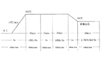
(試験条件)
・試料量:0.2g
・測定条件:図6に示す測定プログラムに従った。
・昇温還元測定:四重極質量分析計にてガス成分を検出した。
・検出フラグメント:m/z=2、18、28、44
・測定温度:400℃
・測定雰囲気:2.5体積%CO、H2O/He(室温にてバブリング導入)
・流量:100ml/min(Test conditions)
-Sample amount: 0.2g
Measurement conditions: According to the measurement program shown in FIG.
-Temperature reduction measurement: Gas components were detected with a quadrupole mass spectrometer.
Detection fragment: m / z = 2, 18, 28, 44
・ Measurement temperature: 400 ℃
Measurement atmosphere: 2.5% by volume CO, H 2 O / He (introducing bubbling at room temperature)
・ Flow rate: 100ml / min

表1より、参考例1−1は、比較例1−1〜比較例1−3より水素生成速度が速く、一酸化炭素シフト反応が効率良く進行していることが分かる。また、参考例1−1は、比較例1−1と比較例1−2とを足し合わせた以上の水素が生成した。 From Table 1, it can be seen that Reference Example 1-1 has a higher hydrogen production rate than Comparative Examples 1-1 to 1-3, and the carbon monoxide shift reaction proceeds efficiently. Further, in Reference Example 1-1, more hydrogen than the sum of Comparative Example 1-1 and Comparative Example 1-2 was generated.
(実施例1−1)
(1)ZrLaNd酸化物に所定量のロジウム(Rh)を含浸させた。次いで、乾燥させ、焼成して、Rh/ZrLaNd酸化物粉末を得た。次に、この粉末を固形分が40質量%となるように純水を投入し、粉砕して、第1の触媒ユニット含有スラリーを得た。
(2)また、ZrCeNd酸化物に鉄(Fe)が5質量%となるように所定量のLaSrFeO3を含浸させた。次いで、乾燥させ、焼成して、LaSrFeO3/ZrCeNd酸化物粉末を得た。次に、この粉末を固形分が40質量%となるように純水を投入し、粉砕して、第2の触媒ユニット含有スラリーを得た。
(3)上記(1)、(2)で得られたスラリーとベーマイトを所定量混合して混合スラリーを得た。次に、混合スラリーを乾燥し、550℃で3時間焼成して、第1の触媒ユニット及び第2の触媒ユニットを含有する粉末を得た。なお、本例の第1の触媒ユニットにおけるロジウム(Rh)担持濃度は、0.092質量%である。(Example 1-1)
(1) ZrLaNd oxide was impregnated with a predetermined amount of rhodium (Rh). Next, it was dried and fired to obtain an Rh / ZrLaNd oxide powder. Next, pure water was added to the powder so that the solid content was 40% by mass, and the powder was pulverized to obtain a first catalyst unit-containing slurry.
(2) A ZrCeNd oxide was impregnated with a predetermined amount of LaSrFeO 3 so that iron (Fe) was 5 mass%. Next, it was dried and fired to obtain a LaSrFeO 3 / ZrCeNd oxide powder. Next, this powder was charged with pure water so that the solid content was 40% by mass and pulverized to obtain a second catalyst unit-containing slurry.
(3) A predetermined amount of the slurry obtained in the above (1) and (2) and boehmite were mixed to obtain a mixed slurry. Next, the mixed slurry was dried and calcined at 550 ° C. for 3 hours to obtain a powder containing the first catalyst unit and the second catalyst unit. In addition, the rhodium (Rh) carrying | support density | concentration in the 1st catalyst unit of this example is 0.092 mass%.
(実施例1−2)
(1)ZrLaNd酸化物に所定量のロジウム(Rh)を含浸させた。次いで、乾燥させ、焼成して、Rh/ZrLaNd酸化物粉末を得た。次に、この粉末を固形分が40質量%となるように純水を投入し、粉砕して、第1の触媒ユニット含有スラリーを得た。
(2)また、ZrCeNd酸化物に鉄(Fe)が5質量%となるように所定量のLaSrFeO3を含浸させた。次いで、乾燥させ、焼成して、LaSrFeO3/ZrCeNd酸化物粉末を得た。次に、この粉末を固形分が40質量%となるように純水を投入し、粉砕して、第2の触媒ユニット含有スラリーを得た。
(3)上記(1)、(2)で得られたスラリーとベーマイトを所定量混合して混合スラリーを得た。次に、混合スラリーを乾燥し、550℃で3時間焼成して、表層粉末を得た。
(4)上記(3)で得られた粉末、バインダー、硝酸、純水を磁性ポットに投入し、アルミナボールと共に振とう粉砕して、表層スラリーを得た。
(5)アルミニウム酸化物(Al2O3)、バインダー、硝酸、純水を磁性ポットに投入し、アルミナボールと共に振とう粉砕して、内層スラリーを得た。
(6)上記(5)で得られた内層スラリーをセラミック製のハニカム担体に投入し、空気流にて余剰の内層スラリーを除去した。次いで、120℃で乾燥した。このときのコート量は、113g/Lである。
(7)上記(4)で得られた表層スラリーを上記(6)で得られた担体に投入し、空気流にて余剰の表層スラリーを除去した。次いで、120℃で乾燥した。しかる後、空気流通下、400℃で焼成して、本例の排ガス浄化用モノリス触媒を得た。このときのコート量は、124g/Lであった。また、排ガス浄化用モノリス触媒中のロジウム(Rh)量は0.03g/Lであった。(Example 1-2)
(1) ZrLaNd oxide was impregnated with a predetermined amount of rhodium (Rh). Next, it was dried and fired to obtain an Rh / ZrLaNd oxide powder. Next, pure water was added to the powder so that the solid content was 40% by mass, and the powder was pulverized to obtain a first catalyst unit-containing slurry.
(2) A ZrCeNd oxide was impregnated with a predetermined amount of LaSrFeO 3 so that iron (Fe) was 5 mass%. Next, it was dried and fired to obtain a LaSrFeO 3 / ZrCeNd oxide powder. Next, this powder was charged with pure water so that the solid content was 40% by mass and pulverized to obtain a second catalyst unit-containing slurry.
(3) A predetermined amount of the slurry obtained in the above (1) and (2) and boehmite were mixed to obtain a mixed slurry. Next, the mixed slurry was dried and fired at 550 ° C. for 3 hours to obtain a surface layer powder.
(4) The powder, binder, nitric acid, and pure water obtained in the above (3) were put into a magnetic pot, and shaken and pulverized with alumina balls to obtain a surface layer slurry.
(5) Aluminum oxide (Al 2 O 3 ), binder, nitric acid, and pure water were put into a magnetic pot and shaken and ground with alumina balls to obtain an inner layer slurry.
(6) The inner layer slurry obtained in the above (5) was put into a ceramic honeycomb carrier, and excess inner layer slurry was removed by an air flow. Subsequently, it dried at 120 degreeC. The coating amount at this time is 113 g / L.
(7) The surface layer slurry obtained in the above (4) was put into the carrier obtained in the above (6), and the excess surface layer slurry was removed by an air flow. Subsequently, it dried at 120 degreeC. Thereafter, it was calcined at 400 ° C. under air flow to obtain the monolith catalyst for exhaust gas purification of this example. The coating amount at this time was 124 g / L. Moreover, the rhodium (Rh) amount in the monolith catalyst for exhaust gas purification was 0.03 g / L.
(実施例1−3)
実施例1−2において、M2元素である鉄(Fe)をM2元素であるコバルト(Co)に変更したこと以外は、実施例1−2と同様の操作を繰り返して、本例の排ガス浄化用モノリス触媒を得た。(Example 1-3)
In Example 1-2, except that iron (Fe), which is an M2 element, is changed to cobalt (Co), which is an M2 element, the same operation as that in Example 1-2 is repeated, and this example is for exhaust gas purification. A monolith catalyst was obtained.
(実施例1−4)
実施例1−2において、M2元素である鉄(Fe)をM2元素であるマンガン(Mn)に変更したこと以外は、実施例1−2と同様の操作を繰り返して、本例の排ガス浄化用モノリス触媒を得た。(Example 1-4)
In Example 1-2, except that iron (Fe), which is an M2 element, is changed to manganese (Mn), which is an M2 element, the same operation as in Example 1-2 is repeated, and this example is for exhaust gas purification. A monolith catalyst was obtained.
(比較例2−1)
(1)ZrLaNd酸化物に所定量のロジウム(Rh)を含浸させた。次いで、乾燥させ、焼成して、Rh/ZrLaNd酸化物粉末を得た。次に、この粉末を固形分が40質量%となるように純水を投入し、粉砕して、第1の触媒ユニット含有スラリーを得た。
(2)また、ZrCeNd酸化物粉末を固形分が40質量%となるように純水を投入し、粉砕して、第2の触媒ユニット含有スラリーを得た。
(3)上記(1)、(2)で得られたスラリーとベーマイトを所定量混合して混合スラリーを得た。次に、混合スラリーを乾燥し、550℃で3時間焼成して、第1の触媒ユニット及び第2の触媒ユニットを含有する粉末を得た。なお、本例の第1の触媒ユニットにおけるロジウム(Rh)担持濃度は、0.092質量%である。(Comparative Example 2-1)
(1) ZrLaNd oxide was impregnated with a predetermined amount of rhodium (Rh). Next, it was dried and fired to obtain an Rh / ZrLaNd oxide powder. Next, pure water was added to the powder so that the solid content was 40% by mass, and the powder was pulverized to obtain a first catalyst unit-containing slurry.
(2) In addition, ZrCeNd oxide powder was charged with pure water so that the solid content was 40% by mass and pulverized to obtain a second catalyst unit-containing slurry.
(3) A predetermined amount of the slurry obtained in the above (1) and (2) and boehmite were mixed to obtain a mixed slurry. Next, the mixed slurry was dried and calcined at 550 ° C. for 3 hours to obtain a powder containing the first catalyst unit and the second catalyst unit. In addition, the rhodium (Rh) carrying | support density | concentration in the 1st catalyst unit of this example is 0.092 mass%.
(比較例2−2)
(1)ZrLaNd酸化物に所定量のロジウム(Rh)を含浸させた。次いで、乾燥させ、焼成して、Rh/ZrLaNd酸化物粉末を得た。次に、この粉末を固形分が40質量%となるように純水を投入し、粉砕して、第1の触媒ユニット含有スラリーを得た。
(2)また、ZrCeNd酸化物粉末を固形分が40質量%となるように純水を投入し、粉砕して、第2の触媒ユニット含有スラリーを得た。
(3)上記(1)、(2)で得られたスラリー、ベーマイトを所定量混合して混合スラリーを得た。次に、混合スラリーを乾燥し、550℃で3時間焼成して、表層粉末を得た。
バインダー、硝酸、純水を磁性ポットに投入し、アルミナボールと共に振とう粉砕して、表層スラリーを得た。
(4)上記(3)で得られた粉末、バインダー、硝酸、純水を磁性ポットに投入し、アルミナボールと共に振とう粉砕して、表層スラリーを得た。
(5)アルミニウム酸化物(Al2O3)、バインダー、硝酸、純水を磁性ポットに投入し、アルミナボールと共に振とう粉砕して、内層スラリーを得た。
(6)上記(5)で得られた内層スラリーをセラミック製のハニカム担体に投入し、空気流にて余剰の内層スラリーを除去した。次いで、120℃で乾燥した。このときのコート量は、113g/Lである。
(7)上記(4)で得られた表層スラリーを上記(6)で得られた担体に投入し、空気流にて余剰の表層スラリーを除去した。次いで、120℃で乾燥した。しかる後、空気流通下、400℃で焼成して、本例の排ガス浄化用モノリス触媒を得た。このときのコート量は、124g/Lであった。また、排ガス浄化用モノリス触媒中のロジウム(Rh)量は0.03g/Lであった。(Comparative Example 2-2)
(1) ZrLaNd oxide was impregnated with a predetermined amount of rhodium (Rh). Next, it was dried and fired to obtain an Rh / ZrLaNd oxide powder. Next, pure water was added to the powder so that the solid content was 40% by mass, and the powder was pulverized to obtain a first catalyst unit-containing slurry.
(2) In addition, ZrCeNd oxide powder was charged with pure water so that the solid content was 40% by mass and pulverized to obtain a second catalyst unit-containing slurry.
(3) A predetermined amount of the slurry and boehmite obtained in (1) and (2) above were mixed to obtain a mixed slurry. Next, the mixed slurry was dried and fired at 550 ° C. for 3 hours to obtain a surface layer powder.
Binder, nitric acid, and pure water were put into a magnetic pot and shaken and pulverized with alumina balls to obtain a surface layer slurry.
(4) The powder, binder, nitric acid, and pure water obtained in the above (3) were put into a magnetic pot, and shaken and pulverized with alumina balls to obtain a surface layer slurry.
(5) Aluminum oxide (Al 2 O 3 ), binder, nitric acid, and pure water were put into a magnetic pot and shaken and ground with alumina balls to obtain an inner layer slurry.
(6) The inner layer slurry obtained in the above (5) was put into a ceramic honeycomb carrier, and excess inner layer slurry was removed by an air flow. Subsequently, it dried at 120 degreeC. The coating amount at this time is 113 g / L.
(7) The surface layer slurry obtained in the above (4) was put into the carrier obtained in the above (6), and the excess surface layer slurry was removed by an air flow. Subsequently, it dried at 120 degreeC. Thereafter, it was calcined at 400 ° C. under air flow to obtain the monolith catalyst for exhaust gas purification of this example. The coating amount at this time was 124 g / L. Moreover, the rhodium (Rh) amount in the monolith catalyst for exhaust gas purification was 0.03 g / L.
(比較例2−3)
(1)ZrLaNd酸化物に所定量のロジウム(Rh)を含浸させた。次いで、乾燥させ、焼成して、Rh/ZrLaNd酸化物粉末を得た。次に、この粉末を固形分が40質量%となるように純水を投入し、粉砕して、第1の触媒ユニット含有スラリーを得た。
(2)また、ZrCe酸化物に鉄(Fe)が5質量%となるように所定量のFeO2を含浸させた。次いで、乾燥させ、焼成して、FeO2/ZrCe酸化物粉末を得た。次に、この粉末を固形分が40質量%となるように純水を投入し、粉砕して、第2の触媒ユニット含有スラリーを得た。
(3)上記(1)、(2)で得られたスラリーとベーマイトを所定量混合して混合スラリーを得た。次に、混合スラリーを乾燥し、550℃で3時間焼成して、表層粉末を得た。
(4)上記(3)で得られた粉末、バインダー、硝酸、純水を磁性ポットに投入し、アルミナボールと共に振とう粉砕して、表層スラリーを得た。
(5)アルミニウム酸化物(Al2O3)、バインダー、硝酸、純水を磁性ポットに投入し、アルミナボールと共に振とう粉砕して、内層スラリーを得た。
(6)上記(5)で得られた内層スラリーをセラミック製のハニカム担体に投入し、空気流にて余剰の内層スラリーを除去した。次いで、120℃で乾燥した。このときのコート量は、113g/Lである。
(7)上記(4)で得られた表層スラリーを上記(6)で得られた担体に投入し、空気流にて余剰の表層スラリーを除去した。次いで、120℃で乾燥した。しかる後、空気流通下、400℃で焼成して、本例の排ガス浄化用モノリス触媒を得た。このときのコート量は、124g/Lであった。また、排ガス浄化用モノリス触媒中のロジウム(Rh)量は0.03g/Lであった。
各例の仕様の一部を表2に示す。(Comparative Example 2-3)
(1) ZrLaNd oxide was impregnated with a predetermined amount of rhodium (Rh). Next, it was dried and fired to obtain an Rh / ZrLaNd oxide powder. Next, pure water was added to the powder so that the solid content was 40% by mass, and the powder was pulverized to obtain a first catalyst unit-containing slurry.
(2) Further, a predetermined amount of FeO 2 was impregnated in the ZrCe oxide so that iron (Fe) was 5 mass%. Next, it was dried and fired to obtain FeO 2 / ZrCe oxide powder. Next, this powder was charged with pure water so that the solid content was 40% by mass and pulverized to obtain a second catalyst unit-containing slurry.
(3) A predetermined amount of the slurry obtained in the above (1) and (2) and boehmite were mixed to obtain a mixed slurry. Next, the mixed slurry was dried and fired at 550 ° C. for 3 hours to obtain a surface layer powder.
(4) The powder, binder, nitric acid, and pure water obtained in the above (3) were put into a magnetic pot, and shaken and pulverized with alumina balls to obtain a surface layer slurry.
(5) Aluminum oxide (Al 2 O 3 ), binder, nitric acid, and pure water were put into a magnetic pot and shaken and ground with alumina balls to obtain an inner layer slurry.
(6) The inner layer slurry obtained in the above (5) was put into a ceramic honeycomb carrier, and excess inner layer slurry was removed by an air flow. Subsequently, it dried at 120 degreeC. The coating amount at this time is 113 g / L.
(7) The surface layer slurry obtained in the above (4) was put into the carrier obtained in the above (6), and the excess surface layer slurry was removed by an air flow. Subsequently, it dried at 120 degreeC. Thereafter, it was calcined at 400 ° C. under air flow to obtain the monolith catalyst for exhaust gas purification of this example. The coating amount at this time was 124 g / L. Moreover, the rhodium (Rh) amount in the monolith catalyst for exhaust gas purification was 0.03 g / L.
A part of the specification of each example is shown in Table 2.
[性能評価]
(水素生成性能試験)
上記実施例1−1及び比較例2−1の触媒(粉末)を用いて、下記条件下、一酸化炭素シフト反応試験を行った。得られた結果を表2に示す。[Performance evaluation]
(Hydrogen production performance test)
Using the catalyst (powder) of Example 1-1 and Comparative Example 2-1, a carbon monoxide shift reaction test was performed under the following conditions. The obtained results are shown in Table 2.
(試験条件)
・試料量:0.2g
・測定条件:図6に示す測定プログラムに従った。
・昇温還元測定:四重極質量分析計にてガス成分を検出した。
・検出フラグメント:m/z=2、18、28、44
・測定温度:400℃
・測定雰囲気:2.5体積%CO、H2O/He(室温にてバブリング導入)
・流量:100ml/min(Test conditions)
-Sample amount: 0.2g
Measurement conditions: According to the measurement program shown in FIG.
-Temperature reduction measurement: Gas components were detected with a quadrupole mass spectrometer.
Detection fragment: m / z = 2, 18, 28, 44
・ Measurement temperature: 400 ℃
Measurement atmosphere: 2.5% by volume CO, H 2 O / He (introducing bubbling at room temperature)
・ Flow rate: 100ml / min
(NOx排出量測定)
図7は、NOx排出量測定における触媒配置を示す説明図である。図7に示すように、排気量1.5Lの株式会社日産自動車製の車両のエンジン100の直下(マニホールド位置)に三元触媒2を配置し、その下流に下記条件で耐久させた実施例1−2〜実施例1−4、比較例2−2及び比較例2−3の排ガス浄化用モノリス触媒1を配置して、NEDCモード(コールドスタート)を走行し、このときの各例の排ガス浄化用モノリス触媒におけるNOx排出量を測定した。得られた結果を表2に示す。(NOx emission measurement)
FIG. 7 is an explanatory diagram showing the catalyst arrangement in the NOx emission measurement. As shown in FIG. 7, the three-
<耐久条件>
株式会社日産自動車製V型6気筒3.5Lエンジン後方に触媒を配置し、触媒入口温度が840℃となるよう調整し、排気ガス雰囲気下にて250時間耐久処理を行った。なお、使用燃料は無鉛ガソリンを使用した。<Durability conditions>
A catalyst was placed behind the Nissan Motor Co., Ltd. V-6 cylinder 3.5L engine, the catalyst inlet temperature was adjusted to 840 ° C., and 250 hours durability treatment was performed in an exhaust gas atmosphere. The fuel used was unleaded gasoline.
表2より、本発明の範囲に属する実施例1−1は、本発明外の比較例2−1より水素生成量が多く、一酸化炭素シフト反応が効率良く進行していることが分かる。
また、表2より、本発明の範囲に属する実施例1−2〜実施例1−4は、本発明外の比較例2−2及び比較例2−3と比較すると、NOx排出量が少ないことが分かる。From Table 2, it can be seen that Example 1-1 belonging to the scope of the present invention has a larger amount of hydrogen production than Comparative Example 2-1 outside the present invention, and the carbon monoxide shift reaction proceeds efficiently.
Further, from Table 2, Examples 1-2 to 1-4 belonging to the scope of the present invention have less NOx emission compared with Comparative Examples 2-2 and 2-3 outside the present invention. I understand.
(参考例2−1)
3質量%ランタン酸化物(La2O3)−5質量%ネオジム酸化物(Nd2O3)−ジルコニウム酸化物(ZrO2)(以下「ランタン酸化物(La2O3)−ネオジム酸化物(Nd2O3)−ジルコニウム酸化物(ZrO2)」を単に「ZrLaNd酸化物」ということがある。)に対して、ヘキサロジウム塩をインシピエントウェットネス法により含浸させた。次いで、150℃で12時間乾燥した。しかる後、400℃で1時間焼成して、本例の水素生成用触媒を得た。なお、本例の水素生成用触媒におけるロジウム(Rh)担持濃度は、0.092質量%である。(Reference Example 2-1)
3 mass% lanthanum oxide (La 2 O 3 ) -5 mass% neodymium oxide (Nd 2 O 3 ) -zirconium oxide (ZrO 2 ) (hereinafter referred to as “lanthanum oxide (La 2 O 3 ) -neodymium oxide ( Nd 2 O 3 ) -zirconium oxide (ZrO 2 ) ”may simply be referred to as“ ZrLaNd oxide ”), and was impregnated with a hexarhodium salt by an incipient wetness method. Subsequently, it dried at 150 degreeC for 12 hours. Thereafter, it was calcined at 400 ° C. for 1 hour to obtain a hydrogen generation catalyst of this example. The rhodium (Rh) loading concentration in the hydrogen generation catalyst of this example is 0.092% by mass.
(比較例3−1)
3質量%ランタン酸化物(La2O3)−ジルコニウム酸化物(ZrO2)(以下「ランタン酸化物(La2O3)−ジルコニウム酸化物(ZrO2)」を単に「ZrLa酸化物」ということがある。)に対して、ヘキサロジウム塩をインシピエントウェットネス法により含浸させた。次いで、150℃で12時間乾燥した。しかる後、400℃で1時間焼成して、本例の水素生成用触媒を得た。なお、本例の水素生成用触媒におけるロジウム(Rh)担持濃度は、0.092質量%である。(Comparative Example 3-1)
3 mass% lanthanum oxide (La 2 O 3 ) -zirconium oxide (ZrO 2 ) (hereinafter “lanthanum oxide (La 2 O 3 ) -zirconium oxide (ZrO 2 )” is simply referred to as “ZrLa oxide”. ) Was impregnated with an incipient wetness method. Subsequently, it dried at 150 degreeC for 12 hours. Thereafter, it was calcined at 400 ° C. for 1 hour to obtain a hydrogen generation catalyst of this example. The rhodium (Rh) loading concentration in the hydrogen generation catalyst of this example is 0.092% by mass.
(比較例3−2)
10質量%ランタン酸化物(La2O3)−アルミニウム酸化物(Al2O3)に対して、ヘキサロジウム塩をインシピエントウェットネス法により含浸させた。次いで、150℃で12時間乾燥した。しかる後、400℃で1時間焼成して、本例の水素生成用触媒を得た。なお、本例の水素生成用触媒におけるロジウム(Rh)担持濃度は、0.092質量%である。(Comparative Example 3-2)
Ten mass% lanthanum oxide (La 2 O 3 ) -aluminum oxide (Al 2 O 3 ) was impregnated with a hexarhodium salt by an incipient wetness method. Subsequently, it dried at 150 degreeC for 12 hours. Thereafter, it was calcined at 400 ° C. for 1 hour to obtain a hydrogen generation catalyst of this example. The rhodium (Rh) loading concentration in the hydrogen generation catalyst of this example is 0.092% by mass.
[性能評価]
(水素生成性能試験)
上記各例の水素生成用触媒(粉末)を用いて、下記条件下、水蒸気改質反応試験を行った。得られた結果を表3に示す。[Performance evaluation]
(Hydrogen production performance test)
Using the hydrogen generation catalyst (powder) in each of the above examples, a steam reforming reaction test was performed under the following conditions. The obtained results are shown in Table 3.
(試験条件)
・試料量:0.2g
・測定条件:図8に示す測定プログラムに従った。
・昇温還元測定:四重極質量分析計にてガス成分を検出した。
・検出フラグメント:m/z=2、18、28、42、44
・測定温度:400℃
・測定雰囲気:1体積%C3H6、7〜8体積%H2O/He
・流量:100ml/min(Test conditions)
-Sample amount: 0.2g
Measurement conditions: According to the measurement program shown in FIG.
-Temperature reduction measurement: Gas components were detected with a quadrupole mass spectrometer.
Detection fragment: m / z = 2, 18, 28, 42, 44
・ Measurement temperature: 400 ℃
Measurement Atmosphere: 1 vol% C 3 H 6, 7~8 vol% H 2 O / He
・ Flow rate: 100ml / min
表3より、参考例2−1は、比較例3−1及び比較例3−2より水素の濃度が高く、水蒸気改質反応が効率良く進行していることが分かる。 From Table 3, it can be seen that Reference Example 2-1 has a higher hydrogen concentration than Comparative Examples 3-1 and 3-2, and the steam reforming reaction proceeds efficiently.
(実施例2−1)
(1)まず、ZrLaNd酸化物に所定量のロジウム(Rh)を含浸させた。次いで、乾燥させ、焼成して、Rh/ZrLaNd酸化物粉末を得た。次に、この粉末を固形分が40質量%となるように純水を投入し、粉砕して、第1の触媒ユニット含有スラリーを得た。このスラリーを用いて、第1の触媒ユニット(水素生成用触媒)の平均二次粒子径を測定した。得られた結果は、表4に示す。
(2)また、ZrCeNd酸化物に鉄(Fe)が5質量%となるように所定量のLaSrFeO3を含浸させた。次いで、乾燥させ、焼成して、LaSrFeO3/ZrCeNd酸化物粉末を得た。次に、この粉末を固形分が40質量%となるように純水を投入し、粉砕して、第2の触媒ユニット含有スラリーを得た。
(3)上記(1)、(2)で得られたスラリーとベーマイトアルミナ、硝酸ランタン、硝酸を所定量混合して混合スラリーを得た。次に、混合スラリーを乾燥し、550℃で3時間焼成して、表層粉末を得た。
(4)上記(3)で得られた粉末、バインダー、硝酸、純水、造孔材を磁性ポットに投入し、アルミナボールと共に振とう粉砕して、表層スラリーを得た。このスラリーを用いて、排ガス浄化用触媒粉末の平均粒子径を測定した。得られた結果は、表4に示す。
(5)アルミニウム酸化物(Al2O3)、バインダー、硝酸、純水を磁性ポットに投入し、アルミナボールと共に振とう粉砕して、内層スラリーを得た。
(6)上記(5)で得られた内層スラリーをセラミック製のハニカム担体に投入し、空気流にて余剰の内層スラリーを除去した。次いで、120℃で乾燥した。このときのコート量は、113g/Lである。
(7)上記(4)で得られた表層スラリーを上記(6)で得られた担体に投入し、空気流にて余剰の表層スラリーを除去した。次いで、120℃で乾燥した。しかる後、空気流通下、400℃で焼成して、本例の排ガス浄化用モノリス触媒を得た。このときのコート量は、124g/Lであった。また、排ガス浄化用モノリス触媒中のロジウム(Rh)量は0.03g/Lであった。(Example 2-1)
(1) First, ZrLaNd oxide was impregnated with a predetermined amount of rhodium (Rh). Next, it was dried and fired to obtain an Rh / ZrLaNd oxide powder. Next, pure water was added to the powder so that the solid content was 40% by mass, and the powder was pulverized to obtain a first catalyst unit-containing slurry. Using this slurry, the average secondary particle diameter of the first catalyst unit (hydrogen generation catalyst) was measured. The results obtained are shown in Table 4.
(2) A ZrCeNd oxide was impregnated with a predetermined amount of LaSrFeO 3 so that iron (Fe) was 5 mass%. Next, it was dried and fired to obtain a LaSrFeO 3 / ZrCeNd oxide powder. Next, this powder was charged with pure water so that the solid content was 40% by mass and pulverized to obtain a second catalyst unit-containing slurry.
(3) A predetermined amount of the slurry obtained in (1) and (2) above and boehmite alumina, lanthanum nitrate, and nitric acid were mixed to obtain a mixed slurry. Next, the mixed slurry was dried and fired at 550 ° C. for 3 hours to obtain a surface layer powder.
(4) The powder, binder, nitric acid, pure water, and pore former obtained in the above (3) were put into a magnetic pot and shaken and ground together with alumina balls to obtain a surface layer slurry. Using this slurry, the average particle size of the exhaust gas-purifying catalyst powder was measured. The results obtained are shown in Table 4.
(5) Aluminum oxide (Al 2 O 3 ), binder, nitric acid, and pure water were put into a magnetic pot and shaken and ground with alumina balls to obtain an inner layer slurry.
(6) The inner layer slurry obtained in the above (5) was put into a ceramic honeycomb carrier, and excess inner layer slurry was removed by an air flow. Subsequently, it dried at 120 degreeC. The coating amount at this time is 113 g / L.
(7) The surface layer slurry obtained in the above (4) was put into the carrier obtained in the above (6), and the excess surface layer slurry was removed by an air flow. Subsequently, it dried at 120 degreeC. Thereafter, it was calcined at 400 ° C. under air flow to obtain the monolith catalyst for exhaust gas purification of this example. The coating amount at this time was 124 g / L. Moreover, the rhodium (Rh) amount in the monolith catalyst for exhaust gas purification was 0.03 g / L.
(実施例2−2)
実施例2−1において、M1元素であるストロンチウム(Sr)をM1元素であるバリウム(Ba)に変更したこと以外は、実施例2−1と同様の操作を繰り返して、本例の排ガス浄化用モノリス触媒を得た。(Example 2-2)
In Example 2-1, except that strontium (Sr), which is an M1 element, is changed to barium (Ba), which is an M1 element, the same operation as in Example 2-1 is repeated, and this example is for exhaust gas purification. A monolith catalyst was obtained.
(実施例2−3)
実施例2−1において、M1元素であるストロンチウム(Sr)をM1元素であるカルシウム(Ca)に変更したこと以外は、実施例2−1と同様の操作を繰り返して、本例の排ガス浄化用モノリス触媒を得た。(Example 2-3)
In Example 2-1, except that strontium (Sr), which is an M1 element, is changed to calcium (Ca), which is an M1 element, the same operation as that in Example 2-1 is repeated, and this example is for exhaust gas purification. A monolith catalyst was obtained.
(実施例2−4)
実施例2−1において、M2元素である鉄(Fe)をM2元素であるマンガン(Mn)に変更したこと以外は、実施例2−1と同様の操作を繰り返して、本例の排ガス浄化用モノリス触媒を得た。(Example 2-4)
In Example 2-1, the same operation as in Example 2-1 was repeated except that iron (Fe) as the M2 element was changed to manganese (Mn) as the M2 element. A monolith catalyst was obtained.
(実施例2−5)
実施例2−1において、M2元素である鉄(Fe)をM2元素であるコバルト(Co)に変更したこと以外は、実施例2−1と同様の操作を繰り返して、本例の排ガス浄化用モノリス触媒を得た。(Example 2-5)
In Example 2-1, the same operation as Example 2-1 was repeated except that iron (Fe), which is an M2 element, was changed to cobalt (Co), which was an M2 element. A monolith catalyst was obtained.
(実施例2−6)
実施例2−1において、ZrCeNd酸化物に鉄(Fe)が10質量%となるように所定量のLaSrFeO3を含浸させたこと以外は、実施例2−1と同様の操作を繰り返して、本例の排ガス浄化用モノリス触媒を得た。(Example 2-6)
In Example 2-1, the same operation as in Example 2-1 was repeated except that the ZrCeNd oxide was impregnated with a predetermined amount of LaSrFeO 3 so that iron (Fe) was 10% by mass. An example exhaust gas purification monolith catalyst was obtained.
(実施例2−7)
実施例2−1において、ZrCeNd酸化物に鉄(Fe)が15質量%となるように所定量のLaSrFeO3を含浸させたこと以外は、実施例2−1と同様の操作を繰り返して、本例の排ガス浄化用モノリス触媒を得た。(Example 2-7)
In Example 2-1, the same operation as in Example 2-1 was repeated except that the ZrCeNd oxide was impregnated with a predetermined amount of LaSrFeO 3 so that iron (Fe) was 15% by mass. An example exhaust gas purification monolith catalyst was obtained.
(実施例2−8)
実施例2−1において、表層スラリー調製時の造孔材の使用量を80質量%低減したこと以外は、実施例2−1と同様の操作を繰り返して、本例の排ガス浄化用モノリス触媒を得た。(Example 2-8)
In Example 2-1, the same operation as in Example 2-1 was repeated except that the amount of pore former used in the preparation of the surface layer slurry was reduced by 80% by mass. Obtained.
(実施例2−9)
実施例2−1において、ZrCeNd酸化物に鉄(Fe)が20質量%となるように所定量のLaSrFeO3を含浸させたこと以外は、実施例2−1と同様の操作を繰り返して、本例の排ガス浄化用モノリス触媒を得た。(Example 2-9)
In Example 2-1, the same operation as in Example 2-1 was repeated except that the ZrCeNd oxide was impregnated with a predetermined amount of LaSrFeO 3 so that iron (Fe) was 20% by mass. An example exhaust gas purification monolith catalyst was obtained.
(実施例2−10)
実施例2−1において、表層スラリー調製時の造孔材の使用量を100質量%低減したこと以外は、実施例2−1と同様の操作を繰り返して、本例の排ガス浄化用モノリス触媒を得た。(Example 2-10)
In Example 2-1, the same operation as in Example 2-1 was repeated except that the amount of pore former used in the preparation of the surface layer slurry was reduced by 100% by mass. Obtained.
(実施例2−11)
実施例2−1において、表層スラリー調製時の造孔材の使用量を20質量%増加したこと以外は、実施例2−1と同様の操作を繰り返して、本例の排ガス浄化用モノリス触媒を得た。(Example 2-11)
In Example 2-1, the same operation as in Example 2-1 was repeated except that the amount of pore former used in the preparation of the surface layer slurry was increased by 20% by mass. Obtained.
(実施例2−12)
実施例2−1において、第1の触媒ユニット含有スラリー調製時のRh/ZrLaNd酸化物粉末を純水に投入した後に粉砕する際の粉砕時間を半分にしたこと以外は、実施例2−1と同様の操作を繰り返して、本例の排ガス浄化用モノリス触媒を得た。(Example 2-12)
In Example 2-1, except that the pulverization time when pulverizing after putting the Rh / ZrLaNd oxide powder in preparing the first catalyst unit-containing slurry into pure water was halved, The same operation was repeated to obtain an exhaust gas purifying monolith catalyst of this example.
(実施例2−13)
実施例2−1において、表層スラリー調製時の表層粉末、バインダー、硝酸、純水、造孔材を磁性ポットに投入した後にアルミナボールと共に振とう粉砕する際の粉砕時間を半分にしたこと以外は、実施例2−1と同様の操作を繰り返して、本例の排ガス浄化用モノリス触媒を得た。(Example 2-13)
In Example 2-1, except that surface powder, binder, nitric acid, pure water, and pore former at the time of preparing the surface layer slurry were put into the magnetic pot and then the pulverization time when pulverizing with alumina balls was halved. The same operation as in Example 2-1 was repeated to obtain an exhaust gas purifying monolith catalyst of this example.
(実施例2−14)
実施例2−1において、表層スラリーのみをコーティングしたこと以外は、実施例2−1と同様の操作を繰り返して、本例の排ガス浄化用モノリス触媒を得た。(Example 2-14)
In Example 2-1, except that only the surface layer slurry was coated, the same operation as in Example 2-1 was repeated to obtain an exhaust gas purifying monolith catalyst of this example.
(比較例4−1)
(1)ZrLaNd酸化物に所定量のロジウム(Rh)を含浸させた。次いで、乾燥させ、焼成して、Rh/ZrLaNd酸化物粉末を得た。次に、この粉末を固形分が40質量%となるように純水を投入し、粉砕して、第1の触媒ユニット含有スラリーを得た。このスラリーを用いて、第1の触媒ユニット(水素生成用触媒)の平均二次粒子径を測定した。得られた結果は、表4に示す。
(2)また、ZrCeNd酸化物に鉄(Fe)が5質量%となるように所定量のLaSrFeO3を含浸させた。次いで、乾燥させ、焼成して、LaSrFeO3/ZrCeNd酸化物粉末を得た。次に、この粉末を固形分が40質量%となるように純水を投入し、粉砕して、第2の触媒ユニット含有スラリーを得た。
(3)上記(1)、(2)で得られたスラリー、バインダー、硝酸、純水、造孔材を磁性ポットに投入し、アルミナボールと共に振とう粉砕して、表層スラリーを得た。このスラリーを用いて、排ガス浄化用触媒粉末の平均粒子径を測定した。得られた結果は、表4に示す。
(4)アルミニウム酸化物(Al2O3)、バインダー、硝酸、純水を磁性ポットに投入し、アルミナボールと共に振とう粉砕して、内層スラリーを得た。
(5)上記(4)で得られた内層スラリーをセラミック製のハニカム担体に投入し、空気流にて余剰の内層スラリーを除去した。次いで、120℃で乾燥した。このときのコート量は、113g/Lである。
(6)上記(3)で得られた表層スラリーを上記(5)で得られた担体に投入し、空気流にて余剰の表層スラリーを除去した。次いで、120℃で乾燥した。しかる後、空気流通下、400℃で焼成して、本例の排ガス浄化用モノリス触媒を得た。このときのコート量は、124g/Lであった。また、排ガス浄化用モノリス触媒中のロジウム(Rh)量は0.03g/Lであった。(Comparative Example 4-1)
(1) ZrLaNd oxide was impregnated with a predetermined amount of rhodium (Rh). Next, it was dried and fired to obtain an Rh / ZrLaNd oxide powder. Next, pure water was added to the powder so that the solid content was 40% by mass, and the powder was pulverized to obtain a first catalyst unit-containing slurry. Using this slurry, the average secondary particle diameter of the first catalyst unit (hydrogen generation catalyst) was measured. The results obtained are shown in Table 4.
(2) A ZrCeNd oxide was impregnated with a predetermined amount of LaSrFeO 3 so that iron (Fe) was 5 mass%. Next, it was dried and fired to obtain a LaSrFeO 3 / ZrCeNd oxide powder. Next, this powder was charged with pure water so that the solid content was 40% by mass and pulverized to obtain a second catalyst unit-containing slurry.
(3) The slurry, binder, nitric acid, pure water, and pore former obtained in the above (1) and (2) were put into a magnetic pot and shaken and pulverized with alumina balls to obtain a surface layer slurry. Using this slurry, the average particle size of the exhaust gas-purifying catalyst powder was measured. The results obtained are shown in Table 4.
(4) Aluminum oxide (Al 2 O 3 ), binder, nitric acid, and pure water were put into a magnetic pot and shaken and ground with alumina balls to obtain an inner layer slurry.
(5) The inner layer slurry obtained in the above (4) was put into a ceramic honeycomb carrier, and excess inner layer slurry was removed by an air flow. Subsequently, it dried at 120 degreeC. The coating amount at this time is 113 g / L.
(6) The surface layer slurry obtained in the above (3) was put into the carrier obtained in the above (5), and the excess surface layer slurry was removed by an air flow. Subsequently, it dried at 120 degreeC. Thereafter, it was calcined at 400 ° C. under air flow to obtain the monolith catalyst for exhaust gas purification of this example. The coating amount at this time was 124 g / L. Moreover, the rhodium (Rh) amount in the monolith catalyst for exhaust gas purification was 0.03 g / L.
(比較例4−2)
(1)ZrLaNd酸化物に所定量のロジウム(Rh)を含浸させた。次いで、乾燥させ、焼成して、Rh/ZrLaNd酸化物粉末を得た。次に、この粉末を固形分が40質量%となるように純水を投入し、粉砕して、第1の触媒ユニット含有スラリーを得た。このスラリーを用いて、第1の触媒ユニット(水素生成用触媒)の平均二次粒子径を測定した。得られた結果は、表4に示す。
(2)ZrCeNd酸化物粉末を固形分が40質量%となるように純水を投入し、粉砕して、第2の触媒ユニット含有スラリーを得た。
(3)上記(1)、(2)で得られたスラリー、バインダー、硝酸、純水、造孔材を磁性ポットに投入し、アルミナボールと共に振とう粉砕して、表層スラリーを得た。このスラリーを用いて、排ガス浄化用触媒粉末の平均粒子径を測定した。得られた結果は、表4に示示す。
(4)アルミニウム酸化物(Al2O3)、バインダー、硝酸、純水を磁性ポットに投入し、アルミナボールと共に振とう粉砕し、内層スラリーを得た。
(5)上記(4)で得られた内層スラリーをセラミック製のハニカム担体に投入し、空気流にて余剰の内層スラリーを除去した。次いで、120℃で乾燥した。このときのコート量は113g/Lである。
(6)上記(3)で得られた表層スラリーを上記(5)で得られた担体に投入し、空気流にて余剰の表層スラリーを除去した。次いで、120℃で乾燥した。しかる後、空気流通下、400℃で焼成して、本例の排ガス浄化用モノリス触媒を得た。このときのコート量は、124g/Lであった。また、排ガス浄化用モノリス触媒中のロジウム(Rh)量は0.03g/Lであった。
各例の仕様を表4に示す。なお、細孔容量測定は、排ガス浄化用触媒をハニカム担体にコートした触媒の一部を用い、水銀圧入法により細孔容量を測定した。また、第1の触媒ユニット(水素生成用触媒)の平均二次粒子径及び排ガス浄化用触媒粉末の平均粒子径の測定には、株式会社堀場製作所製レーザ回折/散乱式粒度分布測定装置LA−920を用いた。更に、表中の数値は測定時のD50の値を示した。(Comparative Example 4-2)
(1) ZrLaNd oxide was impregnated with a predetermined amount of rhodium (Rh). Next, it was dried and fired to obtain an Rh / ZrLaNd oxide powder. Next, pure water was added to the powder so that the solid content was 40% by mass, and the powder was pulverized to obtain a first catalyst unit-containing slurry. Using this slurry, the average secondary particle diameter of the first catalyst unit (hydrogen generation catalyst) was measured. The results obtained are shown in Table 4.
(2) Pure water was added to the ZrCeNd oxide powder so that the solid content was 40% by mass and pulverized to obtain a second catalyst unit-containing slurry.
(3) The slurry, binder, nitric acid, pure water, and pore former obtained in the above (1) and (2) were put into a magnetic pot and shaken and pulverized with alumina balls to obtain a surface layer slurry. Using this slurry, the average particle size of the exhaust gas-purifying catalyst powder was measured. The results obtained are shown in Table 4.
(4) Aluminum oxide (Al 2 O 3 ), binder, nitric acid, and pure water were put into a magnetic pot and shaken and ground with alumina balls to obtain an inner layer slurry.
(5) The inner layer slurry obtained in the above (4) was put into a ceramic honeycomb carrier, and excess inner layer slurry was removed by an air flow. Subsequently, it dried at 120 degreeC. The coating amount at this time is 113 g / L.
(6) The surface layer slurry obtained in the above (3) was put into the carrier obtained in the above (5), and the excess surface layer slurry was removed by an air flow. Subsequently, it dried at 120 degreeC. Thereafter, it was calcined at 400 ° C. under air flow to obtain the monolith catalyst for exhaust gas purification of this example. The coating amount at this time was 124 g / L. Moreover, the rhodium (Rh) amount in the monolith catalyst for exhaust gas purification was 0.03 g / L.
Table 4 shows the specifications of each example. The pore volume was measured by mercury porosimetry using a part of the catalyst obtained by coating the honeycomb carrier with the exhaust gas purification catalyst. For the measurement of the average secondary particle diameter of the first catalyst unit (hydrogen generation catalyst) and the average particle diameter of the exhaust gas purification catalyst powder, a laser diffraction / scattering particle size distribution measuring apparatus LA- manufactured by HORIBA, Ltd. 920 was used. Furthermore, the numerical value in a table | surface showed the value of D50 at the time of a measurement.
[性能評価]
(HC排出量測定)
図7は、HC排出量測定における触媒配置を示す説明図である。図7に示すように、排気量1.5Lの株式会社日産自動車製の車両のエンジン100の直下(マニホールド位置)に三元触媒2を配置し、その下流に下記条件で耐久させた各例の排ガス浄化用モノリス触媒1を配置して、NEDCモード(コールドスタート)を走行し、このときの各例の排ガス浄化用モノリス触媒におけるHC排出量を測定した。得られた結果を表4に示す。[Performance evaluation]
(Measurement of HC emissions)
FIG. 7 is an explanatory view showing a catalyst arrangement in the HC emission amount measurement. As shown in FIG. 7, the three-
<耐久条件>
株式会社日産自動車製V型6気筒3.5Lエンジン後方に触媒を配置し、触媒入口温度が840℃となるよう調整し、排気ガス雰囲気下にて250時間耐久処理を行った。なお、使用燃料は無鉛ガソリンを使用した。<Durability conditions>
A catalyst was placed behind the Nissan Motor Co., Ltd. V-6 cylinder 3.5L engine, the catalyst inlet temperature was adjusted to 840 ° C., and 250 hours durability treatment was performed in an exhaust gas atmosphere. The fuel used was unleaded gasoline.
表4より、本発明の範囲に属する実施例2−1〜実施例2−5及び実施例2−9は、本発明外の比較例4−1及び比較例4−2と比較すると、HC排出量が少ないことが分かる。
また、表4より、本発明の範囲に属する実施例2−1、実施例2−6、実施例2−7及び実施例2−9を比較すると、M2元素の含有量が15質量%以下である実施例2−1、実施例2−6及び実施例2−7において、HC排出量が少ないことが分かる。
更に、表4より、本発明の範囲に属する実施例2−1、実施例2−10及び実施例2−11を比較すると、0.1〜1μmの細孔径を有する細孔の細孔容量が0.03〜0.07cm3/gである実施例2−1において、HC排出量が少ないことが分かる。
また、表4より、本発明の範囲に属する実施例2−1及び実施例2−12を比較すると、水素生成触媒の平均二次粒子径が300nm以下である実施例2−1において、HC排出量が少ないことが分かる。
更に、表4より、本発明の範囲に属する実施例2−1及び実施例2−13を比較すると、排ガス浄化用触媒の平均粒子径が6μm以下である実施例2−1において、HC排出量が少ないことが分かる。
更にまた、表4より、本発明の範囲に属する実施例2−1及び実施例2−14を比較すると、アンダーコート層を有する実施例2−1において、HC排出量が少ないことが分かる。From Table 4, Example 2-1 to Example 2-5 and Example 2-9 belonging to the scope of the present invention are compared with Comparative Example 4-1 and Comparative Example 4-2 outside the present invention, compared with HC emission. You can see that the amount is small.
From Table 4, when Example 2-1, Example 2-6, Example 2-7 and Example 2-9 belonging to the scope of the present invention are compared, the content of M2 element is 15% by mass or less. In certain Example 2-1, Example 2-6, and Example 2-7, it can be seen that the amount of HC emission is small.
Further, from Table 4, when Example 2-1, Example 2-10 and Example 2-11 belonging to the scope of the present invention are compared, the pore volume of pores having a pore diameter of 0.1 to 1 μm is shown. In Example 2-1 which is 0.03-0.07 cm < 3 > / g, it turns out that there is little HC discharge | emission amount.
Further, from Table 4, when Example 2-1 and Example 2-12 belonging to the scope of the present invention are compared, in Example 2-1 in which the average secondary particle diameter of the hydrogen generation catalyst is 300 nm or less, HC emission You can see that the amount is small.
Further, from Table 4, when Example 2-1 and Example 2-13 belonging to the scope of the present invention are compared, in Example 2-1, in which the average particle diameter of the exhaust gas purifying catalyst is 6 μm or less, the HC emission amount It can be seen that there are few.
Furthermore, Table 4 shows that when Example 2-1 and Example 2-14 that belong to the scope of the present invention are compared, Example 2-1 having an undercoat layer has a small amount of HC emission.
(実施例3−1)
参考例2−1で得られた水素生成用触媒を用いたこと以外は、実施例2−1と同様の操作を繰り返して、本例の排ガス浄化用モノリス触媒を得た。(Example 3-1)
Except for using the hydrogen generation catalyst obtained in Reference Example 2-1, the same operation as in Example 2-1 was repeated to obtain an exhaust gas purifying monolith catalyst of this example.
(比較例5−1)
比較例3−1で得られた水素生成用触媒を用いたこと以外は、実施例2−1と同様の操作を繰り返して、本例の排ガス浄化用モノリス触媒を得た。(Comparative Example 5-1)
Except for using the hydrogen production catalyst obtained in Comparative Example 3-1, the same operation as in Example 2-1 was repeated to obtain an exhaust gas purifying monolith catalyst of this example.
[性能評価]
(排ガス浄化性能試験)
図7に示すように、排気量1.5Lの株式会社日産自動車製の車両のエンジン100の直下(マニホールド位置)に三元触媒2を配置し、その下流に下記条件で耐久させた各例の排ガス浄化用モノリス触媒1を配置して、NEDCモード(コールドスタート)を走行し、このときの各例の排ガス浄化用モノリス触媒におけるHC転化率、CO転化率及びNOx転化率を計測した。なお、触媒入口温度は350℃である。得られた結果を図9に示す。[Performance evaluation]
(Exhaust gas purification performance test)
As shown in FIG. 7, the three-
<耐久条件>
株式会社日産自動車製V型6気筒3.5Lエンジン後方に触媒を配置し、触媒入口温度が840℃となるよう調整し、排気ガス雰囲気下にて250時間耐久処理を行った。なお、使用燃料は無鉛ガソリンを使用した。<Durability conditions>
A catalyst was placed behind the Nissan Motor Co., Ltd. V-6 cylinder 3.5L engine, the catalyst inlet temperature was adjusted to 840 ° C., and 250 hours durability treatment was performed in an exhaust gas atmosphere. The fuel used was unleaded gasoline.
図9より、本発明の範囲に属する実施例3−1は、本発明外の比較例5−1と比較すると、転化率が8%程度向上することが分かる。 From FIG. 9, it can be seen that the conversion rate of Example 3-1 belonging to the scope of the present invention is improved by about 8% as compared with Comparative Example 5-1 outside the present invention.
以上、本発明を若干の実施形態及び実施例によって説明したが、本発明はこれらに限定されるものではなく、本発明の要旨の範囲内で種々の変形が可能である。 As mentioned above, although this invention was demonstrated with some embodiment and an Example, this invention is not limited to these, A various deformation | transformation is possible within the range of the summary of this invention.
例えば、上述した各実施形態や各実施例の排ガス浄化用触媒及び排ガス浄化用モノリス触媒に記載した構成は、各実施形態や各実施例に限定されるものではなく、例えば、各実施形態や各実施例の構成を上述した各実施形態や各実施例以外の組み合わせにしたり、構成の細部を変更したりすることができる。 For example, the configurations described in the exhaust gas purification catalyst and the exhaust gas purification monolith catalyst of each embodiment and each example described above are not limited to each embodiment or each example. For example, each embodiment and each example The configurations of the examples can be combined with the embodiments and the examples other than those described above, or the details of the configurations can be changed.
1 排ガス浄化用モノリス触媒
2 三元触媒
10 触媒層
11 排ガス浄化用触媒
12 第1の触媒ユニット(水素生成触媒)
12a 貴金属
12b 酸化物
14 第2の触媒ユニット
14a 酸素吸蔵放出材
14b ペロブスカイト型酸化物
16 保持材
20 アンダーコート層
30 モノリス担体
30a 排ガス流路
100 エンジンDESCRIPTION OF
12a noble
Claims (13)
酸素吸蔵放出材、及び該酸素吸蔵放出材と接触して配設されるペロブスカイト型酸化物からなる第2の触媒ユニットと、
上記第1の触媒ユニットと上記第2の触媒ユニットとを隔てた状態で保持する保持材と、を含有し、
上記水素生成触媒が、貴金属と該貴金属を担持する酸化物とからなり、該酸化物が、ランタンと、ジルコニウムと、ネオジム、サマリウム、ユウロピウム、マグネシウム及びカルシウムからなる群より選ばれる少なくとも1種の添加元素とを含み、
上記ペロブスカイト型酸化物が、一般式(1)
LaxM11−xM2O3−δ・・・(1)
(式(1)中、Laはランタン、M1はバリウム(Ba)、ストロンチウム(Sr)及びカルシウム(Ca)からなる群より選ばれる少なくとも1種、M2は鉄(Fe)、コバルト(Co)及びマンガン(Mn)からなる群より選ばれる少なくとも1種を示し、xは0<x≦1、δは0≦δ≦1を満足する。)で表される
ことを特徴とする排ガス浄化用触媒。 A first catalyst unit comprising a hydrogen production catalyst;
A second catalyst unit comprising an oxygen storage / release material and a perovskite oxide disposed in contact with the oxygen storage / release material;
A holding material that holds the first catalyst unit and the second catalyst unit in a separated state,
The hydrogen generation catalyst comprises a noble metal and an oxide supporting the noble metal, and the oxide is at least one addition selected from the group consisting of lanthanum, zirconium, neodymium, samarium, europium, magnesium and calcium. Elements and
The perovskite oxide has the general formula (1)
La x M1 1-x M2O 3-δ (1)
(In formula (1), La is lanthanum, M1 is at least one selected from the group consisting of barium (Ba), strontium (Sr) and calcium (Ca), M2 is iron (Fe), cobalt (Co) and manganese) (Mn) represents at least one selected from the group consisting of x, x satisfies 0 <x ≦ 1, and δ satisfies 0 ≦ δ ≦ 1).
酸素吸蔵放出材、及び該酸素吸蔵放出材に接触して配設されるペロブスカイト型酸化物からなる第2の触媒ユニットと、
上記第1の触媒ユニットと上記第2の触媒ユニットとを隔てた状態で保持する保持材と、を含有し、
上記水素生成触媒が、貴金属と該貴金属を担持する複合酸化物とからなり、該複合酸化物が、ランタンと、ジルコニウムと、ネオジム、サマリウム、ユウロピウム、マグネシウム及びカルシウムからなる群より選ばれる少なくとも1種の添加元素とを含み、
上記ペロブスカイト型酸化物が、一般式(1)
LaxM11−xM2O3−δ・・・(1)
(式(1)中、Laはランタン、M1はバリウム(Ba)、ストロンチウム(Sr)及びカルシウム(Ca)からなる群より選ばれる少なくとも1種、M2は鉄(Fe)、コバルト(Co)及びマンガン(Mn)からなる群より選ばれる少なくとも1種を示し、xは0<x≦1、δは0≦δ≦1を満足する。)で表される
ことを特徴とする排ガス浄化用触媒。 A first catalyst unit comprising a hydrogen production catalyst;
A second catalyst unit comprising an oxygen storage / release material and a perovskite oxide disposed in contact with the oxygen storage / release material;
A holding material that holds the first catalyst unit and the second catalyst unit in a separated state,
The hydrogen generation catalyst comprises a noble metal and a complex oxide supporting the noble metal, and the complex oxide is at least one selected from the group consisting of lanthanum, zirconium, neodymium, samarium, europium, magnesium and calcium. And an additive element of
The perovskite oxide has the general formula (1)
La x M1 1-x M2O 3-δ (1)
(In formula (1), La is lanthanum, M1 is at least one selected from the group consisting of barium (Ba), strontium (Sr) and calcium (Ca), M2 is iron (Fe), cobalt (Co) and manganese) (Mn) represents at least one selected from the group consisting of x, x satisfies 0 <x ≦ 1, and δ satisfies 0 ≦ δ ≦ 1).
上記添加元素が、ネオジムである
ことを特徴とする請求項1、2、4のいずれか1つの項に記載の排ガス浄化用触媒。 The noble metal is rhodium,
The exhaust gas-purifying catalyst according to any one of claims 1, 2 , and 4 , wherein the additive element is neodymium.
Applications Claiming Priority (5)
| Application Number | Priority Date | Filing Date | Title |
|---|---|---|---|
| PCT/JP2014/062666 WO2015173880A1 (en) | 2014-05-13 | 2014-05-13 | Hydrogen-generating catalyst, and exhaust gas purification catalyst |
| JPPCT/JP2014/062667 | 2014-05-13 | ||
| JPPCT/JP2014/062666 | 2014-05-13 | ||
| PCT/JP2014/062667 WO2015173881A1 (en) | 2014-05-13 | 2014-05-13 | Hydrogen-generating catalyst, and exhaust gas purification catalyst |
| PCT/JP2015/051126 WO2015174102A1 (en) | 2014-05-13 | 2015-01-16 | Exhaust gas purification catalyst |
Publications (2)
| Publication Number | Publication Date |
|---|---|
| JPWO2015174102A1 JPWO2015174102A1 (en) | 2017-04-20 |
| JP6362040B2 true JP6362040B2 (en) | 2018-07-25 |
Family
ID=54479649
Family Applications (1)
| Application Number | Title | Priority Date | Filing Date |
|---|---|---|---|
| JP2016519127A Active JP6362040B2 (en) | 2014-05-13 | 2015-01-16 | Exhaust gas purification catalyst |
Country Status (5)
| Country | Link |
|---|---|
| US (1) | US9878308B2 (en) |
| EP (1) | EP3144062B1 (en) |
| JP (1) | JP6362040B2 (en) |
| CN (1) | CN106457226B (en) |
| WO (1) | WO2015174102A1 (en) |
Families Citing this family (3)
| Publication number | Priority date | Publication date | Assignee | Title |
|---|---|---|---|---|
| US10946362B1 (en) * | 2017-02-24 | 2021-03-16 | University Of South Florida | Perovskite oxides for thermochemical conversion of carbon dioxide |
| CN110676472A (en) * | 2019-09-30 | 2020-01-10 | 潍柴动力股份有限公司 | Fuel pretreatment catalyst for solid oxide fuel cell system and preparation method thereof |
| CN113244926A (en) * | 2020-09-14 | 2021-08-13 | 昆明理工大学 | Perovskite catalyst for synergistically catalyzing and oxidizing nitric oxide and mercury and preparation method thereof |
Family Cites Families (18)
| Publication number | Priority date | Publication date | Assignee | Title |
|---|---|---|---|---|
| JP2000027625A (en) * | 1998-07-09 | 2000-01-25 | Honda Motor Co Ltd | Exhaust emission control device for internal combustion engine |
| JP2002542015A (en) * | 1999-04-19 | 2002-12-10 | エンゲルハード・コーポレーシヨン | Catalyst composition comprising ceria and platinum group metal |
| US6881384B1 (en) * | 1999-08-30 | 2005-04-19 | Daihatsu Motor Co., Ltd. | Catalytic converter for cleaning exhaust gas |
| JP3688947B2 (en) * | 1999-09-03 | 2005-08-31 | ダイハツ工業株式会社 | Exhaust gas purification catalyst |
| JP3715211B2 (en) * | 2000-09-07 | 2005-11-09 | 本田技研工業株式会社 | Exhaust gas purification device for internal combustion engine |
| JP2002126522A (en) | 2000-10-20 | 2002-05-08 | Mitsubishi Heavy Ind Ltd | Hydrocarbon reforming catalyst |
| JP4764609B2 (en) * | 2004-03-15 | 2011-09-07 | 独立行政法人産業技術総合研究所 | Nitrogen oxide removal catalyst |
| JP4830624B2 (en) * | 2006-05-15 | 2011-12-07 | マツダ株式会社 | Exhaust gas purification catalyst |
| JP4328338B2 (en) * | 2006-06-01 | 2009-09-09 | ダイハツ工業株式会社 | Catalyst for exhaust gas purification of internal combustion engine |
| EP2308595B1 (en) * | 2008-07-04 | 2019-04-17 | Nissan Motor Co., Ltd. | Exhaust gas purifying catalyst |
| WO2010013574A1 (en) * | 2008-07-31 | 2010-02-04 | 日産自動車株式会社 | Catalyst for purification of exhaust gas |
| JP2010051886A (en) * | 2008-08-27 | 2010-03-11 | Mazda Motor Corp | Catalyst for cleaning exhaust gas |
| CN102137718B (en) * | 2008-09-02 | 2015-09-16 | 日产自动车株式会社 | Exhaust gas purification catalyst and manufacture method thereof |
| MY152352A (en) * | 2009-03-04 | 2014-09-15 | Nissan Motor | Exhaust gas purifying catalyst and method for manufacturing the same |
| US8409518B2 (en) * | 2009-03-16 | 2013-04-02 | GM Global Technology Operations LLC | Sulfur tolerant perovskite supported catalysts |
| JP5041103B2 (en) * | 2009-11-17 | 2012-10-03 | 日産自動車株式会社 | Exhaust gas purification catalyst and method for producing the same |
| US9101914B2 (en) * | 2011-03-31 | 2015-08-11 | Nissan Motor Co., Ltd. | Exhaust gas purifying catalyst, exhaust gas purifying monolith catalyst, and method for manufacturing exhaust gas purifying catalyst |
| EP2893979B1 (en) * | 2012-09-10 | 2020-11-25 | Nissan Motor Co., Ltd | Exhaust gas purification catalyst, exhaust gas purification monolith catalyst, and method for producing exhaust gas purification catalyst |
-
2015
- 2015-01-16 US US15/309,930 patent/US9878308B2/en active Active
- 2015-01-16 JP JP2016519127A patent/JP6362040B2/en active Active
- 2015-01-16 CN CN201580025179.9A patent/CN106457226B/en active Active
- 2015-01-16 WO PCT/JP2015/051126 patent/WO2015174102A1/en active Application Filing
- 2015-01-16 EP EP15792201.4A patent/EP3144062B1/en active Active
Also Published As
| Publication number | Publication date |
|---|---|
| US9878308B2 (en) | 2018-01-30 |
| CN106457226B (en) | 2021-05-11 |
| EP3144062B1 (en) | 2020-08-05 |
| EP3144062A4 (en) | 2017-07-19 |
| JPWO2015174102A1 (en) | 2017-04-20 |
| CN106457226A (en) | 2017-02-22 |
| US20170266644A1 (en) | 2017-09-21 |
| WO2015174102A1 (en) | 2015-11-19 |
| EP3144062A1 (en) | 2017-03-22 |
Similar Documents
| Publication | Publication Date | Title |
|---|---|---|
| JP4956801B2 (en) | Exhaust gas purification catalyst and method for producing the same | |
| KR102275358B1 (en) | Oxidation catalyst for internal combustion engine exhaust gas treatment | |
| JP4648089B2 (en) | Exhaust gas purification catalyst | |
| JP2013536756A (en) | Catalyst for lean-burn gasoline engines with improved NO oxidation activity | |
| JPWO2008093471A1 (en) | Catalyst system used in automobile exhaust gas purification device, exhaust gas purification device using the same, and exhaust gas purification method | |
| JP5589321B2 (en) | Exhaust gas purification catalyst and method for producing the same | |
| JP2009107901A (en) | Inorganic mixed oxide and exhaust gas purification catalyst using the same | |
| JP6362040B2 (en) | Exhaust gas purification catalyst | |
| CN113042045A (en) | Catalyst for exhaust gas purification | |
| JP5777690B2 (en) | Exhaust gas purification catalyst and method for producing the same | |
| JP2008018418A (en) | Catalyst for cleaning exhaust gas | |
| JP4573993B2 (en) | Exhaust gas purification catalyst and method for producing the same | |
| WO2015173880A1 (en) | Hydrogen-generating catalyst, and exhaust gas purification catalyst | |
| WO2013132895A1 (en) | Oxidation catalyst and exhaust gas purification method using same | |
| JP4794834B2 (en) | Exhaust gas purification catalyst | |
| CN102266773A (en) | Exhaust gas purification catalyst | |
| WO2015173881A1 (en) | Hydrogen-generating catalyst, and exhaust gas purification catalyst | |
| JP6096818B2 (en) | Exhaust gas purification catalyst, method for producing the same, and exhaust gas purification method using the same | |
| JP5831083B2 (en) | Exhaust gas purification catalyst and method for producing the same | |
| JP7448620B2 (en) | Nitrogen oxide storage materials and exhaust gas purification catalysts | |
| JP4822049B2 (en) | Exhaust gas purification catalyst and exhaust gas purification method using the same | |
| JP2017141151A (en) | Complex oxide and evaluation method of oxygen storage capacity | |
| JP2017180453A (en) | Exhaust emission control device and its process of manufacture | |
| JP2017023999A (en) | Catalyst for exhaust purification | |
| JP3885339B2 (en) | Exhaust gas purification catalyst, method for producing the same, and method for using the same |
Legal Events
| Date | Code | Title | Description |
|---|---|---|---|
| A621 | Written request for application examination |
Free format text: JAPANESE INTERMEDIATE CODE: A621 Effective date: 20161027 |
|
| A131 | Notification of reasons for refusal |
Free format text: JAPANESE INTERMEDIATE CODE: A131 Effective date: 20171016 |
|
| A521 | Request for written amendment filed |
Free format text: JAPANESE INTERMEDIATE CODE: A523 Effective date: 20171213 |
|
| A131 | Notification of reasons for refusal |
Free format text: JAPANESE INTERMEDIATE CODE: A131 Effective date: 20180118 |
|
| A521 | Request for written amendment filed |
Free format text: JAPANESE INTERMEDIATE CODE: A523 Effective date: 20180305 |
|
| TRDD | Decision of grant or rejection written | ||
| A01 | Written decision to grant a patent or to grant a registration (utility model) |
Free format text: JAPANESE INTERMEDIATE CODE: A01 Effective date: 20180604 |
|
| R151 | Written notification of patent or utility model registration |
Ref document number: 6362040 Country of ref document: JP Free format text: JAPANESE INTERMEDIATE CODE: R151 |
|
| A61 | First payment of annual fees (during grant procedure) |
Free format text: JAPANESE INTERMEDIATE CODE: A61 Effective date: 20180617 |