WO2012133498A1 - タール除去装置 - Google Patents
タール除去装置 Download PDFInfo
- Publication number
- WO2012133498A1 WO2012133498A1 PCT/JP2012/058079 JP2012058079W WO2012133498A1 WO 2012133498 A1 WO2012133498 A1 WO 2012133498A1 JP 2012058079 W JP2012058079 W JP 2012058079W WO 2012133498 A1 WO2012133498 A1 WO 2012133498A1
- Authority
- WO
- WIPO (PCT)
- Prior art keywords
- tar
- combustion
- zone
- injection
- separation
- Prior art date
- Legal status (The legal status is an assumption and is not a legal conclusion. Google has not performed a legal analysis and makes no representation as to the accuracy of the status listed.)
- Ceased
Links
Images




Classifications
-
- B—PERFORMING OPERATIONS; TRANSPORTING
- B01—PHYSICAL OR CHEMICAL PROCESSES OR APPARATUS IN GENERAL
- B01D—SEPARATION
- B01D49/00—Separating dispersed particles from gases, air or vapours by other methods
-
- C—CHEMISTRY; METALLURGY
- C10—PETROLEUM, GAS OR COKE INDUSTRIES; TECHNICAL GASES CONTAINING CARBON MONOXIDE; FUELS; LUBRICANTS; PEAT
- C10J—PRODUCTION OF PRODUCER GAS, WATER-GAS, SYNTHESIS GAS FROM SOLID CARBONACEOUS MATERIAL, OR MIXTURES CONTAINING THESE GASES; CARBURETTING AIR OR OTHER GASES
- C10J3/00—Production of combustible gases containing carbon monoxide from solid carbonaceous fuels
- C10J3/46—Gasification of granular or pulverulent flues in suspension
- C10J3/48—Apparatus; Plants
- C10J3/482—Gasifiers with stationary fluidised bed
-
- C—CHEMISTRY; METALLURGY
- C10—PETROLEUM, GAS OR COKE INDUSTRIES; TECHNICAL GASES CONTAINING CARBON MONOXIDE; FUELS; LUBRICANTS; PEAT
- C10J—PRODUCTION OF PRODUCER GAS, WATER-GAS, SYNTHESIS GAS FROM SOLID CARBONACEOUS MATERIAL, OR MIXTURES CONTAINING THESE GASES; CARBURETTING AIR OR OTHER GASES
- C10J3/00—Production of combustible gases containing carbon monoxide from solid carbonaceous fuels
- C10J3/46—Gasification of granular or pulverulent flues in suspension
- C10J3/54—Gasification of granular or pulverulent fuels by the Winkler technique, i.e. by fluidisation
- C10J3/56—Apparatus; Plants
-
- C—CHEMISTRY; METALLURGY
- C10—PETROLEUM, GAS OR COKE INDUSTRIES; TECHNICAL GASES CONTAINING CARBON MONOXIDE; FUELS; LUBRICANTS; PEAT
- C10K—PURIFYING OR MODIFYING THE CHEMICAL COMPOSITION OF COMBUSTIBLE GASES CONTAINING CARBON MONOXIDE
- C10K1/00—Purifying combustible gases containing carbon monoxide
- C10K1/20—Purifying combustible gases containing carbon monoxide by treating with solids; Regenerating spent purifying masses
- C10K1/26—Regeneration of the purifying material contains also apparatus for the regeneration of the purifying material
-
- C—CHEMISTRY; METALLURGY
- C10—PETROLEUM, GAS OR COKE INDUSTRIES; TECHNICAL GASES CONTAINING CARBON MONOXIDE; FUELS; LUBRICANTS; PEAT
- C10K—PURIFYING OR MODIFYING THE CHEMICAL COMPOSITION OF COMBUSTIBLE GASES CONTAINING CARBON MONOXIDE
- C10K1/00—Purifying combustible gases containing carbon monoxide
- C10K1/20—Purifying combustible gases containing carbon monoxide by treating with solids; Regenerating spent purifying masses
- C10K1/30—Purifying combustible gases containing carbon monoxide by treating with solids; Regenerating spent purifying masses with moving purifying masses
-
- C—CHEMISTRY; METALLURGY
- C10—PETROLEUM, GAS OR COKE INDUSTRIES; TECHNICAL GASES CONTAINING CARBON MONOXIDE; FUELS; LUBRICANTS; PEAT
- C10K—PURIFYING OR MODIFYING THE CHEMICAL COMPOSITION OF COMBUSTIBLE GASES CONTAINING CARBON MONOXIDE
- C10K3/00—Modifying the chemical composition of combustible gases containing carbon monoxide to produce an improved fuel, e.g. one of different calorific value, which may be free from carbon monoxide
- C10K3/001—Modifying the chemical composition of combustible gases containing carbon monoxide to produce an improved fuel, e.g. one of different calorific value, which may be free from carbon monoxide by thermal treatment
- C10K3/003—Reducing the tar content
-
- F—MECHANICAL ENGINEERING; LIGHTING; HEATING; WEAPONS; BLASTING
- F23—COMBUSTION APPARATUS; COMBUSTION PROCESSES
- F23C—METHODS OR APPARATUS FOR COMBUSTION USING FLUID FUEL OR SOLID FUEL SUSPENDED IN A CARRIER GAS OR AIR
- F23C10/00—Fluidised bed combustion apparatus
- F23C10/002—Fluidised bed combustion apparatus for pulverulent solid fuel
-
- F—MECHANICAL ENGINEERING; LIGHTING; HEATING; WEAPONS; BLASTING
- F23—COMBUSTION APPARATUS; COMBUSTION PROCESSES
- F23C—METHODS OR APPARATUS FOR COMBUSTION USING FLUID FUEL OR SOLID FUEL SUSPENDED IN A CARRIER GAS OR AIR
- F23C10/00—Fluidised bed combustion apparatus
- F23C10/02—Fluidised bed combustion apparatus with means specially adapted for achieving or promoting a circulating movement of particles within the bed or for a recirculation of particles entrained from the bed
- F23C10/04—Fluidised bed combustion apparatus with means specially adapted for achieving or promoting a circulating movement of particles within the bed or for a recirculation of particles entrained from the bed the particles being circulated to a section, e.g. a heat-exchange section or a return duct, at least partially shielded from the combustion zone, before being reintroduced into the combustion zone
- F23C10/08—Fluidised bed combustion apparatus with means specially adapted for achieving or promoting a circulating movement of particles within the bed or for a recirculation of particles entrained from the bed the particles being circulated to a section, e.g. a heat-exchange section or a return duct, at least partially shielded from the combustion zone, before being reintroduced into the combustion zone characterised by the arrangement of separation apparatus, e.g. cyclones, for separating particles from the flue gases
- F23C10/10—Fluidised bed combustion apparatus with means specially adapted for achieving or promoting a circulating movement of particles within the bed or for a recirculation of particles entrained from the bed the particles being circulated to a section, e.g. a heat-exchange section or a return duct, at least partially shielded from the combustion zone, before being reintroduced into the combustion zone characterised by the arrangement of separation apparatus, e.g. cyclones, for separating particles from the flue gases the separation apparatus being located outside the combustion chamber
-
- C—CHEMISTRY; METALLURGY
- C10—PETROLEUM, GAS OR COKE INDUSTRIES; TECHNICAL GASES CONTAINING CARBON MONOXIDE; FUELS; LUBRICANTS; PEAT
- C10J—PRODUCTION OF PRODUCER GAS, WATER-GAS, SYNTHESIS GAS FROM SOLID CARBONACEOUS MATERIAL, OR MIXTURES CONTAINING THESE GASES; CARBURETTING AIR OR OTHER GASES
- C10J2300/00—Details of gasification processes
- C10J2300/09—Details of the feed, e.g. feeding of spent catalyst, inert gas or halogens
- C10J2300/0913—Carbonaceous raw material
- C10J2300/093—Coal
-
- C—CHEMISTRY; METALLURGY
- C10—PETROLEUM, GAS OR COKE INDUSTRIES; TECHNICAL GASES CONTAINING CARBON MONOXIDE; FUELS; LUBRICANTS; PEAT
- C10J—PRODUCTION OF PRODUCER GAS, WATER-GAS, SYNTHESIS GAS FROM SOLID CARBONACEOUS MATERIAL, OR MIXTURES CONTAINING THESE GASES; CARBURETTING AIR OR OTHER GASES
- C10J2300/00—Details of gasification processes
- C10J2300/09—Details of the feed, e.g. feeding of spent catalyst, inert gas or halogens
- C10J2300/0953—Gasifying agents
- C10J2300/0973—Water
- C10J2300/0976—Water as steam
-
- C—CHEMISTRY; METALLURGY
- C10—PETROLEUM, GAS OR COKE INDUSTRIES; TECHNICAL GASES CONTAINING CARBON MONOXIDE; FUELS; LUBRICANTS; PEAT
- C10J—PRODUCTION OF PRODUCER GAS, WATER-GAS, SYNTHESIS GAS FROM SOLID CARBONACEOUS MATERIAL, OR MIXTURES CONTAINING THESE GASES; CARBURETTING AIR OR OTHER GASES
- C10J2300/00—Details of gasification processes
- C10J2300/09—Details of the feed, e.g. feeding of spent catalyst, inert gas or halogens
- C10J2300/0983—Additives
- C10J2300/0993—Inert particles, e.g. as heat exchange medium in a fluidized or moving bed, heat carriers, sand
-
- C—CHEMISTRY; METALLURGY
- C10—PETROLEUM, GAS OR COKE INDUSTRIES; TECHNICAL GASES CONTAINING CARBON MONOXIDE; FUELS; LUBRICANTS; PEAT
- C10J—PRODUCTION OF PRODUCER GAS, WATER-GAS, SYNTHESIS GAS FROM SOLID CARBONACEOUS MATERIAL, OR MIXTURES CONTAINING THESE GASES; CARBURETTING AIR OR OTHER GASES
- C10J2300/00—Details of gasification processes
- C10J2300/16—Integration of gasification processes with another plant or parts within the plant
- C10J2300/1625—Integration of gasification processes with another plant or parts within the plant with solids treatment
- C10J2300/1637—Char combustion
-
- C—CHEMISTRY; METALLURGY
- C10—PETROLEUM, GAS OR COKE INDUSTRIES; TECHNICAL GASES CONTAINING CARBON MONOXIDE; FUELS; LUBRICANTS; PEAT
- C10J—PRODUCTION OF PRODUCER GAS, WATER-GAS, SYNTHESIS GAS FROM SOLID CARBONACEOUS MATERIAL, OR MIXTURES CONTAINING THESE GASES; CARBURETTING AIR OR OTHER GASES
- C10J2300/00—Details of gasification processes
- C10J2300/18—Details of the gasification process, e.g. loops, autothermal operation
- C10J2300/1807—Recycle loops, e.g. gas, solids, heating medium, water
-
- C—CHEMISTRY; METALLURGY
- C10—PETROLEUM, GAS OR COKE INDUSTRIES; TECHNICAL GASES CONTAINING CARBON MONOXIDE; FUELS; LUBRICANTS; PEAT
- C10J—PRODUCTION OF PRODUCER GAS, WATER-GAS, SYNTHESIS GAS FROM SOLID CARBONACEOUS MATERIAL, OR MIXTURES CONTAINING THESE GASES; CARBURETTING AIR OR OTHER GASES
- C10J2300/00—Details of gasification processes
- C10J2300/18—Details of the gasification process, e.g. loops, autothermal operation
- C10J2300/1853—Steam reforming, i.e. injection of steam only
Definitions
- the present invention relates to a tar removal device for removing a tar content contained in a gasification gas generated in a gasification furnace.
- This application claims priority based on Japanese Patent Application No. 2011-69742 for which it applied to Japan on March 28, 2011, and uses the content here.
- Gasification systems are known that use solid fuel such as coal, residues generated during oil refining, waste plastic, or organic waste such as sludge, municipal waste, and biomass fuel as gasification raw materials.
- a gasification gas is generated by supplying it to a gasification furnace such as a steam gasification furnace, a pyrolysis gasification furnace or a partial oxidation gasification furnace, and purifying the gasification gas.
- the purified gas obtained by purification is supplied as fuel for power generation facilities, combustion furnaces, internal combustion engines, etc., or as raw material gas for hydrogen production equipment, ammonia production equipment, etc.
- tar tar-like component
- This tar adheres to piping and thermal equipment provided in the latter stage of the gasification furnace, and causes problems such as lowering the function of the thermal equipment or stopping the function due to blockage.
- Patent Document 1 discloses that a container body in which a predetermined layer is filled with a ceramic layer made of an assembly of a large number of porous ceramic heat storage bodies that capture tar in gasified gas, and a gasified gas in the ceramic layer of the partition. And a switching means for selectively circulating the gasifying agent, and trapping tar by passing gasification gas through the ceramic layer, and then passing the gasifying agent through the ceramic layer trapping tar. It is described that the gasifying agent containing the removed tar is removed and fed to the gasifier.
- This invention is made in view of the said conventional problem, and provides the tar removal apparatus which can remove effectively the tar content contained in the gasification gas produced
- the gasification of a two-column gasifier having a combustion furnace for heating a heat medium and a gasification furnace for gasifying a raw material by taking in the heat medium heated in the combustion furnace.
- a tar removal device that removes tar contained in gasification gas generated in a furnace, and injects gasification gas from the gasification furnace and fluidizes the circulation particles to circulate the tar in the gasification gas.
- the tar separation device and the tar combustion device have fluidized injection nozzles at the bottom and are provided on the left and right in the container body,
- the tar separation device and the tar combustion device are partitioned by left and right partition walls that extend forward and backward in the center of their opposing positions to form a front and rear passage between the container body and tar separation of one of the front and rear passages.
- On the apparatus side there is a separation-side low injection zone for injecting the gasified gas with an injection amount lower than the set injection amount of the separation-side fluidization zone formed by uniform injection of the gasification gas by the fluidization injection nozzle.
- the tar separation device side of the other front and rear passages has a separation side high injection zone for injecting gasified gas at an injection amount higher than the set injection amount of the separation side fluidization zone,
- a combustion side high injection zone for injecting air at a higher injection amount than the set injection amount of the combustion side fluidization zone formed by uniform injection of air by the fluidization injection nozzle is provided on the tar combustion device side of the one passage.
- a combustion side low injection zone for injecting air at an injection amount lower than the set injection amount of the combustion side fluidization zone is provided on the tar combustion device side of the other passages before and after.
- the tar separation device is used instead of the left and right partition walls that are positioned at the front and rear centers of the opposed positions and form the front and rear passages. And a front and rear partition walls extending left and right to form front and rear passages at positions facing the tar combustion apparatus.
- the injection nozzle of the separation-side low injection zone is relative to the fluidization injection nozzle provided in the separation-side fluidization zone.
- the flow passage cross-sectional area is set small, and the injection nozzle provided in the separation-side high injection zone has a flow passage cross-sectional area set larger than the fluidization injection nozzle provided in the separation-side fluidization zone, and the combustion-side high injection
- the injection nozzle of the zone has a larger flow cross-sectional area than the fluidization injection nozzle provided in the combustion side fluidization zone, and the injection nozzle of the combustion side low injection zone is fluidized injection provided in the combustion side fluidization zone.
- the channel cross-sectional area is set small with respect to the nozzle.
- a fluidizing spray nozzle having a uniform flow path cross-sectional area is provided at the bottom of the tar separation device, and
- the tar combustion device is provided with a fluidization injection nozzle having a uniform flow path cross-sectional area at the bottom, and the tar separation device has an intermediate pressure introduction chamber for introducing gasification gas to the separation side fluidization zone, and a separation side A low-pressure introduction chamber for introducing the gasification gas to the low injection zone, and a high-pressure introduction chamber for introducing the gasification gas to the separation-side high injection zone, and supplying the intermediate-pressure introduction chamber, the low-pressure introduction chamber, and the high-pressure introduction chamber
- the tar combustion device comprises a pressure adjusting means for adjusting the pressure of the gasified gas, wherein the tar combustion device has an intermediate pressure introduction chamber for introducing air to the combustion side fluidization zone, a high pressure introduction chamber for introducing air to the combustion side high injection zone, and a combustion
- the gasified gas is ejected by the fluidizing injection nozzle provided at the bottom to fluidize the circulating particles and the tar of the gasified gas.
- a separation device that introduces a fluid derived from the separation device and separates it into circulating particles and gasified gas to which tar adheres, and a circulation that supplies the circulating particles to which the tar separated by the separation device adheres to the tar combustion device
- a separation device that separates the path, the circulating particles introduced from the tar combustion device into the circulating particles and the combustion exhaust gas, and the circulating particles separated by the separation device And a circulation path for supplying to the tar separator.
- the tar content contained in the gasification gas generated in the gasification furnace can be effectively removed with a simple device configuration. Furthermore, since the heat of the combustion gas in which tar is combusted can be effectively used for heating circulating particles in the combustion furnace, the thermal efficiency is increased and the gasification rate is improved.
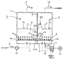
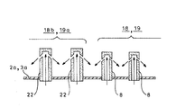
- FIG. 2A It is a side view which shows schematic structure of the two-column type gasifier provided with the tar removal apparatus of this invention. It is a front view which shows the outline of 1st Embodiment of the tar removal apparatus of this invention. It is a top view of FIG. 2A. It is a front view which shows the modification of the tar removal apparatus shown to FIG. 2A. It is a top view of FIG. 3A. It is sectional drawing which shows an example of the injection nozzle with which the tar removal apparatus shown to FIG. 2A and 3A is equipped. It is sectional drawing which shows the other example of the injection nozzle with which the tar removal apparatus shown to FIG. 2A and 3A is equipped.
- FIG. 1 shows a schematic configuration of a two-column gasifier equipped with a tar removing apparatus of the present invention
- 43 is a combustion furnace in which a heat medium A made of particles such as sand is charged.
- Coal and other fuels 44 are supplied from the lower side of the combustion furnace 43, and fluid combustion of the fuel 44 is performed by the air 45 supplied from below to heat the heat medium A.
- the combustion fluid taken out from the upper part of the combustion furnace 43 is guided to a solid-gas separation device 46 such as a cyclone and separated into exhaust gas E and heat medium A, and the heat medium A is supplied to the gasification furnace 47.
- the gasification furnace 47 is supplied with a raw material 48 such as coal, fluidized by a gasifying agent 49 such as water vapor supplied to the gasification furnace 47 from below, and taking in the heat of the heat medium A.
- the raw material is gasified (endothermic reaction).
- the heat medium A the temperature of which has been lowered by the supply of heat in the gasification furnace 47, is returned to the combustion furnace 43 and circulated for use.
- the gasification gas 9 generated in the gasification furnace 47 is supplied from below to the tar separation device 2 constituting the tar removal device of the present invention.
- the tar separation device 2 contains circulating particles B made of alumina, porous particles, etc., and the gasified gas 9 is supplied from below to fluidize the circulating particles B. During this flow, the tar in the gasified gas 9 comes into contact with the circulating particles B and adheres (adsorbs) to the circulating particles B. Accordingly, the gasification gas 9 from which tar has been removed is taken out from the tar separation device 2.
- 3 is a tar combustion device that constitutes a tar removal device.
- the tar combustion device 3 takes in the circulating particles B to which tar is attached in the tar separation device 2 and burns the tar with air 15 supplied from below.
- . 17 is a heat exchanger for exchanging heat with the exhaust gas E separated by the solid-gas separation device 46 from the air fan 14. By introducing the air 15 heated by the heat exchanger 17 into the tar combustion device 3, tar To burn.
- the circulating particles B burned with tar in the tar combustion device 3 are circulated to the tar separation device 2.
- the combustion gas 16 obtained by burning the tar in the tar combustion device 3 is supplied to the combustion furnace 43 as a combustion gas.
- the tar combustion device 3 is supplied with air 15 that is larger than the amount of air necessary for burning tar, so that sufficient oxygen is contained in the combustion gas 16. include. Therefore, by supplying the combustion gas 16 containing oxygen and heated by combustion of tar to the combustion furnace 43 in this way, the combustion temperature of the combustion furnace 43 can be raised. You can save.
- the gasification rate in the gasification furnace 47 can be increased by increasing the temperature of the heat medium A.
- the combustion gas 16 may be supplied alone to the combustion furnace 43, or may be supplied to the combustion furnace 43 together with the air 45.
- This tar removal device includes a tar separation device 2 and a tar combustion device 3 on the left and right sides of the container body 1, and a front and rear (an opposite position) between the opposite tar separation device 2 and the tar combustion device 3 (see FIG. 2B, left and right partition walls 6 are formed in the middle of the upper and lower sides in 2B and extending forward and backward to form the front and rear passages 4 and 5 between them.
- An injection nozzle 8 that communicates with the introduction chamber 7 provided at the lower portion of the tar separation device 2 is provided at the bottom 2a.
- the gasified gas 9 generated in the gasification furnace is pressurized by the pressurized fan 10 and introduced into the introduction chamber 7, and the gasified gas 9 is ejected from the fluidizing injection nozzle 8, thereby causing sand, alumina, and porous particles inside.
- the fluidized bed 11 is formed by fluidizing the circulating particles B made of materials. In the fluidized bed 11, when the gasified gas 9 comes into contact with the circulating particles B, the tar in the gasified gas 9 is removed by adhering (adsorbing) to the circulating particles B. At this time, the circulating particles B are gasified. Heated by the gas 9.
- the gasified gas 9 from which tar has been removed by the circulating particles B in the tar separator 2 is led out from the upper part of the tar separator 2.
- the gasified gas 9 is introduced into the introduction chamber 7 via the pressurized fan 10, but when the gasified gas 9 has a pressure necessary for fluidizing the circulating particles B, The pressure fan 10 can be omitted.
- a number of fluidized spray nozzles 8 communicating with the introduction chamber 12 provided at the bottom of the tar combustion device 3 are provided at the bottom 3a.
- the pressurized air 15 from the air fan 14 is supplied to the introduction chamber 12, and the air circulating particles B are fluidized by ejecting the air 15 from the fluidizing nozzle 8 to form a fluidized bed 11 '.
- the circulating particles B to which the tar is attached come into contact with the air 15 so that the tar is burned and the temperature of the circulating particles B is increased.
- Combustion gas 16 obtained by burning tar in the tar combustion device 3 is led out from the upper portion of the tar combustion device 3.
- the fuel 13 may be supplied to the tar combustion device 3.
- the gasification gas 9 is sprayed by the fluidization nozzle 8 as a set injection amount (an injection amount and / or an injection speed necessary for obtaining a predetermined fluidized bed 11 height).
- the fluidized bed 11 is formed by uniformly injecting the force with an “injection amount”), and the separation-side fluidization zone 18 for separating tar is formed.
- the fluidized injection nozzle 8 uniformly injects the air 15 with the set injection amount to form the fluidized bed 11 ′, and the combustion side fluidization zone 19 for burning the tar. Is forming.
- the set injection amount by the fluidizing injection nozzle 8 is set so that the heights of the fluidized bed 11 and the fluidized bed 11 ′ are equal.
- the gasified gas 9 is injected to the tar separation device 2 side in one of the passages 4 and 5 provided at the front and rear with an injection amount lower than the set injection amount of the gasification gas 9 by the separation side fluidization zone 18.
- a separation-side low injection zone 18a is formed.
- a separation side high injection zone 18b for injecting the gasified gas 9 with an injection amount higher than the set injection amount of the gasified gas 9 by the separation side fluidization zone 18. Is formed.
- a combustion side high injection zone 19a for injecting air 15 with an injection amount higher than the set injection amount of air 15 by the combustion side fluidization zone 19 is formed on the tar combustion device 3 side in one passage 4.
- a combustion side low injection zone 19b for injecting air 15 with an injection amount lower than the set injection amount of air 15 by the combustion side fluidization zone 19 is formed on the tar combustion device 3 side in the other passage 5. .
- the tar separation device 2 and the tar combustion device 3 may be configured with the same volume, but the tar separation device 2 requires a required residence time for effectively attaching tar to the circulating particles B and separating them. On the other hand, since the tar combustion apparatus 3 can burn and lose tar in a relatively short time, the volume of the tar combustion apparatus 3 can be made smaller than that of the tar separation apparatus 2.
- FIGS. 3A and 3B show a modification of the embodiment of FIGS. 2A and 2B.
- the front and rear passages 4, 5 extend forward and backward to the center of the opposed position and between the container body 1.
- the front and rear passages 4 and 5 are formed so as to form the front and rear passages 4 and 5 between the container body 1 and the left and right partition walls 6 formed in the center.
- the case where the partition wall 20 is provided is shown.
- Other configurations are the same as those in FIGS. 2A and 2B.
- FIG. 4A shows a specific configuration example for setting the injection amount.
- the separation-side low injection zone 18a and the combustion-side low injection zone 19b are separated from the separation-side fluidization zone 18 and the combustion-side fluidization zone.
- a low injection nozzle 21 having a small channel cross-sectional area is provided with respect to the fluidization injection nozzle 8 provided at 19. As shown in FIG. 4A, the low injection nozzle 21 may be one in which the fluidization injection nozzle 8 is downsized.
- the flow path is cut off with respect to the fluidization injection nozzles 8 provided in the separation side fluidization zone 18 and the combustion side fluidization zone 19 in the separation side high injection zone 18b and the combustion side high injection zone 19a.
- a high injection nozzle 22 having a large area is provided.
- the high spray nozzle 22 may be a fluidized spray nozzle 8 having a large size.
- the gasified gas 9 generated in the gasification furnace is pressurized by a pressure fan 10 and introduced into the introduction chamber 7 of the tar separation device 2.
- the circulating particles B are fluidized to form the fluidized bed 11.
- the pressurized air 15 from the air fan 14 is supplied to the introduction chamber 12 of the tar combustion device 3 and ejected from the fluidizing injection nozzle 8 to fluidize the circulating particles B to form a fluidized bed 11 ′.
- the set injection amount by the fluidization injection nozzle 8 is set to be equal so that the heights of the fluidized bed 11 and the fluidized bed 11 ′ are equal.
- the separation side low injection zone 18a by the low injection nozzle 21 is formed on the tar separation device 2 side of the one passage 4, the circulating particles B to which the tar adheres in the separation side fluidization zone 18 has a small jetting force. It moves so as to fall toward the separation side low injection zone 18a and the passage 4 side.
- the combustion side high injection zone 19a by the high injection nozzle 22 is formed on the tar combustion device 3 side of one passage 4, the circulating particles B that have fallen to the passage 4 side are combusted as described above. It is effectively blown up by the side high injection zone 19 a and led to the combustion side fluidization zone 19. Then, while flowing in the fluidized bed 11 of the combustion side fluidizing zone 19, it is burned by air and becomes combustion exhaust gas, which is discharged from the upper portion of the tar combustion device 3.
- the combustion side low injection zone 19b by the low injection nozzle 21 is formed on the tar combustion device 3 side of the other passage 5, the circulating particles B in which the tar is combusted in the combustion side fluidization zone 19 are formed. Moves so as to drop toward the combustion side low injection zone 19b and the passage 5 side with a small jetting force.
- the separation side high injection zone 18b by the high injection nozzle 22 is formed on the tar separation device 2 side of the other passage 5, the circulating particles B falling to the passage 5 side are separated as described above. The air is effectively blown up by the side high injection zone 18 b and led to the separation side fluidization zone 18.
- the circulating particles B in the separation side fluidization zone 18 are separated from the separation side low injection zone 18a ⁇ passage 4 ⁇ combustion side high injection zone 19a ⁇ combustion side fluidization zone 19 ⁇ combustion side low injection zone 19b ⁇ passage 5.
- the separation side high injection zone 18b ⁇ the separation side fluidization zone 18 is circulated, whereby the tar in the gasification gas 9 can be effectively removed continuously.
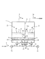
- FIG. 5 is a front view schematically showing a second embodiment of the tar removing device of the present invention.
- the differences from the first embodiment shown in FIG. 2 are the bottom 2a of the tar separating device 2, and the tar.
- the point is that the bottom 3a of the combustion apparatus 3 is provided with a fluidizing injection nozzle 8 having a uniform flow path cross-sectional area.
- the tar separation device 2 includes an intermediate pressure introduction chamber 23 for introducing the gasification gas 9 to the separation side fluidization zone 18, a low pressure introduction chamber 24 for introducing the gasification gas 9 to the separation side low injection zone 18a, and a separation side high A high-pressure introduction chamber 25 for introducing the gasification gas 9 to the injection zone 18b (see FIG. 2B), and the pressure of the gasification gas 9 supplied to the medium-pressure introduction chamber 23, the low-pressure introduction chamber 24, and the high-pressure introduction chamber 25 Pressure adjusting means for adjusting is provided.
- FIG. 2B Pressure adjusting means for adjusting
- the high-pressure gasified gas 9 from the pressurized fan 10 is introduced as it is to the high-pressure introduction chamber 25, and the pressure is supplied to the intermediate-pressure introduction chamber 23 by the first damper 26 (pressure adjusting means).
- the medium pressure gasified gas 9 is adjusted.
- the low-pressure gasification gas 9 whose pressure is adjusted to be lower than that of the medium-pressure introduction chamber 23 is led to the low-pressure introduction chamber 24 by the second damper 27 (pressure adjusting means).
- the tar combustion device 3 includes an intermediate pressure introduction chamber 28 for introducing the air 15 to the combustion side fluidization zone 19, a high pressure introduction chamber 29 for introducing the air 15 to the combustion side high injection zone 19a, and a combustion side low injection zone 19b ( 2), and a pressure adjusting means for adjusting the pressure of the air supplied to the intermediate pressure introducing chamber 28, the high pressure introducing chamber 29, and the low pressure introducing chamber 30.
- the high-pressure air 15 from the air fan 14 is directly guided to the high-pressure introduction chamber 29, and the pressure is adjusted by the first damper 31 (pressure adjusting means) to the medium-pressure introduction chamber 2.
- the medium pressure air 15 is guided.
- the low pressure air 15 whose pressure is adjusted to be lower than that of the medium pressure introduction chamber 28 is guided to the low pressure introduction chamber 30 by the second damper 32 (pressure adjusting means).
- the tar separation device 2 includes the intermediate pressure introduction chambers 23 and 28, the low pressure introduction chambers 24 and 30, and the high pressure introduction chambers 25 and 29 that are set by the pressure adjusting means. Even if the tar combustion apparatus 3 includes the fluidizing injection nozzle 8 having a uniform flow path cross-sectional area, the separation-side fluidization zone 18, the separation-side low-injection zone 18a, and the separation are separated as in the example shown in FIGS. 2A and 2B. A side high injection zone 18b, a combustion side fluidization zone 19, a combustion side high injection zone 19a, and a combustion side low injection zone 9b are formed. As a result, as shown by an arrow X in FIG. 2B, the circulating particles B circulate in the tar separation device 2 and the tar combustion device 3, and the tar in the gasification gas 9 can be removed effectively continuously. It becomes.
- FIG. 6 is a front view schematically showing a third embodiment of the tar removing apparatus of the present invention similar to FIG.
- another additional pressurizing fan 34 is provided in the flow path 33 branched upstream of the pressurizing fan 10, and the high-pressure gasification gas 9 from the additional pressurizing fan 34 is directly supplied to the high-pressure introduction chamber 25.
- the medium pressure gasified gas 9 from the pressure fan 10 is directly guided to the medium pressure introduction chamber 23.
- the low-pressure gasification gas 9 whose pressure is adjusted to be lower than that of the medium-pressure introduction chamber 23 is led to the low-pressure introduction chamber 24 by the second damper 35 (pressure adjusting means).
- an additional air fan 36 different from the air fan 14 is provided, and the high-pressure air 15 from the additional air fan 36 is directly guided to the high-pressure introduction chamber 29, and the medium-pressure air 15 from the air fan 14 is directly supplied. It leads to the medium pressure introduction chamber 28. Further, the low-pressure air 15 whose pressure is adjusted to be lower than that of the medium-pressure introduction chamber 28 is guided to the low-pressure introduction chamber 30 by the first damper 37 (pressure adjusting means).
- gasification in which the pressure is set by providing an original pressure fan for the medium pressure introducing chamber 23, the low pressure introducing chamber 24, and the high pressure introducing chamber 25 of the tar separation device 2 in the embodiment of FIG. Even if the gas 9 is supplied, or the air 15 having a pressure set by the original pressure fan is supplied to the medium pressure introduction chamber 28, the high pressure introduction chamber 29 and the low pressure introduction chamber 30 of the tar combustion device 3. Good.
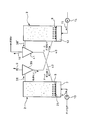
- FIG. 7 is a front view showing an outline of the fourth embodiment of the tar removing apparatus of the present invention.
- the gasified gas 9 supplied from the pressurized fan 10 to the introduction chamber 7 is ejected by the fluidizing spray nozzle 8 provided in the bottom portion 2 a to fluidize the circulating particles B and to gasify the gas 9.
- the tar separation device 2 that attaches the tar to the circulating particles B and the fluid 15 that is supplied from the air fan 14 to the introduction chamber 12 are ejected by the fluidizing spray nozzle 8 provided in the bottom 3a to fluidize the circulating particles B.
- the fluidization injection nozzle 8 provided in the tar separation device 2 and the fluidization injection nozzle 8 provided in the tar combustion device 3 have a larger ejection amount than the fluidization injection nozzle 8 shown in FIG. 2A to FIG.
- the gasified gas 9 and the air 15 are jetted out.
- separator 38 which introduce
- a circulation path 42 for supplying the circulating particles B from which the tar separated by the separation device 41 has been removed to the tar separation device 2.
- the circulating medium to which tar has adhered in the tar separation device 2 is circulated and supplied to the tar combustion device 3 to burn the tar, and the circulating medium in which the tar is burned in the tar combustion device 3 is tar. Since the tar is adhered and separated again by being supplied to the separation device 2 in a circulating manner, the tar of the gasification gas 9 can be removed effectively continuously.
- the tar removal device of the present invention is not limited to the above-described embodiment, and various modifications can be made without departing from the scope of the present invention.
- the shapes, combinations, and the like of the constituent members shown in the above-described embodiments are examples, and additions, omissions, substitutions, and other modifications of the configuration can be made without departing from the spirit of the present invention.
- the present invention is not limited by the above description, but only by the scope of the appended claims.
- the tar content contained in the gasification gas generated in the gasification furnace can be effectively removed with a simple device configuration. Moreover, the thermal efficiency of the apparatus is increased and the gasification rate is improved.
Landscapes
- Chemical & Material Sciences (AREA)
- Engineering & Computer Science (AREA)
- Combustion & Propulsion (AREA)
- Oil, Petroleum & Natural Gas (AREA)
- Organic Chemistry (AREA)
- Chemical Kinetics & Catalysis (AREA)
- General Chemical & Material Sciences (AREA)
- Mechanical Engineering (AREA)
- General Engineering & Computer Science (AREA)
- Physics & Mathematics (AREA)
- Thermal Sciences (AREA)
- Industrial Gases (AREA)
- Gasification And Melting Of Waste (AREA)
Abstract
Description
本願は、2011年3月28日に日本に出願された特願2011-69742号に基づき優先権を主張し、その内容をここに援用する。
Claims (8)
- 熱媒体を加熱する燃焼炉と、燃焼炉で加熱した熱媒体を取り入れて原料のガス化を行うガス化炉を有する2塔式ガス化装置の前記ガス化炉で生成したガス化ガス中に含まれるタールを除去するタール除去装置であって、
ガス化炉からのガス化ガスを取り入れて循環粒子を流動化させることによりガス化ガス中のタールを循環粒子に付着させるタール分離装置と、タール分離装置でタールが付着した循環粒子を取り入れて空気により循環粒子を流動化することにより前記循環粒子に付着したタールを燃焼させ、タールが燃焼した燃焼ガスを前記燃焼炉に燃焼用ガスとして供給すると共に、タールが燃焼除去された循環粒子を前記タール分離装置に戻すタール燃焼装置と、を備えるタール除去装置。 - 前記タール分離装置とタール燃焼装置は底部に流動化噴射ノズルを有して容器本体内の左右に備えられ、前記タール分離装置とタール燃焼装置は、それらの対向位置の中央に前後に延びて容器本体との間に前後の通路を形成した左右区画壁によって区画されており、前後の一方の通路のタール分離装置側には、前記流動化噴射ノズルによるガス化ガスの均一噴射によって形成される分離側流動化ゾーンの設定噴射量よりも低い噴射量でガス化ガスを噴射する分離側低噴射ゾーンを有すると共に、前後の他方の通路のタール分離装置側には、前記分離側流動化ゾーンの設定噴射量よりも高い噴射量でガス化ガスを噴射する分離側高噴射ゾーンを有し、又、前記前後の一方の通路のタール燃焼装置側には、前記流動化噴射ノズルによる空気の均一噴射によって形成される燃焼側流動化ゾーンの設定噴射量よりも高い噴射量で空気を噴射する燃焼側高噴射ゾーンを有すると共に、前後の他方の通路のタール燃焼装置側には、前記燃焼側流動化ゾーンの設定噴射量よりも低い噴射量で空気を噴射する燃焼側低噴射ゾーンを有する請求項1に記載のタール除去装置。
- 前記対向位置の前後の中央に位置して前後の通路を形成する左右区画壁に代えて、前記タール分離装置とタール燃焼装置との対向位置に左右に延びて前後の通路を形成する前後区画壁を備える請求項2に記載のタール除去装置。
- 前記分離側低噴射ゾーンの噴射ノズルは分離側流動化ゾーンに備えられる流動化噴射ノズルに対して流路断面積が小さく設定され、前記分離側高噴射ゾーンに備えられる噴射ノズルは分離側流動化ゾーンに備えられる流動化噴射ノズルに対して流路断面積が大きく設定され、前記燃焼側高噴射ゾーンの噴射ノズルは燃焼側流動化ゾーンに備えられる流動化噴射ノズルに対して流路断面積が大きく設定され、前記燃焼側低噴射ゾーンの噴射ノズルは燃焼側流動化ゾーンに備えられる流動化噴射ノズルに対して流路断面積が小さく設定される請求項2に記載のタール除去装置。
- 前記分離側低噴射ゾーンの噴射ノズルは分離側流動化ゾーンに備えられる流動化噴射ノズルに対して流路断面積が小さく設定され、前記分離側高噴射ゾーンに備えられる噴射ノズルは分離側流動化ゾーンに備えられる流動化噴射ノズルに対して流路断面積が大きく設定され、前記燃焼側高噴射ゾーンの噴射ノズルは燃焼側流動化ゾーンに備えられる流動化噴射ノズルに対して流路断面積が大きく設定され、前記燃焼側低噴射ゾーンの噴射ノズルは燃焼側流動化ゾーンに備えられる流動化噴射ノズルに対して流路断面積が小さく設定される請求項3に記載のタール除去装置。
- 前記タール分離装置の底部には均一な流路断面積の流動化噴射ノズルが備えられ、又、前記タール燃焼装置の底部には均一な流路断面積の流動化噴射ノズルが備えられており、前記タール分離装置は分離側流動化ゾーンへガス化ガスを導く中圧導入室と、分離側低噴射ゾーンヘガス化ガスを導く低圧導入室と、分離側高噴射ゾーンへガス化ガスを導く高圧導入室とを備え、且つ、前記中圧導入室と低圧導入室と高圧導入室に供給するガス化ガスの圧力を調整する圧力調整手段を備え、前記タール燃焼装置は燃焼側流動化ゾーンへ空気を導く中圧導入室と、燃焼側高噴射ゾーンへ空気を導く高圧導入室と、燃焼側低噴射ゾーンへ空気を導く低圧導入室を備え、且つ、前記中圧導入室と高圧導入室と低圧導入室に供給する空気の圧力を調整する圧力調整手段を備える請求項2に記載のタール除去装置。
- 前記タール分離装置の底部には均一な流路断面積の流動化噴射ノズルが備えられ、又、前記タール燃焼装置の底部には均一な流路断面積の流動化噴射ノズルが備えられており、前記タール分離装置は分離側流動化ゾーンへガス化ガスを導く中圧導入室と、分離側低噴射ゾーンヘガス化ガスを導く低圧導入室と、分離側高噴射ゾーンへガス化ガスを導く高圧導入室とを備え、且つ、前記中圧導入室と低圧導入室と高圧導入室に供給するガス化ガスの圧力を調整する圧力調整手段を備え、前記タール燃焼装置は燃焼側流動化ゾーンへ空気を導く中圧導入室と、燃焼側高噴射ゾーンへ空気を導く高圧導入室と、燃焼側低噴射ゾーンへ空気を導く低圧導入室を備え、且つ、前記中圧導入室と高圧導入室と低圧導入室に供給する空気の圧力を調整する圧力調整手段を備える請求項3に記載のタール除去装置。
- 底部に備えた流動化噴射ノズルによりガス化ガスを噴出して循環粒子を流動化すると共にガス化ガスのタールを循環粒子に付着させるタール分離装置と、底部に備えた流動化噴射ノズルにより空気を噴出して循環粒子を流動化すると共に循環粒子のタールを燃焼させるタール燃焼装置とを単独に備え、前記タール分離装置から導出される流動物を導入してタールが付着した循環粒子とガス化ガスとに分離する分離装置と、分離装置で分離したタールが付着した循環粒子を前記タール燃焼装置に供給する循環経路と、前記タール燃焼装置から導出される流動物を導入してタールが燃焼した循環粒子と燃焼排ガスとに分離する分離装置と、分離装置で分離した循環粒子を前記タール分離装置に供給する循環経路とを備える請求項1に記載のタール除去装置。
Priority Applications (3)
| Application Number | Priority Date | Filing Date | Title |
|---|---|---|---|
| US14/007,433 US9393514B2 (en) | 2011-03-28 | 2012-03-28 | Tar removal device |
| AU2012233555A AU2012233555B2 (en) | 2011-03-28 | 2012-03-28 | Tar removal device |
| CN201280015479.5A CN103429715B (zh) | 2011-03-28 | 2012-03-28 | 焦油去除装置 |
Applications Claiming Priority (2)
| Application Number | Priority Date | Filing Date | Title |
|---|---|---|---|
| JP2011069742A JP5772136B2 (ja) | 2011-03-28 | 2011-03-28 | タール除去装置 |
| JP2011-069742 | 2011-03-28 |
Publications (1)
| Publication Number | Publication Date |
|---|---|
| WO2012133498A1 true WO2012133498A1 (ja) | 2012-10-04 |
Family
ID=46931207
Family Applications (1)
| Application Number | Title | Priority Date | Filing Date |
|---|---|---|---|
| PCT/JP2012/058079 Ceased WO2012133498A1 (ja) | 2011-03-28 | 2012-03-28 | タール除去装置 |
Country Status (5)
| Country | Link |
|---|---|
| US (1) | US9393514B2 (ja) |
| JP (1) | JP5772136B2 (ja) |
| CN (1) | CN103429715B (ja) |
| AU (1) | AU2012233555B2 (ja) |
| WO (1) | WO2012133498A1 (ja) |
Cited By (1)
| Publication number | Priority date | Publication date | Assignee | Title |
|---|---|---|---|---|
| CN107723031A (zh) * | 2017-11-23 | 2018-02-23 | 航天长征化学工程股份有限公司 | 一种粉煤高压气化热解一体化装置 |
Families Citing this family (6)
| Publication number | Priority date | Publication date | Assignee | Title |
|---|---|---|---|---|
| JP6288701B2 (ja) * | 2014-02-20 | 2018-03-07 | 国立研究開発法人産業技術総合研究所 | タール処理装置 |
| KR101526959B1 (ko) * | 2014-07-10 | 2015-06-17 | 한국생산기술연구원 | 연소기 독립형 유동층 간접 가스화 시스템 |
| CN105148631B (zh) * | 2015-10-14 | 2017-05-24 | 成都市智联环境保护设备有限公司 | 一种带有加热夹套的除尘器 |
| US10453714B2 (en) * | 2016-08-05 | 2019-10-22 | Sandvik Thermal Process, Inc. | Thermal process device |
| KR102851288B1 (ko) * | 2019-12-27 | 2025-08-28 | 에스케이이노베이션 주식회사 | 유동층 반응기 및 이를 활용한 리튬 이차 전지의 활성 금속 회수 방법 |
| CN114940917B (zh) * | 2022-05-23 | 2024-02-23 | 东南大学 | 一种吸附介质自循环再生的油气出口防结焦装置与方法 |
Citations (6)
| Publication number | Priority date | Publication date | Assignee | Title |
|---|---|---|---|---|
| JPS5792084A (en) * | 1980-11-28 | 1982-06-08 | Babcock Hitachi Kk | Coal gasifier |
| JP2003238973A (ja) * | 2001-09-28 | 2003-08-27 | Ebara Corp | 可燃ガス改質方法、可燃ガス改質装置及びガス化装置 |
| JP2003251168A (ja) * | 2002-03-07 | 2003-09-09 | Ebara Corp | ガス中のタール分の除去装置、およびその除去方法 |
| JP2010215888A (ja) * | 2009-02-20 | 2010-09-30 | National Institute Of Advanced Industrial Science & Technology | 循環流動層ガス化反応炉 |
| JP2011026489A (ja) * | 2009-07-28 | 2011-02-10 | National Institute Of Advanced Industrial Science & Technology | 循環流動層ガス化システムにおける熱分解炉及びガス化炉の温度制御システム |
| JP2011037933A (ja) * | 2009-08-07 | 2011-02-24 | National Institute Of Advanced Industrial Science & Technology | 循環流動層ガス化反応炉 |
Family Cites Families (6)
| Publication number | Priority date | Publication date | Assignee | Title |
|---|---|---|---|---|
| US4233275A (en) | 1977-12-02 | 1980-11-11 | Hitachi, Ltd. | Process and apparatus for purifying raw coal gas |
| JPS6159359A (ja) | 1984-08-31 | 1986-03-26 | Ricoh Co Ltd | 多色画像形成方法 |
| JP4593964B2 (ja) | 2003-11-06 | 2010-12-08 | 義雄 小林 | 熱分解ガスの乾式精製方法 |
| JP4636048B2 (ja) | 2007-04-10 | 2011-02-23 | 株式会社Ihi | ガス化ガスからのタール除去方法及び装置 |
| JP2010047719A (ja) | 2008-08-25 | 2010-03-04 | Tokyo Institute Of Technology | タール除去装置及びタール除去方法 |
| CN201517093U (zh) | 2009-09-30 | 2010-06-30 | 浙江大学 | 循环流化床煤分级转化煤气焦油半焦多联产装置 |
-
2011
- 2011-03-28 JP JP2011069742A patent/JP5772136B2/ja not_active Expired - Fee Related
-
2012
- 2012-03-28 CN CN201280015479.5A patent/CN103429715B/zh not_active Expired - Fee Related
- 2012-03-28 WO PCT/JP2012/058079 patent/WO2012133498A1/ja not_active Ceased
- 2012-03-28 AU AU2012233555A patent/AU2012233555B2/en not_active Ceased
- 2012-03-28 US US14/007,433 patent/US9393514B2/en not_active Expired - Fee Related
Patent Citations (6)
| Publication number | Priority date | Publication date | Assignee | Title |
|---|---|---|---|---|
| JPS5792084A (en) * | 1980-11-28 | 1982-06-08 | Babcock Hitachi Kk | Coal gasifier |
| JP2003238973A (ja) * | 2001-09-28 | 2003-08-27 | Ebara Corp | 可燃ガス改質方法、可燃ガス改質装置及びガス化装置 |
| JP2003251168A (ja) * | 2002-03-07 | 2003-09-09 | Ebara Corp | ガス中のタール分の除去装置、およびその除去方法 |
| JP2010215888A (ja) * | 2009-02-20 | 2010-09-30 | National Institute Of Advanced Industrial Science & Technology | 循環流動層ガス化反応炉 |
| JP2011026489A (ja) * | 2009-07-28 | 2011-02-10 | National Institute Of Advanced Industrial Science & Technology | 循環流動層ガス化システムにおける熱分解炉及びガス化炉の温度制御システム |
| JP2011037933A (ja) * | 2009-08-07 | 2011-02-24 | National Institute Of Advanced Industrial Science & Technology | 循環流動層ガス化反応炉 |
Cited By (2)
| Publication number | Priority date | Publication date | Assignee | Title |
|---|---|---|---|---|
| CN107723031A (zh) * | 2017-11-23 | 2018-02-23 | 航天长征化学工程股份有限公司 | 一种粉煤高压气化热解一体化装置 |
| CN107723031B (zh) * | 2017-11-23 | 2024-05-28 | 航天长征化学工程股份有限公司 | 一种粉煤高压气化热解一体化装置 |
Also Published As
| Publication number | Publication date |
|---|---|
| AU2012233555B2 (en) | 2015-07-02 |
| US20140017140A1 (en) | 2014-01-16 |
| JP2012201851A (ja) | 2012-10-22 |
| US9393514B2 (en) | 2016-07-19 |
| JP5772136B2 (ja) | 2015-09-02 |
| CN103429715B (zh) | 2016-05-04 |
| CN103429715A (zh) | 2013-12-04 |
| AU2012233555A1 (en) | 2013-10-17 |
Similar Documents
| Publication | Publication Date | Title |
|---|---|---|
| JP5772136B2 (ja) | タール除去装置 | |
| US7749290B2 (en) | Methods and apparatus to facilitate cooling syngas in a gasifier | |
| CN101213273B (zh) | 整合了气体纯化的固体燃料的气化方法以及使用该方法的气化装置 | |
| US7670574B2 (en) | Methods and apparatus to facilitate cooling syngas in a gasifier | |
| EP1798276B1 (en) | Methods and systems for partial moderator bypass | |
| JP5532207B2 (ja) | 循環流動層ガス化反応炉 | |
| JP5965097B2 (ja) | 流動層ガス化炉 | |
| JP5831220B2 (ja) | 循環流動層ガス化装置 | |
| JP4923934B2 (ja) | 流動層ガス化方法及び装置 | |
| US8163047B2 (en) | Methods and apparatus for cooling syngas in a gasifier | |
| CN103215079A (zh) | 气化系统和用于使燃料气化的方法 | |
| JP6602174B2 (ja) | ガス化装置、ガス化複合発電設備、ガス化設備及び除煤方法 | |
| KR20140080453A (ko) | 열 교환기가 구비된 순환 유동층 가스화기 | |
| JP4413646B2 (ja) | 循環型流動層ガス化システム | |
| JP2003156209A (ja) | ガス供給装置、ガス供給利用システム、ガス化溶融システム及びガス供給方法 | |
| JP5483060B2 (ja) | 循環流動層ガス化反応炉 | |
| JP5712904B2 (ja) | ガス化装置 | |
| JP3981551B2 (ja) | 粒子・ガス分離装置付き反応装置 | |
| KR20130109121A (ko) | 합성가스를 발생시키기 위한 방법 | |
| KR101777511B1 (ko) | 가스화기용 인젝터 | |
| JP2003213270A (ja) | 流動層炭化装置、流動層炭化システム、および流動層炭化物製造方法 | |
| JP2005298675A (ja) | ガス化装置 | |
| WO2012162842A1 (en) | Syngas generator incorporating regenerative thermal cracker | |
| JP3820142B2 (ja) | 可燃ガス発生装置 | |
| JP2015052066A (ja) | 循環流動層ガス化炉 |
Legal Events
| Date | Code | Title | Description |
|---|---|---|---|
| WWE | Wipo information: entry into national phase |
Ref document number: 201280015479.5 Country of ref document: CN |
|
| 121 | Ep: the epo has been informed by wipo that ep was designated in this application |
Ref document number: 12764357 Country of ref document: EP Kind code of ref document: A1 |
|
| WWE | Wipo information: entry into national phase |
Ref document number: 14007433 Country of ref document: US |
|
| NENP | Non-entry into the national phase |
Ref country code: DE |
|
| ENP | Entry into the national phase |
Ref document number: 2012233555 Country of ref document: AU Date of ref document: 20120328 Kind code of ref document: A |
|
| 122 | Ep: pct application non-entry in european phase |
Ref document number: 12764357 Country of ref document: EP Kind code of ref document: A1 |