WO2012133178A1 - Thermal head and thermal printer provided with same - Google Patents
Thermal head and thermal printer provided with same Download PDFInfo
- Publication number
- WO2012133178A1 WO2012133178A1 PCT/JP2012/057499 JP2012057499W WO2012133178A1 WO 2012133178 A1 WO2012133178 A1 WO 2012133178A1 JP 2012057499 W JP2012057499 W JP 2012057499W WO 2012133178 A1 WO2012133178 A1 WO 2012133178A1
- Authority
- WO
- WIPO (PCT)
- Prior art keywords
- heat generating
- pad
- pads
- thermal head
- group
- Prior art date
Links
Images


Classifications
-
- B—PERFORMING OPERATIONS; TRANSPORTING
- B41—PRINTING; LINING MACHINES; TYPEWRITERS; STAMPS
- B41J—TYPEWRITERS; SELECTIVE PRINTING MECHANISMS, i.e. MECHANISMS PRINTING OTHERWISE THAN FROM A FORME; CORRECTION OF TYPOGRAPHICAL ERRORS
- B41J2/00—Typewriters or selective printing mechanisms characterised by the printing or marking process for which they are designed
- B41J2/315—Typewriters or selective printing mechanisms characterised by the printing or marking process for which they are designed characterised by selective application of heat to a heat sensitive printing or impression-transfer material
- B41J2/32—Typewriters or selective printing mechanisms characterised by the printing or marking process for which they are designed characterised by selective application of heat to a heat sensitive printing or impression-transfer material using thermal heads
- B41J2/335—Structure of thermal heads
- B41J2/33505—Constructional details
- B41J2/33515—Heater layers
-
- B—PERFORMING OPERATIONS; TRANSPORTING
- B41—PRINTING; LINING MACHINES; TYPEWRITERS; STAMPS
- B41J—TYPEWRITERS; SELECTIVE PRINTING MECHANISMS, i.e. MECHANISMS PRINTING OTHERWISE THAN FROM A FORME; CORRECTION OF TYPOGRAPHICAL ERRORS
- B41J2/00—Typewriters or selective printing mechanisms characterised by the printing or marking process for which they are designed
- B41J2/315—Typewriters or selective printing mechanisms characterised by the printing or marking process for which they are designed characterised by selective application of heat to a heat sensitive printing or impression-transfer material
- B41J2/32—Typewriters or selective printing mechanisms characterised by the printing or marking process for which they are designed characterised by selective application of heat to a heat sensitive printing or impression-transfer material using thermal heads
- B41J2/335—Structure of thermal heads
- B41J2/33505—Constructional details
- B41J2/3351—Electrode layers
-
- B—PERFORMING OPERATIONS; TRANSPORTING
- B41—PRINTING; LINING MACHINES; TYPEWRITERS; STAMPS
- B41J—TYPEWRITERS; SELECTIVE PRINTING MECHANISMS, i.e. MECHANISMS PRINTING OTHERWISE THAN FROM A FORME; CORRECTION OF TYPOGRAPHICAL ERRORS
- B41J2/00—Typewriters or selective printing mechanisms characterised by the printing or marking process for which they are designed
- B41J2/315—Typewriters or selective printing mechanisms characterised by the printing or marking process for which they are designed characterised by selective application of heat to a heat sensitive printing or impression-transfer material
- B41J2/32—Typewriters or selective printing mechanisms characterised by the printing or marking process for which they are designed characterised by selective application of heat to a heat sensitive printing or impression-transfer material using thermal heads
- B41J2/335—Structure of thermal heads
- B41J2/3354—Structure of thermal heads characterised by geometry
-
- B—PERFORMING OPERATIONS; TRANSPORTING
- B41—PRINTING; LINING MACHINES; TYPEWRITERS; STAMPS
- B41J—TYPEWRITERS; SELECTIVE PRINTING MECHANISMS, i.e. MECHANISMS PRINTING OTHERWISE THAN FROM A FORME; CORRECTION OF TYPOGRAPHICAL ERRORS
- B41J2/00—Typewriters or selective printing mechanisms characterised by the printing or marking process for which they are designed
- B41J2/315—Typewriters or selective printing mechanisms characterised by the printing or marking process for which they are designed characterised by selective application of heat to a heat sensitive printing or impression-transfer material
- B41J2/32—Typewriters or selective printing mechanisms characterised by the printing or marking process for which they are designed characterised by selective application of heat to a heat sensitive printing or impression-transfer material using thermal heads
- B41J2/335—Structure of thermal heads
- B41J2/33555—Structure of thermal heads characterised by type
- B41J2/3357—Surface type resistors
-
- B—PERFORMING OPERATIONS; TRANSPORTING
- B41—PRINTING; LINING MACHINES; TYPEWRITERS; STAMPS
- B41J—TYPEWRITERS; SELECTIVE PRINTING MECHANISMS, i.e. MECHANISMS PRINTING OTHERWISE THAN FROM A FORME; CORRECTION OF TYPOGRAPHICAL ERRORS
- B41J2/00—Typewriters or selective printing mechanisms characterised by the printing or marking process for which they are designed
- B41J2/315—Typewriters or selective printing mechanisms characterised by the printing or marking process for which they are designed characterised by selective application of heat to a heat sensitive printing or impression-transfer material
- B41J2/32—Typewriters or selective printing mechanisms characterised by the printing or marking process for which they are designed characterised by selective application of heat to a heat sensitive printing or impression-transfer material using thermal heads
- B41J2/345—Typewriters or selective printing mechanisms characterised by the printing or marking process for which they are designed characterised by selective application of heat to a heat sensitive printing or impression-transfer material using thermal heads characterised by the arrangement of resistors or conductors
Definitions
- the present invention relates to a thermal head and a thermal printer including the same.
- the thermal head described in Patent Document 1 controls a substrate, a plurality of heat generating units arranged on the substrate, a plurality of wirings for supplying current to the plurality of heat generating units, and an energization state of the heat generating unit.
- Drive IC for this purpose.
- a plurality of pads for connecting a plurality of terminals of the driving IC are formed at end portions of the plurality of wirings.
- a plurality of pads formed on a plurality of wirings connected to each heat generating part is limited on the substrate as a plurality of heat generating parts are arranged with high density. It is densely arranged in the space. Specifically, the length of the wiring connected to the pad is formed so as to gradually increase, and the pad is disposed so as to extend obliquely.
- a thermal head controls a drive of a substrate, a plurality of heat generating units provided on the substrate and arranged in a first direction, and provided on the substrate.
- a drive IC a plurality of pads provided on the substrate and electrically connected to a plurality of terminals of the drive IC, a plurality of the heat generating portions and the plurality of pads provided on the substrate
- a plurality of pads wherein a plurality of the plurality of pads are provided in the first direction, and a plurality of first pad groups constituted by the plurality of pads;
- a plurality of second pad groups constituted by a plurality of pads constituting one pad group, and a plurality of the second pad groups are provided in the first direction, and are different from the first direction. They are displaced in the second direction.
- a thermal printer includes the thermal head described above, a transport mechanism that transports a medium onto a plurality of heat generating units, and a platen roller that presses the medium onto the plurality of heat generating units.
- the present invention it is possible to provide a small thermal head and a thermal printer including the same even when the pads for connecting the connection terminals of the driving IC are arranged with high density.
- FIG. 2 is a cross-sectional view taken along line II of the thermal head of FIG. 1.
- FIG. 2 is a sectional view of the thermal head of FIG. 1 taken along line II-II.
- FIG. 2 is a plan view of a head substrate in the thermal head of FIG. 1.
- FIG. 5 is a plan view of the head substrate of FIG. 4, omitting illustration of a first protective layer, a second protective layer, a drive IC, and a covering member.
- coated member is a top view of the thermal head.
- FIG. 1 is a schematic diagram illustrating a schematic configuration of a thermal printer according to an embodiment of the present invention. It is an enlarged view which shows the area
- the thermal head X1 includes a radiator 1, a head substrate 3 disposed on the radiator 1, and a flexible printed wiring board 5 (hereinafter referred to as FPC 5) connected to the head substrate 3. ).
- FPC 5 flexible printed wiring board 5
- the radiator 1 is made of, for example, a metal material such as copper or aluminum, and has a base plate portion 1a that is rectangular in plan view and a protruding portion that extends along one long side of the base plate portion 1a. 1b. As shown in FIG. 2, the head substrate 3 is bonded to the upper surface of the base plate portion 1a excluding the protruding portion 1b by a double-sided tape or an adhesive (not shown). Further, the FPC 5 is bonded on the protruding portion 1b by a double-sided tape or an adhesive (not shown).
- the radiator 1 has a function of radiating a part of heat generated in the heat generating portion 9 of the head base 3 that does not contribute to printing, as will be described later.
- the head base 3 is arranged on the rectangular substrate 7 in the plan view and the longitudinal direction of the substrate 7 which is provided on the substrate 7 and is the first direction L.
- a plurality of heat generating portions 9 and a plurality of drive ICs 11 arranged on the substrate 7 along the arrangement direction of the heat generating portions 9 are provided.
- the substrate 7 includes one long side 7a, the other long side 7b, one short side 7c, and the other short side 7d, and is made of an electrically insulating material such as alumina ceramics or single crystal silicon. It is made of a semiconductor material or the like.
- a heat storage layer 13 is formed on the upper surface of the substrate 7.
- the heat storage layer 13 includes a base layer 13a and a raised portion 13b.
- the foundation layer 13 a is formed on the entire top surface of the substrate 7.
- the raised portion 13b partially rises from the base portion 13a and extends in a strip shape along the first direction L, and has a substantially semi-elliptical cross-sectional shape.
- the raised portion 13b functions to favorably press the medium to be printed against the first protective layer 25 formed on the heat generating portion 9.
- the heat storage layer 13 can be formed of, for example, glass with low thermal conductivity, and temporarily stores a part of the heat generated in the heat generating portion 9. This shortens the time required to raise the temperature of the heat generating portion 9 and functions to improve the thermal response characteristics of the thermal head X1.
- the glass forming the heat storage layer 13 for example, a predetermined glass paste obtained by mixing a glass powder with an appropriate organic solvent is applied to the upper surface of the substrate 7 by screen printing or the like known in the art, and is baked at a high temperature. Is formed.
- the glass forming the heat storage layer 13 include those containing SiO 2 , Al 2 O 3 , CaO and BaO, those containing SiO 2 , Al 2 O 3 and PbO, SiO 2 , Al 2 O 3 and those containing BaO, can be exemplified those containing SiO 2, B 2 O 3, PbO, Al 2 O 3, CaO and MgO.
- An electrical resistance layer 15 is provided on the upper surface of the heat storage layer 13.
- the electrical resistance layer 15 is interposed between the heat storage layer 13 and a later-described common electrode wiring 17, individual electrode wiring 19, ground electrode wiring 21, and IC control wiring 23.
- the electrical resistance layer 15 has a region (hereinafter referred to as an intervening region) having the same shape as the individual electrode wiring 19, the common electrode wiring 17, the ground electrode wiring 21, and the IC control wiring 23 in plan view. Have.
- the electric resistance layer 15 has a plurality of regions (hereinafter referred to as exposed regions) exposed from between the individual electrode wiring 19 and the common electrode wiring 17.
- the intervening region of the electrical resistance layer 15 is covered and hidden by the common electrode wiring 17, the individual electrode wiring 19, the ground electrode wiring 21, and the IC control wiring 23.
- Each exposed region of the electrical resistance layer 15 forms the heat generating portion 9 described above.
- the heat generating portions 9 are located on the raised portions 13 b of the heat storage layer 13 and arranged along a first direction (hereinafter referred to as a first direction L) indicated by an arrow L.
- a first direction L hereinafter referred to as a first direction L
- the plurality of heat generating portions 9 are illustrated in a simplified manner in FIGS. 1, 4, and 5, but are arranged at a density of 180 to 2400 dpi (dots per inch), for example.
- the electric resistance layer 15 is formed of a material having a relatively high electric resistance such as TaN, TaSiO, TaSiNO, TiSiO, TiSiCO, or NbSiO. Therefore, when a voltage is applied between the common electrode wiring 17 and the individual electrode wiring 19 and a current is supplied to the heat generating portion 9, the heat generating portion 9 generates heat due to Joule heat generation.
- a common electrode wiring 17, an individual electrode wiring 19, a ground electrode wiring 21, and an IC control wiring 23 are provided on the upper surface of the electric resistance layer 15.
- the common electrode wiring 17, the individual electrode wiring 19, the ground electrode wiring 21, and the IC control wiring 23 are formed of a conductive material, and for example, any one of aluminum, gold, silver, and copper or These alloys are formed.
- the common electrode wiring 17 has a main wiring portion 17a, a sub wiring portion 17b, and a lead portion 17c.
- the main wiring portion 17 a extends along one long side 7 a of the substrate 7.
- the sub wiring portion 17b extends along one short side 7c and the other short side 7d of the substrate 7, and one end thereof is connected to the main wiring portion 17a.
- the lead portion 17c extends from the main wiring portion 17a toward each heat generating portion 9.
- the other end portion of the sub wiring portion 17 b is connected to the FPC 5, and the leading end portion of the lead portion 17 c is connected to the heat generating portion 9. Thereby, the FPC 5 and the heat generating part 9 are electrically connected.
- the individual electrode wiring 19 extends between each heat generating portion 9 and the drive IC 11, and is electrically connected therebetween. More specifically, each heat generating portion 9 and each electrode pad 20 are electrically connected.
- the individual electrode wiring 19 divides a plurality of heat generating portions 9 into a plurality of groups, and electrically connects the heat generating portions 9 of each group to a drive IC 11 provided corresponding to each group. In the present embodiment, the individual electrode wiring 19 corresponds to the wiring in the present invention.
- the ground electrode wiring 21 extends in a band shape in the vicinity of the other long side 7 b of the substrate 7 along the arrangement direction of the heat generating portions 9.
- the FPC 5 and the drive IC 11 are connected on the ground electrode wiring 21. More specifically, as shown in FIG. 6, the FPC 5 is connected to an end region 21 ⁇ / b> E located at one end and the other end of the ground electrode wiring 21.
- the FPC 5 is connected to the first intermediate region 21M of the ground electrode wiring 21 located between the adjacent drive ICs 11.
- the drive IC 11 is connected to the second intermediate region 21N between the end region 21E of the ground electrode wiring 21 and the first intermediate region 21M, and the third intermediate region 21L between the adjacent first intermediate regions 21M. It is connected to the. Thereby, the drive IC 11 and the FPC 5 are electrically connected.
- the driving IC 11 is arranged corresponding to each group of the plurality of heat generating portions 9, and is connected to one end portion of the individual electrode wiring 19 and the ground electrode wiring 21.
- the drive IC 11 is for controlling the energization state of each heat generating part 9, and has a plurality of switching elements inside as will be described later.
- each drive IC 11 has one connection terminal 11 a (hereinafter referred to as the first connection terminal 11 a) connected to an internal switching element (not shown) connected to the individual electrode wiring 19. .
- the other connection terminal 11 b (hereinafter referred to as the second connection terminal 11 b) connected to the switching element is connected to the ground electrode wiring 21.
- first connection terminals 11 a connected to the individual electrode wirings 19 and a plurality of second connection terminals 11 b connected to the ground electrode wirings 21 are provided corresponding to the individual electrode wirings 19. ing.
- the plurality of first connection terminals 11 a are individually connected to each individual electrode wiring 19.
- the plurality of second connection terminals 11 b are connected in common to the ground electrode wiring 21.
- the first connection terminal 11a corresponds to the connection terminal in the present invention.
- connection form between the first connection terminal 11a of the drive IC 11 and the individual electrode wiring 19 will be described in detail.
- the plurality of heat generating portions 9 are illustrated in a simplified manner, but actually, for example, they are arranged at a density of, for example, 180 to 2400 dpi (dot per inch). Therefore, in the case where the plurality of heat generating portions 9 are arranged at a high density as described above, a connection form between the first connection terminal 11a of the drive IC 11 and the individual electrode wiring 19 will be described with reference to FIG.
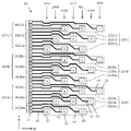
- FIG. 7 is an enlarged view showing a region corresponding to a portion H in FIG.
- the individual electrode wiring 19 is illustrated by a thick solid line.
- symbol may add the additional code
- a pad 20 is connected to the end of each individual electrode wiring 19, and the first connection terminal 11a of the drive IC 11 provided on the pad 20 is connected via solder or the like. They are connected (see FIG. 2).
- the pad 20 has a width larger than the line width of the individual electrode wiring 19, and has a size that allows the first connection terminal 11a to be connected by solder or the like as described above.
- the surface of the pad 20 may be plated with nickel or gold.
- the heat generating units 9 are continuously arranged along the first direction L, and the first heat generating unit group 901A, 901B, 901C is constituted by the continuous heat generating units 9.
- a plurality of heat generating units 9 constituting the first heat generating unit group 901A constitute second heat generating unit groups 902Aa, 902Ab, and 902Ac.
- the plurality of heat generating units 9 constituting the first heat generating unit group 901B constitute second heat generating unit groups 902Ba, 902Bb, and 902Bc.
- the plurality of heat generating units 9 constituting the first heat generating unit group 901C constitute second heat generating unit groups 902Ca, 902Cb, 902Cc.
- the plurality of pads 20 are provided in the first direction L, and have first pad groups 201A, 201B, and 201C configured by the plurality of pads 20.
- first pad group 201A a plurality of pads 20 constituting the first pad group 201A constitute second pad groups 202Aa, 202Ab, and 202Ac.
- the plurality of pads 20 constituting the first pad group 201B constitute second pad groups 202Ba, 202Bb, 202Bc.
- a plurality of pads 20 constituting the first pad group 201C constitute second pad groups 202Ca, 202Cb, 202Cc.
- the second pad groups 202 ⁇ / b> Aa, 202 ⁇ / b> Ab, 202 ⁇ / b> Ac are configured by the pads 20 arranged along the second direction W.
- the second pad group 202Aa is composed of pads 20a, 20b, and 20c.
- the second pad groups 202Aa, 202Ab, 202Ac are arranged along the first direction L.
- the second pad groups 202Aa, 202Ab, 202Ac are arranged in a state shifted in the second direction W, respectively. Therefore, the pads 20 configuring the second pad group 202 are provided in a step shape in which the distance from the heat generating portion 9 changes stepwise.
- the pads 20 constituting the second pad group 202 are arranged along the second direction W, and the second pad group 202 is arranged along the first direction L.
- the arrangement area of the pads 20 in the second direction W can be reduced.
- the length of the substrate 7 in the second direction W can be shortened, and the thermal head X1 can be miniaturized.
- the second pad group 202 is arranged along the second direction W, the arrangement area of the pads 20 in the first direction L can also be reduced.
- the length of the substrate 7 in the first direction L can be shortened, and the thermal head X1 can also be reduced in size in the first direction L. It is particularly effective in the high-density wiring type thermal head X1 in which the number of pads 20 is large and the arrangement area of the pads 20 tends to increase.
- the thermal head X1 can reduce the arrangement area of the pad 20 in the second direction W, the distance between the heat generating portion 9 and the pad 20 can be reduced as compared with the state in which the pads 20 according to the related art are arranged obliquely. Can be shortened. Specifically, the distance between the pad 20i located at the seventh stage far from the heat generating portion 9 and the heat generating portion 9i can be shortened as compared with the conventional case. Thereby, the distance between the pad 20i located at the seventh step far from the heat generating portion 9 and the heat generating portion 9i is set to the distance between the pad 20a located at the first step closer to the heat generating portion 9 and the heat generating portion 9a. You can get closer.
- the length of the individual electrode wiring 19 that electrically connects the heat generating portion 9i and the pad 20i can be made closer to the length of the individual electrode wiring 19 that electrically connects the heat generating portion 9a and the pad 20a. . Therefore, the difference in electrical resistance due to the length of the individual electrode wiring 19 between the heat generating portion 9a and the heat generating portion 9i can be reduced, and the difference in heat generation temperature of the heat generating portion 9 can be reduced.
- the thermal head X1 is disposed so that the second pad group 202 is shifted in the first direction L, in other words, away from the heat generating portion 9, so that even when many pads 20 are disposed, the individual electrode wiring 19 is provided. Can be wired with high density. That is, only the pads 20a constituting the second heat generating portion group 202Aa are arranged on the first stage, and only the pads 20d constituting the second heat generating portion group 202Ab are arranged on the second stage, and individual electrodes for the pads 20a and 20d are arranged.
- the thermal head X1 can be further downsized in the first direction L.
- the first pad group 201 is arranged in the first direction L.
- the second pad group 202 is arranged in the first direction L and is arranged shifted in the second direction W.
- the first pad group 201 has a specific pad arrangement, and the specific pad arrangement is repeatedly provided in the first direction L.
- the first pad group 201 has a specific pad arrangement and a plurality of pads are arranged in the first direction L, in the probe step of detecting the electrical connection between the heat generating portion 9 and the pad 20.
- the tact time of the probe process can be shortened. That is, a probe detection needle corresponding to a specific pad arrangement of the first pad group 201 is manufactured, and the probe process is performed for each first pad group 201, thereby performing the probe process for each pad 20.
- the tact time of the probe process can be shortened.
- the arrangement of the pads 20 will be described in more detail using the first pad group 201A.
- the thermal head X1 configures the second pad group 202Ab between the pads 20a, 20b, and 20c configuring the second pad group 202Aa when viewed from the first direction L in the adjacent second pad groups 202Aa and 201Ab.
- Pads 20d, 20e, and 20f are arranged. Therefore, the arrangement area of the pad 20 in the first direction L can be reduced.
- the second pad group 202Ba of the first pad group 201B is placed between the pads 20g, 20h, 20i constituting the second pad group 202Ac of the first pad group 201A.
- the pads 20a, 20b, and 20c to be configured may be arranged. In that case, the arrangement area of the pad 20 can be further reduced.
- the first pad group 201B may be shifted in the second direction W by one stage. Accordingly, the first pad groups 201A and 201C can be shifted from the adjacent first pad group 201B.
- the distance between the pads 20a, 20d, 20g located closest to the heat generating part 9 and the heat generating parts 9a, 9d, 9g is the first direction. As it goes to L, it becomes larger. Therefore, the lengths of the individual electrode wirings 19 connecting the adjacent heat generating portions 9c and 9d and the second pad groups 202Aa and 202Ab can be reduced. That is, the distance between the heat generating portion 9c and the pad 20c constituting the second pad group 202Aa and the distance between the heat generating portion 9d and the pad 20d constituting the second pad group 202Ab can be reduced, and the adjacent heat generating portions 9c.
- the adjacent heat generation part 9 shows the heat generation part 9 adjacent in the 1st direction L, and a voltage is applied continuously in the case of printing.
- the first direction L indicates the arrangement direction of the heat generating portions 9, and the second direction W is a direction different from the first direction L, preferably a direction orthogonal to the first direction L. Further, the fact that the second direction W is orthogonal to the first direction L is not limited to the angle between the first direction L and the second direction W being 90 degrees, and allows about ⁇ 5 degrees. It is a concept.
- the IC control wiring 23 is for controlling the driving IC 11 and includes an IC power wiring 23a and an IC signal wiring 23b as shown in FIGS.
- the IC power supply wiring 23a has an end power supply electrode part 23aE and an intermediate power supply electrode part 23aM.
- the end power supply electrode portion 23 a E is disposed in the vicinity of the long side on the right side of the substrate 7 at both ends in the longitudinal direction of the substrate 7.
- the intermediate power supply electrode portion 23bM is disposed between adjacent drive ICs 11.
- the end power supply wiring portion 23 a E has one end portion disposed in the region where the drive IC 11 is disposed and the other end portion of the other long side of the substrate 7, so that the other end portion wraps around the ground electrode wiring 21. It is arranged in the vicinity of 7b.
- the end power supply wiring portion 23aE has one end connected to the drive IC 11 and the other end connected to the FPC 5. Thereby, the drive IC 11 and the FPC 5 are electrically connected.
- the intermediate power supply wiring portion 23 a ⁇ / i> M extends along the ground electrode wiring 21, one end portion is arranged in one arrangement region of the adjacent drive IC 11, and the other end portion is the other of the adjacent drive IC 11. Arranged in the arrangement area.
- the intermediate power supply wiring portion 23aM has one end connected to one of the adjacent drive ICs 11, the other end connected to the other of the adjacent drive ICs 11, and the intermediate connected to the FPC 5 (see FIG. 3). Thereby, the drive IC 11 and the FPC 5 are electrically connected.
- the end power supply wiring portion 23aE and the intermediate power supply wiring portion 23aM are electrically connected inside the drive IC 11 to which both of them are connected.
- the adjacent intermediate power supply wiring portions 23aM are electrically connected inside the drive IC 11 to which both of them are connected.
- the IC power supply wiring 23a is electrically connected between each drive IC 11 and the FPC 5.
- a current is supplied from the FPC 5 to each drive IC 11 via the end power supply wiring portion 23aE and the intermediate power supply wiring portion 23aM.
- the IC signal wiring 23 b is adjacent to the end signal wiring portion 23 b E arranged in the vicinity of the other long side 7 b of the substrate 7 at both ends in the longitudinal direction of the substrate 7 and the adjacent driving IC 11. And an intermediate signal wiring portion 23bM disposed therebetween.
- the end signal wiring portion 23bE has one end portion disposed in the region where the drive IC 11 is disposed and the other end of the ground electrode wiring 21 in the same manner as the end power supply wiring portion 23aE.
- the portion is disposed in the vicinity of the other long side 7 b of the substrate 7.
- the end signal wiring portion 23bE has one end connected to the drive IC 11 and the other end connected to the FPC 5.
- the intermediate signal wiring portion 23bM is arranged in one arrangement region of the adjacent driving IC 11 with one end portion thereof, and is arranged in the other arrangement region of the adjacent driving IC 11 with the other end portion thereof so as to wrap around the intermediate power supply wiring portion 23aM. Has been placed.
- the intermediate signal wiring portion 23bM has one end connected to one of the adjacent drive ICs 11 and the other end connected to the other of the adjacent drive ICs 11.
- the end signal wiring portion 23bE and the intermediate signal wiring portion 23bM are electrically connected inside the drive IC 11 to which both of them are connected. Further, the adjacent intermediate signal wiring portions 23bM are electrically connected inside the drive IC to which both of them are connected.
- the IC signal wiring 23b is electrically connected between each driving IC 11 and the FPC 5.
- the control signal transmitted from the FPC 5 to the drive IC 11 via the end signal wiring portion 23bE is further transmitted to the adjacent drive IC 11 via the intermediate signal wiring portion 23bM. .
- the electrical resistance layer 15, the common electrode wiring 17, the individual electrode wiring 19, the ground electrode wiring 21, and the IC control wiring 23 are conventionally well-known, for example, by forming a material layer constituting each on the heat storage layer 13, for example, sputtering. After sequentially laminating by the thin film forming technique, the laminated body is processed into a predetermined pattern using a conventionally known photolithography technique or etching technique.
- a first protective layer covering the heat generating portion 9, a part of the common electrode wiring 17 and a part of the individual electrode wiring 19. 25 is formed on the heat storage layer 13 formed on the upper surface of the substrate 7.
- the first protective layer 25 is formed along the arrangement direction of the plurality of heat generating units 9 and is provided so as to cover a substantially left half region of the upper surface of the heat storage layer 13.
- the first protective layer 25 suppresses oxidation of the coated heat generating portion 9, the common electrode wiring 17 and the individual electrode wiring 19 due to the reaction with oxygen, or adheres moisture or the like contained in the atmosphere. It is intended to suppress the possibility of being corroded by the above-mentioned, or to reduce the possibility of being worn by contact with the medium to be printed.
- the first protective layer 25 can be formed of, for example, a SiC-based material, a SiN-based material, a SiO-based material, or a SiON-based material.
- the first protective layer 25 can be formed by using a conventionally well-known thin film forming technique such as a sputtering method or a vapor deposition method or a thick film forming technique such as a screen printing method.
- the first protective layer 25 may be formed by stacking a plurality of material layers.
- the common electrode wiring 17, the individual electrode wiring 19, the IC control wiring 23, and the ground electrode wiring 21 are partially covered on the heat storage layer 13 formed on the upper surface of the substrate 7.
- a second protective layer 27 is provided.
- the 2nd protective layer 27 is provided so that the area
- the second protective layer 27 is formed by oxidizing the coated common electrode wiring 17, individual electrode wiring 19, IC control wiring 23 and ground electrode wiring 21 by contact with the atmosphere or adhesion of moisture contained in the atmosphere. It is intended to protect against corrosion.
- the second protective layer 27 is formed so as to overlap the end portion of the first protective layer 25 in order to ensure the protection of the common electrode wiring 17, the individual electrode wiring 19 and the IC control wiring 23.
- the second protective layer 27 can be formed of a resin material such as an epoxy resin or a polyimide resin, for example.
- the second protective layer 27 can be formed using a thick film forming technique such as a screen printing method, for example.
- the second protective layer 27 exposes the end portions of the individual electrode wiring 19 that connects the driving IC 11, the second intermediate region 21 N and the third intermediate region 21 L of the ground electrode wiring 21, and the end portion of the IC control wiring 23.
- an opening (not shown) is formed, and these wirings are connected to the drive IC 11 through the opening.
- the drive IC 11 is connected to the individual electrode wiring 19, the ground electrode wiring 21, and the IC control wiring 23 to protect the drive IC 11 itself and to protect the connection portion between the drive IC 11 and these wirings. It is covered and sealed with a covering member 29 made of resin such as resin or silicone resin.
- the FPC 5 is connected to the common electrode wiring 17, the ground electrode wiring 21, and the IC control wiring 23 as described above, as shown in FIG.
- the FPC 5 is a well-known one in which a plurality of printed wirings are wired inside an insulating resin layer, and each printed wiring is connected via a connector 31 (see FIGS. 1 and 6) to an external power supply device and control (not shown). It is electrically connected to a device or the like.
- each printed wiring formed therein is soldered by solder 33 (see FIG. 3), the end of the sub-wiring portion 17b of the common electrode wiring 17, the end of the ground electrode wiring 21, and the IC control.
- the common electrode wiring 17, the ground electrode wiring 21, the IC control wiring 23, and the connector 31 are connected to the ends of the wiring 23.
- the common electrode wiring 17 is connected to the positive terminal of the power supply device held at a positive potential of 20 to 24 V, for example. Is done.
- the individual electrode wiring 19 is connected to the negative terminal of the power supply device held at a ground potential of 0 to 1 V, for example. For this reason, when the switching element of the drive IC 11 is in the on state, a current is supplied to the heat generating portion 9 and the heat generating portion 9 generates heat.
- the IC power supply wiring 23a of the IC control wiring 23 is a power supply held at a positive potential, like the common electrode wiring 17. Connected to the positive terminal of the device. As a result, a current for operating the drive IC 11 is supplied to the drive IC 11 by the potential difference between the IC power supply wiring 23 a to which the drive IC 11 is connected and the ground electrode wiring 21.
- the IC signal wiring 23 b of the IC control wiring 23 is connected to a control device that controls the driving IC 11.
- the control signal from the control device is transmitted to the drive IC 11 via the end signal wiring portion 23bE, and the control signal transmitted to the drive IC 11 is further transmitted to the adjacent drive IC via the intermediate signal wiring portion 23bM. Is done.
- the heat generating portion 9 can be selectively heated.
- FIG. 8 is a schematic configuration diagram of the thermal printer Z of the present embodiment.
- the thermal printer Z includes the thermal head X1, the transport mechanism 40, the platen roller 50, the power supply device 60, and the control device 70 described above.
- the thermal head X1 is attached to an attachment surface 80a of an attachment member 80 provided in a housing (not shown) of the thermal printer Z.
- the thermal head X1 is mounted on the mounting member so that the arrangement direction of the heat generating portions 9 is along a direction (main scanning direction) (direction perpendicular to the paper surface of FIG. 8) perpendicular to the conveyance direction S of the medium P described later. 80 is attached.
- the transport mechanism 40 transports a medium P such as thermal paper or image receiving paper onto which ink is transferred in the direction of arrow S in FIG. 8, and then on the plurality of heat generating portions 9 of the thermal head X (more specifically, the protective layer 25. It is for conveying to the upper side, and has conveying rollers 43, 45, 47, and 49.
- the transport rollers 43, 45, 47, and 49 are formed by, for example, covering cylindrical shaft bodies 43a, 45a, 47a, and 49a made of metal such as stainless steel with elastic members 43b, 45b, 47b, and 49b made of butadiene rubber or the like. Can be configured.
- the medium P is an image receiving paper or the like to which ink is transferred, an ink film is transported together with the medium P between the medium P and the heat generating portion 9 of the thermal head X1.
- the platen roller 50 is for pressing the medium P onto the heat generating portion 9 of the thermal head X1, and is arranged so as to extend along a direction orthogonal to the conveyance direction S of the medium P. Both ends are supported so as to be rotatable while pressed upward.
- the platen roller 50 can be configured by, for example, covering a cylindrical shaft body 50a made of metal such as stainless steel with an elastic member 50b made of butadiene rubber or the like.
- the power supply device 60 is for supplying a current for causing the heat generating portion 9 of the thermal head X1 to generate heat and a current for operating the driving IC 11 as described above.
- the control device 70 is for supplying a control signal for controlling the operation of the drive IC 11 to the drive IC 11 in order to selectively generate heat in the heat generating portion 9 of the thermal head X1 as described above.
- the thermal printer Z presses the medium onto the heat generating part 9 of the thermal head X1 by the platen roller 50 and conveys the medium P onto the heat generating part 9 by the transport mechanism 40.
- the heat generating unit 9 By selectively causing the heat generating unit 9 to generate heat by the power supply device 60 and the control device 70, predetermined printing can be performed on the medium P.
- the medium P is an image receiving paper or the like
- printing on the medium P can be performed by thermally transferring ink of an ink film (not shown) conveyed together with the medium P to the medium P.
- a thermal head X2 according to the second embodiment will be described with reference to FIG.
- the first pad group 201 is arranged in the first direction L
- the second pad group 202 is arranged in the first direction L
- This is the same as the thermal head X1
- the order of connection between each pad 20 constituting the second pad group 202 and the heat generating portion 9 is different from that of the thermal head X1.
- the second pad group 202Aa is connected to the second heat generating part group 902Aa, and the heat generating part 9a is connected to the pad 20a located at the fifth level. Moreover, the heat generating part 9b adjacent to the heat generating part 9a and the pad 20b located at the third level are connected. Further, the heat generating part 9c adjacent to the heat generating part 9b and the pad 20c located in the first stage are connected. That is, the pads 20a, 20b, 20c constituting the second pad group 202Aa are connected to the heat generating portions 9a, 9b, 9c in order from the longer distance between the pads 20a, 20b, 20c and the heat generating portions 9a, 9b, 9c. Has been. The same applies to the second pad groups 202Ab and 202Ac.
- the pad 20i connected to the heat generating portion 9i disposed at the end of the first heat generating portion 901A and the first heat generating The configuration is such that the distance from the pad 20a connected to the heat generating portion 9a disposed at the beginning of the portion 901B is short.
- the length of the individual electrode wiring 19 that connects the heat generating part 9i disposed at the end of the first heat generating part 901A and the pad 20i is larger than that in the case where the conventional pads 20 are arranged obliquely.
- the length of the individual electrode wiring 19 that connects the heat generating portion 9a and the pad 20a disposed at the beginning of 901B can be approached. Therefore, the electrical resistance caused by the individual electrode wiring 19 connected to the heat generating portions 9i and 9a, which are the continuous heat generating portions 9, can be brought close, and the heat generating temperatures of the heat generating portions 9i and 9a can be made close.
- a thermal head X3 according to the third embodiment will be described with reference to FIG.
- the thermal head X3 is provided with a wide portion 24 in a part of the individual electrode wiring 19, and among the pads 20 constituting the first pad group 201, the pad arranged at the position where the distance from the heat generating portion 9 is the longest.
- the configuration is different from the thermal head X2 in that the auxiliary electrode 22 is provided in the width direction of the pad, and the other points are the same as the thermal head X2.
- the thermal head X3 is provided with a wide portion 24 in a part of the individual electrode wiring 19. Specifically, the wide portion 24 is provided in the individual electrode wiring 19 in the fifth and subsequent stages. As a result, an increase in electrical resistance that increases due to an increase in the length of the individual electrode wiring 19 can be reduced.
- the wide portion 24 is a portion that is wider than the portion of the other individual electrode wiring 19 and has a function of reducing electrical resistance due to its wide width.
- the width of the wide portion 24 may be changed depending on the step where the individual electrode wiring 19 is located.
- the width of the wide portion 24 provided in the fifth step is larger than the width of the wide portion 24 provided in the fourth step. It may be provided as follows. As the distance from the heat generating portion 9 in the second direction W increases, there is a margin in the arrangement region of the pad 20, so that the wide portion 24 is preferably increased in the second direction.
- auxiliary electrodes 22 are provided on the pads 20a, 20d, and 20g constituting the first pad groups 201A, 201B, and 201C.
- the pad located far from the heating part and the probe detection needle are not in contact with each other. It may not be detected that a failure may occur.
- the thermal head X3 since the auxiliary electrode 22 is provided on the pads 20a, 20d, and 20g constituting the first pad group 201A, 201B, and 201C, the probe that contacts the pads 20a, 20d, and 20g. Even when the position of the detection needle is slightly deviated, the probe inspection can be performed, and the possibility of detecting a defect regardless of the non-defective product can be reduced.
- the auxiliary electrode 22 can be formed of the same material as that of the individual electrode wiring 19, and can be formed simultaneously with the formation of the individual electrode wiring 19.
- the individual electrode wiring 19 may be provided integrally. That is, the size of the pads 20 a, 20 d, and 20 g configuring the first pad group 201 ⁇ / b> A, 201 ⁇ / b> B, and 201 ⁇ / b> C may be larger than that of the other pads 20.
- the pad 20 may be plated with Ni or Al, but the auxiliary electrode 22 may not be plated. Even if no plating is attached to the auxiliary electrode 22, it is possible to reduce the possibility of defects during the probe process.
- the thermal head X3 an example in which the thermal head X3 is provided only on the pads 20a, 20d, and 20g in the seventh stage is shown, but the present invention is not limited to this.
- the auxiliary electrode 22 may be provided on the pads 20a, 20b, 20h, and 20g after the fifth stage. Further, among the pads 20 constituting the second pad group 202, the auxiliary electrode 22 may be provided on the pads 20a, 20d, and 20g farthest from the heat generating portion 9. In any of the above cases, it is possible to reduce the possibility of defects occurring during the probe process.
- a thermal head X4 according to the fourth embodiment will be described with reference to FIG.
- the thermal head X4 in the first pad group 201A, the second pad groups 202Aa and 201Ac are connected to the heat generating part 9 and the pad 20 in order of increasing distance from the heat generating part 9.
- the heat generating portion 9 and the pad 20 are connected in order of increasing distance from the heat generating portion 9.
- Other configurations are the same as those of the thermal head X1, and the description thereof is omitted.
- the connection between the heat generating part 9 of the thermal head X4 and the pad 20 will be described using the first pad group 201A.
- the pads 20a, 20b, and 20c constituting the second pad group 202Aa are connected to the heat generating units 9a, 9b, and 9c in order of increasing distance from the heat generating unit 9. Therefore, the distance between the heat generating portions 9a, 9b, and 9c and the pads 20a, 20b, and 20c is configured to become shorter as the first direction L is advanced.
- the pads 20d, 20e, and 20f constituting the second pad group 202Ab are connected to the heat generating portions 9d, 9e, and 9f in order of increasing distance from the heat generating portion 9. Therefore, the distance between the heat generating portions 9d, 9e, and 9f and the pads 20d, 20e, and 20f becomes longer as the distance in the first direction L increases.
- the pads 20g, 20h, 20i constituting the second pad group 202Ac are connected to the heat generating portions 9g, 9h, 9i in order of increasing distance from the heat generating portion 9. Therefore, the distance between the heat generating portions 9g, 9h, and 9i and the pads 20g, 20h, and 20i is configured to become shorter as the first direction L is advanced. In other words, in the thermal head X4, the heat generating portion 9 and the pad 20 are connected so as to meander as they proceed in the first direction L.
- the distance between the heat generating portion 9 and the pad 20 is the length of the fifth step as it advances in the first direction L. Gradually decreases to the second stage length.
- the distance between the heat generating portion 9 and the pad 20 gradually increases from the length of the third step to the length of the sixth step.
- the distance between the heat generating portion 9 and the pad 20 is gradually reduced from the seventh step length to the third step length.
- the electric resistance due to the individual electrode wiring 19 between the adjacent heat generating portions 9 between the first pad groups 201A, 201B, and 201C. can be brought closer. Therefore, the heat generation temperature between the adjacent heat generating portions 9 can be made closer.
- the position of the pad 20i connected to the heat generating portion 9i located at the end of the first pad group 201A is the third level, and the pad connected to the heat generating portion 9a located at the first position of the first pad group 201b.
- the position of 20a becomes the fifth stage. Therefore, the electrical resistance of the adjacent heat generating portions 9 can be brought close to the boundary with the first pad group 201 as well.
- the position of the pad 20i connected to the heat generating part 9i located at the end of the first pad group 201A is the third level, and the position of the pad 20a connected to the heat generating part 9a located at the beginning of the first pad group 201b.
- the present invention is not limited to this example. For example, by shifting the first pad group 201B by two steps in the opposite direction to the second direction W, the position of the pad 20i connected to the heat generating part 9i located at the end of the first pad group 201A, and the first pad group 201B You may arrange
- the pad 20 when providing the pad 20 so that it may adjoin, it is preferable to provide in the same step
- the shape of the pad 20 is formed in a quadrangular shape, but is not limited thereto.
- the pad 20 may be formed in an arbitrary polygonal shape or a circular shape.
- each first heat generating unit group 901 is configured by nine heat generating units 9, and each second heat generating unit group 902 is configured by three heat generating units 9, and FIG. As shown, these are connected to the first pad group 201 and the second pad group 202, respectively, but the number of the plurality of heat generating portions 9 constituting the first heat generating portion group 901 and the second heat generating portion group 902 is as follows. It can be a plurality of arbitrary numbers. Further, the number of the first pad group 201 and the second pad group 202 may be determined according to the number of the plurality of heat generating units 9 constituting the first heat generating unit group and the second heat generating unit group.
- the thermal head X1 the example in which the first direction L and the second direction W are orthogonal to each other is shown, but the present invention is not limited to this. Since the second pad group only needs to be arranged in a direction away from the first direction L, the second direction W only needs to be different from the first direction L.
Abstract
Description
以下、本発明の第1の実施形態に係るサーマルヘッドのX1について、図面を参照しつつ説明する。図1~3に示すように、サーマルヘッドX1は、放熱体1と、放熱体1上に配置されたヘッド基体3と、ヘッド基体3に接続されたフレキシブルプリント配線板5(以下、FPC5と称する)とを備えている。 <First Embodiment>
Hereinafter, X1 of the thermal head according to the first embodiment of the present invention will be described with reference to the drawings. As shown in FIGS. 1 to 3, the thermal head X1 includes a
図9を用いて、第2の実施形態に係るサーマルヘッドX2について説明する。サーマルヘッドX2は、第1パッド群201が第1方向Lに配列されている点、第2パッド群202が第1方向Lに沿っており、第2方向Wにずれて配置されている点はサーマルヘッドX1と同様であり、第2パッド群202を構成する各パッド20と、発熱部9との接続の順序がサーマルヘッドX1と異なる。 <Second Embodiment>
A thermal head X2 according to the second embodiment will be described with reference to FIG. In the thermal head X2, the first pad group 201 is arranged in the first direction L, the second pad group 202 is arranged in the first direction L, and is shifted in the second direction W. This is the same as the thermal head X1, and the order of connection between each
図10を用いて第3の実施形態に係るサーマルヘッドX3について説明する。サーマルヘッドX3は、個別電極配線19の一部に幅広部24が設けられており、第1パッド群201を構成するパッド20のうち、発熱部9との距離が最も長い位置に配置されたパッドに、当該パッドの幅方向に補助電極22が設けられている点で、サーマルヘッドX2と構成が異なり、その他の点はサーマルヘッドX2と同様である。 <Third Embodiment>
A thermal head X3 according to the third embodiment will be described with reference to FIG. The thermal head X3 is provided with a
図11を用いて第4の実施形態に係るサーマルヘッドX4について説明する。サーマルヘッドX4は、第1パッド群201Aにおいて、第2パッド群202Aa,201Acが、発熱部9とパッド20とが、発熱部9との距離が遠い順に接続されている。第2パッド群202Abは、発熱部9とパッド20とが、発熱部9との距離が近い順に接続されている。その他の構成は、サーマルヘッドX1と同様であり、説明を省略する。 <Fourth Embodiment>
A thermal head X4 according to the fourth embodiment will be described with reference to FIG. In the thermal head X4, in the
1 放熱体
3 ヘッド基体
7 基板
9 発熱部
901 第1発熱部群
902 第2発熱部群
11 駆動IC
11a 第1接続端子
11b 第2接続端子
13 蓄熱層
13b 隆起部
15 電気抵抗層
17 共通電極配線
19 個別電極配線
20 パッド
201 第1パッド群
202 第2パッド群
22 補助電極
24 幅広部
25 第1保護層
27 第2保護層
L 第1方向
W 第2方向 X1, X2, X3,
11a
Claims (8)
- 基板と、
該基板上に設けられ、第1方向に配列された複数の発熱部と、
前記基板上に設けられ、前記発熱部の駆動を制御するための駆動ICと、
前記基板上に設けられ、前記駆動ICの複数の端子と電気的に接続するための複数のパッドと、
前記基板上に設けられ、複数の前記発熱部と複数の前記パッドとを電気的に接続する複数の配線と、を備え、
複数の前記パッドは、前記第1方向に複数設けられており、複数の前記パッドにより構成された複数の第1パッド群と、該第1パッド群を構成する複数の前記パッドにより構成された複数の第2パッド群とを有し、
該第2パッド群は、前記第1方向に複数設けられており、前記第1方向とは異なる第2方向にずれて配置されていることを特徴とするサーマルヘッド。 A substrate,
A plurality of heat generating portions provided on the substrate and arranged in a first direction;
A driving IC provided on the substrate for controlling the driving of the heat generating unit;
A plurality of pads provided on the substrate and electrically connected to a plurality of terminals of the driving IC;
A plurality of wirings provided on the substrate and electrically connecting the plurality of heat generating portions and the plurality of pads;
The plurality of pads are provided in the first direction, and a plurality of first pad groups constituted by the plurality of pads and a plurality of pads constituted by the plurality of pads constituting the first pad group. And a second pad group.
A thermal head, wherein a plurality of the second pad groups are provided in the first direction and are shifted in a second direction different from the first direction. - 前記第1パッド群において、複数の前記第2パッド群を構成する前記パッドのうち最も前記発熱部側に位置する前記パッドと前記発熱部との距離が、前記第1方向に進むにつれて大きくなっている、請求項1に記載のサーマルヘッド。 In the first pad group, the distance between the heat generating portion and the pad located closest to the heat generating portion among the pads constituting the plurality of second pad groups increases as the first direction proceeds. The thermal head according to claim 1.
- 前記第1パッド群における、隣り合う前記第2パッド群において、前記第1方向から見て、一方の前記第2パッド群を構成する前記パッドの間に、他方の前記第2パッド群を構成する前記パッドが配置されている、請求項1または2に記載のサーマルヘッド。 In the second pad groups adjacent to each other in the first pad group, the other second pad group is formed between the pads constituting one of the second pad groups when viewed from the first direction. The thermal head according to claim 1, wherein the pad is disposed.
- 複数の前記発熱部は、複数の前記第1パッド群と電気的に接続された複数の第1発熱部群を有し、
一方の前記第1発熱部群の最後に配置された前記発熱部に電気的に接続された一方の前記第1パッド群の前記パッドが、他方の前記第1発熱部群の最初に配置された前記発熱部と電気的に接続された他方の前記第1パッド群の前記パッドに隣り合って設けられている、請求項1乃至3のいずれか1項に記載のサーマルヘッド。 The plurality of heat generating units have a plurality of first heat generating unit groups electrically connected to the plurality of first pad groups,
The pad of one of the first pad groups electrically connected to the heat generating portion disposed at the end of one of the first heat generating portion groups is disposed at the beginning of the other first heat generating portion group. 4. The thermal head according to claim 1, wherein the thermal head is provided adjacent to the pad of the other first pad group that is electrically connected to the heat generating portion. 5. - 複数の前記発熱部は、複数の前記第1パッド群と電気的に接続された複数の第1発熱部群と、該第1発熱部群を構成する複数の前記発熱部により構成され、前記第2パッド群と電気的に接続された複数の第2発熱部群と、を有し、
前記第2パッド群を構成する複数の前記パッドは、当該パッドと前記発熱部との距離が長い方から順に、前記第2発熱部群を構成し連続する前記発熱部と電気的に接続されている、請求項1乃至4のいずれか1項に記載のサーマルヘッド。 The plurality of heat generating units are configured by a plurality of first heat generating unit groups electrically connected to the plurality of first pad groups, and the plurality of heat generating units constituting the first heat generating unit group, A plurality of second heat generating unit groups electrically connected to the two pad groups,
The plurality of pads constituting the second pad group are electrically connected to the successive heat generating parts constituting the second heat generating part group in order from the longest distance between the pads and the heat generating part. The thermal head according to any one of claims 1 to 4. - 前記配線の幅が、該配線と接続される前記パッドと前記発熱部との距離が長くなるにつれて大きい、請求項1乃至5のいずれか1項に記載のサーマルヘッド。 The thermal head according to any one of claims 1 to 5, wherein a width of the wiring increases as a distance between the pad connected to the wiring and the heat generating portion increases.
- 前記第1パッド群を構成する前記パッドのうち、前記発熱部との距離が最も長い位置に配置された前記パッドに、当該パッドの幅方向に補助電極が設けられている、請求項1乃至6のいずれか1項に記載のサーマルヘッド。 The auxiliary electrode is provided in the width direction of the said pad in the said pad arrange | positioned in the position where the distance with the said heat-generation part is longest among the said pads which comprise the said 1st pad group. The thermal head according to any one of the above.
- 請求項1乃至7のいずれか1項に記載のサーマルヘッドと、複数の前記発熱部上に媒体を搬送する搬送機構と、複数の前記発熱部上に前記媒体を押圧するプラテンローラとを備えることを特徴とするサーマルプリンタ。 8. The thermal head according to claim 1, a transport mechanism that transports a medium onto the plurality of heat generating units, and a platen roller that presses the medium onto the plurality of heat generating units. A thermal printer characterized by
Priority Applications (2)
| Application Number | Priority Date | Filing Date | Title |
|---|---|---|---|
| US14/007,590 US8953006B2 (en) | 2011-03-25 | 2012-03-23 | Thermal head and thermal printer provided with same |
| JP2012530810A JP5174287B1 (en) | 2011-03-25 | 2012-03-23 | Thermal head and thermal printer equipped with the same |
Applications Claiming Priority (2)
| Application Number | Priority Date | Filing Date | Title |
|---|---|---|---|
| JP2011-068184 | 2011-03-25 | ||
| JP2011068184 | 2011-03-25 |
Publications (1)
| Publication Number | Publication Date |
|---|---|
| WO2012133178A1 true WO2012133178A1 (en) | 2012-10-04 |
Family
ID=46930901
Family Applications (1)
| Application Number | Title | Priority Date | Filing Date |
|---|---|---|---|
| PCT/JP2012/057499 WO2012133178A1 (en) | 2011-03-25 | 2012-03-23 | Thermal head and thermal printer provided with same |
Country Status (3)
| Country | Link |
|---|---|
| US (1) | US8953006B2 (en) |
| JP (1) | JP5174287B1 (en) |
| WO (1) | WO2012133178A1 (en) |
Cited By (1)
| Publication number | Priority date | Publication date | Assignee | Title |
|---|---|---|---|---|
| WO2024004658A1 (en) * | 2022-06-30 | 2024-01-04 | ローム株式会社 | Thermal printhead, thermal printer, and method for producing thermal printhead |
Families Citing this family (2)
| Publication number | Priority date | Publication date | Assignee | Title |
|---|---|---|---|---|
| CN107405929B (en) * | 2015-03-27 | 2019-06-28 | 京瓷株式会社 | The manufacturing method of thermal head, thermal printer and thermal head |
| JP6875616B1 (en) * | 2019-11-22 | 2021-05-26 | 京セラ株式会社 | Thermal head and thermal printer |
Citations (9)
| Publication number | Priority date | Publication date | Assignee | Title |
|---|---|---|---|---|
| JPS58153672A (en) * | 1982-03-10 | 1983-09-12 | Nippon Telegr & Teleph Corp <Ntt> | Recording head with built-in thin film transistor circuit |
| JPS6463165A (en) * | 1987-09-02 | 1989-03-09 | Nec Corp | Thermal head |
| JPH0531955A (en) * | 1991-07-29 | 1993-02-09 | Ricoh Co Ltd | Semiconductor light emitting device |
| JPH05155056A (en) * | 1991-12-03 | 1993-06-22 | Rohm Co Ltd | Thermal head |
| JPH06166201A (en) * | 1992-11-30 | 1994-06-14 | Kyocera Corp | Thermal head |
| JP2000289250A (en) * | 1999-04-13 | 2000-10-17 | Oki Data Corp | Led array chip and led array print head |
| JP2002240336A (en) * | 2001-02-16 | 2002-08-28 | Toshiba Corp | Thermal head |
| JP2009148897A (en) * | 2007-12-18 | 2009-07-09 | Toshiba Hokuto Electronics Corp | Thermal print head and method for production thereof |
| JP2011025633A (en) * | 2009-07-29 | 2011-02-10 | Kyocera Corp | Wiring board, method for manufacturing the same, recording head and recorder |
Family Cites Families (6)
| Publication number | Priority date | Publication date | Assignee | Title |
|---|---|---|---|---|
| JPS5539341A (en) * | 1978-09-12 | 1980-03-19 | Mitsubishi Electric Corp | Heat-sensitive recording head |
| US5488394A (en) * | 1988-01-05 | 1996-01-30 | Max Levy Autograph, Inc. | Print head and method of making same |
| US5162191A (en) * | 1988-01-05 | 1992-11-10 | Max Levy Autograph, Inc. | High-density circuit and method of its manufacture |
| JPH02151452A (en) * | 1988-12-02 | 1990-06-11 | Ricoh Co Ltd | Electronic apparatus |
| JPH09150539A (en) * | 1995-11-29 | 1997-06-10 | Graphtec Corp | Thermal head |
| JP3537699B2 (en) | 1999-03-30 | 2004-06-14 | 京セラ株式会社 | Semiconductor element mounting structure |
-
2012
- 2012-03-23 JP JP2012530810A patent/JP5174287B1/en active Active
- 2012-03-23 WO PCT/JP2012/057499 patent/WO2012133178A1/en active Application Filing
- 2012-03-23 US US14/007,590 patent/US8953006B2/en active Active
Patent Citations (9)
| Publication number | Priority date | Publication date | Assignee | Title |
|---|---|---|---|---|
| JPS58153672A (en) * | 1982-03-10 | 1983-09-12 | Nippon Telegr & Teleph Corp <Ntt> | Recording head with built-in thin film transistor circuit |
| JPS6463165A (en) * | 1987-09-02 | 1989-03-09 | Nec Corp | Thermal head |
| JPH0531955A (en) * | 1991-07-29 | 1993-02-09 | Ricoh Co Ltd | Semiconductor light emitting device |
| JPH05155056A (en) * | 1991-12-03 | 1993-06-22 | Rohm Co Ltd | Thermal head |
| JPH06166201A (en) * | 1992-11-30 | 1994-06-14 | Kyocera Corp | Thermal head |
| JP2000289250A (en) * | 1999-04-13 | 2000-10-17 | Oki Data Corp | Led array chip and led array print head |
| JP2002240336A (en) * | 2001-02-16 | 2002-08-28 | Toshiba Corp | Thermal head |
| JP2009148897A (en) * | 2007-12-18 | 2009-07-09 | Toshiba Hokuto Electronics Corp | Thermal print head and method for production thereof |
| JP2011025633A (en) * | 2009-07-29 | 2011-02-10 | Kyocera Corp | Wiring board, method for manufacturing the same, recording head and recorder |
Cited By (1)
| Publication number | Priority date | Publication date | Assignee | Title |
|---|---|---|---|---|
| WO2024004658A1 (en) * | 2022-06-30 | 2024-01-04 | ローム株式会社 | Thermal printhead, thermal printer, and method for producing thermal printhead |
Also Published As
| Publication number | Publication date |
|---|---|
| JP5174287B1 (en) | 2013-04-03 |
| JPWO2012133178A1 (en) | 2014-07-28 |
| US8953006B2 (en) | 2015-02-10 |
| US20140022325A1 (en) | 2014-01-23 |
Similar Documents
| Publication | Publication Date | Title |
|---|---|---|
| JP5128010B1 (en) | Thermal head and thermal printer equipped with the same | |
| JP5174287B1 (en) | Thermal head and thermal printer equipped with the same | |
| JP2013226670A (en) | Thermal head and thermal printer with the same | |
| JP6130510B2 (en) | Thermal head and thermal printer equipped with the same | |
| JP2013028021A (en) | Thermal head and thermal printer having the same | |
| JP5964739B2 (en) | Thermal head and thermal printer equipped with the same | |
| JP2016137692A (en) | Thermal head and thermal printer comprising the same | |
| WO2012115231A1 (en) | Thermal head and thermal printer equipped with same | |
| JP6046872B2 (en) | Thermal head and thermal printer | |
| JP5840887B2 (en) | Thermal head and thermal printer equipped with the same | |
| JP5780715B2 (en) | Thermal head and thermal printer equipped with the same | |
| JP6154338B2 (en) | Thermal head and thermal printer | |
| JP6290632B2 (en) | Thermal head and thermal printer equipped with the same | |
| JP6208564B2 (en) | Thermal head and thermal printer | |
| JP5882613B2 (en) | Manufacturing method of thermal head | |
| JP2012030380A (en) | Thermal head and thermal printer equipped with the same | |
| JP5844550B2 (en) | Thermal head and thermal printer equipped with the same | |
| JP2012245711A (en) | Thermal head and thermal printer with the same | |
| JP6199814B2 (en) | Thermal head and thermal printer | |
| JP2017043013A (en) | Thermal head and thermal printer | |
| JP6075626B2 (en) | Thermal head and thermal printer | |
| JP5783709B2 (en) | Thermal head, thermal printer provided with the same, and method for manufacturing thermal head | |
| JP5665389B2 (en) | Thermal head and thermal printer equipped with the same | |
| JP2015182240A (en) | Thermal head and thermal printer | |
| JP2014188983A (en) | Thermal head and thermal printer provided with the same |
Legal Events
| Date | Code | Title | Description |
|---|---|---|---|
| ENP | Entry into the national phase |
Ref document number: 2012530810 Country of ref document: JP Kind code of ref document: A |
|
| 121 | Ep: the epo has been informed by wipo that ep was designated in this application |
Ref document number: 12763013 Country of ref document: EP Kind code of ref document: A1 |
|
| NENP | Non-entry into the national phase |
Ref country code: DE |
|
| WWE | Wipo information: entry into national phase |
Ref document number: 14007590 Country of ref document: US |
|
| 122 | Ep: pct application non-entry in european phase |
Ref document number: 12763013 Country of ref document: EP Kind code of ref document: A1 |