WO2012132135A1 - 電池パック - Google Patents
電池パック Download PDFInfo
- Publication number
- WO2012132135A1 WO2012132135A1 PCT/JP2011/079134 JP2011079134W WO2012132135A1 WO 2012132135 A1 WO2012132135 A1 WO 2012132135A1 JP 2011079134 W JP2011079134 W JP 2011079134W WO 2012132135 A1 WO2012132135 A1 WO 2012132135A1
- Authority
- WO
- WIPO (PCT)
- Prior art keywords
- battery pack
- battery
- outer case
- exterior
- case
- Prior art date
Links
- 239000011347 resin Substances 0.000 claims description 7
- 229920005989 resin Polymers 0.000 claims description 7
- 229910052751 metal Inorganic materials 0.000 claims description 6
- 239000002184 metal Substances 0.000 claims description 6
- 230000017525 heat dissipation Effects 0.000 abstract description 17
- 239000000112 cooling gas Substances 0.000 description 9
- 239000013307 optical fiber Substances 0.000 description 9
- 230000008901 benefit Effects 0.000 description 8
- 238000001816 cooling Methods 0.000 description 8
- 238000001514 detection method Methods 0.000 description 7
- 239000000758 substrate Substances 0.000 description 5
- 230000002950 deficient Effects 0.000 description 4
- 239000000428 dust Substances 0.000 description 4
- 239000000463 material Substances 0.000 description 4
- HBBGRARXTFLTSG-UHFFFAOYSA-N Lithium ion Chemical compound [Li+] HBBGRARXTFLTSG-UHFFFAOYSA-N 0.000 description 3
- 230000000694 effects Effects 0.000 description 3
- 229910001416 lithium ion Inorganic materials 0.000 description 3
- 238000000034 method Methods 0.000 description 3
- 230000002159 abnormal effect Effects 0.000 description 2
- 238000005452 bending Methods 0.000 description 2
- 238000000465 moulding Methods 0.000 description 2
- 230000002093 peripheral effect Effects 0.000 description 2
- WHXSMMKQMYFTQS-UHFFFAOYSA-N Lithium Chemical compound [Li] WHXSMMKQMYFTQS-UHFFFAOYSA-N 0.000 description 1
- 230000005540 biological transmission Effects 0.000 description 1
- 238000004891 communication Methods 0.000 description 1
- 239000000470 constituent Substances 0.000 description 1
- 238000010586 diagram Methods 0.000 description 1
- 238000007599 discharging Methods 0.000 description 1
- 230000020169 heat generation Effects 0.000 description 1
- 238000009413 insulation Methods 0.000 description 1
- 229910052744 lithium Inorganic materials 0.000 description 1
- 229910052987 metal hydride Inorganic materials 0.000 description 1
- 230000004048 modification Effects 0.000 description 1
- 238000012986 modification Methods 0.000 description 1
- 229910052759 nickel Inorganic materials 0.000 description 1
- PXHVJJICTQNCMI-UHFFFAOYSA-N nickel Substances [Ni] PXHVJJICTQNCMI-UHFFFAOYSA-N 0.000 description 1
- -1 nickel metal hydride Chemical class 0.000 description 1
- 229920000642 polymer Polymers 0.000 description 1
- 230000005855 radiation Effects 0.000 description 1
- 239000004065 semiconductor Substances 0.000 description 1
- 238000009423 ventilation Methods 0.000 description 1
- 239000013585 weight reducing agent Substances 0.000 description 1
Images


Classifications
-
- H—ELECTRICITY
- H01—ELECTRIC ELEMENTS
- H01M—PROCESSES OR MEANS, e.g. BATTERIES, FOR THE DIRECT CONVERSION OF CHEMICAL ENERGY INTO ELECTRICAL ENERGY
- H01M10/00—Secondary cells; Manufacture thereof
- H01M10/60—Heating or cooling; Temperature control
- H01M10/61—Types of temperature control
- H01M10/613—Cooling or keeping cold
-
- H—ELECTRICITY
- H01—ELECTRIC ELEMENTS
- H01M—PROCESSES OR MEANS, e.g. BATTERIES, FOR THE DIRECT CONVERSION OF CHEMICAL ENERGY INTO ELECTRICAL ENERGY
- H01M10/00—Secondary cells; Manufacture thereof
- H01M10/60—Heating or cooling; Temperature control
- H01M10/62—Heating or cooling; Temperature control specially adapted for specific applications
- H01M10/627—Stationary installations, e.g. power plant buffering or backup power supplies
-
- H—ELECTRICITY
- H01—ELECTRIC ELEMENTS
- H01M—PROCESSES OR MEANS, e.g. BATTERIES, FOR THE DIRECT CONVERSION OF CHEMICAL ENERGY INTO ELECTRICAL ENERGY
- H01M10/00—Secondary cells; Manufacture thereof
- H01M10/60—Heating or cooling; Temperature control
- H01M10/64—Heating or cooling; Temperature control characterised by the shape of the cells
- H01M10/643—Cylindrical cells
-
- H—ELECTRICITY
- H01—ELECTRIC ELEMENTS
- H01M—PROCESSES OR MEANS, e.g. BATTERIES, FOR THE DIRECT CONVERSION OF CHEMICAL ENERGY INTO ELECTRICAL ENERGY
- H01M10/00—Secondary cells; Manufacture thereof
- H01M10/60—Heating or cooling; Temperature control
- H01M10/65—Means for temperature control structurally associated with the cells
- H01M10/656—Means for temperature control structurally associated with the cells characterised by the type of heat-exchange fluid
- H01M10/6561—Gases
- H01M10/6563—Gases with forced flow, e.g. by blowers
-
- H—ELECTRICITY
- H01—ELECTRIC ELEMENTS
- H01M—PROCESSES OR MEANS, e.g. BATTERIES, FOR THE DIRECT CONVERSION OF CHEMICAL ENERGY INTO ELECTRICAL ENERGY
- H01M50/00—Constructional details or processes of manufacture of the non-active parts of electrochemical cells other than fuel cells, e.g. hybrid cells
- H01M50/20—Mountings; Secondary casings or frames; Racks, modules or packs; Suspension devices; Shock absorbers; Transport or carrying devices; Holders
- H01M50/204—Racks, modules or packs for multiple batteries or multiple cells
- H01M50/207—Racks, modules or packs for multiple batteries or multiple cells characterised by their shape
- H01M50/213—Racks, modules or packs for multiple batteries or multiple cells characterised by their shape adapted for cells having curved cross-section, e.g. round or elliptic
-
- H—ELECTRICITY
- H01—ELECTRIC ELEMENTS
- H01M—PROCESSES OR MEANS, e.g. BATTERIES, FOR THE DIRECT CONVERSION OF CHEMICAL ENERGY INTO ELECTRICAL ENERGY
- H01M50/00—Constructional details or processes of manufacture of the non-active parts of electrochemical cells other than fuel cells, e.g. hybrid cells
- H01M50/20—Mountings; Secondary casings or frames; Racks, modules or packs; Suspension devices; Shock absorbers; Transport or carrying devices; Holders
- H01M50/218—Mountings; Secondary casings or frames; Racks, modules or packs; Suspension devices; Shock absorbers; Transport or carrying devices; Holders characterised by the material
- H01M50/22—Mountings; Secondary casings or frames; Racks, modules or packs; Suspension devices; Shock absorbers; Transport or carrying devices; Holders characterised by the material of the casings or racks
- H01M50/222—Inorganic material
- H01M50/224—Metals
-
- H—ELECTRICITY
- H01—ELECTRIC ELEMENTS
- H01M—PROCESSES OR MEANS, e.g. BATTERIES, FOR THE DIRECT CONVERSION OF CHEMICAL ENERGY INTO ELECTRICAL ENERGY
- H01M50/00—Constructional details or processes of manufacture of the non-active parts of electrochemical cells other than fuel cells, e.g. hybrid cells
- H01M50/20—Mountings; Secondary casings or frames; Racks, modules or packs; Suspension devices; Shock absorbers; Transport or carrying devices; Holders
- H01M50/218—Mountings; Secondary casings or frames; Racks, modules or packs; Suspension devices; Shock absorbers; Transport or carrying devices; Holders characterised by the material
- H01M50/22—Mountings; Secondary casings or frames; Racks, modules or packs; Suspension devices; Shock absorbers; Transport or carrying devices; Holders characterised by the material of the casings or racks
- H01M50/227—Organic material
-
- H—ELECTRICITY
- H01—ELECTRIC ELEMENTS
- H01M—PROCESSES OR MEANS, e.g. BATTERIES, FOR THE DIRECT CONVERSION OF CHEMICAL ENERGY INTO ELECTRICAL ENERGY
- H01M2220/00—Batteries for particular applications
- H01M2220/10—Batteries in stationary systems, e.g. emergency power source in plant
-
- H—ELECTRICITY
- H01—ELECTRIC ELEMENTS
- H01M—PROCESSES OR MEANS, e.g. BATTERIES, FOR THE DIRECT CONVERSION OF CHEMICAL ENERGY INTO ELECTRICAL ENERGY
- H01M50/00—Constructional details or processes of manufacture of the non-active parts of electrochemical cells other than fuel cells, e.g. hybrid cells
- H01M50/50—Current conducting connections for cells or batteries
- H01M50/502—Interconnectors for connecting terminals of adjacent batteries; Interconnectors for connecting cells outside a battery casing
- H01M50/503—Interconnectors for connecting terminals of adjacent batteries; Interconnectors for connecting cells outside a battery casing characterised by the shape of the interconnectors
-
- Y—GENERAL TAGGING OF NEW TECHNOLOGICAL DEVELOPMENTS; GENERAL TAGGING OF CROSS-SECTIONAL TECHNOLOGIES SPANNING OVER SEVERAL SECTIONS OF THE IPC; TECHNICAL SUBJECTS COVERED BY FORMER USPC CROSS-REFERENCE ART COLLECTIONS [XRACs] AND DIGESTS
- Y02—TECHNOLOGIES OR APPLICATIONS FOR MITIGATION OR ADAPTATION AGAINST CLIMATE CHANGE
- Y02E—REDUCTION OF GREENHOUSE GAS [GHG] EMISSIONS, RELATED TO ENERGY GENERATION, TRANSMISSION OR DISTRIBUTION
- Y02E60/00—Enabling technologies; Technologies with a potential or indirect contribution to GHG emissions mitigation
- Y02E60/10—Energy storage using batteries
Definitions
- the present invention relates to a battery pack in which a plurality of rechargeable cells are housed in an outer case, and more particularly to a battery pack in which an outer case and a battery holder are integrated.
- the battery pack can increase the output voltage by connecting a large number of unit cells in series, and can increase the output current by connecting them in parallel.
- the number of cells to be accommodated has increased, while there is also a need to reduce the size of the battery pack. Therefore, the cells are closely arranged in a limited space of the outer case. There is a need.
- a unit cell generates heat when charged and discharged with a large current, and it is necessary to dispose a power semiconductor element such as a transistor or a diode for charging and discharging, and it is important to ensure heat dissipation.
- FIG. 14 shows an exploded perspective view of the battery pack previously developed by the present inventor.
- This battery pack includes a battery block 810 including a plurality of unit cells 811 and battery holders 815 and 816 provided with a battery storage unit 813 for storing each unit cell 811 individually, and a unit cell 811 of the battery block 810.
- a main circuit board 840 connected to the main circuit board, a heat generating component 841 connected to the main circuit board 840, a flat heat dissipation block 842 that fixes the heat generating component 841 in a thermally coupled state, a heat dissipation block 842, and a battery Exterior cases 831 and 832 that house the block 810 inside are provided.
- a unit cell is stored in a battery holder to constitute a battery block, a lead plate is welded to a side surface, and a circuit board is further disposed and stored in an outer case.
- the battery holder is divided into two and holds the unit cell so as to be sandwiched from both sides. For this reason, each of the divided battery holders fixes a plurality of cylindrical battery holding cylinders that accommodate the unit cells.
- the present invention has been made in view of such a background.
- the main objective of this invention is to provide the battery pack which can improve the heat dissipation of a unit cell and can perform an assembly operation
- a plurality of unit cells 11 whose outer appearance extended in one direction is substantially cylindrical, and the plurality of unit cells 11 are A first outer case 12A having a substantially rectangular outer shape provided with a plurality of substantially cylindrical battery accommodating portions 13 for individually accommodating, and a battery accommodating portion 13 for individually accommodating a plurality of unit cells 11. Is provided on the inner surface, and is joined to the first outer case 12A to hold the plurality of unit cells 11 so as to be sandwiched from both sides in the longitudinal direction. 12B, and the battery storage unit 13 can provide a gap GP between the battery storage unit 13 and the adjacent battery storage unit 13.
- the double structure which accommodates a battery holder in an exterior case is abolished, and it becomes possible to hold a unit cell directly in an exterior case.
- a number of parts can be reduced and it can contribute to cost reduction and weight reduction.
- the battery holder and the outer case are integrally formed, it is possible to obtain an advantage that the work efficiency at the time of assembly can be improved by incorporating a lead plate or the like into the outer case in advance.
- each of the first outer case 12A and the second outer case 12B is provided with an open frame 19 communicated with each battery storage portion 13,
- the battery pack further includes a first exterior panel 30A and a second exterior panel 30B having thermal conductivity for closing the open frames 19 provided in the first exterior case 12A and the second exterior case 12B, respectively. be able to.
- each of the first exterior panel 30A and the second exterior panel 30B can open a plurality of slits.
- the unit cell which has been conventionally surrounded by the outer case and the battery holder and has been difficult to dissipate to the outside, can be communicated with the outside through the open frame of the outer case and the slit of the outer panel. Benefits that can be improved.
- the battery pack of the fourth aspect of the present invention at least one of the first outer case 12A and the second outer case 12B has a first vent hole 14 on the first surface constituting a rectangular shape.
- the second vent 15 is opened on the second surface opposite to the first surface, and the battery pack has the first vent 14 and the second vent 15 substantially vertical. It can be held in a posture that opens in the direction.
- the battery pack is arranged so that the first vent and the second vent provided on the opposing surface are opened in a substantially vertical direction, and moved upward by natural convection of heat inside the exterior case. It can be configured that air is discharged from the vent opening opened upward, fresh fresh air is taken in from the vent opening opened downward, and natural heat dissipation is achieved.
- the first surface and the second surface can intersect with the surface provided with the opening surface.
- the side surface of the unit cell can be cooled by the cooling gas flowing in the first vent and the second vent, and the structure that can efficiently radiate the periphery of the unit cell realizable.
- the battery pack of the sixth aspect of the present invention at least one of the first exterior case 12A and the second exterior case 12B is recessed from the surface of the third surface on the third surface.
- the battery pack is held in such a posture that the third surface provided with the inclined surface 24a is a substantially vertical surface, and the inclined surface 24a further includes the first inclined surface 24a. It is inclined from the three flat surfaces in a direction away from the upper surface, and a connector portion 16 for connecting to an external device can be provided on the end surface of the inclined surface 24a.
- the first outer case 12A and the second outer case 12B are made of resin, and the first insulating sheet 25A and the second insulating sheet 25B are heated.
- the first exterior panel 30 ⁇ / b> A and the second exterior panel 30 ⁇ / b> B can be made of metal with high conductivity and insulating resin.
- the exterior case is made insulative, the part that easily exhibits the heat dissipation of the unit cell uses an insulating resin sheet having high thermal conductivity for the insulating sheet, and further, the exterior panel is made of metal to exhibit the heat dissipation. .
- FIG. 3 is a perspective view from the front surface of the battery pack according to Embodiment 1.
- FIG. It is a perspective view from the back of the battery pack which concerns on FIG.
- FIG. 4 is an exploded perspective view showing the internal structure of the battery pack when FIG. 3 is viewed from the back.
- 3 is a perspective view of an exterior case according to Embodiment 1.
- FIG. 4 is an exploded perspective view showing an internal structure of the exterior case according to Embodiment 1.
- FIG. FIG. 3 is an enlarged front view of a part of the outer side surface of the exterior case according to the first embodiment. It is a disassembled perspective view which shows the internal structure of the battery pack which concerns on a modification.
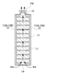
- FIG. 3 is a central cross-sectional view in the battery pack according to Embodiment 1 and an enlarged cross-sectional view of a battery storage unit.
- FIG. 3 is a perspective view from the bottom surface of the battery pack according to Embodiment 1 and an enlarged oblique view of a vent hole.
- 3 is a schematic diagram of a cooling example of the battery pack according to Embodiment 1.
- FIG. It is the perspective view from the bottom face of the battery pack which concerns on Embodiment 1, and the expansion perspective view of the connector part for information communication.
- It is a perspective view of a power supply rack and a battery pack. It is the perspective view which expand
- each element constituting the present invention may be configured such that a plurality of elements are constituted by the same member and the plurality of elements are shared by one member, and conversely, the function of one member is constituted by a plurality of members. It can also be realized by sharing.
- the contents described in some examples and embodiments may be used in other examples and embodiments.
- the battery pack of the present invention can be used as a stationary power storage facility, for example, as a power source for home use or factory use, and can be applied to a power supply system that is charged with sunlight or midnight power and discharged when necessary.
- a power supply system can be constructed by connecting a plurality of battery packs and connecting them in series and / or in parallel to increase the output.
- the power supply system connects a plurality of battery packs in a daisy chain, connects a controller to the end, and controls each battery pack.
- it can also be used as a power source for street lights that charge sunlight during the day and discharge at night, or as a backup power source for traffic lights that are driven in the event of a power failure.
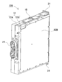
- FIG. 1 is an external perspective view of the battery pack 100.
- the battery pack 100 can be inserted into a power supply rack or the like in a standing state and fixed with the rack fixing bracket 31.
- a connector portion 16 is provided at the upper part of the side surface of the battery pack 100, and a cylindrical exhaust port 15 is provided at the upper part.
- FIG. 2 shows an external perspective view of the battery pack 100 as viewed from the back of FIG.
- the connection terminal 21 for taking out a power supply output outside is provided on the back surface of the battery pack 100.
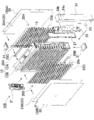
- FIG. 3 is an exploded perspective view showing the internal structure of the battery pack 100 according to FIG. 1
- FIG. 4 is an exploded perspective view showing the internal structure of the battery pack 100 when FIG. 3 is viewed from the back.
- the unit cell 11 is housed in an exterior case 12, a plurality of lead plates 20A and 20B are fixed on both sides, and further covered with an exterior panel 30 from both outer sides.
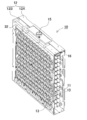
- FIG. 5 is a perspective view of the exterior case 12 with the exterior panel and lead plate removed
- FIG. 6 is an exploded perspective view of the exterior case 12.
- the outer case 12 is divided into two in the vertical direction, a first outer case 12A and a second outer case 12B, and the unit cell 11 is held between them.
- each of the first outer case 12A and the second outer case 12B is provided with a cylindrical battery storage portion 13 on the inner surface for individually storing the columnar unit cells 11.
- a first vent 14 is provided on the bottom surface of the first exterior case 12A, and a second vent 15 is provided on the top surface.
- the second outer case 12B is provided with a fuse cover 32 that covers the fuse FU.
- the battery storage unit 13 is provided so as to protrude substantially perpendicularly from the main surfaces of the first outer case 12A and the second outer case 12B.
- the length of each battery storage portion 13 is about 3 of the length of the unit cell 11.
- the unit cell 11 can be directly held by the outer case 12 without using an inner case such as a battery holder.
- the case configuration can be simplified.
- the number of parts can be reduced, the weight and cost can be reduced, and the assembly process can be simplified.
- the middle part of the side surface of the unit cell 11 is exposed, a space for receiving each cooling cell 11 directly can be formed, and also in this respect, the periphery of the unit cell is completely covered like a conventional battery holder.
- the cooling capacity can be increased as compared with the configuration to be performed.
- the battery holder and the outer case are integrally formed, it is possible to obtain an advantage that the work efficiency at the time of assembly can be improved by incorporating the lead plates 20A, 20B and the like into the outer case 12 in advance.
- the lead plates 20A, 20B and the like are seven lead plates 20A, and the uppermost lead plate 20C is connected to the bus bar 26A on the outer upper surface of the first exterior case 12A.
- the lowermost lead plate 20D is connected to the bus bar 26B on the outer lower surface of the second exterior case 12B.
- the lead plate 20C connects 12 rows and 2 stages of cells 11 arranged in the upper stage in parallel
- the lead plate 20D connects 12 rows and 2 stages of cells 11 arranged in the lower stage in parallel
- each of the lead plates 20A and 20B has an arrangement configuration in which unit cells 11 in 12 rows and two stages are connected in parallel and unit cells 11 connected in parallel are connected in 13 stages in series. Therefore, 24 unit cells are connected in parallel and 13 stages are connected in series.
- the number, arrangement, and connection method of the unit cells 11 are not limited to this, and it goes without saying that it can be changed depending on the required voltage and output capacity.
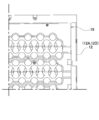
- a gap GP can be formed between the battery storage portions 13. That is, when the battery holder is configured as in the prior art, it is physically impossible to separate the battery storage parts from each other because it is necessary to join the battery storage parts for storing the unit cells. If the battery storage portion 13 is fixed to the inner surfaces of the outer case 12A and the second outer case 12B, the battery storage portion 13 can be fixed by the first outer case 12A and the second outer case 12B. It is also possible to provide a gap GP between the portions 13.
- the outer case 12 is provided with a gap GP by separating the battery storage portions 13 adjacent in the horizontal direction, and is arranged in an offset shape in the vertical direction.
- the cooling gas which cools the unit cell 11 can also be flowed in the clearance gap GP, and heat dissipation can be further improved by exchanging heat with the cooling gas for each unit cell 11.
- the unit cells are held closely together, and thus it is difficult to supply the cooling gas to the side surface of the unit cell. Further cooling from the side surface as well as the end surface of the unit cell 11 can be achieved, and more effective cooling can be expected.
- the first outer case 12A and the second outer case 12B are made of a material having excellent insulating properties. For example, it is made of resin.
- the first outer case 12 ⁇ / b> A and the second outer case 12 ⁇ / b> B contain a cylindrical battery so that the cylindrical unit cell 11 can be stored.
- a plurality of parts 13 are provided.
- the unit cell 11 has a cylindrical appearance. By making this unit cell a lithium ion secondary battery, the output with respect to volume and weight can be increased. However, lithium polymer batteries and nickel metal hydride batteries can be used instead of lithium ion batteries. Therefore, this invention does not specify a unit cell as a lithium ion battery, and can use all the batteries which can be charged as a unit cell. In the illustrated battery pack, the unit cell is a cylindrical unit cell, but a rectangular battery can be used instead. Further, the unit cell 11 is provided with a temperature sensor for temperature detection. In addition to providing a temperature sensor for each unit cell, only the unit cell at a representative position may be monitored. Here, one end of the unit cell 11 in the extending direction of the cylinder is a positive electrode, and the other end is a negative electrode. (Open frame 19)
- the first outer case 12A and the second outer case 12B are each provided with an open frame 19 on the main surface.
- the open frame 19 is provided so that the opening of the battery storage unit 13 communicates.
- the unit cells 11 stored in the respective battery storage units 13 are exposed in the outer case 12 through the open frame 19, so that the heat dissipation is improved.
- Each open frame 19 is closed by the first exterior panel 30A and the second exterior panel 30B, respectively.
- the first exterior panel 30 ⁇ / b> A and the second exterior panel 30 ⁇ / b> B have a flat plate shape and are formed to have approximately the same size as the open frame 19.
- the first exterior panel 30A and the second exterior panel 30B are made of a material having excellent thermal conductivity.
- the exterior panel 30 can be made of metal having excellent thermal conductivity.
- each open frame 19 of the outer case 12 includes the first insulating sheet 25 ⁇ / b> A and the second insulating sheet 25 ⁇ / b> B, which are insulating members having excellent thermal conductivity, and the outer panel 30 and the lead plate.
- the short circuit of the unit cell 11 can be prevented while using the metal first exterior panel 30A and the second exterior panel 30B.
- the end surface of the unit cell 11 faces the open frame 19, and heat can be efficiently radiated to the outside by the exterior panel 30 arranged on the open frame 19.
- a plurality of slits can be opened in each of the first exterior panel 30A and the second exterior panel 30B.
- the end surface of the unit cell 11 can be directly brought into contact with the outside air, and the heat dissipation is further improved. That is, the conventional unit cell surrounded by the outer case and the battery holder and difficult to dissipate to the outside can be communicated with the outside through the open frame 19 of the outer case 12 and the slit of the outer panel 30. The advantage which can improve a property is acquired.
- first exterior panel 30A and the second exterior panel 30B can each be provided with a plurality of radiating fins. Thereby, the surface area of the exterior panel 30 can be increased, and the heat dissipation effect from the side surface of the exterior case 12 can also be enhanced. (vent)
- the exterior case 12 opens the first vent 14 and the second vent 15.
- the vents are rectangular or circular, and are preferably provided on opposing surfaces of the outer case 12 respectively.
- the cooling gas can be introduced from the first vent 14, the warmed cooling gas can be discharged from the second vent 15, and the cooling gas can be efficiently flowed into the outer case 12.
- the first vent 14 and the second vent 15 are each opened in a substantially vertical direction. That is, in the posture for fixing the battery pack, the first vent hole 14 and the second vent hole 15 are opened up and down, respectively.
- the air that has moved upward due to the natural convection of heat inside the exterior case 12 is discharged from the second vent 15 that opens upward, and fresh outside air from the first vent 14 that opens downward. Can be taken in and the heat radiation can be naturally achieved.
- the first vent 14 and the second vent 15 are attached to the first exterior case 12A.
- the first vent 14 forms a rectangular lattice with a width of about 2/3 of the bottom surface of the outer case 12 to allow ventilation.
- the second vent hole 15 is opened in a circular shape on the upper surface of the outer case 12, and a cylindrical guide is formed at the edge of the opening.
- the cooling gas is sent to the second vent 15 using the heat rise on the inner surface of the outer case 12, and the cooling air can flow from the first vent 14 to the entire interior of the outer case 12.
- both may be rectangular lattices, or both may be configured to have several cylindrical vents.
- a blower fan FN may be provided in the vicinity of the first vent 14 or the second vent 15 so that the cooling gas can easily flow.
- a blower fan FN is provided in the vicinity of the second vent hole 15 opened upward, and air is flown so as to suck the blower fan FN from the discharge side.
- the present invention is not limited to this configuration, and a configuration may be adopted in which a fan is arranged on the suction side and external air is forced into the outer case 12 to flow.
- the opening surface is provided in the side surface of the exterior case 12, it is radiated from the end surface of the unit cell 11 via the exterior panel 30, while the side surface of the unit cell 11 is caused by the flow of cooling air. Heat exchange is performed, and the unit cell 11 can efficiently dissipate heat as a whole. As a result, a larger current can be passed through the unit cell 11, and the output of the battery pack can be increased. (connector)
- the battery pack 100 has a built-in protection circuit that monitors the temperature and voltage of the plurality of unit cells 11.
- the protection circuit is mounted on the battery circuit board 22. Information detected by the protection circuit is output to an external device via the connector unit 16. Further, by communicating with an external device through the connector unit 16, a signal from the external device can be received and processed on the battery pack side. For example, an abnormal signal may be detected by a battery pack and transmitted to an external device, and the external device may be instructed to stop power output.
- the input / output connection of the connector section 16 is, for example, RS-422, RS-423, RS-485, serial connection such as USB, parallel connection, or a network such as LAN, electrically, magnetically, or optically. You can connect and communicate. In the example of FIGS.
- the connector unit 16 can connect the optical fiber 102 as the cable 101.
- a method for connecting the connector portion 16 and the optical fiber 102 will be described later, but the optical fiber 102 has a gentle curve.
- the connector portion 16 is installed upward on the side surface of the battery pack 100.
- the cable 101 can be easily connected between the battery packs 100 when the battery packs 100 are stored in the rack 200 in a state of being stacked vertically and horizontally as shown in FIG. That is, when connecting the cable 101 between the battery packs 100 arranged on the left and right, it is possible to avoid a situation where the cable 101 hangs down and rubs against the lower battery pack 100 or the cable 101 connecting the lower battery packs 100.
- the connector unit 16 is fixed to the connector board 17.
- the connector portion 16 is configured such that a recess is provided on the side surface of the exterior case 12 instead of on a flat surface, and the connector portion 16 is disposed in the recess.
- the side surface of the outer case 12 is continuously inclined from the plane of the side surface from below to above. It is set as the inclined surface 24a made. Further, the connector board 17 is fixed substantially perpendicular to the inclined surface 24a so that the connector jack can be inserted and removed substantially parallel to the inclined surface 24a.
- the connector is formed along the inclined surface 24a without forcibly bending the optical fiber 102 extending from the connector jack. It can be gently bent from the portion 16 and pulled out, and damage to the optical fiber 102 can be avoided. Furthermore, the amount of protrusion of the optical fiber in the vertical direction of the side surface, that is, the direction protruding to the side surface side can be suppressed.
- the connector board 17 is held inside the outer case 12 so as not to be parallel to the side surface of the outer case 12 but in an oblique posture.
- the exterior case 12 is provided with a mounting groove 18 for holding the connector substrate 17.
- the inclined surface 24a described above can be formed by integrally molding the side surface of the outer case 12, but preferably, as shown in FIG. 3, a connector cover 24, which is a separate member from the outer case 12, is prepared.
- the connector cover 24 is provided with an inclined surface 24 a and the side surface of the battery pack 100 is covered with the connector cover 24.
- the connector cover 24 is preferably provided with an inclined surface 24a as shown in the cross-sectional view of FIG. 9, and the connector substrate 17 is arranged at the open end with the tip of the inclined surface 24a as an open end. It is preferable.
- the connector cover 24 is provided with an inclined surface 24a that is inclined upward from below the connector cover 24, and further provided with a flat portion 24b that is flush with the surface of the connector cover 24. Yes.
- the connector board 17 By disposing the connector board 17 inside the flat portion 24b, the connector is protected like a flaw by the flat portion 24b, and dust intrusion into the connector portion can be reduced.
- the exterior case 12 is arranged in the posture as shown in FIG.
- the information to the connector unit 16 is input / output from the battery circuit board 22 provided inside the side surface of the battery pack 100 as shown in the exploded perspective view of the battery pack 100 in FIG.
- the battery circuit board 22 includes a voltage detection circuit for each unit cell 11, a temperature detection circuit in the battery pack 100, and a CPU and device for controlling them.
- a configuration such as a current detection circuit, a temperature detection circuit in which each unit cell 11 or a plurality of battery elements 11 are aggregated can also be performed.
- the battery pack 100 is provided so that the connector plate 24 is attached to the insulating plate 23 that protects the battery circuit board 22 and the side surface of the battery pack 100.
- a metal such as SUS304 can be used for the connector cover 24, or a resin material can be used.
- the battery circuit board 22 is inserted into the board holder 27.
- the substrate holder 27 is formed in a bottomed box shape that is sized to allow the battery circuit board 22 to be inserted, and surrounds the battery circuit board 22 with a peripheral wall with the battery circuit board 22 inserted.
- the battery circuit board 22 is arranged at a fixed position in the outer case 12 through the board holder 27.
- the lead plates 20 ⁇ / b> A and 20 ⁇ / b> B connected to the end face of the unit cell 11 are extended and conducted to the battery circuit board 22.
- the end edges of the lead plates 20A and 20B are extended and bent, and the peripheral wall of the substrate holder 27 has a concave shape to which the bent pieces 20a of the lead plates 20A and 20B are locked. A notch is formed.
- the battery circuit board 22 has a total of 14 electrode terminals in a bent piece 20a, including 7 systems on the first exterior case 12A side by the lead plate 20A on the outer surface of the exterior case 12 and 7 systems on the second exterior case 12B side by the lead plate 20B. Connected as. Thereby, the several unit cell 11 is detected with the voltage detection circuit for every parallel circuit, and manages the voltage. Thereby, overdischarge and overcharge can be prevented.
- the electric circuit board 22 includes a circuit for determining whether the information detected by each detection circuit is in a normal operation state or an abnormal operation state by a CPU or other device and outputting the information, and from an external controller.
- a circuit for collecting information is also provided.
- connection terminal 21 as the high voltage output terminal of the battery pack has the first exterior case 12A having a convex side surface as shown in FIG.
- the second outer case 12B has a concave side surface and can be integrally coupled to the first outer case 12A, and the connection terminal 21 can be mounted in the mounting opening provided in the first outer case 12A.
- one of the positive and negative terminals of the connection terminal 21 is connected to the bus bar 26A on the outer upper surface of the first outer case 12A shown in FIG. 4 with the bus bar 26A on the inner upper surface of the outer case 12 shown in FIG. Via the fuse FU, it is connected to the bus bar 26A on the upper side surface, and its tip is connected to one terminal of the connection terminal 21.
- connection terminal 21 is connected to the bus bar 26B on the outer lower surface of the second outer case 12B shown in FIG. 3 and connected to the bus bar 26B on the lower left side surface of the outer case 12 shown in FIG.
- the tip is connected to the other terminal of the connection terminal 21. Accordingly, a high voltage in which the unit cells 11 are connected in parallel or / and in series is output to the connection terminal 21.
- connection terminal 21 and the battery circuit board 22 to which the high voltage of the battery pack 100 is applied are arranged opposite to each other, that is, away from each other, so that the influence of high frequency noise of the output current on the battery circuit board 22
- the influence of the connector unit 16 connected to the battery circuit board 22 on an external controller, another battery pack connected in series, and the like can be reduced.
- the battery pack is suitably used as a backup power supply device that can be mounted on a rack 200 such as a computer server as shown in FIG. 13, a backup power supply device for a radio base station such as a mobile phone, a power storage device combined with a solar battery, and the like. it can.
Landscapes
- Chemical & Material Sciences (AREA)
- Chemical Kinetics & Catalysis (AREA)
- Electrochemistry (AREA)
- General Chemical & Material Sciences (AREA)
- Engineering & Computer Science (AREA)
- Manufacturing & Machinery (AREA)
- Inorganic Chemistry (AREA)
- Battery Mounting, Suspending (AREA)
- Secondary Cells (AREA)
Abstract
Description
(素電池11)
(開放枠19)
(通気口)
(コネクタ)
(電池回路基板22)
(接続端子21)
11…素電池
12…外装ケース
12A…第一外装ケース
12B…第二外装ケース
13…電池収納部
14…第一通気口
15…第二通気口
16…コネクタ部
17…コネクタ基板
18…取り付け溝
19…開放枠
20A、20B、20C、20D…リード板
20a…折曲片
21…接続端子
22…電池回路基板
23…絶縁板
24…コネクタカバー
24a…傾斜面
24b…平坦部
25…絶縁シート
25A…第一絶縁シート
25B…第二絶縁シート
26A…バスバー
26B…バスバー
27…基板ホルダ
30…外装パネル
30A…第一外装パネル
30B…第二外装パネル
31…ラック固定金具
32…ヒューズカバー
101…ケーブル
102…光ファイバ
200…ラック
810…電池ブロック
811…素電池
815、816…電池ホルダ
813…電池収納部
831、832…外装ケース
840…メイン回路基板
841…発熱ブロック
842…放熱ブロック
GP…隙間
FN…送風ファン
FU…ヒューズ
Claims (7)
- 一方向に延長された外観を略円柱状とする複数の素電池(11)と、
前記複数の素電池(11)を個別に収納するための略円筒状の電池収納部(13)を複数、内面に設けた、外形を略矩形状としてなる第一外装ケース(12A)と、
複数の素電池(11)を個別に収納する電池収納部(13)を内面に設けると共に、前記第一外装ケース(12A)と接合されて、前記複数の素電池(11)を長手方向の両側から狭持するようにして保持可能な、外形を略矩形状としてなる第二外装ケース(12B)と、
を備え、
前記電池収納部(13)は、隣接する電池収納部(13)との間で隙間(GP)を設けてなることを特徴とする電池パック。 - 請求項1に記載の電池パックであって、
前記第一外装ケース(12A)及び第二外装ケース(12B)はそれぞれ、各電池収納部(13)と連通された開放枠(19)を設けており、
前記電池パックはさらに、
前記第一外装ケース(12A)及び第二外装ケース(12B)に設けられた開放枠(19)をそれぞれ閉塞するための熱伝導性を有する第一外装パネル(30A)及び第二外装パネル(30B)と、
を備えてなることを特徴とする電池パック。 - 請求項2に記載の電池パックであって、
前記第一外装パネル(30A)及び第二外装パネル(30B)は、それぞれ、複数のスリットを開口してなることを特徴とする電池パック。 - 請求項1から3のいずれか一に記載の電池パックであって、
前記第一外装ケース(12A)及び第二外装ケース(12B)の少なくともいずれかは、矩形状を構成する第一面に第一通気口(14)を、該第一面と対向する第二面に、第二通気口(15)を、それぞれ開口してなり、
前記電池パックは、前記第一通気口(14)及び第二通気口(15)とが、それぞれ略垂直方向に開口する姿勢に保持されてなることを特徴とする電池パック。 - 請求項1から4のいずれか一に記載の電池パックであって、
前記第一面と第二面が、前記開口面を設けた面と交差されてなることを特徴とする電池パック。 - 請求項1から5のいずれか一に記載の電池パックであって、
前記第一外装ケース(12A)及び第二外装ケース(12B)の少なくともいずれかは、第三面において、該第三面の表面から窪ませるように
部分的に傾斜面(24a)を備えており、
該傾斜面(24a)を設けた第三面が略鉛直面となる姿勢に、前記電池パックが保持されてなり、
さらに前記傾斜面(24a)は、前記第三面の平坦面から、上方に向かって離れる方向に傾斜されてなり、
前記傾斜面(24a)の端面に、外部機器と接続するためのコネクタ部(16)を設けてなることを特徴とする電池パック。 - 請求項1から6のいずれか一に記載の電池パックであって、
前記第一外装ケース(12A)及び第二外装ケース(12B)が樹脂製であり、
前記第一絶縁シート(25A)及び第二絶縁シート(25B)が熱伝導性が高く絶縁性の樹脂製であり、
前記第一外装パネル(30A)及び第二外装パネル(30B)が金属製であることを特徴とする電池パック。
Priority Applications (4)
| Application Number | Priority Date | Filing Date | Title |
|---|---|---|---|
| US14/008,272 US20140017531A1 (en) | 2011-03-31 | 2011-12-16 | Battery pack |
| EP11862490.7A EP2693519B1 (en) | 2011-03-31 | 2011-12-16 | Battery pack |
| JP2013507066A JP5897551B2 (ja) | 2011-03-31 | 2011-12-16 | 電池パック |
| CN201180069619.2A CN103460437B (zh) | 2011-03-31 | 2011-12-16 | 电池组 |
Applications Claiming Priority (2)
| Application Number | Priority Date | Filing Date | Title |
|---|---|---|---|
| JP2011-078170 | 2011-03-31 | ||
| JP2011078170 | 2011-03-31 |
Publications (1)
| Publication Number | Publication Date |
|---|---|
| WO2012132135A1 true WO2012132135A1 (ja) | 2012-10-04 |
Family
ID=46929932
Family Applications (1)
| Application Number | Title | Priority Date | Filing Date |
|---|---|---|---|
| PCT/JP2011/079134 WO2012132135A1 (ja) | 2011-03-31 | 2011-12-16 | 電池パック |
Country Status (5)
| Country | Link |
|---|---|
| US (1) | US20140017531A1 (ja) |
| EP (1) | EP2693519B1 (ja) |
| JP (1) | JP5897551B2 (ja) |
| CN (1) | CN103460437B (ja) |
| WO (1) | WO2012132135A1 (ja) |
Cited By (15)
| Publication number | Priority date | Publication date | Assignee | Title |
|---|---|---|---|---|
| JP2013020700A (ja) * | 2011-07-07 | 2013-01-31 | Gs Yuasa Corp | コネクタ及び電源モジュール |
| US20150010802A1 (en) * | 2013-07-04 | 2015-01-08 | Denso Corporation | Battery temperature adjustment apparatus |
| JP2015037026A (ja) * | 2013-08-12 | 2015-02-23 | 三菱重工業株式会社 | 蓄電装置 |
| JP2015062153A (ja) * | 2013-09-23 | 2015-04-02 | 株式会社デンソー | 電池パック |
| WO2015190492A1 (ja) * | 2014-06-10 | 2015-12-17 | 新神戸電機株式会社 | 蓄電セルパック |
| JP2016110926A (ja) * | 2014-12-10 | 2016-06-20 | 株式会社デンソー | 電池ユニット |
| USD783530S1 (en) | 2014-06-10 | 2017-04-11 | Hitachi Chemical Company, Ltd. | Case for electric power storage cell pack |
| WO2017169729A1 (ja) * | 2016-03-30 | 2017-10-05 | 三洋電機株式会社 | バッテリパック |
| WO2017169728A1 (ja) * | 2016-03-30 | 2017-10-05 | 三洋電機株式会社 | 電池パック |
| JP2017212064A (ja) * | 2016-05-24 | 2017-11-30 | トヨタ自動車株式会社 | 電池パック |
| WO2018003468A1 (ja) * | 2016-06-29 | 2018-01-04 | パナソニックIpマネジメント株式会社 | 電池ブロック |
| WO2019013032A1 (ja) * | 2017-07-10 | 2019-01-17 | 株式会社村田製作所 | 電池モジュール、コンテナ型蓄電システム、車両、蓄電システム、電動工具および電子機器 |
| US10446890B2 (en) | 2015-01-16 | 2019-10-15 | Murata Manufacturing Co., Ltd. | Power storage module, power storage system, electronic apparatus, electric vehicle, and power system |
| JP2022534233A (ja) * | 2019-08-30 | 2022-07-28 | エルジー エナジー ソリューション リミテッド | バッテリーラック及びそれを含む電力貯蔵装置 |
| JP2023112524A (ja) * | 2022-02-01 | 2023-08-14 | スズキ株式会社 | 電池パックの設置構造 |
Families Citing this family (15)
| Publication number | Priority date | Publication date | Assignee | Title |
|---|---|---|---|---|
| CN104280914A (zh) | 2014-10-16 | 2015-01-14 | 深圳市华星光电技术有限公司 | 一种显示面板的布线结构及显示面板 |
| EP3217449B1 (en) * | 2014-11-07 | 2018-09-26 | Sanyo Electric Co., Ltd. | Power supply device |
| KR101807350B1 (ko) * | 2014-11-19 | 2017-12-08 | 주식회사 엘지화학 | 에너지 저장 장치용 컨테이너 |
| KR102317501B1 (ko) * | 2015-04-29 | 2021-10-26 | 삼성에스디아이 주식회사 | 배터리 팩 |
| DK3449526T3 (da) | 2016-04-20 | 2022-04-19 | Corvus Energy Inc | Bagpladeanordning med strøm- og køleunderkonstruktioner |
| WO2017208736A1 (ja) * | 2016-05-30 | 2017-12-07 | パナソニックIpマネジメント株式会社 | 熱伝導シートおよびこれを用いた電池パック |
| CN105932190B (zh) * | 2016-06-27 | 2019-01-22 | 广东志成冠军集团有限公司 | 车载磷酸铁锂电池包 |
| WO2018035608A1 (en) * | 2016-08-23 | 2018-03-01 | Corvus Energy Inc. | Battery system |
| WO2018165268A1 (en) * | 2017-03-09 | 2018-09-13 | Science Applications International Corporation | Battery assembly |
| CN108574062A (zh) * | 2017-03-13 | 2018-09-25 | 珠海银隆电器有限公司 | 一种储能电池箱 |
| KR102119152B1 (ko) * | 2017-12-12 | 2020-06-04 | 삼성에스디아이 주식회사 | 배터리 팩 |
| US11949116B2 (en) * | 2019-10-30 | 2024-04-02 | Baidu Usa Llc | High power and energy density battery backup unit cell package design |
| KR20210070683A (ko) | 2019-12-05 | 2021-06-15 | 삼성에스디아이 주식회사 | 배터리 팩 |
| CN113053677B (zh) * | 2019-12-26 | 2023-12-01 | 佳能株式会社 | 电源单元和包括电源单元的放射线摄像装置 |
| CN111525210B (zh) * | 2020-04-27 | 2021-12-28 | 深圳市元鼎科技有限公司 | 户外电源 |
Citations (3)
| Publication number | Priority date | Publication date | Assignee | Title |
|---|---|---|---|---|
| JP2001060466A (ja) * | 1999-08-23 | 2001-03-06 | Japan Storage Battery Co Ltd | 組電池 |
| JP2005285456A (ja) * | 2004-03-29 | 2005-10-13 | Sanyo Electric Co Ltd | 電源装置 |
| JP2008251262A (ja) | 2007-03-29 | 2008-10-16 | Sanyo Electric Co Ltd | パック電池 |
Family Cites Families (10)
| Publication number | Priority date | Publication date | Assignee | Title |
|---|---|---|---|---|
| JP3824243B2 (ja) * | 1997-06-17 | 2006-09-20 | ヤマハ発動機株式会社 | 電動車両 |
| US6627345B1 (en) * | 1999-07-15 | 2003-09-30 | Black & Decker Inc. | Battery pack |
| US8945746B2 (en) * | 2009-08-12 | 2015-02-03 | Samsung Sdi Co., Ltd. | Battery pack with improved heat dissipation efficiency |
| CN101180749B (zh) * | 2005-05-23 | 2011-04-13 | 松下电器产业株式会社 | 电池模块及其制造方法 |
| KR100886571B1 (ko) * | 2006-08-07 | 2009-03-05 | 주식회사 엘지화학 | 전지팩 케이스 |
| JP5018204B2 (ja) * | 2007-04-19 | 2012-09-05 | パナソニック株式会社 | 蓄電ユニット |
| CN101803062B (zh) * | 2007-09-21 | 2013-11-20 | 罗伯特.博世有限公司 | 电池组 |
| JP2009176689A (ja) * | 2008-01-28 | 2009-08-06 | Sanyo Electric Co Ltd | 電池パック |
| KR101065926B1 (ko) * | 2009-07-09 | 2011-09-19 | 삼성에스디아이 주식회사 | 다수의 단위 셀을 구비하는 배터리 팩 |
| CN201655871U (zh) * | 2010-05-10 | 2010-11-24 | 林道勇 | 一种圆柱电池模块组装装置 |
-
2011
- 2011-12-16 CN CN201180069619.2A patent/CN103460437B/zh active Active
- 2011-12-16 US US14/008,272 patent/US20140017531A1/en not_active Abandoned
- 2011-12-16 JP JP2013507066A patent/JP5897551B2/ja active Active
- 2011-12-16 EP EP11862490.7A patent/EP2693519B1/en active Active
- 2011-12-16 WO PCT/JP2011/079134 patent/WO2012132135A1/ja active Application Filing
Patent Citations (3)
| Publication number | Priority date | Publication date | Assignee | Title |
|---|---|---|---|---|
| JP2001060466A (ja) * | 1999-08-23 | 2001-03-06 | Japan Storage Battery Co Ltd | 組電池 |
| JP2005285456A (ja) * | 2004-03-29 | 2005-10-13 | Sanyo Electric Co Ltd | 電源装置 |
| JP2008251262A (ja) | 2007-03-29 | 2008-10-16 | Sanyo Electric Co Ltd | パック電池 |
Non-Patent Citations (1)
| Title |
|---|
| See also references of EP2693519A4 |
Cited By (24)
| Publication number | Priority date | Publication date | Assignee | Title |
|---|---|---|---|---|
| JP2013020700A (ja) * | 2011-07-07 | 2013-01-31 | Gs Yuasa Corp | コネクタ及び電源モジュール |
| US20150010802A1 (en) * | 2013-07-04 | 2015-01-08 | Denso Corporation | Battery temperature adjustment apparatus |
| JP2015037026A (ja) * | 2013-08-12 | 2015-02-23 | 三菱重工業株式会社 | 蓄電装置 |
| JP2015062153A (ja) * | 2013-09-23 | 2015-04-02 | 株式会社デンソー | 電池パック |
| WO2015190492A1 (ja) * | 2014-06-10 | 2015-12-17 | 新神戸電機株式会社 | 蓄電セルパック |
| USD783530S1 (en) | 2014-06-10 | 2017-04-11 | Hitachi Chemical Company, Ltd. | Case for electric power storage cell pack |
| JP2016110926A (ja) * | 2014-12-10 | 2016-06-20 | 株式会社デンソー | 電池ユニット |
| US10446890B2 (en) | 2015-01-16 | 2019-10-15 | Murata Manufacturing Co., Ltd. | Power storage module, power storage system, electronic apparatus, electric vehicle, and power system |
| JPWO2017169728A1 (ja) * | 2016-03-30 | 2019-02-14 | 三洋電機株式会社 | 電池パック |
| WO2017169728A1 (ja) * | 2016-03-30 | 2017-10-05 | 三洋電機株式会社 | 電池パック |
| WO2017169729A1 (ja) * | 2016-03-30 | 2017-10-05 | 三洋電機株式会社 | バッテリパック |
| JP2017212064A (ja) * | 2016-05-24 | 2017-11-30 | トヨタ自動車株式会社 | 電池パック |
| US11398659B2 (en) | 2016-06-29 | 2022-07-26 | Panasonic Intellectual Property Management Co., Ltd. | Battery block |
| JPWO2018003468A1 (ja) * | 2016-06-29 | 2019-04-25 | パナソニックIpマネジメント株式会社 | 電池ブロック |
| US10916744B2 (en) | 2016-06-29 | 2021-02-09 | Panasonic Intellectual Property Management Co., Ltd. | Battery block |
| JP2021177499A (ja) * | 2016-06-29 | 2021-11-11 | パナソニックIpマネジメント株式会社 | 電池ブロック |
| WO2018003468A1 (ja) * | 2016-06-29 | 2018-01-04 | パナソニックIpマネジメント株式会社 | 電池ブロック |
| JP7186371B2 (ja) | 2016-06-29 | 2022-12-09 | パナソニックIpマネジメント株式会社 | 電池ブロック |
| WO2019013032A1 (ja) * | 2017-07-10 | 2019-01-17 | 株式会社村田製作所 | 電池モジュール、コンテナ型蓄電システム、車両、蓄電システム、電動工具および電子機器 |
| JPWO2019013032A1 (ja) * | 2017-07-10 | 2020-04-16 | 株式会社村田製作所 | 電池モジュール、コンテナ型蓄電システム、車両、蓄電システム、電動工具および電子機器 |
| JP2022534233A (ja) * | 2019-08-30 | 2022-07-28 | エルジー エナジー ソリューション リミテッド | バッテリーラック及びそれを含む電力貯蔵装置 |
| JP7301165B2 (ja) | 2019-08-30 | 2023-06-30 | エルジー エナジー ソリューション リミテッド | バッテリーラック及びそれを含む電力貯蔵装置 |
| JP2023112524A (ja) * | 2022-02-01 | 2023-08-14 | スズキ株式会社 | 電池パックの設置構造 |
| JP7396380B2 (ja) | 2022-02-01 | 2023-12-12 | スズキ株式会社 | 電池パックの設置構造 |
Also Published As
| Publication number | Publication date |
|---|---|
| JP5897551B2 (ja) | 2016-03-30 |
| JPWO2012132135A1 (ja) | 2014-07-24 |
| US20140017531A1 (en) | 2014-01-16 |
| EP2693519A4 (en) | 2015-04-29 |
| EP2693519A1 (en) | 2014-02-05 |
| CN103460437B (zh) | 2016-08-17 |
| CN103460437A (zh) | 2013-12-18 |
| EP2693519B1 (en) | 2016-11-23 |
Similar Documents
| Publication | Publication Date | Title |
|---|---|---|
| JP5897551B2 (ja) | 電池パック | |
| US10873114B2 (en) | Secondary battery module | |
| US11133542B2 (en) | Battery pack including heat conduction medium with louver fin shape | |
| JP5699536B2 (ja) | 電池ユニット | |
| JP5723991B2 (ja) | コンパクトな構造を有するバッテリーパック | |
| US9859533B2 (en) | Energy storage apparatus | |
| JP5478099B2 (ja) | バッテリパック | |
| JP4610362B2 (ja) | パック電池 | |
| US10115953B2 (en) | Energy storage apparatus | |
| KR101252936B1 (ko) | 배터리 팩 | |
| JP2007048750A (ja) | 電池モジュール | |
| JP2012226995A (ja) | 電池集合体 | |
| US20210143379A1 (en) | Stacked battery pack | |
| EP3952005A1 (en) | Battery module and battery pack including same | |
| CN114556675A (zh) | 电池模块和包括该电池模块的电池组 | |
| KR102480098B1 (ko) | 이차 전지 모듈 | |
| JP5944481B2 (ja) | 電源装置 | |
| KR20210042583A (ko) | 전지 모듈 및 이를 포함하는 전지팩 | |
| JP2013105723A (ja) | 蓄電装置 | |
| KR20130007864A (ko) | 전지모듈 케이스 | |
| KR20220049190A (ko) | 전지 모듈 및 그 제조 방법 | |
| KR101586641B1 (ko) | 전지팩 모듈 하우징 | |
| JP2014002959A (ja) | 蓄電モジュール | |
| JP2022547926A (ja) | 電池モジュールおよびその製造方法 | |
| KR20230097897A (ko) | 로지컬 셀, 이차전지 모듈 및 이를 포함하는 이차전지 팩 |
Legal Events
| Date | Code | Title | Description |
|---|---|---|---|
| 121 | Ep: the epo has been informed by wipo that ep was designated in this application |
Ref document number: 11862490 Country of ref document: EP Kind code of ref document: A1 |
|
| ENP | Entry into the national phase |
Ref document number: 2013507066 Country of ref document: JP Kind code of ref document: A |
|
| WWE | Wipo information: entry into national phase |
Ref document number: 14008272 Country of ref document: US |
|
| NENP | Non-entry into the national phase |
Ref country code: DE |
|
| REEP | Request for entry into the european phase |
Ref document number: 2011862490 Country of ref document: EP |
|
| WWE | Wipo information: entry into national phase |
Ref document number: 2011862490 Country of ref document: EP |