WO2012132047A1 - エジェクタ - Google Patents
エジェクタ Download PDFInfo
- Publication number
- WO2012132047A1 WO2012132047A1 PCT/JP2011/069464 JP2011069464W WO2012132047A1 WO 2012132047 A1 WO2012132047 A1 WO 2012132047A1 JP 2011069464 W JP2011069464 W JP 2011069464W WO 2012132047 A1 WO2012132047 A1 WO 2012132047A1
- Authority
- WO
- WIPO (PCT)
- Prior art keywords
- ejector
- air
- nozzle
- port
- inner diameter
- Prior art date
Links
Images


Classifications
-
- F—MECHANICAL ENGINEERING; LIGHTING; HEATING; WEAPONS; BLASTING
- F04—POSITIVE - DISPLACEMENT MACHINES FOR LIQUIDS; PUMPS FOR LIQUIDS OR ELASTIC FLUIDS
- F04F—PUMPING OF FLUID BY DIRECT CONTACT OF ANOTHER FLUID OR BY USING INERTIA OF FLUID TO BE PUMPED; SIPHONS
- F04F5/00—Jet pumps, i.e. devices in which flow is induced by pressure drop caused by velocity of another fluid flow
- F04F5/14—Jet pumps, i.e. devices in which flow is induced by pressure drop caused by velocity of another fluid flow the inducing fluid being elastic fluid
-
- F—MECHANICAL ENGINEERING; LIGHTING; HEATING; WEAPONS; BLASTING
- F04—POSITIVE - DISPLACEMENT MACHINES FOR LIQUIDS; PUMPS FOR LIQUIDS OR ELASTIC FLUIDS
- F04B—POSITIVE-DISPLACEMENT MACHINES FOR LIQUIDS; PUMPS
- F04B39/00—Component parts, details, or accessories, of pumps or pumping systems specially adapted for elastic fluids, not otherwise provided for in, or of interest apart from, groups F04B25/00 - F04B37/00
- F04B39/0027—Pulsation and noise damping means
- F04B39/0055—Pulsation and noise damping means with a special shape of fluid passage, e.g. bends, throttles, diameter changes, pipes
- F04B39/0061—Pulsation and noise damping means with a special shape of fluid passage, e.g. bends, throttles, diameter changes, pipes using muffler volumes
-
- F—MECHANICAL ENGINEERING; LIGHTING; HEATING; WEAPONS; BLASTING
- F01—MACHINES OR ENGINES IN GENERAL; ENGINE PLANTS IN GENERAL; STEAM ENGINES
- F01N—GAS-FLOW SILENCERS OR EXHAUST APPARATUS FOR MACHINES OR ENGINES IN GENERAL; GAS-FLOW SILENCERS OR EXHAUST APPARATUS FOR INTERNAL COMBUSTION ENGINES
- F01N1/00—Silencing apparatus characterised by method of silencing
- F01N1/003—Silencing apparatus characterised by method of silencing by using dead chambers communicating with gas flow passages
-
- F—MECHANICAL ENGINEERING; LIGHTING; HEATING; WEAPONS; BLASTING
- F04—POSITIVE - DISPLACEMENT MACHINES FOR LIQUIDS; PUMPS FOR LIQUIDS OR ELASTIC FLUIDS
- F04F—PUMPING OF FLUID BY DIRECT CONTACT OF ANOTHER FLUID OR BY USING INERTIA OF FLUID TO BE PUMPED; SIPHONS
- F04F5/00—Jet pumps, i.e. devices in which flow is induced by pressure drop caused by velocity of another fluid flow
- F04F5/14—Jet pumps, i.e. devices in which flow is induced by pressure drop caused by velocity of another fluid flow the inducing fluid being elastic fluid
- F04F5/16—Jet pumps, i.e. devices in which flow is induced by pressure drop caused by velocity of another fluid flow the inducing fluid being elastic fluid displacing elastic fluids
- F04F5/18—Jet pumps, i.e. devices in which flow is induced by pressure drop caused by velocity of another fluid flow the inducing fluid being elastic fluid displacing elastic fluids for compressing
-
- F—MECHANICAL ENGINEERING; LIGHTING; HEATING; WEAPONS; BLASTING
- F04—POSITIVE - DISPLACEMENT MACHINES FOR LIQUIDS; PUMPS FOR LIQUIDS OR ELASTIC FLUIDS
- F04F—PUMPING OF FLUID BY DIRECT CONTACT OF ANOTHER FLUID OR BY USING INERTIA OF FLUID TO BE PUMPED; SIPHONS
- F04F5/00—Jet pumps, i.e. devices in which flow is induced by pressure drop caused by velocity of another fluid flow
- F04F5/14—Jet pumps, i.e. devices in which flow is induced by pressure drop caused by velocity of another fluid flow the inducing fluid being elastic fluid
- F04F5/16—Jet pumps, i.e. devices in which flow is induced by pressure drop caused by velocity of another fluid flow the inducing fluid being elastic fluid displacing elastic fluids
- F04F5/20—Jet pumps, i.e. devices in which flow is induced by pressure drop caused by velocity of another fluid flow the inducing fluid being elastic fluid displacing elastic fluids for evacuating
-
- F—MECHANICAL ENGINEERING; LIGHTING; HEATING; WEAPONS; BLASTING
- F04—POSITIVE - DISPLACEMENT MACHINES FOR LIQUIDS; PUMPS FOR LIQUIDS OR ELASTIC FLUIDS
- F04F—PUMPING OF FLUID BY DIRECT CONTACT OF ANOTHER FLUID OR BY USING INERTIA OF FLUID TO BE PUMPED; SIPHONS
- F04F5/00—Jet pumps, i.e. devices in which flow is induced by pressure drop caused by velocity of another fluid flow
- F04F5/44—Component parts, details, or accessories not provided for in, or of interest apart from, groups F04F5/02 - F04F5/42
- F04F5/46—Arrangements of nozzles
Definitions
- the present invention relates to an ejector that generates a negative pressure in a suction port by blowing compressed air from a nozzle to a diffuser and ejecting the compressed air from an ejection port of the diffuser, and more particularly to reduce exhaust noise ejected from the ejection port
- This relates to an ejector equipped with a muffler.
- the vacuum generator that uses the flow of compressed air to generate a negative pressure is called an ejector.
- This ejector has a nozzle that squeezes compressed air and then diffuses and ejects it, and a diffuser that is coaxial with the nozzle.
- a negative pressure region is formed around the tip of the nozzle.
- the suction port is opened in this negative pressure region, the suction port portion becomes negative pressure due to the viscosity of air.
- Patent Document 2 there is a type incorporated in a block as an ejector used for sucking and transporting a small electronic component such as a semiconductor chip of several millimeters square.
- This type of ejector consists of a vacuum generating solenoid valve that controls the supply of compressed air to the ejector nozzle, and a vacuum breaking solenoid valve that controls the supply of compressed air for vacuum breaking when removing electronic components from the suction tool. Is assembled to the block.
- Both types of ejectors are provided with a muffler in order to reduce exhaust noise caused by air discharged from the diffuser jet port, that is, the exhaust port.
- the total exhaust noise ejected from the plurality of ejection ports is larger than the exhaust noise from one ejector.
- the exhaust port formed in the most downstream part of the exhaust flow path is closed by a silencing member made of a porous member, and exhaust air is blocked.
- a type in which ventilation resistance is added before discharging to the outside is often used.
- the degree of vacuum of the negative pressure air and the suction flow rate cannot be secured sufficiently, so in the method of adding ventilation resistance to the exhaust air, In order to secure the degree of vacuum and the suction flow rate, there was a limit to enhancing the silencing effect.
- Increasing the ventilation resistance of the exhaust flow path by disposing a silencer member at the exhaust port so as to block the flow of air exhausted from the ejection port will reduce the vacuum degree of negative pressure air and the suction flow rate. It is.
- An object of the present invention is to reduce exhaust noise from the ejector while maintaining the vacuum degree and suction flow rate of the negative pressure air by the ejector.
- the ejector according to the present invention includes an ejector block in which an air supply port communicates with a base end and an ejector block formed on the base end side of the ejector storage hole and throttles compressed air from the air supply port.
- a nozzle that is diffused and ejected, and an ejecting port that is disposed in the ejector receiving hole at a position downstream of the nozzle and that ejects air ejected from the nozzle and air that has flowed in from the suction port is formed, and
- a diffuser that forms an ejector together with a nozzle, a cylindrical portion that covers the ejection port, and a distal end wall portion that is integrated with the distal end of the cylindrical portion, and a silencer chamber into which air discharged from the ejection port flows is provided.
- the ejector according to the present invention is characterized in that a silencing gap is formed between the silencing member and the inner peripheral surface of the cylindrical portion.
- the ejector according to the present invention is characterized in that an inner diameter of the nozzle is 0.5 to 1.0 mm and a length of the silencer member is 20 to 50 mm.
- the ejector according to the present invention is characterized in that the inner diameter of the nozzle is 0.5 to 1.0 mm, and the inner diameter of the exhaust port is 2 to 4 times the inner diameter of the nozzle.
- the air ejected from the ejector port of the diffuser in the ejector flows downstream while expanding radially outward, and the diffused air that is the main element of noise generation is a cylindrical silencer It is silenced by the member.
- the flow of the central part of the exhaust jet with few noise generating elements is discharged to the outside from the exhaust port, and the vacuum level and suction flow rate of the negative pressure air generated by discharging the central air flow from the exhaust port And can be secured sufficiently.
- the exhaust noise from an ejector can be reduced, maintaining the vacuum degree and suction flow rate of the negative pressure air by an ejector.
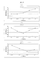
- FIG. (A) to (C) are characteristic diagrams showing the measurement results of the relationship between the supply pressure and the degree of vacuum when the length of the silencer member is different for the 05 type, 07 type and 10 type. It is. (A) to (C) are characteristic diagrams showing the measurement results of the relationship between the supply pressure and the suction flow rate when the lengths of the silencer members are made different for the three types.
- (A) to (C) are characteristic diagrams showing the relationship between the length of the muffler member and the noise performance for three types.
- (A) to (C) are characteristic diagrams showing the measurement results of the relationship between the supply pressure and the degree of vacuum when the inner diameters of the exhaust ports are made different for the three types.
- (A) to (C) are characteristic diagrams showing the measurement results of the relationship between the supply pressure and the suction flow rate when the inner diameters of the exhaust ports are made different for the three types.
- (A) to (C) are characteristic diagrams showing the measurement results of the relationship between the inner diameter of the exhaust port and the noise performance for three types.
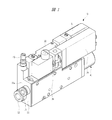
- the ejector 10 has a rectangular parallelepiped ejector block 11.
- a positive pressure joint 12 and a negative pressure joint 13 are attached to one end face 11 a of the ejector block 11.
- a positive pressure pipe 14 is detachably attached to the positive pressure joint 12, and the ejector 10 is connected to an air pressure supply source 15 having a compressor and the like by the positive pressure pipe 14.
- a negative pressure pipe 16 is detachably attached to the negative pressure joint 13, and an adsorption tool 17 as a negative pressure operating device for adsorbing electronic components is attached to the negative pressure pipe 16.
- the positive pressure pipe 14 and the negative pressure pipe 16 are each formed of a member in which a flow path for guiding air is formed, such as a flexible tube and a rigid pipe.
- an ejector receiving hole 18 is formed in the ejector block 11. As shown in FIGS. 2 and 3, the ejector receiving hole 18 is open to the other end surface 11 b of the ejector block 11 and is a bottomed hole having a bottom. An ejector 20 is incorporated in the ejector accommodation hole 18.
- the ejector 20 has a nozzle 21 disposed on the bottom side of the ejector receiving hole and a diffuser 22 disposed on the opening end side of the nozzle 21.
- the nozzle 21 has a base portion 21a fitted in the ejector receiving hole 18 and a tip portion 21b having a smaller diameter.
- An inflow hole 24 communicating with an air supply port 23 formed in the bottom surface of the ejector accommodating hole 18 is formed in the base portion 21a, and a throttle hole 25 having a smaller diameter than the inflow hole 24 flows into the distal end portion 21b.
- a diffusion hole 26 is formed which communicates with the hole 24 and communicates with the throttle hole 25 and has an inner diameter gradually increasing toward the distal end surface on the distal end side.
- the diffuser 22 has a suction portion 22a on the proximal end side that is fitted to the outside of the distal end portion 21b of the nozzle 21 and an ejection portion 22b on the distal end side.
- a guide hole 27 through which compressed air flows from the diffusion hole 26 of the nozzle 21 and a diffusion hole 28 having an inner diameter gradually increasing toward the tip surface are formed in the ejection portion 22b.
- the opening of the diffusion hole 28 serves as an ejection port 29 for discharging air.
- a suction port 30 communicating with the suction space between the tip of the nozzle 21 and the guide hole 27 of the diffuser 22 is formed in the suction portion 22 a of the diffuser 22.
- the suction port 30 is communicated with the negative pressure joint 13.
- the compressed air from the air pressure supply source 15 When the compressed air from the air pressure supply source 15 is supplied to the air supply port 23, the compressed air passes through the throttle hole 25 of the nozzle 21 and is injected from the diffusion hole 26 toward the guide hole 27 of the diffuser 22.
- the air injected from the diffusion hole 26 entrains the air between the diffusion hole 26 and the guide hole 27, that is, the air in the suction port 30, and is ejected from the diffusion hole 28 of the diffuser 22 together with the entrained air.
- negative pressure air is supplied from the suction port 30 to the suction tool 17 connected by the negative pressure pipe 16, and an electronic component such as a semiconductor chip can be sucked and transported by the suction tool 17.
- a solenoid valve block 31 and a joint block 32 are attached to the upper surface of the ejector block 11.
- the electromagnetic valve block 31 is a tandem 3-port valve, and two 3-port valves are provided.
- one three-port valve constitutes a vacuum generation control valve 34 that opens and closes a vacuum generation flow path 33 between the positive pressure joint 12 and the air supply port 23.
- the other three-port valve constitutes a vacuum break control valve 37 that opens and closes a vacuum break flow path 36 between the vacuum flow path 35 formed between the suction port 30 and the negative pressure joint 13 and the positive pressure joint 12. .
- a filter 38 is provided on the upper surface of the ejector block 11 in order to remove foreign substances in the air that flow inside the negative pressure pipe 16 and travel toward the suction port 30.
- a pressure sensor 39 is provided on the upper surface of the ejector block 11 in order to detect the degree of vacuum of the vacuum channel 35.
- a throttle 40 is attached to the upper surface of the ejector block 11 in order to adjust the flow rate of the compressed air for vacuum break supplied to the adsorber 17 by the vacuum break channel 36.
- a muffler 41 is attached to the end surface 11b of the ejector block 11 in order to reduce exhaust noise due to the air flow ejected from the ejection port 29 of the ejector 20.
- the muffler 41 has a muffler main body 42 including a cylindrical portion 42a attached to the end surface 11b of the ejector block 11 with a screw or the like, and a tip wall portion 42b integrated with the tip of the cylindrical portion 42a.
- a muffler chamber 43 is formed inside the muffler main body 42.
- the tip of the diffuser 22 protrudes into the muffler main body 42, and a cylindrical holder 44 is attached to the tip of the diffuser 22.
- a cylindrical silencing member 45 is disposed inside the muffler main body 42. One end of the silencing member 45 is supported by the holder 44, and the other end is formed on a projection 46 provided on the tip wall 42b. It is supported.
- the silencing member 45 is formed of a material having air permeability such as a porous material or a fibrous material.
- a silencing gap 47 is provided between the silencing member 45 and the cylindrical portion 42 a, and exhaust noise that has passed through the silencing member 45 is silenced in the silencing gap 47.
- An exhaust port 48 is formed in the tip wall portion 42 b so as to face the ejection port 29 and be coaxial with the ejection port 29.
- the axial airflow in the center of the air jetted from the jet port 29 of the diffuser 22 into the sound deadening chamber 43 is directly discharged from the exhaust port 48 to the outside.
- the diffused airflow that flows into the silencer chamber 43 from the ejection port 29 and diffuses outward in the radial direction collides with the silencer 45 and is absorbed by the silencer 45.
- the noise of the diffused airflow that has passed through the silencing member 45 is silenced by the silencing gap 47.
- the ejector 10 for supplying negative pressure air to the negative pressure operating device such as the suction tool 17 sucks the negative pressure air having a degree of vacuum and a flow rate necessary for suction in order to suck the electronic component by the suction tool 17. It is necessary to supply the tool 17.
- the ejector 10 preferably has not only a desired degree of vacuum and a suction flow rate, but also low exhaust noise due to air ejected from the ejection port of the diffuser 22.
- a sound deadening member is embedded in an exhaust passage that guides the air ejected from the diffuser to the exhaust port.
- the inner diameter D of the exhaust port 48 also has a great influence on the degree of vacuum and flow rate of the generated negative pressure air. If the inner diameter D of the exhaust port 48 is made too small, a desired degree of vacuum is obtained. And it becomes impossible to secure the flow rate.
- the flow rate of the negative pressure air supplied to the adsorber 17 greatly depends on the nozzle diameter d set by the inner diameter of the throttle hole 25 of the nozzle 21. is doing. If the nozzle diameter d is in the range of about 0.5 to 1.0 mm, it is possible to secure a sufficient flow rate for the negative pressure air supplied to the negative pressure operating equipment used in the assembly production line for electronic components. it can.
- the vacuum degree, the suction flow rate, and the sound absorption performance of the negative pressure air were measured.
- An ejector having a nozzle diameter d of 0.5 mm is said to be of type 05
- an ejector having a nozzle diameter of 0.7 mm is said to be of type 07
- an ejector having a nozzle diameter d of 1.0 mm is said to be of type 10.
- 5A to 5C show the measurement results of the relationship between the supply pressure and the degree of vacuum when the length dimension L of the silencer 45 is different for the 05 type, 07 type and 10 type. Show.
- the inner diameter D of the exhaust port 48 of the ejector 10 used for the measurement is 3 mm.
- the supply pressure is the pressure of the compressed air supplied to the supply port 23, and the degree of vacuum is the pressure of the negative pressure air obtained by the ejector.
- the length dimension L of the sound deadening member 45 eight types of 11 mm, 16 mm, 21 mm, 26 mm, 31 mm, 36 mm, 41 mm, and 46 mm were measured.
- 5A and 5B the relationship between the supply pressure and the degree of vacuum in the above-described eight types of ejectors having different lengths is the same as illustrated. Changed. For the 10 types, a slight difference was recognized, and even when the length L was varied, there was not much difference in the degree of vacuum.
- 5A and 5B show the measurement results when the length dimension L is 11 mm, respectively.
- FIG. 5C the case where the length dimension L is 16 mm is shown by a solid line.
- a case where L is 41 mm is indicated by a one-dot chain line.
- FIGS. 6A and 6B show measurement results of the relationship between the supply pressure and the suction flow rate when the length dimension L of the silencer 45 is made different for the three types described above.
- the inner diameter D of the exhaust port 48 of the ejector 10 used for the measurement is 3 mm.
- the suction flow rate is a flow rate of air sucked into the suction tool 17 by the negative pressure obtained by the ejector 10.
- the measurement results of an ejector with an L dimension of 11 mm with the dimension L being the shortest in FIGS. 6A and 6B are shown, but there is no significant change in the suction flow rate even with other lengths. It was.
- 10 types in FIG.
- the suction flow rate was between.
- FIGS. 7A to 7C show the relationship between the length L of the muffling member 45 and the noise performance for the three types described above.
- the inner diameter D of the exhaust port 48 of the ejector 10 used for this measurement is 3 mm as in the case shown in FIGS.
- the above-described eight types are denoted by reference numerals 1 to 8, and the ejector dimension L indicated by reference numeral 1 is 11 mm, and the ejector dimensions L of 2 to 8 are sequentially 16, 21, 26. , 31, 36, 41, 46 mm.
- the noise reduction performance is improved by increasing the dimension L.
- the dimension L is set to 50 mm or more, the ejector 10 is enlarged, and the dimension L is a length in the range of 20 to 50 mm.
- the silencing performance it is possible to ensure the silencing performance for all three types.
- FIGS. 7A and 7B it has been found that for the 05 type and 07 type, when the dimension L is increased from 21 mm to 36 mm, the reduction rate of the noise is large, and the dimension L is 20 to 50 mm.
- the dimension L is set in the range of 40 to 50 mm, the silencing effect can be further enhanced.
- the sound absorbing performance can be improved if the length dimension L of the muffling member 45 is large, but if it is excessively long, the ejector 10 will be enlarged. Therefore, for the three types described above, it was found that if the length dimension L is set in the range of 20 to 50 mm, the desired noise reduction performance can be secured, and if the length dimension L is set in the range of 40 to 50 mm, the noise reduction effect can be further enhanced. . In addition, it has been found that the length dimension L of the sound deadening member 45 does not significantly affect the degree of vacuum and the suction flow rate.
- 8A to 8C show the measurement results of the relationship between the supply pressure and the degree of vacuum when the inner diameter D of the exhaust port 48 is made different for the three types described above. This measurement was performed for five types of inner diameter D, ⁇ 1, ⁇ 1.5, ⁇ 2, ⁇ 2.5, and ⁇ 3, respectively.
- 8A shows the measurement results for ⁇ 1 and ⁇ 3, and
- FIG. 8B shows the measurement results for ⁇ 1, ⁇ 1.5, and ⁇ 3.
- FIG. 8C shows the measurement results for ⁇ 1.5, ⁇ 2, ⁇ 2.5, and ⁇ 3.
- the inner diameter D is set to 1 mm or more for the 05 type, the inner diameter D is set to 1.5 mm or more for the 07 type, and the inner diameter D is set to 2 mm or more for the 10 type, the negative pressure vacuum obtained by the ejector is obtained.
- the degree was found to be sufficient. That is, it has been found that if the inner diameter D is set to be twice or more than the nozzle inner diameter d, a necessary degree of vacuum can be obtained.
- FIGS. 9A to 9C show the measurement results of the relationship between the supply pressure and the suction flow rate when the inner diameter D of the exhaust port 48 is made different for the above-described three types. Similar to the measurement result shown in FIG. 8, this measurement was performed for five types of inner diameter D, ⁇ 1, ⁇ 1.5, ⁇ 2, ⁇ 2.5, and ⁇ 3, respectively. As shown in FIG. 9C, for the 10 types, when the inner diameter D was 1 mm, the suction flow rate was insufficient, but sufficient suction flow rates were obtained with other inner diameters. For the 05 type and 07 type, the inner diameter D was sufficient.
- the inner diameter D of the exhaust port 48 is twice or more the nozzle inner diameter d in order to secure the degree of vacuum and the suction flow rate.
- FIGS. 10A to 10C show the measurement results of the relationship between the inner diameter D of the exhaust port 48 and the noise performance for the three types described above. From this measurement, as shown in FIG. 10 (A), it was found that a sufficient silencing effect can be obtained when the inner diameter D of the 05 type is 2.5 mm or less, that is, 5 times or less of the nozzle inner diameter d. As shown in FIG. 10B, for the 07 type, if the inner diameter D is in the range of 1.5 mm to 2.5 mm, that is, in the range of about 2 to 4 times the nozzle inner diameter d, a sufficient silencing effect can be obtained. It has been found. As shown in FIG. 10C, for the 10 types, if the inner diameter D is in the range of 2.0 to 3.0 mm, that is, about 2 to 3 times the nozzle inner diameter d, a sufficient silencing effect can be obtained. found.
- the present invention is not limited to the embodiment described above, and various modifications can be made without departing from the scope of the invention.
- the nozzle inner diameter is not limited to the three types described above, and various nozzle diameters can be used.
- the ejector block 11 is provided with the electromagnetic valve block 31, the filter 38, and the like, but these members may be arranged separately from the ejector block 11.
- the ejector of the present invention is applied to an apparatus for sucking and transporting a small electronic component.
Landscapes
- Engineering & Computer Science (AREA)
- Mechanical Engineering (AREA)
- General Engineering & Computer Science (AREA)
- Physics & Mathematics (AREA)
- Fluid Mechanics (AREA)
- Chemical & Material Sciences (AREA)
- Combustion & Propulsion (AREA)
- Jet Pumps And Other Pumps (AREA)
Abstract
Description
Claims (4)
- 基端に給気ポートが連通するエジェクタ収容孔が形成されたエジェクタブロックと、
前記エジェクタ収容孔の基端部側に配置され前記給気ポートからの圧縮空気を絞った後に拡散して噴出するノズルと、
前記エジェクタ収容孔に前記ノズルの下流側に位置させて配置され、前記ノズルから噴出された空気と吸引ポートから流入した空気とを吐出する噴出ポートが形成されて前記ノズルとともにエジェクタを構成するディフューザと、
前記噴出ポートを覆う円筒部および当該円筒部の先端に一体となった先端壁部を有し、内部に前記噴出ポートから吐出された空気が流入する消音室が形成されたマフラ本体と、
前記円筒部内に配置される円筒形状の消音部材と、
前記噴出ポートに対向させて前記先端壁部に前記エジェクタと同軸に設けられる排気口とを有することを特徴とするエジェクタ。 - 請求項1記載のエジェクタにおいて、前記消音部材と前記円筒部の内周面との間に消音隙間を形成することを特徴とするエジェクタ。
- 請求項1または2記載のエジェクタにおいて、前記ノズルの内径を0.5~1.0mmとし、前記消音部材の長さを20~50mmとすることを特徴とするエジェクタ。
- 請求項1~3のいずれか1項記載のエジェクタにおいて、前記ノズルの内径を0.5~1.0mmとし、前記排気口の内径を前記ノズル内径の2~4倍とすることを特徴とするエジェクタ。
Priority Applications (4)
| Application Number | Priority Date | Filing Date | Title |
|---|---|---|---|
| KR1020167020147A KR101678026B1 (ko) | 2011-03-28 | 2011-08-29 | 이젝터 |
| KR1020137025548A KR20140020944A (ko) | 2011-03-28 | 2011-08-29 | 이젝터 |
| CN201180069685.XA CN103459855B (zh) | 2011-03-28 | 2011-08-29 | 排出器 |
| US14/007,799 US9322308B2 (en) | 2011-03-28 | 2011-08-29 | Ejector |
Applications Claiming Priority (2)
| Application Number | Priority Date | Filing Date | Title |
|---|---|---|---|
| JP2011069125 | 2011-03-28 | ||
| JP2011-069125 | 2011-03-28 |
Publications (1)
| Publication Number | Publication Date |
|---|---|
| WO2012132047A1 true WO2012132047A1 (ja) | 2012-10-04 |
Family
ID=46929858
Family Applications (1)
| Application Number | Title | Priority Date | Filing Date |
|---|---|---|---|
| PCT/JP2011/069464 WO2012132047A1 (ja) | 2011-03-28 | 2011-08-29 | エジェクタ |
Country Status (6)
| Country | Link |
|---|---|
| US (1) | US9322308B2 (ja) |
| JP (1) | JP5981174B2 (ja) |
| KR (2) | KR101678026B1 (ja) |
| CN (1) | CN103459855B (ja) |
| TW (1) | TWI545266B (ja) |
| WO (1) | WO2012132047A1 (ja) |
Cited By (3)
| Publication number | Priority date | Publication date | Assignee | Title |
|---|---|---|---|---|
| JP6088719B1 (ja) * | 2015-09-17 | 2017-03-01 | 株式会社テイエルブイ | エゼクタ及びそれを備えた真空発生装置 |
| WO2017047387A1 (ja) * | 2015-09-17 | 2017-03-23 | 株式会社テイエルブイ | エゼクタ及びそれを備えた真空発生装置 |
| CN115234524A (zh) * | 2022-07-03 | 2022-10-25 | 中国船舶重工集团公司第七0三研究所 | 一种可拆卸式低噪声蒸汽喷射压缩器 |
Families Citing this family (17)
| Publication number | Priority date | Publication date | Assignee | Title |
|---|---|---|---|---|
| JP5625600B2 (ja) * | 2010-08-05 | 2014-11-19 | 株式会社サタケ | 色彩選別機のエジェクターシステム |
| JP6575013B2 (ja) | 2012-12-21 | 2019-09-18 | ピアブ・アクチエボラグ | 楕円形の末広がりセクションを有する真空エジェクタノズル |
| GB2509182A (en) | 2012-12-21 | 2014-06-25 | Xerex Ab | Vacuum ejector with multi-nozzle drive stage and booster |
| GB2509183A (en) | 2012-12-21 | 2014-06-25 | Xerex Ab | Vacuum ejector with tripped diverging exit flow nozzle |
| GB2509184A (en) | 2012-12-21 | 2014-06-25 | Xerex Ab | Multi-stage vacuum ejector with moulded nozzle having integral valve elements |
| GB201418117D0 (en) | 2014-10-13 | 2014-11-26 | Xerex Ab | Handling device for foodstuff |
| WO2016103035A2 (en) | 2014-12-22 | 2016-06-30 | Smith & Nephew Plc | Negative pressure wound therapy apparatus and methods |
| GB2557504B (en) * | 2015-10-14 | 2021-04-21 | Halliburton Energy Services Inc | Downhole valve assembly and method of using same |
| EP3163093B1 (en) * | 2015-10-30 | 2020-06-17 | Piab Aktiebolag | High vacuum ejector |
| KR101699721B1 (ko) * | 2016-09-01 | 2017-02-13 | (주)브이텍 | 진공 펌프 및 그 어레이 |
| JP6819867B2 (ja) * | 2017-02-16 | 2021-01-27 | Smc株式会社 | 電磁弁用マニホールドベース及びそれを用いた電磁弁集合体 |
| JP6767711B2 (ja) * | 2017-06-09 | 2020-10-14 | Smc株式会社 | サイレンサおよびサイレンサを用いたエジェクタ |
| JP6960582B2 (ja) * | 2017-10-19 | 2021-11-05 | Smc株式会社 | イオナイザ |
| CN109277223A (zh) * | 2018-11-19 | 2019-01-29 | 吴忠飞 | 一种真空引射器 |
| CN111765130A (zh) * | 2019-04-02 | 2020-10-13 | 台湾气立股份有限公司 | 大容量真空控制装置 |
| CN111779717A (zh) * | 2019-04-03 | 2020-10-16 | 台湾气立股份有限公司 | 具扩充功能的大容量真空控制装置 |
| US20230304510A1 (en) * | 2022-03-25 | 2023-09-28 | Guardair Corp. | Multistage vacuum |
Citations (5)
| Publication number | Priority date | Publication date | Assignee | Title |
|---|---|---|---|---|
| JPH09317698A (ja) * | 1996-05-23 | 1997-12-09 | Nippon Pisuko:Kk | 真空発生器 |
| JP2003035300A (ja) * | 2001-07-24 | 2003-02-07 | Ckd Corp | モジュール構造のエジェクタ |
| JP2003194000A (ja) * | 2001-12-25 | 2003-07-09 | Ckd Corp | エジェクタ |
| JP2003222100A (ja) * | 2003-02-05 | 2003-08-08 | Nippon Pisuko:Kk | 真空発生器 |
| US20100207409A1 (en) * | 2005-07-11 | 2010-08-19 | Delaware Capital Formation, Inc. | Auto-Release Vacuum Device |
Family Cites Families (21)
| Publication number | Priority date | Publication date | Assignee | Title |
|---|---|---|---|---|
| US3892168A (en) * | 1974-01-14 | 1975-07-01 | Molins Machine Co Inc | Counter ejector |
| JPS59160900U (ja) * | 1983-04-15 | 1984-10-27 | 株式会社 妙徳 | 真空発生装置 |
| JPS60212607A (ja) * | 1984-04-06 | 1985-10-24 | Sankei Giken Kogyo Kk | 消音器の吸音材保持構造 |
| JPS6140500A (ja) * | 1984-08-01 | 1986-02-26 | Oskar Shoji:Kk | 真空発生装置 |
| JPS6297299U (ja) * | 1985-12-09 | 1987-06-20 | ||
| JPH0823287B2 (ja) * | 1986-04-14 | 1996-03-06 | ヤマハ発動機株式会社 | 排気消音器 |
| GB8619277D0 (en) * | 1986-08-07 | 1986-09-17 | Cranfield Inst Of Tech | Jet pump |
| JPS63183300A (ja) * | 1987-01-23 | 1988-07-28 | Koganei Seisakusho:Kk | エゼクタ装置 |
| JPH0353040Y2 (ja) * | 1987-05-30 | 1991-11-19 | ||
| US5683227A (en) * | 1993-03-31 | 1997-11-04 | Smc Corporation | Multistage ejector assembly |
| US5929396A (en) * | 1997-07-29 | 1999-07-27 | Awad; Elias A. | Noise reducing diffuser |
| DE19817249C1 (de) * | 1998-04-18 | 1999-08-26 | Schmalz J Gmbh | Ejektor |
| US6364054B1 (en) * | 2000-01-27 | 2002-04-02 | Midas International Corporation | High performance muffler |
| JP2003019400A (ja) | 2001-07-11 | 2003-01-21 | Yasunari Okada | アイロン台 |
| JP2003120530A (ja) * | 2001-10-17 | 2003-04-23 | Osaka Gas Co Ltd | パージガス用消音装置 |
| JP2005262351A (ja) | 2004-03-17 | 2005-09-29 | Koganei Corp | 真空吸着ユニット |
| DE102006013970B4 (de) * | 2006-03-15 | 2008-08-14 | J. Schmalz Gmbh | Unterdruckflächengreifvorrichtung |
| SE530787C2 (sv) * | 2007-01-16 | 2008-09-09 | Xerex Ab | Ejektoranordning med luftningsfunktion |
| CN201184754Y (zh) * | 2007-12-19 | 2009-01-21 | 唐英凯 | 一种消除噪音和振动的混合换热器 |
| WO2009081467A1 (ja) * | 2007-12-21 | 2009-07-02 | Koganei Corporation | 真空発生装置 |
| JP5260354B2 (ja) * | 2009-03-03 | 2013-08-14 | 株式会社コガネイ | 真空発生装置 |
-
2011
- 2011-08-29 CN CN201180069685.XA patent/CN103459855B/zh not_active Expired - Fee Related
- 2011-08-29 KR KR1020167020147A patent/KR101678026B1/ko active IP Right Grant
- 2011-08-29 KR KR1020137025548A patent/KR20140020944A/ko active Application Filing
- 2011-08-29 US US14/007,799 patent/US9322308B2/en active Active
- 2011-08-29 WO PCT/JP2011/069464 patent/WO2012132047A1/ja active Application Filing
- 2011-09-23 TW TW100134317A patent/TWI545266B/zh not_active IP Right Cessation
-
2012
- 2012-03-15 JP JP2012059119A patent/JP5981174B2/ja active Active
Patent Citations (5)
| Publication number | Priority date | Publication date | Assignee | Title |
|---|---|---|---|---|
| JPH09317698A (ja) * | 1996-05-23 | 1997-12-09 | Nippon Pisuko:Kk | 真空発生器 |
| JP2003035300A (ja) * | 2001-07-24 | 2003-02-07 | Ckd Corp | モジュール構造のエジェクタ |
| JP2003194000A (ja) * | 2001-12-25 | 2003-07-09 | Ckd Corp | エジェクタ |
| JP2003222100A (ja) * | 2003-02-05 | 2003-08-08 | Nippon Pisuko:Kk | 真空発生器 |
| US20100207409A1 (en) * | 2005-07-11 | 2010-08-19 | Delaware Capital Formation, Inc. | Auto-Release Vacuum Device |
Cited By (4)
| Publication number | Priority date | Publication date | Assignee | Title |
|---|---|---|---|---|
| JP6088719B1 (ja) * | 2015-09-17 | 2017-03-01 | 株式会社テイエルブイ | エゼクタ及びそれを備えた真空発生装置 |
| WO2017047387A1 (ja) * | 2015-09-17 | 2017-03-23 | 株式会社テイエルブイ | エゼクタ及びそれを備えた真空発生装置 |
| CN115234524A (zh) * | 2022-07-03 | 2022-10-25 | 中国船舶重工集团公司第七0三研究所 | 一种可拆卸式低噪声蒸汽喷射压缩器 |
| CN115234524B (zh) * | 2022-07-03 | 2024-05-17 | 中国船舶重工集团公司第七0三研究所 | 一种可拆卸式低噪声蒸汽喷射压缩器 |
Also Published As
| Publication number | Publication date |
|---|---|
| KR20140020944A (ko) | 2014-02-19 |
| JP5981174B2 (ja) | 2016-08-31 |
| US20140014746A1 (en) | 2014-01-16 |
| KR20160092041A (ko) | 2016-08-03 |
| CN103459855A (zh) | 2013-12-18 |
| TW201239205A (en) | 2012-10-01 |
| JP2012215173A (ja) | 2012-11-08 |
| KR101678026B1 (ko) | 2016-12-06 |
| CN103459855B (zh) | 2016-03-16 |
| TWI545266B (zh) | 2016-08-11 |
| US9322308B2 (en) | 2016-04-26 |
Similar Documents
| Publication | Publication Date | Title |
|---|---|---|
| JP5981174B2 (ja) | エジェクタ | |
| KR101603377B1 (ko) | 압축 공기로 동작되는 진공 발생기 또는 진공 그리퍼 | |
| KR100755722B1 (ko) | 공압장치용 사일렌서 | |
| KR102184253B1 (ko) | 체크 밸브 유닛 또는 진공 생성 장치의 소음 감쇄기 | |
| KR100817254B1 (ko) | 내장 진공펌프를 갖는 레벨 보정기 | |
| JP6997719B2 (ja) | 消音器を備えた真空ポンプ | |
| WO2009090775A1 (ja) | 真空発生装置 | |
| US20180355773A1 (en) | Silencer and ejector in which silencer is used | |
| EP1741374A3 (en) | Motor chamber of vacuum cleaner | |
| JP6821383B2 (ja) | 高真空イジェクタ | |
| RU2011105456A (ru) | Шумогасящие устройства для воздуходувок | |
| JP2008163905A (ja) | ポンプ装置 | |
| TWI601608B (zh) | Air tool with Helmholtz silencer | |
| CN108999815A (zh) | 消音式真空发生器及真空吸附装置 | |
| KR100738480B1 (ko) | 산소발생장치용 소음기 | |
| JP2019024622A (ja) | Cpap装置 | |
| JP2002047911A (ja) | サイレンサー | |
| KR200408570Y1 (ko) | 차량의 흡기장치용 흡기구 | |
| JP5411651B2 (ja) | 吸着ユニット | |
| JP2005030324A (ja) | 蒸発燃料処理装置 | |
| JP2006132474A (ja) | エゼクタ | |
| JP5280960B2 (ja) | 電気掃除機 | |
| JP2006063843A (ja) | エゼクタ | |
| KR200261384Y1 (ko) | 진공 이젝터 장치 | |
| JP2007237866A (ja) | エアバッグ処理装置 |
Legal Events
| Date | Code | Title | Description |
|---|---|---|---|
| WWE | Wipo information: entry into national phase |
Ref document number: 201180069685.X Country of ref document: CN |
|
| 121 | Ep: the epo has been informed by wipo that ep was designated in this application |
Ref document number: 11862342 Country of ref document: EP Kind code of ref document: A1 |
|
| WWE | Wipo information: entry into national phase |
Ref document number: 14007799 Country of ref document: US |
|
| ENP | Entry into the national phase |
Ref document number: 20137025548 Country of ref document: KR Kind code of ref document: A |
|
| NENP | Non-entry into the national phase |
Ref country code: DE |
|
| 122 | Ep: pct application non-entry in european phase |
Ref document number: 11862342 Country of ref document: EP Kind code of ref document: A1 |