WO2012131904A1 - スクロール圧縮機 - Google Patents
スクロール圧縮機 Download PDFInfo
- Publication number
- WO2012131904A1 WO2012131904A1 PCT/JP2011/057824 JP2011057824W WO2012131904A1 WO 2012131904 A1 WO2012131904 A1 WO 2012131904A1 JP 2011057824 W JP2011057824 W JP 2011057824W WO 2012131904 A1 WO2012131904 A1 WO 2012131904A1
- Authority
- WO
- WIPO (PCT)
- Prior art keywords
- back pressure
- communication passage
- pressure chamber
- scroll
- orbiting scroll
- Prior art date
Links
Images


Classifications
-
- F—MECHANICAL ENGINEERING; LIGHTING; HEATING; WEAPONS; BLASTING
- F04—POSITIVE - DISPLACEMENT MACHINES FOR LIQUIDS; PUMPS FOR LIQUIDS OR ELASTIC FLUIDS
- F04C—ROTARY-PISTON, OR OSCILLATING-PISTON, POSITIVE-DISPLACEMENT MACHINES FOR LIQUIDS; ROTARY-PISTON, OR OSCILLATING-PISTON, POSITIVE-DISPLACEMENT PUMPS
- F04C18/00—Rotary-piston pumps specially adapted for elastic fluids
- F04C18/02—Rotary-piston pumps specially adapted for elastic fluids of arcuate-engagement type, i.e. with circular translatory movement of co-operating members, each member having the same number of teeth or tooth-equivalents
- F04C18/0207—Rotary-piston pumps specially adapted for elastic fluids of arcuate-engagement type, i.e. with circular translatory movement of co-operating members, each member having the same number of teeth or tooth-equivalents both members having co-operating elements in spiral form
- F04C18/0215—Rotary-piston pumps specially adapted for elastic fluids of arcuate-engagement type, i.e. with circular translatory movement of co-operating members, each member having the same number of teeth or tooth-equivalents both members having co-operating elements in spiral form where only one member is moving
-
- F—MECHANICAL ENGINEERING; LIGHTING; HEATING; WEAPONS; BLASTING
- F04—POSITIVE - DISPLACEMENT MACHINES FOR LIQUIDS; PUMPS FOR LIQUIDS OR ELASTIC FLUIDS
- F04C—ROTARY-PISTON, OR OSCILLATING-PISTON, POSITIVE-DISPLACEMENT MACHINES FOR LIQUIDS; ROTARY-PISTON, OR OSCILLATING-PISTON, POSITIVE-DISPLACEMENT PUMPS
- F04C18/00—Rotary-piston pumps specially adapted for elastic fluids
- F04C18/02—Rotary-piston pumps specially adapted for elastic fluids of arcuate-engagement type, i.e. with circular translatory movement of co-operating members, each member having the same number of teeth or tooth-equivalents
- F04C18/0207—Rotary-piston pumps specially adapted for elastic fluids of arcuate-engagement type, i.e. with circular translatory movement of co-operating members, each member having the same number of teeth or tooth-equivalents both members having co-operating elements in spiral form
- F04C18/0246—Details concerning the involute wraps or their base, e.g. geometry
- F04C18/0253—Details concerning the base
-
- F—MECHANICAL ENGINEERING; LIGHTING; HEATING; WEAPONS; BLASTING
- F04—POSITIVE - DISPLACEMENT MACHINES FOR LIQUIDS; PUMPS FOR LIQUIDS OR ELASTIC FLUIDS
- F04C—ROTARY-PISTON, OR OSCILLATING-PISTON, POSITIVE-DISPLACEMENT MACHINES FOR LIQUIDS; ROTARY-PISTON, OR OSCILLATING-PISTON, POSITIVE-DISPLACEMENT PUMPS
- F04C23/00—Combinations of two or more pumps, each being of rotary-piston or oscillating-piston type, specially adapted for elastic fluids; Pumping installations specially adapted for elastic fluids; Multi-stage pumps specially adapted for elastic fluids
- F04C23/008—Hermetic pumps
-
- F—MECHANICAL ENGINEERING; LIGHTING; HEATING; WEAPONS; BLASTING
- F04—POSITIVE - DISPLACEMENT MACHINES FOR LIQUIDS; PUMPS FOR LIQUIDS OR ELASTIC FLUIDS
- F04C—ROTARY-PISTON, OR OSCILLATING-PISTON, POSITIVE-DISPLACEMENT MACHINES FOR LIQUIDS; ROTARY-PISTON, OR OSCILLATING-PISTON, POSITIVE-DISPLACEMENT PUMPS
- F04C29/00—Component parts, details or accessories of pumps or pumping installations, not provided for in groups F04C18/00 - F04C28/00
- F04C29/12—Arrangements for admission or discharge of the working fluid, e.g. constructional features of the inlet or outlet
- F04C29/124—Arrangements for admission or discharge of the working fluid, e.g. constructional features of the inlet or outlet with inlet and outlet valves specially adapted for rotary or oscillating piston pumps
- F04C29/126—Arrangements for admission or discharge of the working fluid, e.g. constructional features of the inlet or outlet with inlet and outlet valves specially adapted for rotary or oscillating piston pumps of the non-return type
-
- F—MECHANICAL ENGINEERING; LIGHTING; HEATING; WEAPONS; BLASTING
- F04—POSITIVE - DISPLACEMENT MACHINES FOR LIQUIDS; PUMPS FOR LIQUIDS OR ELASTIC FLUIDS
- F04C—ROTARY-PISTON, OR OSCILLATING-PISTON, POSITIVE-DISPLACEMENT MACHINES FOR LIQUIDS; ROTARY-PISTON, OR OSCILLATING-PISTON, POSITIVE-DISPLACEMENT PUMPS
- F04C27/00—Sealing arrangements in rotary-piston pumps specially adapted for elastic fluids
- F04C27/005—Axial sealings for working fluid
Definitions
- the present invention relates to a scroll compressor applied to a refrigerant compressor for refrigeration and air conditioning, a compressor for compressing a gas such as air, and the like.
- Non-orbiting scroll member an orbiting scroll member that forms a suction chamber or a compression chamber by meshing with the non-orbiting scroll member, and forming a suction chamber or a compression chamber;
- a back pressure chamber for applying a pressing force, back pressure chamber fluid inflow means for allowing fluid to flow into the back pressure chamber in order to maintain the back pressure, which is the pressure of the back pressure chamber, and the fluid that has flowed into the suction chamber or the compression chamber
- a back pressure chamber fluid outflow means for controlling a differential pressure across the back pressure chamber fluid outflow path connecting the back pressure chamber and the suction chamber or the compression chamber.
- the intermittent flow passage portion and the intermittent flow passage portion that are intermittently communicated by the turning motion of the orbiting scroll member are arranged in series.
- the pressure fluctuation width of the end plate side surface is small, but when the pressure on the swivel end plate side surface is the lowest, the back pressure valve inflow hole is fully opened, and the pressure on the swivel end plate side surface is Since the plate is in a state of directly acting on the plate, there is a possibility that the above-described problem of lowering the back pressure occurs under the condition that the pressure fluctuation becomes large at high speed rotation.
- the object of the present invention is to provide a scroll compressor having a back pressure control means that opens and closes with a differential pressure. It is to obtain a high compressor.
- the present invention includes a crankshaft that meshes a fixed scroll and a turning scroll having a spiral shape with a base plate and drives the turning scroll, and the turning scroll as the crankshaft rotates.
- a suction chamber and a compression chamber between the orbiting scroll and the fixed scroll, and the rear surface of the orbiting scroll is pressed against the orbiting scroll by the pressure higher than the suction chamber.
- a back pressure chamber that applies force, a communication passage that communicates the suction chamber or the compression chamber and the back pressure chamber to the fixed scroll, and the communication passage is opened and closed by a differential pressure in the middle of the communication passage.
- an inlet communication passage from the back pressure control means of the communication passage to the back pressure chamber is provided.
- the cross-sectional area of at least two passages is formed, and the cross-sectional area of the inlet communication passage on the back pressure chamber side of the inlet communication passage is configured to be larger than the cross-sectional area of the inlet communication passage on the back pressure control means side.
- a part of the back pressure chamber side opening of the side inlet communication passage is always closed by the base plate of the orbiting scroll, and the back pressure chamber side opening area of the back pressure chamber side inlet communication passage is always
- the present invention is characterized in that it is configured to be equal to or smaller than the cross-sectional area of the inlet communication passage on the back pressure control means side.
- the opening area of the communication passage on the back pressure chamber side Even when the opening is maximum, the cross-sectional area of the communication passage on the back pressure control means side may be reduced.
- the back pressure chamber side opening of the back pressure chamber side inlet communication passage is provided with a groove extending in the outer peripheral side in a part thereof, and the groove is formed so that the end of the groove opens to the back pressure chamber side. It may be configured such that the opening area of the groove is always less than or equal to the cross-sectional area of the inlet communication passage on the back pressure control means side by closing with the base plate of the orbiting scroll.
- the base plate of the orbiting scroll is provided with a groove or a hole communicating the back pressure chamber side opening and the back pressure chamber of the back pressure chamber side inlet communication passage, and the opening area of the groove or hole is the back pressure control. You may comprise so that it may become below the cross-sectional area of the entrance communication channel
- the back pressure control means uses the communication passage cross-sectional area on the back pressure chamber side of the communication passage connecting the suction chamber or the compression chamber and the back pressure chamber.
- the passage area of the back pressure chamber is always less than or equal to the cross-sectional area of the communication passage on the back pressure control means side, so that pressure fluctuation propagation is suppressed by expanding and reducing the passage. An effect is obtained. For this reason, pressure fluctuations acting on the back pressure control means can be suppressed even under operating conditions in which pressure fluctuations on the side surface of the swivel end plate become large, and abnormal vibration of the back pressure control means can be prevented.
- a scroll compressor with high efficiency and high reliability can be obtained.
- FIG. 1 is a longitudinal sectional view showing a first embodiment of a scroll compressor according to the present invention.
- the principal part enlarged view of the back pressure control means part vicinity shown in FIG. The bottom view of the fixed scroll shown in FIG.
- FIG. 6 is a main part enlarged view showing a second embodiment of the scroll compressor according to the present invention, corresponding to FIG. 5.
- FIG. 6 is an enlarged view showing a main part of a scroll compressor according to a third embodiment of the present invention, corresponding to FIG. 5.
- FIG. 6 is an enlarged view of a main part of a scroll compressor according to a fourth embodiment of the present invention, corresponding to FIG. 5.
- FIG. 6 is an enlarged view of a main part showing a fifth embodiment of the scroll compressor of the present invention, corresponding to FIG. 5.
- FIG. 6 is an enlarged view of a main part showing a sixth embodiment of the scroll compressor according to the present invention, corresponding to FIG. 5.
- FIG. 5 The top view of the turning scroll in Example 5 shown in FIG.
- FIG. 6 is an enlarged view of a main part showing a sixth embodiment of the scroll compressor according to the present invention, corresponding to FIG. 5.
- FIG. 5 is an enlarged view showing a main part of a scroll compressor according to a third embodiment
- FIG. 6 is an enlarged view of a main part showing a seventh embodiment of the scroll compressor according to the present invention, corresponding to FIG. 5.
- FIG. 9 is an enlarged view of a main part showing an eighth embodiment of the scroll compressor according to the present invention, corresponding to FIG. 5.
- FIG. 1 shows a first embodiment of the scroll compressor of the present invention.
- a compression unit including a fixed scroll 20 and a turning scroll 19 and a driving unit 3 are housed in a sealed container 21.
- the drive unit 3 includes an electric motor 10 including a stator 8 and a rotor 9, a crankshaft 11, a frame 12, a sub frame 13, and a sub bearing housing 16 as basic elements.
- the electric motor 10 is driven by an electric input from an inverter (not shown) via the electric terminal 17 and imparts a rotating action to the crankshaft 11.
- the crankshaft 11 includes a main shaft portion 11a, a subshaft portion 11b, and an eccentric pin portion 11c.
- the shaft support portion 14 disposed on the frame 12 and the shaft support portion 15 disposed on the sub bearing housing 16 constitute a shaft support portion that rotatably supports the main shaft portion 11a and the sub shaft portion 11b of the crankshaft 11. Further, oil 18 for lubricating the shaft support portions 14 and 15 is stored in the sealed container 21.
- the frame 12 and the sub-frame 13 coupled to the sub-bearing housing 16 are fixed to the sealed container 21.
- the compression operation is performed by reducing the volume of the compression chamber 2 mechanically configured by meshing the fixed scroll 20 and the orbiting scroll 19 by the rotating action of the crankshaft 11.
- the working fluid is sucked into the compression chamber 2 from the suction pipe 6, discharged through the compression port 4 to the discharge space 5 in the sealed container 21, and further discharged from the discharge pipe 7 to the outside of the sealed container 21.
- an intermediate pressure between the discharge pressure and the suction pressure (hereinafter referred to as back pressure) is applied to the back space of the orbiting scroll 19 (hereinafter referred to as back pressure chamber 102). Then, the orbiting scroll 19 is pressed against the fixed scroll 20.
- back pressure an intermediate pressure between the discharge pressure and the suction pressure
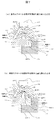
- the configuration of the back pressure control means 106 will be described with reference to FIGS.
- FIG. 2 shows the back pressure control means 106 shown in FIG. 1 in detail.
- the back pressure control means 106 includes a seal member 107, a spring 108, a valve body 109, and a seat portion 110, and is provided between the inlet communication passage 200 and the outlet communication passage 201.
- the inlet communication passage 200 opens on the sliding surface of the fixed scroll 20 with the base plate 100 of the orbiting scroll, and serves to communicate the back pressure chamber 102 and the back pressure control means 106.
- the inlet communication passage 200 includes an inlet communication passage 301 on the back pressure chamber 102 side and an inlet communication passage 302 on the back pressure control means 106 side, and the cross sectional area S 1 of the passage 301 is larger than the cross sectional area S 2 of the passage 302. It is configured.
- the outlet communication passage 201 opens on the suction groove 202 of the fixed scroll on the outlet side, and serves to communicate the back pressure control means 106 and the suction groove 202.
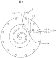
- FIG. 3 is a bottom view of the fixed scroll 20 shown in FIGS.
- the suction groove 202 communicates with the suction space 203.
- the outlet communication passage 201 may be configured to open to an intermediate pressure groove 204 communicating with the compression chamber 2 as shown in FIG.
- a configuration FIG. 3 that opens to the suction groove 202 will be described as an example.
- the valve body 109 is pressed against the seat portion 110 by the spring load of the spring 108 when the compressor is stopped.
- the pressure in the suction groove 202 communicating with the suction space 203 decreases, and the upper pressure P3 of the valve body 109 is lower than the pressure P2 in the passage 302, which is the lower part of the valve body 109, via the outlet communication passage 201. Lower.
- the valve body 109 is opened, so that gas and oil flow into the suction groove 202 from the back pressure chamber 102. Then, back pressure control is performed to keep the pressure Pb of the back pressure chamber 102 at a predetermined pressure.
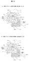
- FIG. 5 is a diagram illustrating a positional relationship between the base plate 100 of the orbiting scroll and the inlet communication passage 200 in the first embodiment. Since the orbiting scroll base plate 100 orbits, the outer peripheral end of the base plate moves under the entrance communication passage 200.
- the opening 300 is configured in a state where a part of the inlet of the inlet communication passage 301 on the back pressure chamber side is covered with the base plate 100 of the orbiting scroll.
- the area S0 of the opening 300 is always equal to or smaller than the sectional area S2 of the inlet communication passage 302 on the back pressure control means 106 side, and the passage 301 and the outer peripheral space 101 are always in communication.
- the outer peripheral space 101 of the orbiting scroll base plate is in communication with the back pressure chamber 102 of the orbiting scroll base plate 100 via the passage 303, but the outer peripheral pressure P0 is smaller than the back pressure Pb.
- a change in the pressure difference applied by the gas compression action accompanying the movement of 100 occurs.
- the pressure becomes highest at the position where the base plate 100 of the orbiting scroll is closest to the outer peripheral part, and as shown in (b), the position closer to the inner side (the furthest away from the outer peripheral part). Position) pressure is lowest.
- the valve body 109 causes abnormal vibration due to the pressure fluctuation, and the flow rate of gas and oil passing through the back pressure control means 106 increases. This causes a decrease in the back pressure Pb.
- the passage 301 becomes an enlarged space between the narrowed opening 300 and the narrowed passage 302 as described above, so that the fluctuation of the outer peripheral pressure P0 is propagated into the passage 302. The effect of suppressing and reducing the fluctuation
- the pressing force of the orbiting scroll 19 to the fixed scroll 20 can be properly maintained, and the oil supply to the compression chamber can be properly ensured, so that the refrigerant leakage loss during the compression operation is suppressed and the energy efficiency is improved. be able to.
- the reliability of the sliding of the orbiting scroll 19 can be ensured by optimizing the back pressure. Therefore, a scroll compressor capable of realizing high reliability and high energy efficiency can be obtained.
- FIG. 6 corresponds to FIG.
- the area S0 of the opening 300 is always equal to or smaller than the cross-sectional area S2 of the inlet communication passage 302 on the back pressure control means side.
- the base plate 100 of the orbiting scroll has time to temporarily close the inlet communication passage 301 on the back pressure chamber side, and the passage 301 and the outer peripheral space 101 are intermittent. It is the point which is comprised so that it may communicate with.
- the passage 301 and the outer peripheral space 101 are configured not to communicate with each other, whereby the pressure P2 in the passage 302 can be more stably maintained. The malfunction of the pressure Pb can be prevented.
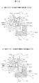
- FIG. 7 is a view corresponding to FIG. 5, and FIG. 8 is a bottom view of the fixed scroll in the third embodiment, and is a view for explaining the shape of the groove 104 provided in the fixed scroll.
- a groove 104 extending from the inlet communication passage 301 on the back pressure chamber side to the outer peripheral side is provided on the base plate surface of the fixed scroll, and the base plate 100 of the orbiting scroll is located under the groove 104.
- the outer peripheral end of the groove 104 is always located outside the outer peripheral end of the base plate 100 of the orbiting scroll.
- the sectional area S0 of the groove 104 is configured to be equal to or smaller than the sectional area S2 of the inlet communication passage 302 on the back pressure control means side.
- the passage 301 is an enlarged space between the narrowed groove 104 and the narrowed passage 302, the fluctuation of the outer peripheral pressure P0 is prevented from propagating into the passage 302, and the fluctuation of the pressure P2 is reduced. An effect is acquired and the malfunction of the fall of the back pressure Pb can be prevented.
- the intended configuration of the present invention may be difficult in dimension depending on the size of the turning radius.
- the configuration is not affected by the turning radius. It can be easily configured by adjusting the length of the groove 104.
- FIG. 9 corresponds to FIG.
- the fourth embodiment is different from the third embodiment in that the outer peripheral end of the groove 104 is temporarily located inside the outer peripheral end of the base plate 100 of the orbiting scroll.
- the inlet communication passage 301 on the back pressure chamber side and the outer peripheral space 101 can be configured to communicate intermittently.
- the passage 301 and the outer peripheral space 101 can be configured not to communicate with each other, whereby the pressure P2 in the inlet communication passage 302 on the back pressure control means side is more stable. Can be kept in.
- the intended configuration of the present invention may be dimensionally difficult depending on the size of the turning radius.
- this fourth embodiment as well, without being affected by the turning radius, It can be easily configured by adjusting the length of the groove 104.
- FIG. 10 is a diagram corresponding to FIG. 5, and FIG. 11 is a plan view of the orbiting scroll in the fifth embodiment, and is a diagram for explaining the shape of the groove 103 provided in the orbiting scroll.
- a groove 103 extending to the outer peripheral end is provided on the base plate surface of the orbiting scroll, and the inlet communication passage 301 on the back pressure chamber side of the fixed scroll is always positioned on the groove 103. It is comprised so that the said channel
- the cross-sectional area S0 of the groove 103 is configured to be equal to or smaller than the cross-sectional area S2 of the inlet communication passage 302 on the back pressure control means side. Since the passage 301 becomes an enlarged space between the narrowed groove 103 and the narrowed passage 302, the fluctuation of the outer peripheral pressure P0 is suppressed from being propagated into the passage 302, and the fluctuation of the pressure P2 is reduced. As a result, the problem of a decrease in the back pressure Pb can be prevented.
- the intended configuration of the present invention may be difficult in dimension depending on the size of the turning radius, but according to the fifth embodiment, without being affected by the turning radius, It can be easily configured by adjusting the length of the groove 103.
- FIG. 12 corresponds to FIG.
- the sixth embodiment is different from the fifth embodiment in that an inlet communication passage 301 on the back pressure chamber side of the fixed scroll is temporarily positioned on the groove 103, and the outer periphery of the passage 301 is It is the point which comprised so that the space 101 might communicate intermittently.
- the passage 301 and the outer peripheral space 101 not to communicate with each other when the outer peripheral pressure P0 is high, the pressure P2 in the inlet communication passage 302 on the back pressure control means side can be maintained more stably.
- the intended configuration of the present invention may be difficult in dimension depending on the size of the turning radius, but according to the sixth embodiment, without being affected by the turning radius, It can be easily configured by adjusting the length of the groove 103.
- FIG. 13 is a view corresponding to FIG. 5, and FIG. 14 is a plan view of the orbiting scroll in the seventh embodiment, and is a view for explaining the shape of the hole 105 provided in the orbiting scroll.
- a hole 105 is provided in the base plate surface of the orbiting scroll, and the inlet communication passage 301 on the back pressure chamber side of the fixed scroll is always positioned above the hole 105, and the passage 301 and the outer periphery space 101 are always connected.
- the cross-sectional area S0 of the hole 105 is configured to be equal to or smaller than the cross-sectional area S2 of the inlet communication passage 302 on the back pressure control means side. Since the passage 301 becomes an expanded space between the narrowed hole 105 and the narrowed passage 302, the fluctuation of the outer peripheral pressure P0 is suppressed from being propagated into the passage 302, and the fluctuation of the pressure P2 is suppressed. The effect of reducing the size can be obtained, and the problem of a decrease in the back pressure Pb can be prevented.
- FIG. 15 corresponds to FIG.
- This embodiment differs from the seventh embodiment in that an inlet communication passage 301 on the back pressure chamber side of the fixed scroll is temporarily positioned above the hole 105, and the passage 301 and the outer peripheral space are 101 is configured to communicate intermittently.
- the passage 301 and the outer peripheral space 101 not to communicate with each other when the outer peripheral pressure P0 is high, the pressure P2 in the inlet communication passage 302 on the back pressure control means side can be maintained more stably.
Landscapes
- Engineering & Computer Science (AREA)
- Mechanical Engineering (AREA)
- General Engineering & Computer Science (AREA)
- Rotary Pumps (AREA)
Abstract
スクロール圧縮機は、旋回スクロールと固定スクロールとの間に吸入室及び圧縮室を形成し、旋回スクロールの背面には吸入室より高い圧力により旋回スクロールに固定スクロールへの押付け力を与える背圧室を備える。固定スクロールには、吸込室または圧縮室と背圧室とを連通する連絡通路200,201と、該連絡通路の途中に差圧により該通路を開閉する背圧制御手段を備えている。前記背圧制御手段から背圧室までの入口連絡通路200は、少なくとも2つ以上の通路断面積で構成され、この入口連絡通路の背圧室側入口連絡通路301の断面積を、背圧制御手段側の入口連絡通路302の断面積より大きく構成している。また、前記通路301の背圧室側開口部300の一部が前記旋回スクロールの台板で常時塞がれるようにして、通路301の背圧室側開口面積が、常時通路302の断面積以下となるように構成し、高効率且つ高信頼性のスクロール圧縮機を実現する。
Description
本発明は冷凍、空調用の冷媒圧縮機や、空気などの気体を圧縮する圧縮機などに適用されるスクロール圧縮機に関する。
従来のスクリュー圧縮機としては、例えば特開2005-163655号公報(特許文献1)に記載のものがある。この従来技術のものでは、「非旋回スクロール部材と、この非旋回スクロール部材と噛み合って旋回運動をすることにより吸込室または圧縮室を形成する旋回スクロール部材と、スクロール部材に非旋回スクロール部材への押付け力を与える背圧室と、背圧室の圧力である背圧を維持するべく背圧室に流体を流入させる背圧室流体流入手段と、その流入した流体を吸込室または圧縮室に流出させる背圧室流体流出手段とを備える。背圧室流体流出手段は、背圧室と吸込室または圧縮室とを繋ぐ背圧室流体流出路に、前後の差圧を制御する背圧制御弁と絞り流路部と旋回スクロール部材の旋回運動により間欠的に連通する間欠流路部とを直列に配してなる。」と記載されている。
スクロール圧縮機では旋回スクロール部材の旋回運動に伴い、背圧室の旋回端板側面部でのガスおよび油圧縮作用が生じる。特許文献1では旋回外周溝を設けてガスおよび油圧縮の回避を実施しており、背圧室の旋回端板側面部の圧力変動を緩和しているが、圧力変動は皆無ではないので、背圧弁流入穴部の圧力が変動する。旋回端板側面部の圧力が最も高くなるのは旋回端板が最も外周側に寄った状態の時であり、圧力が最も低くなるのは旋回端板が最も外周側から離れた状態の時である。旋回端板側面部の圧力変動が背圧弁板に直接作用すると背圧弁の異常振動を促し、背圧弁に流入する流体量が増加し、背圧が所望の圧力より低くなり、適正な旋回スクロール押上げ力が確保できず、効率低下等の不具合が発生する。上記特許文献1のものでは、旋回端板側面部の圧力が最も高くなる時に背圧弁流入穴部を旋回端板で塞ぐ間欠構造となっているので、背圧弁流入穴部の圧力変動幅は旋回端板側面部の圧力変動幅に対しては小さくなっているが、旋回端板側面部の圧力が最も低くなる時は背圧弁流入穴部が全開となり、旋回端板側面部の圧力が背圧弁板に直接作用する状態になるため、高速回転で圧力変動が大きくなる条件では上記の背圧低下の不具合が発生する恐れがあった。
本発明の目的は、差圧で開閉する背圧制御手段を有するスクロール圧縮機において、旋回端板側面部の圧力変動が大きくなる運転条件下でも背圧を適正安定に保ち、高効率で信頼性の高い圧縮機を得ることにある。
上記目的を達成するため、本発明は、台板に渦巻き形状を有する固定スクロール及び旋回スクロールを互いに噛み合わせ、該旋回スクロールを駆動させるクランク軸を備え、該クランク軸の回転に伴って前記旋回スクロールが旋回運動することにより前記旋回スクロールと前記固定スクロールとの間に吸入室及び圧縮室を形成し、前記旋回スクロールの背面には前記吸入室より高い圧力により前記旋回スクロールに前記固定スクロールへの押し付け力を与える背圧室を有し、前記固定スクロールに、前記吸込室または前記圧縮室と前記背圧室とを連通する連絡通路と、該連絡通路の途中に差圧により該連絡通路を開閉する背圧制御手段を備えたスクロール圧縮機において、前記連絡通路の背圧制御手段から前記背圧室までの入口連絡通路を少なくとも2つ以上の通路断面積で構成し、この入口連絡通路の背圧室側の入口連絡通路断面積を、背圧制御手段側の入口連絡通路断面積より大きく構成し、前記背圧室側の入口連絡通路の背圧室側開口部の一部が前記旋回スクロールの台板で常時塞がれるようにして、この背圧室側入口連絡通路の背圧室側開口面積が、常時前記背圧制御手段側の入口連絡通路断面積以下となるように構成したことを特徴とする。
前記連絡通路の背圧室側開口部を前記旋回スクロールの台板で開閉することで前記連絡通路を間欠的に連通させるように構成した場合においても、前記連絡通路の背圧室側の開口面積が最大開口時でも前記背圧制御手段側の連絡通路断面積以下となるように構成しても良い。
また、前記背圧室側入口連絡通路の背圧室側開口部は、その一部に外周側に延びる溝が設けられ、該溝の端部が背圧室側に開口するように当該溝を旋回スクロールの台板で塞ぎ、前記溝の開口面積が常時前記背圧制御手段側の入口連絡通路断面積以下となるように構成しても良い。
或いは、前記旋回スクロールの台板に、前記背圧室側入口連絡通路の背圧室側開口部と背圧室を連通する溝または穴を設け、該溝または穴の開口面積が前記背圧制御手段側の入口連絡通路の断面積以下となるように構成しても良い。
本発明によれば、差圧で開閉する背圧制御手段を有するスクロール圧縮機において、吸込室または圧縮室と背圧室をつなぐ連絡通路の背圧室側の連絡通路断面積を背圧制御手段の連絡通路断面積より大きく構成し、且つ背圧室側の開口面積を常時背圧制御手段側の連絡通路断面積以下となるように構成しているので、通路の拡大縮小による圧力変動伝播抑制効果が得られる。このため、旋回端板側面部の圧力変動が大きくなる運転条件下でも背圧制御手段に作用する圧力変動が抑えられ、背圧制御手段の異常振動を防止できるので、背圧をより適正安定に保ち、高効率で信頼性の高いスクロール圧縮機を得ることができる。
以下、本発明の具体的実施例を図面に基づいて説明する。各図において、同一符号を付した部分は同一または相当する部分を示している。
図1に本発明のスクロール圧縮機の実施例1を示す。まず、スクロール圧縮機の全体構造に関して説明する。スクロール圧縮機1は、密閉容器21に固定スクロール20旋回スクロール19から成る圧縮部と駆動部3が収められている。駆動部3は、固定子8と回転子9からなる電動機10と、クランク軸11と、フレーム12と、副フレーム13と、副軸受ハウジング16を基本要素として構成する。ここで、電動機10は、電気端子17を経由したインバータ(図示せず)からの電気入力により駆動され、回転作用をクランク軸11へ付与する。クランク軸11は、主軸部11aと副軸部11bと偏心ピン部11cとを備えて構成する。フレーム12に配設した軸支持部14、副軸受ハウジング16に配設した軸支持部15は、クランク軸11の主軸部11aと副軸部11bを回転自在に支持する軸支持部を構成する。また、前記軸支持部14、15の潤滑のための油18が密閉容器21内に蓄えられている。フレーム12と、副軸受ハウジング16と結合されている副フレーム13は、密閉容器21に固定される。クランク軸11の回転作用により、固定スクロール20と旋回スクロール19を噛み合わせることにより機械的に構成した圧縮室2の容積を減少させて圧縮動作を行う。作動流体は吸込管6から圧縮室2へ吸込まれ、圧縮行程を経て吐出ポート4から密閉容器21内の吐出空間5に吐出され、更に吐出管7から密閉容器21外へ吐出される。
圧縮室2の密閉性を保つため、吐出圧と吸込圧の間の中間的な圧力(以下、背圧と呼称)を旋回スクロール19の背面空間(以下、背圧室102と呼称)に作用させ、旋回スクロール19を固定スクロール20へ押付ける。固定スクロール20に設けた背圧制御手段106により背圧を生成し適正に保つことで、圧縮動作時における冷媒漏れによるエネルギー損失を低減し、且つ旋回スクロール19の押付け摺動に関して良好な信頼性を確保することができる。
図2~図4を用いて背圧制御手段106の構成について説明する。図2は、図1に示した背圧制御手段106を詳細に示したものである。背圧制御手段106は、シール部材107、バネ108、弁体109、シート部110で構成され、入口連絡通路200と出口連絡通路201との間に設けられている。入口連絡通路200は、入口側が固定スクロール20の旋回スクロールの台板100との摺動面に開口し、背圧室102と背圧制御手段106とを連通する役目をする。入口連絡通路200は、背圧室102側の入口連絡通路301と、背圧制御手段106側の入口連絡通路302で構成し、前記通路301の断面積S1は前記通路302の断面積S2より大きく構成されている。
前記出口連絡通路201は、出口側が固定スクロールの吸入溝202に開口し、背圧制御手段106と吸入溝202を連通する役目をする。
前記出口連絡通路201は、出口側が固定スクロールの吸入溝202に開口し、背圧制御手段106と吸入溝202を連通する役目をする。
図3は図1、図2に示す固定スクロール20の底面図である。図3のように、吸入溝202は吸込空間203に連通している。なお、前記出口連絡通路201は図4のように圧縮室2に連通する中間圧力溝204に開口する構成としても良い。以下の説明では、吸入溝202に開口する構成(図3)を例として説明する。
図2に示すように、圧縮機停止状態においては、弁体109はバネ108のバネ荷重によりシート部110に押し付けられている。圧縮機運転状態においては、吸入空間203に連通する吸入溝202の圧力が下がり、出口連絡通路201を介して弁体109の上部圧力P3が弁体109の下部である通路302内の圧力P2より低くなる。圧力P2と圧力P3の圧力差で弁体109に作用する荷重がバネ108のバネ荷重より大きくなると弁体109が開弁することで、背圧室102からガスおよび油が吸入溝202に流入し、背圧室102の圧力Pbを所定の圧力に保つ背圧制御を行う。
図5は、実施例1における旋回スクロールの台板100と入口連絡通路200との位置関係を示す図である。旋回スクロールの台板100は旋回運動するため、台板外周端が入口連絡通路200の下で移動する。背圧室側の入口連絡通路301の入口の一部を旋回スクロールの台板100で塞いだ状態で開口部300が構成される。開口部300の面積S0は常に背圧制御手段106側の入口連絡通路302の断面積S2と同等以下になるように構成されており、前記通路301と外周空間101とが常時連通している。
旋回スクロールの台板の外周空間101は、旋回スクロールの台板100の背圧室102と通路303を介して連通しているが、外周部圧力P0は背圧Pbに対して旋回スクロールの台板100の移動に伴うガス圧縮作用で加わる圧力差分の変動が生じる。(a)図に示すように、旋回スクロールの台板100が外周部に最も寄った位置で圧力は最も高くなり、(b)図に示すように、内側寄りの位置(外周部から最も離れた位置)で圧力は最も低くなる。外周部圧力P0の変動が直接弁体109の下部である通路302に伝播すると弁体109が圧力変動の影響で異常振動を起こし、背圧制御手段106を通過するガス及び油の流量が増加し、背圧Pbの低下を招く。本実施例では、前記通路301は前述の通り、絞られた開口部300と絞られた通路302との間の拡大空間となるため、外周部圧力P0の変動を通路302内に伝播するのを抑え、圧力P2の変動を小さくする効果が得られ、背圧Pbの低下の不具合を防止できる。
これにより旋回スクロール19の固定スクロール20への押付け力を適正に保つことができ、且つ圧縮室への給油も適正に確保できるから、圧縮動作時における冷媒漏れ損失を抑制し、エネルギー効率向上をすることができる。併せて、背圧の適正化により、旋回スクロール19の摺動に関する信頼性を確保することもできる。従って、高い信頼性と高いエネルギー効率を実現できるスクロール圧縮機が得られる。
図6により本発明のスクロール圧縮機の実施例2を説明する。図6は図5に相当する図である。
本実施例においても上記実施例1と同様に、開口部300の面積S0は常に背圧制御手段側の入口連絡通路302の断面積S2と同等以下になるように構成されている。実施例1との相違点は、旋回スクロールの台板100が、背圧室側の入口連絡通路301を、一時的に全閉にする時間があり、前記通路301と外周空間101とが間欠的に連通するように構成している点である。本実施例のように、外周部圧力P0が高い時には、前記通路301と外周空間101とが連通されないように構成することにより、通路302内の圧力P2をより安定して保つことができ、背圧Pbの低下の不具合を防止できる。
本実施例においても上記実施例1と同様に、開口部300の面積S0は常に背圧制御手段側の入口連絡通路302の断面積S2と同等以下になるように構成されている。実施例1との相違点は、旋回スクロールの台板100が、背圧室側の入口連絡通路301を、一時的に全閉にする時間があり、前記通路301と外周空間101とが間欠的に連通するように構成している点である。本実施例のように、外周部圧力P0が高い時には、前記通路301と外周空間101とが連通されないように構成することにより、通路302内の圧力P2をより安定して保つことができ、背圧Pbの低下の不具合を防止できる。
図7、図8により本発明のスクロール圧縮機の実施例3を説明する。図7は図5に相当する図、図8は実施例3における固定スクロールの底面図で、固定スクロールに設けられた溝104の形状を説明する図である。
本実施例では、固定スクロールの台板面に、背圧室側の入口連絡通路301から外周側に延びる溝104が設けられており、その溝104の下に旋回スクロールの台板100が位置し、溝104の外周端は常に旋回スクロールの台板100の外周端より外側にあるように構成されている。これにより、前記背圧室側の入口連絡通路301と外周空間101とが常時連通する構成としている。前記溝104の断面積S0は背圧制御手段側の入口連絡通路302の断面積S2と同等以下になるように構成されている。前記通路301は絞られた溝104と絞られた前記通路302との間の拡大空間となるため、外周部圧力P0の変動を通路302内に伝播するのを抑え、圧力P2の変動を小さくする効果が得られ、背圧Pbの低下の不具合を防止できる。
上記実施例1または実施例2の場合、旋回半径の大きさによって、本発明の意図する構成が寸法的に難しい場合があるが、この実施例3によれば旋回半径の影響を受けず、前記溝104の長さを調整することで容易に構成できる。
図9により本発明のスクロール圧縮機の実施例4を説明する。図9は図5に相当する図である。
本実施例4が前記実施例3と相違する点は、溝104の外周端は一時的に旋回スクロールの台板100の外周端より内側となるように構成している点である。このように構成することにより、背圧室側の入口連絡通路301と外周空間101とが間欠的に連通するように構成することができる。本実施例では、外周部圧力P0が高い時には前記通路301と外周空間101とが連通しないように構成することができ、これにより背圧制御手段側の入口連絡通路302内の圧力P2をより安定に保つことができる。
本実施例4が前記実施例3と相違する点は、溝104の外周端は一時的に旋回スクロールの台板100の外周端より内側となるように構成している点である。このように構成することにより、背圧室側の入口連絡通路301と外周空間101とが間欠的に連通するように構成することができる。本実施例では、外周部圧力P0が高い時には前記通路301と外周空間101とが連通しないように構成することができ、これにより背圧制御手段側の入口連絡通路302内の圧力P2をより安定に保つことができる。
上記実施例1または実施例2の場合、旋回半径の大きさによって、本発明の意図する構成が寸法的に難しい場合があるが、この実施例4においても、旋回半径の影響を受けずに、溝104の長さを調整することで容易に構成できる。
図10、図11により本発明のスクロール圧縮機の実施例5を説明する。図10は図5に相当する図、図11は実施例5における旋回スクロールの平面図で、旋回スクロールに設けられた溝103の形状を説明する図である。
本実施例では、旋回スクロールの台板面に、その外周端に延びる溝103が設けられており、該溝103の上に、常時固定スクロールの背圧室側の入口連絡通路301が位置するように構成されており、前記通路301と外周空間101とが常時連通するように構成されている。前記溝103の断面積S0は背圧制御手段側の入口連絡通路302の断面積S2と同等以下になるように構成されている。前記通路301は絞られた溝103と絞られた前記通路302との間の拡大空間となるため、外周部圧力P0の変動を前記通路302内に伝播するのを抑え、圧力P2の変動を小さくする効果が得られるので、背圧Pbの低下の不具合を防止できる。
上記実施例1または実施例2の場合、旋回半径の大きさによって、本発明の意図する構成が寸法的に難しい場合があるが、本実施例5によれば旋回半径の影響を受けずに、溝103の長さを調整することで容易に構成できる。
図12により本発明のスクロール圧縮機の実施例6を説明する。図12は図5に相当する図である。
本実施例6が上記実施例5と相違する点は、前記溝103の上に、一時的に固定スクロールの背圧室側の入口連絡通路301が位置するように構成され、前記通路301と外周空間101とが間欠的に連通するように構成した点である。外周部圧力P0が高い時には前記通路301と外周空間101とが連通しないように構成することにより、背圧制御手段側の入口連絡通路302内の圧力P2をより安定して保つことができる。
本実施例6が上記実施例5と相違する点は、前記溝103の上に、一時的に固定スクロールの背圧室側の入口連絡通路301が位置するように構成され、前記通路301と外周空間101とが間欠的に連通するように構成した点である。外周部圧力P0が高い時には前記通路301と外周空間101とが連通しないように構成することにより、背圧制御手段側の入口連絡通路302内の圧力P2をより安定して保つことができる。
上記実施例1または実施例2の場合、旋回半径の大きさによって、本発明の意図する構成が寸法的に難しい場合があるが、本実施例6によれば旋回半径の影響を受けずに、溝103の長さを調整することで容易に構成できる。
図13、図14により本発明のスクロール圧縮機の実施例7を説明する。図13は図5に相当する図、図14は実施例7における旋回スクロールの平面図で、旋回スクロールに設けられた穴105の形状を説明する図である。
本実施例では、旋回スクロールの台板面に穴105が設けられており、その穴105の上に、常時固定スクロールの背圧室側の入口連絡通路301が位置するように構成され、前記通路301と外周空間101とが常時連通する構成としている。前記穴105の断面積S0は、背圧制御手段側の入口連絡通路302の断面積S2と同等以下になるように構成されている。前記通路301は絞られた前記穴105と絞られた前記通路302との間の拡大空間となるため、外周部圧力P0の変動を前記通路302内に伝播するのを抑え、圧力P2の変動を小さくする効果が得られ、背圧Pbの低下の不具合を防止できる。
図15により本発明のスクロール圧縮機の実施例8を説明する。図15は図5に相当する図である。
本実施例が上記実施例7と相違する点は、前記穴105の上に、一時的に固定スクロールの背圧室側の入口連絡通路301が位置するように構成され、前記通路301と外周空間101とが間欠的に連通するように構成している点である。外周部圧力P0が高い時には前記通路301と外周空間101とが連通しないように構成することにより、背圧制御手段側の入口連絡通路302内の圧力P2をより安定して保つことができる。
本実施例が上記実施例7と相違する点は、前記穴105の上に、一時的に固定スクロールの背圧室側の入口連絡通路301が位置するように構成され、前記通路301と外周空間101とが間欠的に連通するように構成している点である。外周部圧力P0が高い時には前記通路301と外周空間101とが連通しないように構成することにより、背圧制御手段側の入口連絡通路302内の圧力P2をより安定して保つことができる。
1:スクロール圧縮機、2:圧縮室、3:駆動部、4:吐出ポート、5:吐出空間、
6:吸込管、7:吐出管、8:固定子、9:回転子、10:電動機、
11:クランク軸、12:フレーム、13:副フレーム、
14,15:軸支持部、16:副軸受ハウジング、
17:電気端子、18:油、19:旋回スクロール、20:固定スクロール、
21:密閉容器、
100:旋回スクロール台板、101:旋回スクロール台板の外周空間、
102:背圧室、
103,104:溝、105:穴、106:背圧制御手段、
107:シール部材、108:バネ、109:弁体、110:シート部、
200:入口連絡通路、201:出口連絡通路、
202:吸入溝、203:吸入空間、204:中間圧力溝、
300:開口部、
301:背圧室側の入口連絡通路、302:背圧制御手段側の入口連絡通路、
303:背圧室と旋回スクロール台板外周空間との連絡通路、
S0:開口部断面積、S1:背圧室側入口連絡通路の断面積、
S2:背圧制御手段側入口連絡通路の断面積、
P0:開口部断面積圧力、P1:背圧室側入口連絡通路の圧力、
P2:背圧制御手段側入口連絡通路の圧力、
P3:出口連絡通路の圧力、Pb:背圧室の圧力。
Claims (5)
- 台板に渦巻き形状を有する固定スクロール及び旋回スクロールを互いに噛み合わせ、該旋回スクロールを駆動させるクランク軸を備え、該クランク軸の回転に伴って前記旋回スクロールが旋回運動することにより前記旋回スクロールと前記固定スクロールとの間に吸入室及び圧縮室を形成し、前記旋回スクロールの背面には前記吸入室より高い圧力により前記旋回スクロールに前記固定スクロールへの押し付け力を与える背圧室を有し、
前記固定スクロールに、前記吸込室または前記圧縮室と前記背圧室とを連通する連絡通路と、該連絡通路の途中に差圧により該連絡通路を開閉する背圧制御手段を備えたスクロール圧縮機において、
前記連絡通路の背圧制御手段から前記背圧室までの入口連絡通路を少なくとも2つ以上の通路断面積で構成し、この入口連絡通路の背圧室側の入口連絡通路断面積を、背圧制御手段側の入口連絡通路断面積より大きく構成し、
前記背圧室側の入口連絡通路の背圧室側開口部の一部が前記旋回スクロールの台板で常時塞がれるようにして、この背圧室側入口連絡通路の背圧室側開口面積が、常時前記背圧制御手段側の入口連絡通路断面積以下となるように構成したことを特徴とするスクロール圧縮機。 - 請求項1に記載のスクロール圧縮機において、前記背圧室側入口連絡通路の背圧室側開口部は、その一部に外周側に延びる溝が設けられ、該溝の端部が背圧室側に開口するように当該溝を旋回スクロールの台板で塞ぎ、前記溝の開口面積が常時前記背圧制御手段側の入口連絡通路断面積以下となるように構成したことを特徴とするスクロール圧縮機。
- 請求項1に記載のスクロール圧縮機において、前記旋回スクロールの台板に、前記背圧室側入口連絡通路の背圧室側開口部と背圧室を連通する溝を設け、該溝の開口面積が前記背圧制御手段側の入口連絡通路の断面積以下となるように構成したことを特徴とするスクロール圧縮機。
- 請求項1に記載のスクロール圧縮機において、前記旋回スクロールの台板に、前記背圧室側入口連絡通路の背圧室側開口部と背圧室を連通する穴を設け、該穴の面積が前記背圧制御手段側の入口連絡通路の断面積以下となるように構成したことを特徴とするスクロール圧縮機。
- 台板に渦巻き形状を有する固定スクロール及び旋回スクロールを互いに噛み合わせ、該旋回スクロールを駆動させるクランク軸を備え、該クランク軸の回転に伴って前記旋回スクロールが旋回運動することにより前記旋回スクロールと前記固定スクロールとの間に吸入室及び圧縮室を形成し、前記旋回スクロールの背面には前記吸入室より高い圧力により前記旋回スクロールに前記固定スクロールへの押し付け力を与える背圧室を有し、
前記固定スクロールに、前記吸込室または前記圧縮室と前記背圧室とを連通する連絡通路と、該連絡通路の途中に差圧により該連絡通路を開閉する背圧制御手段を備え、
且つ前記連絡通路の背圧室側の開口部を前記旋回スクロールの台板で開閉することで前記連絡通路を間欠的に連通させるようにしたスクロール圧縮機において、
前記連絡通路の背圧制御手段から前記背圧室までの入口連絡通路を少なくとも2つ以上の通路断面積で構成し、この入口連絡通路の背圧室側の入口連絡通路断面積を、背圧制御手段側の入口連絡通路断面積より大きく構成し、
前記背圧室側入口連絡通路の背圧室側開口部が最大に開口した状態においても、該開口部の一部分が前記旋回スクロールの台板で塞がれるようにすると共に、前記背圧室側連絡通路の背圧室側開口面積が前記背圧制御手段側の入口連絡通路の断面積以下となるように構成したことを特徴とするスクロール圧縮機。
Priority Applications (5)
| Application Number | Priority Date | Filing Date | Title |
|---|---|---|---|
| EP11862770.2A EP2693056B1 (en) | 2011-03-29 | 2011-03-29 | Scroll compressor |
| JP2013506920A JP5507756B2 (ja) | 2011-03-29 | 2011-03-29 | スクロール圧縮機 |
| PCT/JP2011/057824 WO2012131904A1 (ja) | 2011-03-29 | 2011-03-29 | スクロール圧縮機 |
| CN201180068400.0A CN103384769B (zh) | 2011-03-29 | 2011-03-29 | 涡旋压缩机 |
| US14/000,941 US9091266B2 (en) | 2011-03-29 | 2011-03-29 | Scroll compressor having a back pressure control valve for opening and closing a communication path in a stationary scroll |
Applications Claiming Priority (1)
| Application Number | Priority Date | Filing Date | Title |
|---|---|---|---|
| PCT/JP2011/057824 WO2012131904A1 (ja) | 2011-03-29 | 2011-03-29 | スクロール圧縮機 |
Publications (1)
| Publication Number | Publication Date |
|---|---|
| WO2012131904A1 true WO2012131904A1 (ja) | 2012-10-04 |
Family
ID=46929737
Family Applications (1)
| Application Number | Title | Priority Date | Filing Date |
|---|---|---|---|
| PCT/JP2011/057824 WO2012131904A1 (ja) | 2011-03-29 | 2011-03-29 | スクロール圧縮機 |
Country Status (5)
| Country | Link |
|---|---|
| US (1) | US9091266B2 (ja) |
| EP (1) | EP2693056B1 (ja) |
| JP (1) | JP5507756B2 (ja) |
| CN (1) | CN103384769B (ja) |
| WO (1) | WO2012131904A1 (ja) |
Cited By (2)
| Publication number | Priority date | Publication date | Assignee | Title |
|---|---|---|---|---|
| JP2015206329A (ja) * | 2014-04-23 | 2015-11-19 | 日立アプライアンス株式会社 | スクロール圧縮機 |
| CN106015010A (zh) * | 2016-07-04 | 2016-10-12 | 珠海凌达压缩机有限公司 | 压缩机定子及压缩机 |
Families Citing this family (6)
| Publication number | Priority date | Publication date | Assignee | Title |
|---|---|---|---|---|
| KR101731449B1 (ko) * | 2015-12-09 | 2017-04-28 | 엘지전자 주식회사 | 스크롤 압축기 |
| CN105604935B (zh) * | 2016-02-01 | 2018-10-26 | 珠海格力节能环保制冷技术研究中心有限公司 | 压缩机及具有其的空调器 |
| KR101892803B1 (ko) * | 2016-04-26 | 2018-08-29 | 학교법인 두원학원 | 스크롤 압축기의 배압제어 수단 |
| JP6343328B2 (ja) * | 2016-11-21 | 2018-06-13 | 日立ジョンソンコントロールズ空調株式会社 | スクロール圧縮機 |
| WO2019216834A1 (en) | 2018-05-07 | 2019-11-14 | Siam Compressor Industry Co., Ltd. | Power supply wire connecting structure for hermetic compressor |
| JP6737308B2 (ja) * | 2018-07-05 | 2020-08-05 | ダイキン工業株式会社 | スクロール圧縮機 |
Citations (4)
| Publication number | Priority date | Publication date | Assignee | Title |
|---|---|---|---|---|
| JPH11132164A (ja) * | 1997-10-29 | 1999-05-18 | Hitachi Ltd | スクロール圧縮機 |
| JP2005163655A (ja) * | 2003-12-03 | 2005-06-23 | Hitachi Ltd | スクロール圧縮機 |
| JP2008002311A (ja) * | 2006-06-21 | 2008-01-10 | Matsushita Electric Ind Co Ltd | スクロール圧縮機 |
| JP2010053798A (ja) * | 2008-08-29 | 2010-03-11 | Hitachi Appliances Inc | スクロール圧縮機 |
Family Cites Families (12)
| Publication number | Priority date | Publication date | Assignee | Title |
|---|---|---|---|---|
| JPH05288166A (ja) * | 1992-04-10 | 1993-11-02 | Hitachi Ltd | スクロール圧縮機 |
| JP3806265B2 (ja) * | 1999-04-05 | 2006-08-09 | 松下電器産業株式会社 | スクロール圧縮機 |
| JP4376554B2 (ja) * | 2003-06-12 | 2009-12-02 | パナソニック株式会社 | スクロール圧縮機 |
| JP2005120939A (ja) * | 2003-10-17 | 2005-05-12 | Matsushita Electric Ind Co Ltd | スクロール圧縮機 |
| JP2006037896A (ja) * | 2004-07-29 | 2006-02-09 | Matsushita Electric Ind Co Ltd | スクロール圧縮機 |
| JP4488222B2 (ja) * | 2005-05-20 | 2010-06-23 | 株式会社富士通ゼネラル | スクロール圧縮機 |
| JP2007321685A (ja) * | 2006-06-02 | 2007-12-13 | Hitachi Appliances Inc | スクロール圧縮機及びそれを用いた冷凍サイクル装置 |
| JP2008002419A (ja) * | 2006-06-26 | 2008-01-10 | Matsushita Electric Ind Co Ltd | スクロール圧縮機 |
| JP4922988B2 (ja) * | 2008-04-30 | 2012-04-25 | 日立アプライアンス株式会社 | スクロール圧縮機 |
| JP4951586B2 (ja) * | 2008-05-30 | 2012-06-13 | 日立アプライアンス株式会社 | スクロール流体機械 |
| KR101576459B1 (ko) * | 2009-02-25 | 2015-12-10 | 엘지전자 주식회사 | 스크롤 압축기 및 이를 적용한 냉동기기 |
| JP5551644B2 (ja) | 2011-03-30 | 2014-07-16 | 日立アプライアンス株式会社 | スクロール圧縮機 |
-
2011
- 2011-03-29 EP EP11862770.2A patent/EP2693056B1/en not_active Not-in-force
- 2011-03-29 JP JP2013506920A patent/JP5507756B2/ja active Active
- 2011-03-29 US US14/000,941 patent/US9091266B2/en active Active
- 2011-03-29 WO PCT/JP2011/057824 patent/WO2012131904A1/ja active Application Filing
- 2011-03-29 CN CN201180068400.0A patent/CN103384769B/zh active Active
Patent Citations (4)
| Publication number | Priority date | Publication date | Assignee | Title |
|---|---|---|---|---|
| JPH11132164A (ja) * | 1997-10-29 | 1999-05-18 | Hitachi Ltd | スクロール圧縮機 |
| JP2005163655A (ja) * | 2003-12-03 | 2005-06-23 | Hitachi Ltd | スクロール圧縮機 |
| JP2008002311A (ja) * | 2006-06-21 | 2008-01-10 | Matsushita Electric Ind Co Ltd | スクロール圧縮機 |
| JP2010053798A (ja) * | 2008-08-29 | 2010-03-11 | Hitachi Appliances Inc | スクロール圧縮機 |
Non-Patent Citations (1)
| Title |
|---|
| See also references of EP2693056A4 * |
Cited By (3)
| Publication number | Priority date | Publication date | Assignee | Title |
|---|---|---|---|---|
| JP2015206329A (ja) * | 2014-04-23 | 2015-11-19 | 日立アプライアンス株式会社 | スクロール圧縮機 |
| CN106015010A (zh) * | 2016-07-04 | 2016-10-12 | 珠海凌达压缩机有限公司 | 压缩机定子及压缩机 |
| CN106015010B (zh) * | 2016-07-04 | 2019-02-26 | 珠海凌达压缩机有限公司 | 压缩机定子及压缩机 |
Also Published As
| Publication number | Publication date |
|---|---|
| JP5507756B2 (ja) | 2014-05-28 |
| EP2693056B1 (en) | 2019-01-23 |
| US9091266B2 (en) | 2015-07-28 |
| EP2693056A1 (en) | 2014-02-05 |
| US20140010693A1 (en) | 2014-01-09 |
| EP2693056A4 (en) | 2015-01-14 |
| CN103384769B (zh) | 2015-10-07 |
| JPWO2012131904A1 (ja) | 2014-07-24 |
| CN103384769A (zh) | 2013-11-06 |
Similar Documents
| Publication | Publication Date | Title |
|---|---|---|
| JP5507756B2 (ja) | スクロール圧縮機 | |
| JP5701230B2 (ja) | スクロール圧縮機 | |
| JP5489142B2 (ja) | スクロール圧縮機 | |
| JP4680616B2 (ja) | スクロール圧縮機の容量可変装置 | |
| JP2010106780A (ja) | スクロール圧縮機 | |
| JP2007154761A (ja) | スクロール圧縮機 | |
| KR100608664B1 (ko) | 스크롤 압축기의 용량 가변 장치 | |
| JPWO2005038254A1 (ja) | スクロール圧縮機 | |
| JP2007170253A (ja) | スクロール圧縮機 | |
| JP4697734B2 (ja) | 冷凍サイクル | |
| JP2006299806A (ja) | スクロール圧縮機 | |
| JP5551644B2 (ja) | スクロール圧縮機 | |
| CN113994098B (zh) | 涡旋式压缩机 | |
| JP4922988B2 (ja) | スクロール圧縮機 | |
| EP2541066B1 (en) | Scroll compressor | |
| JP4604968B2 (ja) | スクロール圧縮機 | |
| JP5690674B2 (ja) | スクロール圧縮機 | |
| JP4355308B2 (ja) | スクロール流体機械 | |
| JP6343328B2 (ja) | スクロール圧縮機 | |
| JP2008115767A (ja) | スクロール圧縮機 | |
| WO2014196314A1 (ja) | スクロール圧縮機及びこれを用いた空気調和機 | |
| JP2002364564A (ja) | スクロール流体機械 | |
| JP2006336543A (ja) | スクロール圧縮機 | |
| JP6416559B2 (ja) | スクロール圧縮機および空気調和機 | |
| JP2005163745A (ja) | スクロール圧縮機 |
Legal Events
| Date | Code | Title | Description |
|---|---|---|---|
| ENP | Entry into the national phase |
Ref document number: 2013506920 Country of ref document: JP Kind code of ref document: A |
|
| 121 | Ep: the epo has been informed by wipo that ep was designated in this application |
Ref document number: 11862770 Country of ref document: EP Kind code of ref document: A1 |
|
| WWE | Wipo information: entry into national phase |
Ref document number: 14000941 Country of ref document: US |
|
| NENP | Non-entry into the national phase |
Ref country code: DE |