WO2012128253A1 - 緩衝機能を有する包装用箱 - Google Patents
緩衝機能を有する包装用箱 Download PDFInfo
- Publication number
- WO2012128253A1 WO2012128253A1 PCT/JP2012/057022 JP2012057022W WO2012128253A1 WO 2012128253 A1 WO2012128253 A1 WO 2012128253A1 JP 2012057022 W JP2012057022 W JP 2012057022W WO 2012128253 A1 WO2012128253 A1 WO 2012128253A1
- Authority
- WO
- WIPO (PCT)
- Prior art keywords
- buffer
- plate
- packaging box
- support plate
- packaging
- Prior art date
- Legal status (The legal status is an assumption and is not a legal conclusion. Google has not performed a legal analysis and makes no representation as to the accuracy of the status listed.)
- Ceased
Links
Images





Classifications
-
- B—PERFORMING OPERATIONS; TRANSPORTING
- B65—CONVEYING; PACKING; STORING; HANDLING THIN OR FILAMENTARY MATERIAL
- B65D—CONTAINERS FOR STORAGE OR TRANSPORT OF ARTICLES OR MATERIALS, e.g. BAGS, BARRELS, BOTTLES, BOXES, CANS, CARTONS, CRATES, DRUMS, JARS, TANKS, HOPPERS, FORWARDING CONTAINERS; ACCESSORIES, CLOSURES, OR FITTINGS THEREFOR; PACKAGING ELEMENTS; PACKAGES
- B65D5/00—Rigid or semi-rigid containers of polygonal cross-section, e.g. boxes, cartons or trays, formed by folding or erecting one or more blanks made of paper
- B65D5/02—Rigid or semi-rigid containers of polygonal cross-section, e.g. boxes, cartons or trays, formed by folding or erecting one or more blanks made of paper by folding or erecting a single blank to form a tubular body with or without subsequent folding operations, or the addition of separate elements, to close the ends of the body
- B65D5/0254—Rigid or semi-rigid containers of polygonal cross-section, e.g. boxes, cartons or trays, formed by folding or erecting one or more blanks made of paper by folding or erecting a single blank to form a tubular body with or without subsequent folding operations, or the addition of separate elements, to close the ends of the body with end closures formed by inward folding of flaps and securing them by means of a tongue integral with one of the flaps
-
- B—PERFORMING OPERATIONS; TRANSPORTING
- B65—CONVEYING; PACKING; STORING; HANDLING THIN OR FILAMENTARY MATERIAL
- B65D—CONTAINERS FOR STORAGE OR TRANSPORT OF ARTICLES OR MATERIALS, e.g. BAGS, BARRELS, BOTTLES, BOXES, CANS, CARTONS, CRATES, DRUMS, JARS, TANKS, HOPPERS, FORWARDING CONTAINERS; ACCESSORIES, CLOSURES, OR FITTINGS THEREFOR; PACKAGING ELEMENTS; PACKAGES
- B65D5/00—Rigid or semi-rigid containers of polygonal cross-section, e.g. boxes, cartons or trays, formed by folding or erecting one or more blanks made of paper
- B65D5/02—Rigid or semi-rigid containers of polygonal cross-section, e.g. boxes, cartons or trays, formed by folding or erecting one or more blanks made of paper by folding or erecting a single blank to form a tubular body with or without subsequent folding operations, or the addition of separate elements, to close the ends of the body
- B65D5/10—Rigid or semi-rigid containers of polygonal cross-section, e.g. boxes, cartons or trays, formed by folding or erecting one or more blanks made of paper by folding or erecting a single blank to form a tubular body with or without subsequent folding operations, or the addition of separate elements, to close the ends of the body with end closures formed by inward-folding of self-locking flaps hinged to tubular body
-
- B—PERFORMING OPERATIONS; TRANSPORTING
- B65—CONVEYING; PACKING; STORING; HANDLING THIN OR FILAMENTARY MATERIAL
- B65D—CONTAINERS FOR STORAGE OR TRANSPORT OF ARTICLES OR MATERIALS, e.g. BAGS, BARRELS, BOTTLES, BOXES, CANS, CARTONS, CRATES, DRUMS, JARS, TANKS, HOPPERS, FORWARDING CONTAINERS; ACCESSORIES, CLOSURES, OR FITTINGS THEREFOR; PACKAGING ELEMENTS; PACKAGES
- B65D5/00—Rigid or semi-rigid containers of polygonal cross-section, e.g. boxes, cartons or trays, formed by folding or erecting one or more blanks made of paper
- B65D5/42—Details of containers or of foldable or erectable container blanks
- B65D5/44—Integral, inserted or attached portions forming internal or external fittings
- B65D5/50—Internal supporting or protecting elements for contents
- B65D5/5002—Integral elements for containers having tubular body walls
- B65D5/5011—Integral elements for containers having tubular body walls formed by folding inwardly of extensions hinged to the upper or lower edges of the body
- B65D5/5014—Integral elements for containers having tubular body walls formed by folding inwardly of extensions hinged to the upper or lower edges of the body and with an integral end closure
-
- B—PERFORMING OPERATIONS; TRANSPORTING
- B65—CONVEYING; PACKING; STORING; HANDLING THIN OR FILAMENTARY MATERIAL
- B65D—CONTAINERS FOR STORAGE OR TRANSPORT OF ARTICLES OR MATERIALS, e.g. BAGS, BARRELS, BOTTLES, BOXES, CANS, CARTONS, CRATES, DRUMS, JARS, TANKS, HOPPERS, FORWARDING CONTAINERS; ACCESSORIES, CLOSURES, OR FITTINGS THEREFOR; PACKAGING ELEMENTS; PACKAGES
- B65D77/00—Packages formed by enclosing articles or materials in preformed containers, e.g. boxes, cartons, sacks or bags
- B65D77/04—Articles or materials enclosed in two or more containers disposed one within another
Definitions
- the present invention relates to a packaging box having a buffering function, and more particularly to a packaging box having a buffering function having a buffering structure that prevents a tablet stored inside from being damaged by an external impact.
- contents such as fragile tablets or fragile ampoules are stored in a packaging paper box, etc.
- a foamed member, an air cap, etc. are provided in the gap between the paper box and the contents.
- the buffer material was filled.
- the contents are stored in a molded product made of a cushioning material that is molded in accordance with the shape of the contents, and then stored in a paper box.
- an inner wall is formed on each side plate of a packaging box to form a double structure, and in order to support a vial or ampoule, a part of the inner wall is cut away to provide an insertion portion, and a holder such as a vial is provided.
- the configuration is disclosed.
- the packaging box of the said structure can protect a vial etc. from an external impact by fitting a vial etc. in an insertion part.
- the packaging box with a buffer material of patent documents 3 and 4 is provided with a plate-shaped buffer material along the inner peripheral surface of both side surfaces. Both ends of the cushioning material are supported, and a predetermined cushioning space is provided between the cushioning material and the side plate of the packaging box.
- the buffer material forming the buffer space is provided with an intermediate support portion to prevent bending of the intermediate portion.
- the intermediate support part of the shock absorbing material of the packaging box with a shock absorbing material of patent document 4 forms a notch in the intermediate part of the shock absorbing material, bend
- the packaging box of patent document 3 and 4 of the said structure absorbs the impact from the outside with a shock absorbing material, and protects what may be damaged by impact, such as a chemical
- Patent Documents 1 to 4 all relate to a packaging box for storing a vial or the like having a certain strength and weight. Therefore, even when the packaging boxes disclosed in Patent Documents 1 to 4 are used, it is difficult to obtain a sufficient buffering effect when packaging tablets.
- the cushioning material provided in the packaging boxes of Patent Documents 3 and 4 needs to have strength to hold a relatively heavy weight such as a drug kit, it prevents bending of the intermediate portion in the cushioning material. Intermediate support or cut and raised pieces are provided. Therefore, when a tablet that is lighter than the drug kit is stored, the buffer material is reinforced and the intermediate portion does not bend, so that the buffer material is too hard to obtain an appropriate buffer effect. .
- Patent Document 5 discloses a packaging box S ′ that has an appropriate buffering capacity, has a simple structure, and can simplify the manufacturing process in order to protect the tablet from external impact. (See FIG. 13).
- the packaging box S ′ with cushioning material of Patent Document 5 has double side walls by cushioning plates 43 ′ and 44 ′ formed by cutting part of the side flaps 41 ′ and 42 ′. It has a structure and has a buffering capacity for protecting a tablet (more specifically, a pillow containing a PTP sheet in which the tablet is packaged) from an external impact.
- the buffer plates 43 ′ and 44 ′ include a part of the side flaps 41 ′ and 42 ′ provided above and the first support plates 45 a ′ and 46 a ′, and support plates (not shown) attached to the side surfaces. Therefore, the central portions of the buffer plates 43 'and 44' have flexibility, and can protect tablets that are vulnerable to external impacts and easily broken.
- the packaging box S ′ with cushioning material of Patent Document 5 forms the cushioning plates 43 ′ and 44 ′ by cutting out the portion of the mount constituting the side flaps 41 ′ and 42 ′.
- Both 42 'and the buffer plates 43' and 44 ' cannot be large enough to limit the size of the buffer plates 43' and 44 '.
- the size of the buffer plates 43 'and 44' cannot be arbitrarily increased, and there is room for improvement in order to improve the buffer capacity by the size of the flap. Therefore, in the packaging box, there is a technology that can arbitrarily set the size of the buffer plates 43 'and 44', and can provide a sufficiently high buffering capacity for tablets that are fragile against external impacts. It was desired.
- the present invention has been made in view of the above-described problems, and an object of the present invention is a packaging box for packaging a PTP sheet in which tablets are stored, and includes a buffer space capable of obtaining sufficient buffer capacity. It is providing the packaging box which has a buffer function. Another object of the present invention is to provide a packaging box having a buffering function that has a simple structure and can simplify the manufacturing process.
- the object is a packaging box formed by folding and assembling a single box-forming substrate and packaging a PTP packaging sheet containing tablets, and a series of side plates.
- a PTP packaging sheet containing tablets and a series of side plates.
- a buffer part formed on at least one of the insides of the pair of side plates facing each other, the buffer part being connected to the lid part side of the side plate toward the inside of the body part
- the flap is connected to the side of the side flap facing the side to which the side plate is connected, and is connected to the lower side of the first support plate.
- the first support plate is attached to the side flap.
- a second support plate and a lower side of the second support plate And a third support plate coupled to the buffer plate, a flexible buffer plate extending from the support plate and spaced substantially parallel to the side plate at a predetermined interval, and extending from the buffer plate It is provided, and it is solved by providing the sticking piece stuck on the said trunk
- the packaging box of the present invention has the buffer part on at least one of the side plates facing each other, and the buffer part is connected to the lid part side of the side plate toward the inside of the body part.
- a flexible buffer plate extending from the support plate; and an adhesive piece extending from the buffer plate and attached to the trunk or the bottom.
- the buffer plate provided on the side surface side is disposed apart from the side plate. Accordingly, since the buffer plate is supported only by the support plate and the sticking plate with respect to the side plate (that is, supported only at two points), the buffer plate has sufficient flexibility. Further, the buffer plate is not formed by cutting a part of the side flap, but has a flexibility extending from the support plate so as to be spaced apart from the side plate of the side flap at a predetermined interval and to be bent. Since it is the structure connected continuously, the buffer plate can be formed in arbitrary magnitude
- the packaging box of this invention is provided with the buffer space in which sufficient buffer function is obtained with respect to the PTP sheet in which the tablet was accommodated. Since the packaging box of the present invention is formed by bending a single box-forming substrate, the configuration is simple and the manufacturing process is greatly simplified. Therefore, the packaging box of the present invention can be manufactured at low cost. Furthermore, since the sizes of the side flap and the buffer plate can be set independently of each other, the side flap can be formed sufficiently large even if the buffer plate is formed large. Therefore, since the gap between the lid and the trunk can be covered with the side flap, it is possible to effectively prevent foreign matter from entering the box from between the lid and the trunk.
- the buffer plate is formed with a notch opening upward.
- the buffer plate is provided with the notch portion opened upward, the buffer plate is more easily bent, and as a result, a packaging box having a buffer portion with a high buffer capacity can be obtained.
- the packaging box of the present invention when 10 tablets of the PTP packaging sheet in which the tablets are packaged in one PTP packaging sheet are dropped from a height of 150 cm, It is preferably used when the tablet has the strength that the number of breakage is 1 tablet or more.
- the packaging box of the present invention since the packaging box of the present invention includes a buffer portion having a very high buffering capacity, it is particularly preferably used for packaging tablets that are easily damaged as described above.
- the packaging box of the present invention is particularly preferably used when the tablet is a tablet having a hardness of 9.8 N or more and 110 N or less.
- the packaging box of the present invention is provided with a buffer portion having a high buffer capacity, it is particularly suitable for packaging fragile tablets having a hardness of a predetermined numerical value or less.
- the strength of a tablet applicable to PTP packaging that is, the strength of a tablet that can be taken out by extruding a preparation from a cover sheet of normal PTP packaging
- the hardness in the longitudinal direction of the tablet can be mentioned.
- the hardness varies depending on the size and shape of the tablet. For example, when the diameter is about 8.0 mm, the hardness is about 9.8 N, when the diameter is about 10.0 mm, about 14.7 N, and further about 12.0 mm in diameter. Sometimes about 19.6 N or more is preferred.
- the packaging box of the present invention is particularly preferably used when the tablet is an orally disintegrating tablet.
- the packaging box having a buffering function of the present invention can secure a large buffer part, and since the buffer plate provided in the buffer part can be sufficiently bent, the buffering capacity is high. Therefore, the tablet packaged in the PTP sheet accommodated inside can be effectively protected from external impact. As a result, it can be particularly suitably used for tablets having the property of being easily broken by external impact.
- the packaging box of this invention can form the packaging box which has a buffer structure inside a side plate by folding and assembling one box formation board
- FIG. 2 It is a perspective view which shows the external appearance before opening of the packaging box which concerns on one Embodiment of this invention. It is a perspective view of the state where goods were stored in the packaging box concerning one embodiment of the present invention. It is a perspective view of the state where the side flap of the packaging box concerning one embodiment of the present invention was opened. It is a perspective view of the state where the side flap of the packaging box concerning one embodiment of the present invention was closed. It is sectional drawing (II sectional drawing of FIG. 2) of the packaging box which concerns on one Embodiment of this invention. It is an expanded view of the box formation board
- FIG. 9 is a cross-sectional view of a packaging box according to another embodiment of the present invention ((a) a cross-sectional view taken along the line ii in FIG. 8, and (b) a cross-sectional view taken along the line ii-ii in FIG. 9). It is an expanded view of the box formation board
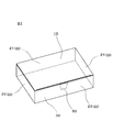
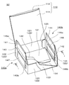
- FIG. 1 is a perspective view showing an appearance before opening of a packaging box
- FIG. 2 is a perspective view of a state in which articles are stored in the packaging box
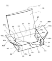
- 3 is a perspective view of the packaging box with the side flaps opened
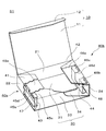
- FIG. 4 is a perspective view of the packaging box with the side flaps closed
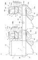
- FIG. 5 is a sectional view of the packaging box (II in FIG. 2).
- FIG. 6 is a development view of the box forming substrate of the packaging box
- FIG. 7 is a front view of the packaging box in a folded state.
- FIGS. 8 to 10 relate to another embodiment of the present invention
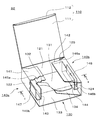
- FIG. 8 is a perspective view of the packaging box with the side flap opened
- FIG. 9 is the packaging box with the side flap closed.
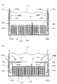
- 10 is a sectional view of the packaging box ((a) a sectional view taken along line ii in FIG. 8, (b) is a sectional view taken along line ii-ii in FIG. 9)
- FIG. 11 is a box formation of the packaging box. It is an expanded view of a board
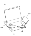
- FIG. 12 is a perspective view of a state in which a side flap of a packaging box is opened according to still another embodiment of the present invention.
- the packaging box S1 of this example is a rectangular parallelepiped box for storing articles.
- the packaging box S1 is a substantially hollow rectangular shape comprising a lid 10 and four side plates 21, 22, 23, 24. A shape body 20 and a bottom 30 are provided.
- the packaging box S1 is configured such that an article can be taken in and out from the upper surface by opening the lid 10.
- buffer portions 40a and 40b in which buffer spaces for reducing the impact on the articles stored in the package box S1 are formed inside a pair of opposite side surfaces of the package box S1 (FIG. 4). reference).
- the body portion is configured by connecting four substantially rectangular side plates 21, 22, 23, and 24, and the side plate 21 and the side plate 23, and the side plate 22 and the side plate 24 are arranged substantially in parallel. Yes.
- the cover plate 11 is formed in a substantially rectangular shape, and is connected to the upper side of the side plate 21 so as to be bent.
- the insertion flap 12 is connected to the end side opposite to the side connected to the side plate 21 so as to be bent.
- the lid 10 is fixed to the state shown in FIG. 1 by inserting the insertion flap 12 into the inside of the side plate 23.
- the bottom 30 is formed by combining the bottom flaps 31, 32, 33, 34 connected to the lower side of the side plates 21, 22, 23, 24 constituting the body 20.
- the side plate 21 is connected to the side plate 22 and the side plate 24 on both the left and right sides, and the lid plate 11 is connected to the upper side and the bottom flap 31 is connected to the lower side so as to be bent.
- the side plate 23 is disposed substantially parallel to the side plate 21 with a predetermined interval, and is connected to the side plate 22 and the side plate 24 on both the left and right sides.
- a bottom flap 33 is connected to the lower side of the side plate 23 so that it can be bent.
- the side plate 22 and the side plate 24 are disposed substantially in parallel with a predetermined interval, and are connected to the side plate 21 and the side plate 23 on the left and right sides, respectively.
- the buffer portion 40 a includes a side flap 41, a first support plate 45 a as a support plate that is continuously provided from the side flap 41 and adhered to the side flap 41, and a first support plate 45 a A buffer plate 43 extending through the second support plate 45 b and the third support plate 45 c, and an adhesive piece 47 extending from the buffer plate 43 and adhered to the bottom plate 32.
- the buffer portion 40a has a side flap 41 connected to the lid portion 10 side (the upper end in the present embodiment) of the side plate 22 toward the inside of the body portion, and a side (the main side) of the side flap 41 connected to the side plate 22.
- a first support plate 45a connected to the side facing the upper end in the embodiment (in this embodiment, the end facing the end to which the side plate 22 is connected) and attached to the side flap;
- a second support plate 45b connected to the lower side (lower end in the present embodiment) of the first support plate 45a, and a lower support (lower end in the present embodiment) of the second support plate 45b and buffered.
- the second support plate 45b is not attached to the side plate 22 and the side flap 41, and is provided to absorb the thickness of the side flap 41 and the first support plate 45a when the side flap 41 is closed. Also, when the side flap 41 is opened, the second support plate 45b absorbs the thickness of the side flap 41 and the first support plate 45a, so that the side flap 41 is easy to open.
- the third support plate 45c is installed on the side plate 22 and the buffer plate 43, and is disposed so as to be substantially horizontal. Therefore, since a space is maintained between the side plate 22 and the buffer plate 43, the packaging box S1 has a function of mitigating external impact.
- the third support plate 45 c and the sticking plate 47 are formed substantially parallel to each other, and the sticking piece 47 is stuck to the inner surface of the bottom flap 32.
- the second support plate 45b, the third support plate 45c, and the buffer plate 43 are formed with notches 45d.
- the cutout portion 45d is formed so as to be cut out from a substantially central portion of the upper end of the buffer plate 43 toward the third support plate 45c.
- the notch portion 45d when the content stored in the packaging box S1 is taken out, it also functions as a thimble hole, making it easier to take out the content. If the area of the notch 45d is reduced, the strength of the buffer 40a is improved, and if the area of the notch 45d is increased, the content can be easily taken out. Therefore, the area of the notch 45d is necessary. It can be changed as appropriate depending on the buffer capacity (strength of the buffer 40a) and workability.
- the buffer capacity can be adjusted by changing the area of the notch 45d, the control of the buffer capacity can be made easier. That is, when the flexibility of the buffer plate 43 is desired to be increased, the notch portion 45d may be formed larger, and when the rigidity of the buffer plate 43 is desired to be improved, the notch portion 45d is formed smaller ( Or it is not provided). Therefore, the packaging box S1 can arbitrarily control the size of the buffer plate 43 and the size of the notch 45d, and depends on the hardness (breakability) and weight of the tablet 4 accommodated therein. Thus, an appropriate buffer capacity can be provided.
- the connection part c of the support plate 45c, the connection part d of the third support plate 45c and the buffer plate 43, and the connection part e of the buffer plate 43 and the sticking piece 47 are formed to be bendable.
- the connection portion a is subjected to half-cutting processing so as to be easily folded, and perforations are formed in the connection portions b to e so as to be easily bent.
- the sticking piece 47 connected to the buffer plate 43 is stuck to the bottom flap 32 and is formed with substantially the same width as the third support plate 45c disposed horizontally. And the edge of the sticking piece 47 is arrange
- FIG. 5 shows a cross-sectional view taken along the line II of FIG. Since the buffer portions 40a and 40b formed at the two locations are symmetrical with each other, for convenience, one buffer portion 40a side formed inside the side plate 22 will be described as a representative.
- the side plate 22 and the buffer plate 43 are formed at substantially the same height and are arranged so as to be substantially parallel with a predetermined distance therebetween.
- the third support plate 45c and the sticking piece 47 are Each is arranged in parallel. These are connected via bendable connection portions b to e. Therefore, in the packaging box S1, the buffer space surrounded by the buffer plate 43, the side plate 22, the third support plate 45c, and the sticking piece 47 forms a parallelogram. Therefore, since the buffer plate 43 is supported only by the upper end and the lower end, it has appropriate flexibility.
- the buffer plate 43 is configured by a piece of paper continuously provided from the side flap 41, the size of the buffer plate 43 and the side flap 41 can be arbitrarily set independently of each other. Therefore, the area of the buffer plate 43 can be increased, and as a result, the packaging box S1 can obtain a sufficient buffer capacity.
- the area of the side flap 41 is not dependent on the area of the buffer plate 43 and can secure a large area, in the packaging box S1, the space between the lid portion 10 and the trunk portion 20 is placed in the box. It is possible to prevent foreign matters from entering.
- the buffer part 40a folds the bottom flaps 31, 32, 33, 34 of the packaging box S1 as shown in FIG. 7, the angle between the sticking piece 47 and the third support plate 45c (the angle with respect to the side plate 22). By changing, it can be deformed into a flat shape.
- the buffer plate 43 can be expanded and contracted inward of the trunk portion according to the folding operation of the bottom flap 32. This is because the angle of the sticking piece 47 changes in accordance with the change in the angle of the bottom flap 32, and the buffer plate 43 moves in the inner and outer directions of the trunk portion 20.
- a pillow packaged product (pillow) 2 in which tablets 4 are enclosed will be described as an example of an article stored in the packaging box S1.
- five pillows 2 encapsulated in a state where a plurality of PTP packaging sheets 3 supporting tablets 4 are stacked are stored side by side in parallel.
- the PTP packaging sheet 3 in the pillow 2 is disposed so as to be parallel to the buffer plate 43.
- the packaging box S1 of the present invention has a particularly high buffering capacity against the tablet 4 which is vulnerable to impact and has high hardness but is easily broken.
- the packaging box S1 of the present invention is suitable for packaging a plurality of tablets 4 that are easily broken against impact. Furthermore, it is also suitable for tablets having low hardness and fragile properties such as orally disintegrating tablets.
- the pillow 2 is stored in a state where there is no gap in contact with the adjacent pillow 2 and the buffer portions 40a and 40b, and is stored so as not to move in the packaging box S1. Therefore, the distance between the buffer part 40a and the buffer part 40b depends on the size (horizontal width) of the pillow 2 to be packaged, and is formed to be approximately an integral multiple of the horizontal width of the pillow 2.
- a sheet 51 such as a note or advertisement may be inserted between the pillows 2 as shown in FIG.
- the buffer plates 43 and 44 provided on the side surface side expand and contract in accordance with the folding operation of the bottom flaps 32 and 34 to form buffer spaces between the side plates 22 and 24 for protecting internal articles from impact, respectively. Therefore, the buffer space is configured only when the buffer plates 43 and 44 are bulged. In this manner, when the buffer plates 43 and 44 are bulged, a buffering effect can be obtained against an external impact. Specifically, the shock energy can be absorbed by the elastic deformation and plastic deformation of the buffer plates 43 and 44 and the side plates 22 and 24 to effectively prevent the article from being damaged.
- the strength of the buffer plates 43 and 44 can be adjusted by adjusting the shape and size of the notches 45d and 46d to obtain an optimal buffering effect, and can be stably held from the side surface direction of the article.
- the buffer plates 43 and 44 are in close contact with the pillow 2 which is the content without providing a gap, but the notches 45d and 46d also function as thimbles, so the pillow 2 can be easily taken out. Since the expansion and contraction of the buffer plates 43 and 44 can be made to follow the folding operation of the bottom flaps 32 and 34, the packaging operation and the taking in and out operation of the article are facilitated. Therefore, work efficiency can be increased and packaging costs can be reduced. Further, when the packaging box S1 is folded, the packaging box S1 can be folded into a flat shape as shown in FIG. 7, so that a necessary space can be kept small when the packaging box S1 is stored or transported.
- the packaging box S1 of the present invention is not configured to form the buffer portions 40a and 40b by cutting out the side flaps 41 and 42, the area of the side flaps 41 and 42 can be secured large. Therefore, the effect which prevents a foreign material from entering between the cover part 10 and the trunk
- FIG. 6 shows a development view of the box forming substrate 1 for assembling the packaging box S1.
- the packaging box S1 shown in this example is formed by folding and assembling a box forming substrate 1 made of a single sheet formed by punching blank paper (blank sheet).
- the box forming substrate 1 is formed of a paper material having moderate flexibility and moderate strength for forming a casing.
- four side plates 21, 22, 23, and 24 constituting the trunk portion 20 are connected in series in the trunk direction, and the other lid portion 10, the bottom portion 30 and the buffer portion are provided at the edge portions of the side plates.
- the constituent pieces forming 40a and 40b are connected.
- the side plate 21 is connected to the side plate 22 on one end side in the longitudinal direction and to the sticking piece 25 on the other end side. Further, the lid plate 11 is connected to one end side in the height direction, and the bottom flap 31 is connected to the other end side.
- the insertion flap 12 is connected to the cover plate 11, and the sticking piece 31 a is connected to the bottom flap 31.
- the side plate 22 connected to one end side of the side plate 21 has a side plate 23 connected to the other end side, and a series of constituent pieces forming the buffer portion 40a connected to one end side in the height direction.
- a bottom flap 32 is connected to the other end of the base plate.
- the side plate 23 connected to one end side of the side plate 22 has a side plate 24 connected to the other end side, and a cut line 50 is formed so as to cut out one end side in the height direction, and the other end side in the height direction is formed.
- the bottom flap 33 is connected.
- the tear line 50 defines an opening portion fixed by the cover plate 11 and an adhesive tape when the cover plate 11 of the packaging box S1 is closed, and is formed by fine perforations.
- a sticking piece 33 a is connected to the bottom flap 33.
- the other end side of the side plate 24 connected to one end side of the side plate 23 is a free end.
- a series of component pieces forming the buffer portion 40b is connected to one end side in the height direction, and a bottom flap 34 is connected to the other end side in the height direction.
- each said component piece is connected via the broken line f, respectively.
- a series of constituent pieces forming the buffer portion 40a includes a side flap 41, a first support plate 45a, a second support plate 45b, a third support plate 45c, a buffer plate 43, and a sticking piece 47 from the side plate 22 side.
- These connection portions a to e are perforated (or half-cut) and easily bent. Then, the connection portions a, d, and e are bent inwardly, and the connection portions b and c are bent so as to be valley-folded, and the sticking piece 47 is stuck to the inner surface of the bottom flap 32.
- the second support plate 45b, the third support plate 45c, and the buffer plate 43 are formed with cut lines for forming a notch portion 45d formed in the vicinity of the center portion.
- the buffer surface strength and the buffer effect of the buffer 40a can be adjusted.
- the bottom part 30 is comprised by assembling the bottom flaps 31, 32, 33, and 34. As shown in FIG.
- the box forming substrate 1 cut out from the blank paper (blank sheet) by the blade mold is first assembled with the buffer portions 40a and 40b.
- the connecting portion a is bent, and then the attaching portion 41a of the side flap 41 and the first support plate 45a are attached (glued) with the connecting portion a being bent.
- a part of the first support plate 45a has an embossed portion 45a 1 is provided with embossed so as to slightly recessed state as viewed from the front, is glued to the embossing unit 45a 1, the side flaps 41 It is easy to stick on and is suitable.
- the outer periphery of the embossed portion 45a 1 is formed inside the outer periphery of the first support plate 45a, and the outer periphery of the embossed portion 45a 1 and the outer periphery of the first support plate 45a are formed apart from each other by a predetermined distance. ing. With such a configuration, when glued, the glue (adhesive) does not protrude from the first support plate 45a, and the appearance can be improved.
- the sticking pieces 47 and 48 of the buffer portions 40a and 40b are bonded to the bottom flaps 32 and 34, respectively.
- the buffer portions 40a and 40b are formed.
- the buffer portions 40a and 40b are three-dimensionally assembled by sticking the sticking portions 47a and 48a of the sticking pieces 47 and 48 to the sticking portions 32b and 34b.
- sticking part 32b, 34b is provided in the surface on the opposite side to the surface with which sticking part 32a, 34a was provided in bottom flaps 32, 34, respectively.
- the sticking pieces 31a and 33a of the bottom flaps 31 and 33 are attached to the sticking portions 32a and 34a of the bottom flaps 32 and 34 while being folded inward.
- the bottom part 30 is formed and it will be in the state before box making.
- the sticking piece 25 connected with the side plate 21 is stuck on the sticking part 24a of the side plate 24.
- FIG. Moreover, the process mentioned above can be performed with an assembly machine.
- the packaging box S1 before box making assembled in this way can be made into a box-making state very easily by pushing the bottom part 30 stuck and folded inside to the outside.
- the packaging box S1 having a buffer structure inside the side plates 22 and 24 can be started up three-dimensionally. Therefore, it is possible to improve the workability and reduce the manufacturing cost, and provide a packaging box S1 that can provide a sufficient buffering effect against an external impact at a low cost and with a simple manufacturing process. can do.
- the assembly process is composed of a folding process and a sticking process along the broken line f, and it is suitable for assembling with a machine because the composition and number of times of folding and sticking are simple. Further, even in the state before the box making, it becomes a flat state without a raised portion, so that space saving at the time of storage can be achieved.
- the box forming substrate 1 does not have the same configuration as described above.
- the buffer portion 40a formed inside the side plate 22 is divided into two buffer portions having different heights, the gap is eliminated even when an article having a stepped shape is stored. be able to.
- the height of the buffer portions 40a and 40b is determined by the length of the buffer plates 43 and 44 and the second support plates 45b and 46b (the height of the buffer plates 43 and 44).
- Two buffer portions 40a and 40b having different heights 43 and 44 may be formed on the side plates 22 and 24, respectively.
- FIG. 2 (Configuration of packaging box S2)
- the structure of packaging box S2 which concerns on other embodiment is demonstrated with reference to FIG. 8, FIG.
- the packaging box S2 of this example is characterized in that it includes buffer portions 140a and 140b different from the packaging box S1 of the above embodiment.
- the description is abbreviate
- the buffer portion 140 a includes a side flap 141, a first support plate 145 a as a support plate that is continuously provided from the side flap 141 and attached to the side flap 141, A buffer plate 143 extending from the support plate 145a and an adhesive piece 147 extending from the buffer plate 143 through the second support plate 145b and attached to the side plate 122 are provided.
- the buffer portion 140a includes a side plate 122, a buffer plate 143 arranged in parallel with the side plate 122 at a predetermined interval, and a side flap connected to the upper end of the side plate 122 (the end portion on the lid portion 110 side).
- 141 a first support plate 145a connected to the upper end of the side flap 141 (the end opposite to the end to which the side plate 122 is connected) and attached to the side flap 141, and the buffer plate 143
- a second support plate 145b connected to the lower end; and an adhesive piece 147 connected to the lower end of the second support plate 145b.
- the buffer plate 143 is connected to the lower end of the first support plate 145a.
- the packaging box S ⁇ b> 2 of the present embodiment is characterized in that the sticking piece 147 is stuck to the inner surface of the side plate 122 instead of the bottom flap 132.
- connection part a between the side flap 141 and the first support plate 145a, the connection part b' between the first support plate 145a and the buffer plate 143, and the buffer plate 143 and the second support plate 145b.
- the connecting portion c ′, the second supporting plate 145b, and the connecting portion d ′ of the sticking piece 147 are formed to be bendable.
- connection part a ′ is half-cut for easy folding, and the connection parts b ′ to d ′ are perforated or chevron-shaped cuts so as to be easily bent. Is formed.
- the sticking piece 147 connected to the buffer plate 143 through the second support plate 145b is stuck to the side plate 122, and is formed to have substantially the same width as the buffer plate 143. Then, the connection portion c ′ between the second support plate 145b and the buffer plate 143 is folded inward and the side flap 141 is closed, so that the buffer portion 140a is formed between the buffer plate 143 and the side plate 122. Is done.
- FIG. 10A shows a cross-sectional view taken along line ii of FIG. 8
- FIG. 10B shows a cross-sectional view taken along line ii-ii of FIG.
- FIG. 10 the state in which the pillow 2 was accommodated is shown for description. Since the buffer portions 140a and 140b formed in two places are symmetrical to each other, for convenience, one buffer portion 140a side formed inside the side plate 122 will be described as a representative.
- the side plate 122 and the buffer plate 143, and the first support plate 145a (side flap 141) and the second support plate 145b are respectively arranged in parallel, and these can be bent connection portions. They are connected via b'-d '. Accordingly, the buffer space surrounded by the buffer plate 143, the side plate 122, the side flap 141, and the second support plate 145b forms a parallelogram, and the first support plate 145a (side flap 141) and By changing the angle of the second support plate 145b, the second support plate 145b can be deformed inwardly of the body portion 120. Therefore, since the buffer plate 143 is supported only by the upper end and the lower end, it has appropriate flexibility.
- the buffer plate 143 is configured by a piece of paper continuously provided from the side flap 141, the size of the buffer plate 143 and the side flap 141 can be arbitrarily set independently of each other. Therefore, the area of the buffer plate 143 can be increased, and as a result, the packaging box S2 can obtain a sufficient buffer capacity.
- the area of the side flap 141 is not dependent on the area of the buffer plate 143 and can secure a large area, in the packaging box S2, the space between the lid portion 110 and the trunk portion 120 is placed in the box. It is possible to prevent foreign matters from entering.
- the buffer plate 143 can be expanded and contracted inward of the trunk portion 120 according to the bending operation of the side flap 141. This is because the angles of the first support plate 145a and the second support plate 145b change according to the change in the angle of the side flap 141, and the buffer plate 43 moves inward and outward of the body portion.
- the buffer space of the buffer portion 140a is formed or folded as the side flap 141 is opened and closed.
- the buffer space of the buffer portion 140a is configured only when the side flap 141 is folded and closed, when the side flap 141 is in an upright state (opened state), the take-out port is wide and the pillow 2 can be easily packed. is there.
- the buffer plate 143 bulges inward and comes into contact with the pillow 2, thereby eliminating the gap between the pillow 2 and the inner surface of the packaging box S2. Further, when the cover plate 11 is folded to close the packaging box S2, the side flap 141 is fixed in a state of being folded inward. Therefore, when the packaging box S2 is closed, the pillow 2 and the inner surface of the packaging box S2 are fixed. It is possible to maintain a state in which there is no void.
- the packaging box S2 of the present embodiment provides the following effects by providing such a buffer structure.
- the buffer plates 143 and 144 provided on the side surfaces expand and contract in accordance with the folding operation of the side flaps 141 and 142 to form buffer spaces between the side plates 122 and 124, respectively, for protecting internal articles from impact. Therefore, the buffer space is configured only when the buffer plates 143 and 144 are bulged.
- the take-out port is wide and the boxing operation is facilitated, and when the buffer plates 143 and 144 are bulged, a buffering effect is obtained against impacts from the outside.
- the impact energy can be absorbed by the elastic deformation and plastic deformation of the buffer plates 143 and 144 and the side plates 122 and 124 to effectively prevent the article from being damaged.
- sticking pieces 147 and 148 that are stuck to the side plate side continuously to the second support plates 145b and 146b are formed, and the sticking pieces 147 and 148 are the second support plates 145b and 146b (more specifically, Since the connecting portions c ′ and d ′) are attached to the side plates 122 and 124 so as to be separated from the bottom portion 30, the assembly of the packaging box can be facilitated. Further, since the expansion and contraction of the buffer plates 143 and 144 can be made to follow the folding operation of the side flaps 141 and 142, the buffer portions 140a and 140b are not easily caught when the articles are taken in and out, and the packaging work and the work in and out of the goods are easy It becomes. Therefore, yield and work efficiency can be increased, and packaging costs can be reduced. It is also suitable for packaging on machines.
- FIG. 11 is a development view of the box forming substrate 1 ′ for assembling the packaging box S2.
- the packaging box S2 shown in this example is formed by folding and assembling a box-forming substrate 1 'made of a single sheet formed by punching blank paper (blank sheet).
- the box forming substrate 1 ′ is formed of a paper material having moderate flexibility and moderate strength for forming a casing.
- the box forming substrate 1 ′ In the box forming substrate 1 ′, four side plates 121, 122, 123, and 124 constituting the body portion 120 are connected in series in the waist direction, and the other lid portion 110, the bottom portion 130, and the buffer are formed at the edge portions of the side plates.
- the component pieces forming the portions 140a and 140b are connected.
- the configuration other than the constituent pieces that form the buffer portions 140 a and 140 b is substantially the same as that of the box forming substrate 1 of the above embodiment, and thus the description thereof is omitted.
- the sticking piece 125 is connected to one end side in the longitudinal direction, but may be connected to the side plate 121.
- the buffer portion 140a and 140b are similar to each other, the buffer portion 140a connected to the side plate 122 will be described for convenience.
- a series of constituent pieces forming the buffer portion 140a are connected to the side flap 141, the first support plate 145a, the buffer plate 143, the second support plate 145b, and the sticking piece 147 from the side plate 122 side.
- Each of the connecting portions a ′ to d ′ is perforated (or half-cut) and is easily bent. Then, the connecting portions a ′, c ′, d ′ are folded inwardly, the connecting portion b ′ is folded in a valley fold, and the sticking piece 147 is stuck on the inner surface of the side plate 122.
- the box forming substrate 1 ′ cut out from the blank paper (blank sheet) by the blade mold is first assembled with the buffer portions 140 a and 140 b.
- the connecting portion a ′ is bent, and then the attaching portion 141a of the side flap 141 and the first support plate 145a are attached (glued) with the connecting portion a ′ bent.
- the sticking pieces 147 and 148 of the buffer portions 140a and 140b are bonded to the side plates 122 and 124, respectively.
- the buffer portions 140a and 140b are formed.
- the buffer portions 140a and 140b are three-dimensionally assembled by sticking the sticking portions 147a and 148a of the sticking pieces 147 and 148 to the sticking portions 122a and 124a.
- the bottom 130 is formed by sticking the sticking pieces 131a and 133a of the bottom flaps 131 and 133 to the sticking parts 132a and 134a of the bottom flaps 132 and 134, respectively, while folding them inward. Become.
- the sticking piece 125 connected to the side plate 124 is stuck to the sticking portion 121 a of the side plate 121.
- formation of buffer part 140a, 140b, sticking of the sticking piece 125, and sticking of the bottom part 130 are performed substantially simultaneously.
- the process mentioned above can be performed with an assembly machine.
- the packaging box S2 before boxing assembled in this way can be made into a box-making state very easily by pushing the bottom part 130 attached and folded inside to the outside.
- the packaging box S2 having the buffer structure inside the side plates 122 and 124 can be raised in a three-dimensional manner by folding and assembling one box-forming substrate 1 ′. Further, the assembly process is constituted by a folding process and a sticking process along the broken line f ′, and the configuration and the number of constituent pieces to be folded and stuck are easy, so that it is suitable for assembly by a machine. Furthermore, since the flat state without the raised portion is obtained even before the box making, it is possible to save space during storage.
- the buffer portions 140a and 140b are flat, so that the contents can be easily put therein.
- the lid plate 111 is closed and the side flaps 141 and 142 are closed, the buffer portions 140a and 140b bulge smoothly and form a buffer space. Therefore, the packaging box S2 has a high buffer effect. It is easy to put in and out the contents while preparing.
- the box forming substrate 1 may not have the same configuration as described above.
- the buffer units 140a and 140b may be divided into a plurality of parts. In this case, for example, if the buffer part 140a formed inside the side plate 122 is divided into two buffer parts having different heights, the gap is eliminated even when an article having a stepped shape is stored. be able to. Specifically, since the height of the buffer portions 140a and 140b is determined depending on the size of the buffer plates 143 and 144, two buffer portions 140a and 140b having different heights of the buffer plates 143 and 144 are provided. What is necessary is just to form in the side plates 122 and 124.
- FIG. 3 (Configuration of packaging box S3)
- the configuration of a packaging box S3 according to still another embodiment (Embodiment 3) will be described with reference to FIG.
- the packaging box S3 of this example is characterized by including buffer portions 240a and 240b different from the packaging box S1 of the above embodiment.
- the description is abbreviate
- the packaging box S3 of the present embodiment is characterized in that the buffer portions 240a and 240b do not have a cutout portion. Yes.
- the buffer portions 240a and 240b having a large buffer capacity can be obtained.
- the applicant of the present application has the packaging box S3 of the present invention according to the configuration of the above-described embodiment (the embodiment of the present invention) and the packaging box S ′ of Patent Document 5 shown in FIG.
- a cushioning effect confirmation test is carried out using a packaging box configured to support the middle part of the cushioning material: comparative product 2) by bending it into a letter shape to make a cut-and-raised piece and connecting and fixing its tip to the side plate. The contents were checked for damage. The test contents and test results are shown below.
- Each article A, B, C is stored as an article containing a pillow and a desiccant (powder desiccant packaged in a bag shape) held on a PTP packaging sheet. Each of the tablets was dropped from the height, and the number of broken tablets was examined.
- -Specimen A Packaging box with a small buffer structure (Comparative Example 1)
- -Specimen B Packaging box provided with an intermediate support in a buffer structure (Comparative Example 2)
- -Specimen C Packaging box with large buffer structure (Example)
- the pillow used was one in which two PTP packaging sheets and a desiccant were enclosed. More specifically, the PTP packaging sheet is enclosed in the pillow in a state where the storage portions (protruding portions) face each other so as to mesh with each other. Further, in one PTP packaging sheet, 14 tablets (7 tablets ⁇ 2 rows) are packaged.
- the desiccant is formed in a flat bag shape, and is stored in the pillow so as to be along the surface side from which the medicine of the PTP packaging sheet is taken out. In addition, the desiccant is enclosed along one PTP packaging sheet among the two PTP packaging sheets.
- each of the test bodies A, B, and C was packed in a box and dropped so that the left-side buffer part was down.
- the pillow is in a state where the desiccant is stored so as to be upward with respect to the dropping direction of the packaging box (that is, a state where the tablet is most easily damaged because a buffering effect by the desiccant cannot be obtained).
- one pillow contains two PTP sheets and a desiccant
- one PTP packaging sheet contains 14 tablets. Is contained.
- Specimen A of Comparative Example 1 has a structure in which a buffer portion is formed inside a side plate portion, but a buffer portion is formed by cutting a part of a side flap, and the area of the buffer plate is small, and the strength of the buffer portion Is relatively weak (low rigidity).
- the test body B of Comparative Example 2 has a configuration in which the intermediate support portion is provided in the buffer portion, and the buffer portion strength is relatively strong (high rigidity).
- the test body C which is an example of the present invention has a large area of the buffer plate as compared with the test body A and is not provided with an intermediate support portion like the test body B.
- the buffer plate has moderate flexibility. Therefore, the specimen C has a configuration in which the strength of the buffer portion is medium (the rigidity is medium) compared to the specimens A and B.
- test specimens A and B of the comparative example are formed so that the inside thereof has the same dimensions as when the buffer portions 240a and 240b of the test specimen C are expanded.
- Other structures and dimensions are the same packaging box as the present invention.
- PTP packaging sheet and tablets used in this test Details of the PTP packaging sheet and tablets used in this test are shown below.
- the results of the tablet drop test used in this test are as follows: The number of broken tablets when dropped with the medicine container (pocket) up was 29 tablets, and the number of broken tablets when dropped with the pocket down was 118 tablets.
- the tablet used in this test has a larger tablet weight than other general tablets. Furthermore, the size of the PTP packaging sheet is also larger than that of other general PTP packaging sheets.
- Results Table 1 shows the number of broken tablets in the drop test for specimens A, B, and C.
- the number of broken tablets is about one-fourth compared to the test body A, and one-third compared to the test body B. Compared to bodies A and B, it was shown that the number of broken tablets was extremely small. Therefore, it was recognized that the test body A (packaging box S3 of the present invention) has an extremely high buffer capacity.
- the product of the present invention has a very high buffering capacity against external impacts as compared with the comparative example. Therefore, compared with the structure of the comparative example, the product of the present invention is not an article with a relatively large weight such as a vial, but has a sufficient flexibility in the buffer portion when a lightweight tablet is packaged. It has the ability. Compared to other general tablets, especially the tablets have higher hardness, and the tablets that are relatively heavy compared to general tablets are more reliably damaged against external impacts. It was confirmed that there was an effect that can be prevented.
- the packaging boxes S1 to S3 of the present invention are not limited to the tablets used in the above-described confirmation test, but the strength of the tablets, from one PTP packaging sheet to a PTP packaging sheet packed with tablets from a height of 150 cm.
- the packaging boxes S1 to S3 of the present invention are also used for tablets whose strength is such that when 10 tablets are dropped, the number of broken tablets is 1 or more (that is, tablets that are vulnerable to external impact). High buffer capacity. Moreover, it has a high buffering capacity even for tablets having a hardness of 9.8 N or more and 110 N (according to a tablet hardness meter manufactured by Schleunigel) or less. Therefore, the packaging foils S1 to S3 of the present invention are particularly preferably used for the above tablets.
- Table 2 below shows examples of tablets (tablets A to G, of which tablets A to F are orally disintegrating tablets) packaged by the packaging boxes S1 to S3 of the present invention.
- the drop test at this time was also evaluated using the drop tester DT-202 (manufactured by Yoshida Seiki) used in the confirmation test.
- the hardness of the tablet shown in Table 2 is a value measured by a tablet hardness meter manufactured by Schleunigel.
- “Upper” in Table 2 is the number of tablet breakage when dropping the PTP packaging sheet containing the tablets (protruded pockets) so that it is upward, and “Lower” is the PTP packaging sheet It is the number of tablet breaks when the tablet is dropped so that the part containing the tablet (protruded pocket part) faces downward.
- the buffer units 40a and 40b (or the buffer units 140a and 140b and the buffer unit 240a, As in 240b), it is not necessary to provide the buffer portion so as to be symmetrical at two locations.
- the buffering portions do not have to be provided at two locations. More specifically, when the pillow 2 has a sufficient cushioning effect on one side by enclosing the desiccant on one side partitioned by the PTP packaging sheet, the cushioning portion is only on one side in the packaging box. It is good also as the provided structure.
- the packaging box having a cushioning function of the present invention can be used as a packaging box for packaging a PTP sheet containing a tablet having a fragile property against an external impact. Compared to a simple tablet, it can be suitably used for a tablet having a relatively large weight.
Landscapes
- Engineering & Computer Science (AREA)
- Mechanical Engineering (AREA)
- Cartons (AREA)
- Buffer Packaging (AREA)
- Packages (AREA)
Abstract
錠剤が収納されたPTPシートを包装する包装用箱であって、十分な緩衝能が得られる緩衝空間を備えた緩衝機能を有する包装用箱を提供する。 包装用箱Sは、一連の側板21,22,23,24を折り曲げて形成された胴部20と、上部に形成された蓋部10と、下部に形成された底部30と、互いに対向する一対の側板22,24の内側に緩衝部40a,40bとを備えている。緩衝部40a,40bは、胴部20の内側に向けて側板22,24から連設されたサイドフラップ41,42と、サイドフラップ41,42から折曲可能に連設されてサイドフラップ41,42に貼着された支持板45a,46aと、支持板45a,46aから延設された緩衝板43,44と、緩衝板43,44から延設され、胴部20または底部30に貼着された貼着片47,48と、を有し、緩衝板43,44は、側板22,24と離間して配設され、可撓性を備えている。
Description
本発明は緩衝機能を有する包装用箱に係り、特に内部に収納された錠剤が外部衝撃によって破損することを防止する緩衝構造を備えた緩衝機能を有する包装用箱に関する。
従来、包装用の紙箱等に壊れやすい錠剤や割れやすいアンプル等の内容物を収納する場合には、内容物を外部衝撃から守るため、紙箱と内容物との空隙に発泡部材やエアーキャップなどの緩衝材が充填されていた。また、内容物の形に合わせて成形された緩衝材からなる成形品に内容物を収めてから、紙箱の中に収納することが行われていた。
このような包装方法では、紙箱とは別体で緩衝材を準備する必要があり、また、包装工程が煩雑化されるため、包装コストがかかるという問題点があった。
そこで、包装箱の内周面に沿って緩衝二重構造を設けた紙製の包装箱が知られている。(例えば、特許文献1~5参照)。
そこで、包装箱の内周面に沿って緩衝二重構造を設けた紙製の包装箱が知られている。(例えば、特許文献1~5参照)。
特許文献1及び2では、包装箱の側板にそれぞれ内壁を形成して二重構造とし、バイアルやアンプルを支持するため、内壁の一部を切り欠いて挿入部を設け、バイアル等のホルダーを備えた構成が開示されている。そして、上記構成の包装箱は、挿入部にバイアル等を嵌合させることにより、バイアル等を外部の衝撃から保護することができる。
特許文献3及び4の緩衝材付き包装箱は、両側面の内周面に沿って板状の緩衝材が設けられたものである。緩衝材は両端部が支持されており、包装箱の側面板との間に所定の緩衝空間を有している。緩衝空間を形成する緩衝材には、中間部の撓みを防止するために中間支持部が設けられている。また、特許文献4の緩衝材付き包装箱の緩衝材の中間支持部は、緩衝材の中間部に切り込みを形成し、この切り込み部をL字状に折り曲げて切り起こし片とし、その先端を側面板に連結固着することにより、緩衝材の中間部を支持するように構成されている。
そして、上記構成の特許文献3及び4の包装箱は、緩衝材によって外部からの衝撃を吸収し、薬剤キット、ガラス製品等の衝撃により破損する虞のあるものを衝撃から保護する。
そして、上記構成の特許文献3及び4の包装箱は、緩衝材によって外部からの衝撃を吸収し、薬剤キット、ガラス製品等の衝撃により破損する虞のあるものを衝撃から保護する。
しかし、上記特許文献1~4は、いずれもバイアル等、一定の強度及び重量を備えたものが収納されるための包装箱に関するものである。したがって、上記特許文献1~4で開示された包装箱を用いても、錠剤を包装する際、十分な緩衝効果を得ることが難しかった。
特許文献1及び2のホルダー付き組立式包装用箱は、箱に設けられたホルダーの部分が底板から成形されているため、箱の寸法に自由度が低く、PTPシートに充てんされた錠剤を収納するには内容物に合ったサイズを設計することが難しい。
また、特許文献3及び4の包装箱に備えられた緩衝材は、薬剤キット等の比較的重量が大きいものを保持する強度を備える必要があることから、緩衝材において中間部の撓みを防止して中間支持部または切り起こし片が備えられている。したがって、薬剤キットよりも軽量である錠剤を収納すると、緩衝材が補強されていて中間部が撓まないため、緩衝材が固すぎて、適当な緩衝効果が得られないという問題点があった。
さらに、特許文献1~4において開示された包装箱は、バイアル等、比較的重量が大きい物品を保持する必要性があることから、一定の剛性を備えるために、緩衝構造の部分が補強されている。したがって、箱全体の構造が複雑となり、箱を成形する際の作業が煩雑になるという問題点があった。
上記問題点に対し、特許文献5では、錠剤を外部衝撃から保護するため、適度な緩衝能を有し、且つ構成が簡単で製造工程を簡易化することができる包装用箱S′が開示されている(図13参照)。
特許文献5の緩衝材付き包装用箱S′は、図13に示すように、サイドフラップ41′,42′の一部を切って形成された緩衝板43′,44′によって、側壁が二重構造になっており、錠剤(より詳細には、錠剤がその内部に包装されたPTPシートを収容したピロー)を外部衝撃から保護するための緩衝能を備えている。緩衝板43′,44′は、上方に備えられたサイドフラップ41′,42′の一部及び第1の支持板45a′,46a′と、側面に貼着された支持板(不図示)とで支持されているため、緩衝板43′,44′の中央部は可撓性を有しており、外部衝撃に弱く壊れやすい錠剤を保護することができる。
しかし、特許文献5の緩衝材付き包装用箱S′は、サイドフラップ41′,42′を構成する部分の台紙を切り欠いて緩衝板43′,44′を形成するため、サイドフラップ41′,42′と緩衝板43′,44′の大きさを両者とも大きく確保することができず、緩衝板43′,44′の大きさが制限される。そして、緩衝板43′,44′の大きさを任意で大きくすることができず、フラップの大きさにより緩衝能を向上させるには改善の余地があった。
したがって、包装用箱において、緩衝板43′,44′の大きさを任意に設定することができ、外部衝撃に対して壊れやすい錠剤に対し、十分に高い緩衝能を備えることが可能な技術が望まれていた。
したがって、包装用箱において、緩衝板43′,44′の大きさを任意に設定することができ、外部衝撃に対して壊れやすい錠剤に対し、十分に高い緩衝能を備えることが可能な技術が望まれていた。
本発明は、上記の問題点に鑑みてなされたものであり、その目的は、錠剤が収納されたPTPシートを包装する包装用箱であって、十分な緩衝能が得られる緩衝空間を備えた緩衝機能を有する包装用箱を提供することにある。
また、本発明の他の目的は、構成が簡単であり、製造工程の簡易化が可能な緩衝機能を有する包装用箱を提供することにある。
また、本発明の他の目的は、構成が簡単であり、製造工程の簡易化が可能な緩衝機能を有する包装用箱を提供することにある。
前記課題は、本発明の包装用箱によれば、1枚の箱形成基板を折り曲げ組み立てて形成されると共に、錠剤が収納されたPTP包装シートを包装する包装用箱であって、一連の側板を所定位置で折り曲げて略中空矩形状に連結して形成された胴部と、該胴部に連結されて上部に形成された蓋部と、前記胴部に連結されて下部に形成された底部と、互いに対向する一対の前記側板の内側の少なくとも一方に形成された緩衝部と、を備え、前記緩衝部は、前記胴部の内側に向けて前記側板の前記蓋部側に連結されたサイドフラップと、該サイドフラップの前記側板が連結された側と対向する側に連結されると共に前記サイドフラップに貼着された第1の支持板と、該第1の支持板の下側に連結される第2の支持板と、該第2の支持板の下側に連結されると共に前記緩衝板に連結された第3の支持板と、前記側板と所定間隔で離間して略平行に支持板から延設された可撓性を有する緩衝板と、前記緩衝板から延設され、前記胴部または前記底部に貼着された貼着片と、を備えること、により解決される。
このように、本発明の包装用箱は、互いに対向する側板の少なくとも一方に緩衝部を有しており、緩衝部は、前記胴部の内側に向けて前記側板の前記蓋部側に連結されたサイドフラップと、該サイドフラップの前記側板が連結された側と対向する側に連結されると共に前記サイドフラップに貼着された第1の支持板と、該第1の支持板の下側に連結される第2の支持板と、該第2の支持板の下側に連結されると共に前記緩衝板に連結された第3の支持板と、前記側板と所定間隔で離間して略平行に支持板から延設された可撓性を有する緩衝板と、前記緩衝板から延設され、前記胴部または前記底部に貼着された貼着片と、を備えている。
このような構成により、本発明では、側面側に設けられた緩衝板が側板に対して離間して配設されている。したがって、緩衝板が側板に対して支持板と貼着板とによってのみ支持される構成である(すなわち、二点においてのみ支持される)ため、緩衝板は十分な可撓性を備えている。
さらに、緩衝板は、サイドフラップの一部を切って形成する構成ではなく、サイドフラップの側板と所定間隔で離間して略平行に支持板から延設された可撓性を有し、折曲可能に連設された構成であるため、サイドフラップの大きさに依存せず、緩衝板を任意の大きさに形成することができる。その結果、緩衝板を十分に大きくすることが可能となり、緩衝板がより高い可撓性を備えることができる。
また、十分な可撓性を備えた緩衝板を有するため、本発明の包装用箱は、錠剤が収納されたPTPシートに対し、十分な緩衝機能が得られる緩衝空間を備えている。
そして、本発明の包装用箱は、1枚の箱形成基板を折り曲げて形成するため、構成が簡単であり、製造工程が極めて簡易化されている。したがって、本発明の包装用箱は、廉価に製造することができる。
さらに、サイドフラップと緩衝板の大きさを互いに独立に設定することができるため、緩衝板を大きく形成しても、サイドフラップを十分に大きく形成することができる。したがって、蓋部と胴部との間をサイドフラップによって覆うことができるため、蓋部と胴部との間から箱内へ異物が侵入するのを効果的に防ぐことができる。
このような構成により、本発明では、側面側に設けられた緩衝板が側板に対して離間して配設されている。したがって、緩衝板が側板に対して支持板と貼着板とによってのみ支持される構成である(すなわち、二点においてのみ支持される)ため、緩衝板は十分な可撓性を備えている。
さらに、緩衝板は、サイドフラップの一部を切って形成する構成ではなく、サイドフラップの側板と所定間隔で離間して略平行に支持板から延設された可撓性を有し、折曲可能に連設された構成であるため、サイドフラップの大きさに依存せず、緩衝板を任意の大きさに形成することができる。その結果、緩衝板を十分に大きくすることが可能となり、緩衝板がより高い可撓性を備えることができる。
また、十分な可撓性を備えた緩衝板を有するため、本発明の包装用箱は、錠剤が収納されたPTPシートに対し、十分な緩衝機能が得られる緩衝空間を備えている。
そして、本発明の包装用箱は、1枚の箱形成基板を折り曲げて形成するため、構成が簡単であり、製造工程が極めて簡易化されている。したがって、本発明の包装用箱は、廉価に製造することができる。
さらに、サイドフラップと緩衝板の大きさを互いに独立に設定することができるため、緩衝板を大きく形成しても、サイドフラップを十分に大きく形成することができる。したがって、蓋部と胴部との間をサイドフラップによって覆うことができるため、蓋部と胴部との間から箱内へ異物が侵入するのを効果的に防ぐことができる。
このとき、前記緩衝板は、上方に開口した切り欠き部が形成されてなると好適である。
このように、緩衝板は上方に開口した切り欠き部を備えているため、より緩衝板が撓みやすく、その結果、緩衝能の高い緩衝部を備えた包装用箱とすることができる。
このように、緩衝板は上方に開口した切り欠き部を備えているため、より緩衝板が撓みやすく、その結果、緩衝能の高い緩衝部を備えた包装用箱とすることができる。
また、本発明の包装用箱は、前記錠剤が、1枚の前記PTP包装シート内に前記錠剤を包装した状態の前記PTP包装シートを、高さ150cmの高さから10枚落下させたとき、前記錠剤の破損数が1錠以上となる強度を有するときにおいて好適に用いられる。
このように、本発明の包装用箱は、緩衝能が極めて高い緩衝部を備えているため、上記のように破損しやすい錠剤の包装用途に対して、特に好適に用いられる。
このように、本発明の包装用箱は、緩衝能が極めて高い緩衝部を備えているため、上記のように破損しやすい錠剤の包装用途に対して、特に好適に用いられる。
さらに、本発明の包装用箱は、前記錠剤が、硬度が9.8N以上、110N以下の錠剤であるときに特に好適に用いられる。
このように、本発明の包装用箱は、緩衝能が高い緩衝部を備えているため、硬度が所定数値以下の壊れやすい錠剤の包装用として、特に好適である。
PTP包装に適用可能な錠剤の強度、すなわち、通常のPTP包装のカバーシートから製剤を押し出して取り出すことが可能な錠剤の強度の目安として、錠剤の縦方向の硬度が挙げられる。その硬度は錠剤の大きさ、形状により異なるが、例えば直径約8.0mmの時、約9.8N、また、直径約10.0mmの時、約14.7N、さらに、直径約12.0mmの時、約19.6N以上が好適である。
このように、本発明の包装用箱は、緩衝能が高い緩衝部を備えているため、硬度が所定数値以下の壊れやすい錠剤の包装用として、特に好適である。
PTP包装に適用可能な錠剤の強度、すなわち、通常のPTP包装のカバーシートから製剤を押し出して取り出すことが可能な錠剤の強度の目安として、錠剤の縦方向の硬度が挙げられる。その硬度は錠剤の大きさ、形状により異なるが、例えば直径約8.0mmの時、約9.8N、また、直径約10.0mmの時、約14.7N、さらに、直径約12.0mmの時、約19.6N以上が好適である。
さらにまた、本発明の包装用箱は、前記錠剤が、口腔内崩壊錠であるときに特に好適に用いられる。
本発明の緩衝機能を有する包装用箱は、大きな緩衝部を確保することができ、緩衝部に備えられた緩衝板が十分に撓むことができるため、緩衝能が高い。したがって、内部に収納するPTPシートに包装された錠剤を、外部衝撃から効果的に保護することができる。その結果、外部衝撃に対して壊れやすい性質を有する錠剤に対して、特に好適に用いることができる。
また、本発明の包装用箱は、1枚の箱形成基板を折り曲げ組み立てることにより、側板の内側に緩衝構造を有する包装用箱を形成することができる。したがって、外部からの衝撃に対して十分な緩衝効果が得られる包装用箱を、低コストで、かつ、簡易な製造工程により提供することができる。
また、本発明の包装用箱は、1枚の箱形成基板を折り曲げ組み立てることにより、側板の内側に緩衝構造を有する包装用箱を形成することができる。したがって、外部からの衝撃に対して十分な緩衝効果が得られる包装用箱を、低コストで、かつ、簡易な製造工程により提供することができる。
S′,S1,S2,S3 包装用箱
a~e,a′~d′ 接続部
f,f′ 折れ線
1,1′ 箱形成基板
2 ピロー
3 PTP包装シート
4 錠剤
10,110 蓋部
11,111 蓋板
12,112 差込みフラップ
20,120 胴部
21,22,23,24,121,122,123,124 側板
25,31a,33a,47,48,125,131a,133a,147,148 貼着片
24a,32a,32b,34a,34b,41a,42a,47a,48a,121a,122a,124a,132a,134a,141a,142a,147a,148a, 貼着部
30,130 底部
31,32,33,34,131,132,133,134 底フラップ
40a,40b,140a,140b,240a,240b 緩衝部
41′,42′,41,42,141,142 サイドフラップ
43′,44′,43,44,143,144,243,244 緩衝板
45a′,46a′,45a,46a,145a,146a 第1の支持板(支持板)
45a1,46a1 エンボス部
45b,46b,145b,146b 第2の支持板
45c,46c 第3の支持板
45d,46d 切り欠き部
50,150 切取線
51 シート
a~e,a′~d′ 接続部
f,f′ 折れ線
1,1′ 箱形成基板
2 ピロー
3 PTP包装シート
4 錠剤
10,110 蓋部
11,111 蓋板
12,112 差込みフラップ
20,120 胴部
21,22,23,24,121,122,123,124 側板
25,31a,33a,47,48,125,131a,133a,147,148 貼着片
24a,32a,32b,34a,34b,41a,42a,47a,48a,121a,122a,124a,132a,134a,141a,142a,147a,148a, 貼着部
30,130 底部
31,32,33,34,131,132,133,134 底フラップ
40a,40b,140a,140b,240a,240b 緩衝部
41′,42′,41,42,141,142 サイドフラップ
43′,44′,43,44,143,144,243,244 緩衝板
45a′,46a′,45a,46a,145a,146a 第1の支持板(支持板)
45a1,46a1 エンボス部
45b,46b,145b,146b 第2の支持板
45c,46c 第3の支持板
45d,46d 切り欠き部
50,150 切取線
51 シート
以下、本発明の一実施形態について、図を参照して説明する。なお、以下に説明する部材、配置等は、本発明を限定するものではなく、本発明の趣旨に沿って各種改変することができることは勿論である。
図1~図7は本発明の一実施形態に係るものであり、図1は包装用箱の開封前の外観を示す斜視図、図2は包装用箱に物品を収納した状態の斜視図、図3は包装用箱のサイドフラップを開いた状態の斜視図、図4は包装用箱のサイドフラップを閉じた状態の斜視図、図5は包装用箱の断面図(図2のI-I断面図)、図6は包装用箱の箱形成基板の展開図、図7は包装用箱を折り畳んだ状態の正面図である。
また、図8~図10は本発明の他の実施形態に係るものであり、図8は包装用箱のサイドフラップを開いた状態の斜視図、図9は包装用箱のサイドフラップを閉じた状態の斜視図、図10は包装用箱の断面図((a)図8のi-i断面図、(b)は図9のii-ii断面図)、図11は包装用箱の箱形成基板の展開図である。
さらに図12は、本発明のさらに他の実施形態に係るものであり、包装用箱のサイドフラップを開いた状態の斜視図である。
図1~図7は本発明の一実施形態に係るものであり、図1は包装用箱の開封前の外観を示す斜視図、図2は包装用箱に物品を収納した状態の斜視図、図3は包装用箱のサイドフラップを開いた状態の斜視図、図4は包装用箱のサイドフラップを閉じた状態の斜視図、図5は包装用箱の断面図(図2のI-I断面図)、図6は包装用箱の箱形成基板の展開図、図7は包装用箱を折り畳んだ状態の正面図である。
また、図8~図10は本発明の他の実施形態に係るものであり、図8は包装用箱のサイドフラップを開いた状態の斜視図、図9は包装用箱のサイドフラップを閉じた状態の斜視図、図10は包装用箱の断面図((a)図8のi-i断面図、(b)は図9のii-ii断面図)、図11は包装用箱の箱形成基板の展開図である。
さらに図12は、本発明のさらに他の実施形態に係るものであり、包装用箱のサイドフラップを開いた状態の斜視図である。
[実施形態1]
(包装用箱S1の構成)
本例の包装用箱S1は、物品を収納するための直方体状の箱であり、図1に示すように、蓋部10と、4枚の側板21,22,23,24からなる略中空矩形状の胴部20と、底部30と、を備えている。
この包装用箱S1は、蓋部10を開封することにより上面から物品を出し入れすることができるように構成されている。
また、包装用箱S1の対向する一対の側面内側には包装用箱S1に収納する物品への衝撃を緩和するための緩衝空間が形成された緩衝部40a,40bが設けられている(図4参照)。
(包装用箱S1の構成)
本例の包装用箱S1は、物品を収納するための直方体状の箱であり、図1に示すように、蓋部10と、4枚の側板21,22,23,24からなる略中空矩形状の胴部20と、底部30と、を備えている。
この包装用箱S1は、蓋部10を開封することにより上面から物品を出し入れすることができるように構成されている。
また、包装用箱S1の対向する一対の側面内側には包装用箱S1に収納する物品への衝撃を緩和するための緩衝空間が形成された緩衝部40a,40bが設けられている(図4参照)。
胴部は、略長方形の4枚の側板21,22,23,24を連結することで構成されており、側板21と側板23、及び、側板22と側板24はそれぞれ略平行に配設されている。
蓋板11は、略長方形状に形成され、側板21の上部側に屈曲可能に連接されている。また、図2、図3に示すように、側板21に接続された側とは逆側の端部側には差込みフラップ12が屈曲可能に連接されている。閉箱状態では、この差込みフラップ12を側板23の内側に差込むことによって蓋部10が図1の状態に固定される。
底部30は、胴部20を構成する側板21,22,23,24の下部側に連結された底フラップ31,32,33,34を互いに組み合わせることにより形成される。
蓋板11は、略長方形状に形成され、側板21の上部側に屈曲可能に連接されている。また、図2、図3に示すように、側板21に接続された側とは逆側の端部側には差込みフラップ12が屈曲可能に連接されている。閉箱状態では、この差込みフラップ12を側板23の内側に差込むことによって蓋部10が図1の状態に固定される。
底部30は、胴部20を構成する側板21,22,23,24の下部側に連結された底フラップ31,32,33,34を互いに組み合わせることにより形成される。
ここで、上述した4枚の側板21,22,23,24と他の構成片との接続について説明する。
側板21は、左右の両側で側板22と側板24に接続されており、上部側には蓋板11が、下部側には底フラップ31がそれぞれ屈曲可能に連結されている。
側板23は、所定の間隔を有して側板21と略平行に配設され、左右の両側で側板22と側板24に接続されている。側板23の下部側には底フラップ33がそれぞれ屈曲可能に連結されている。
側板22と側板24は、所定の間隔を有して略平行に配設され、左右両側でそれぞれ側板21と側板23に接続されている。側板22と側板24の上部側には、緩衝部40a,40bと連結されたサイドフラップ41,42が、下部側には底フラップ32,34がそれぞれ屈曲可能に連結されている。そして、側板22と側板24の内側に緩衝部40a,40bが形成される。
側板21は、左右の両側で側板22と側板24に接続されており、上部側には蓋板11が、下部側には底フラップ31がそれぞれ屈曲可能に連結されている。
側板23は、所定の間隔を有して側板21と略平行に配設され、左右の両側で側板22と側板24に接続されている。側板23の下部側には底フラップ33がそれぞれ屈曲可能に連結されている。
側板22と側板24は、所定の間隔を有して略平行に配設され、左右両側でそれぞれ側板21と側板23に接続されている。側板22と側板24の上部側には、緩衝部40a,40bと連結されたサイドフラップ41,42が、下部側には底フラップ32,34がそれぞれ屈曲可能に連結されている。そして、側板22と側板24の内側に緩衝部40a,40bが形成される。
次に、本例の緩衝部40a,40bの特徴的な構成について説明する。
2箇所に形成された緩衝部40a,40bは互いに対称であるので、便宜上、側板22の内側に形成された一方側の緩衝部40a側を代表として説明する。
図4に示すように、緩衝部40aは、サイドフラップ41と、サイドフラップ41から連設されてサイドフラップ41に貼着された支持板としての第1の支持板45aと、支持板45aから第2の支持板45b及び第3の支持板45cを介して延設された緩衝板43と、緩衝板43から延設されて底板32に貼着された貼着片47を備えている。
2箇所に形成された緩衝部40a,40bは互いに対称であるので、便宜上、側板22の内側に形成された一方側の緩衝部40a側を代表として説明する。
図4に示すように、緩衝部40aは、サイドフラップ41と、サイドフラップ41から連設されてサイドフラップ41に貼着された支持板としての第1の支持板45aと、支持板45aから第2の支持板45b及び第3の支持板45cを介して延設された緩衝板43と、緩衝板43から延設されて底板32に貼着された貼着片47を備えている。
すなわち、緩衝部40aは、胴部の内側に向けて側板22の蓋部10側(本実施形態では上端)に連結されたサイドフラップ41と、サイドフラップ41の側板22が連結された側(本実施形態では上端)と対向する側(本実施形態では側板22が連結された端部と対向する側の端部)に連結されると共にサイドフラップに貼着された第1の支持板45aと、第1の支持板45aの下側(本実施形態では下端)に連結される第2の支持板45bと、第2の支持板45bの下側(本実施形態では下端)に連結されると共に緩衝板43に連結された第3の支持板45cと、側板22と所定間隔で離間して略平行に第3の支持板45cから延設された可撓性を有する緩衝板43と、緩衝板43から延設され、胴部20または底部30に貼着された貼着片47と、を備えている。
第2の支持板45bは側板22及びサイドフラップ41に対して貼着されておらず、サイドフラップ41を閉じるときにサイドフラップ41及び第1の支持板45aの厚みを吸収するために備えられる。また、サイドフラップ41を開く際にも、第2の支持板45bがサイドフラップ41及び第1の支持板45aの厚みを吸収するため、サイドフラップ41が開きやすい。
また、第3の支持板45cは側板22と緩衝板43とに架設され、略水平になるように配設されている。したがって、側板22と緩衝板43との間に空間が保持されるため、包装用箱S1は、外部からの衝撃を緩和する機能を有する。第3の支持板45c及び貼着板47は互いに略平行に形成されており、貼着片47は、底フラップ32の内面に貼着される。
そして、第2の支持板45b,第3の支持板45c、緩衝版43には、切り欠き部45dが形成されている。切り欠き部45dは、具体的には、緩衝板43の上端の略中央部から第3の支持板45cに向かって切り欠かれるように形成される。
また、切り欠き部45dを備えることにより、包装用箱S1の内部に収納される内容物を取り出す際、指ぬき穴としての機能も果たすため、内容物を取り出しやすくなる。
なお、切り欠き部45dの面積を小さくすると緩衝部40aの強度が向上し、切り欠き部45dの面積を大きくすると、内容物の取り出し性が向上するため、切り欠き部45dの面積は、必要な緩衝能力(緩衝部40aの強度)と作業性に依存して適宜変更可能である。
なお、切り欠き部45dの面積を小さくすると緩衝部40aの強度が向上し、切り欠き部45dの面積を大きくすると、内容物の取り出し性が向上するため、切り欠き部45dの面積は、必要な緩衝能力(緩衝部40aの強度)と作業性に依存して適宜変更可能である。
このように、切り欠き部45dの面積を変更することにより、緩衝能を調節することができるため、より緩衝能の制御を容易にすることができる。すなわち、緩衝板43の可撓性を高めたい場合には、切り欠き部45dを大きく形成すればよいし、緩衝板43の剛性を向上させたい場合には、切り欠き部45dを小さく形成する(或いは設けない)とよい。
したがって、包装用箱S1は、緩衝板43の大きさ、及び切り欠き部45dの大きさを任意に制御可能であり、内部に収納される錠剤4の硬度(壊れやすさ)・重量に依存して、適切な緩衝能を備えることができる。
したがって、包装用箱S1は、緩衝板43の大きさ、及び切り欠き部45dの大きさを任意に制御可能であり、内部に収納される錠剤4の硬度(壊れやすさ)・重量に依存して、適切な緩衝能を備えることができる。
図6に示すように、サイドフラップ41と第1の支持板45aの接続部a、第1の支持板45aと第2の支持板45bの接続部b、第2の支持板45bと第3の支持板45cの接続部c、第3の支持板45cと緩衝板43の接続部d、緩衝板43と貼着片47の接続部eは屈曲可能に形成されている。
また、接続部aは、折り返しやすくするため、半切掛(ハーフカット)加工が施されており、接続部b~eにはそれぞれ屈曲させやすいように、ミシン目が形成されている。
また、接続部aは、折り返しやすくするため、半切掛(ハーフカット)加工が施されており、接続部b~eにはそれぞれ屈曲させやすいように、ミシン目が形成されている。
緩衝板43に接続された貼着片47は、底フラップ32に貼着され、水平に配設される第3の支持板45cと略同じ幅で形成されている。そして、貼着片47の縁端は底フラップ32と側板22との境界部分、すなわち折れ線fに沿って(または平行に)配設される。したがって、貼着片47と第3の支持板45cとが略平行に配設され、且つ、緩衝板43と側板22とが略平行に配設されることにより、緩衝板43と側板22との間に緩衝部40aが形成される。
(緩衝部40a,40bの作用効果)
次に、緩衝部40a,40bの作用効果について説明する。図5には図2のI-I断面図を示した。2箇所に形成された緩衝部40a,40bは互いに対称であるので、便宜上、側板22の内側に形成された一方側の緩衝部40a側を代表として説明する。
次に、緩衝部40a,40bの作用効果について説明する。図5には図2のI-I断面図を示した。2箇所に形成された緩衝部40a,40bは互いに対称であるので、便宜上、側板22の内側に形成された一方側の緩衝部40a側を代表として説明する。
緩衝部40aにおいて、側板22と緩衝板43は互いに略同じ高さに形成され、所定距離離間して略平行となるように配設されており、第3の支持板45cと貼着片47はそれぞれ平行に配設されている。また、これらは屈曲可能な接続部b~eを介して接続されている。したがって、包装用箱S1において、緩衝板43,側板22,第3の支持板45c,及び貼着片47によって囲まれて形成された緩衝空間は平行四辺形を形成する。したがって、緩衝板43は、上端及び下端によってのみ支持されるので、適当な可撓性を有する。
また、緩衝板43は、サイドフラップ41から連設された紙片によって構成されているため、緩衝板43とサイドフラップ41は互いに独立してその大きさを任意に設定することができる。したがって、緩衝板43の面積を大きく形成することができ、その結果、包装用箱S1は、十分な緩衝能を得ることができる。
また、サイドフラップ41の面積もまた、緩衝板43の面積に依存せず、大きな面積を確保することができるため、包装用箱S1において、蓋部10と胴部20との間から箱内に異物が入り込んでしまうことを防止することができる。
そして、緩衝部40aは、包装用箱S1の底フラップ31,32,33,34を図7のように折り畳むとき、貼着片47と第3の支持板45cの角度(側板22に対する角度)を変えることによって、偏平状に変形することができる。
このように、貼着片47は底フラップ32に貼着されて一体に動くことから、底フラップ32の折曲動作にしたがって緩衝板43は胴部の内方に膨縮させることができる。これは、底フラップ32の角度の変化にしたがって貼着片47の角度が変化し、緩衝板43を胴部20の内外方向に移動するためである。
このように、貼着片47は底フラップ32に貼着されて一体に動くことから、底フラップ32の折曲動作にしたがって緩衝板43は胴部の内方に膨縮させることができる。これは、底フラップ32の角度の変化にしたがって貼着片47の角度が変化し、緩衝板43を胴部20の内外方向に移動するためである。
本実施形態では、包装用箱S1に収納する物品として、錠剤4を封入したピロー包装品(ピロー)2を例にとって説明する。図2、図5に示すように、錠剤4が支持されたPTP包装シート3を複数枚重ねた状態で封入したピロー2を5つ縦置きに並列に並べて収納される。このとき、ピロー2内のPTP包装シート3は緩衝板43と平行になるように配置される。
また、ピロー2に封入された錠剤4は、後述するように、衝撃に弱く、壊れやすい性質を有するものがある。このように、衝撃に対して脆弱性があり、高硬度ではあるが、割れやすい錠剤4に対し、本発明の包装用箱S1は、特に高い緩衝能を保持する。このように、本発明の包装用箱S1は、衝撃に対して割れやすい錠剤4を複数包装する際に好適である。
さらに、口腔内崩壊錠のように、硬度が低く壊れやすい性質を有する錠剤にも好適である。
さらに、口腔内崩壊錠のように、硬度が低く壊れやすい性質を有する錠剤にも好適である。
そしてこのとき、ピロー2は、互いに隣り合うピロー2及び緩衝部40a,40bに当接して空隙がない状態で収納され、包装用箱S1内で移動することがないように収納される。したがって、緩衝部40aと緩衝部40bとの間の距離は、包装されるピロー2の大きさ(横幅)に依存し、ピロー2の横幅のほぼ整数倍となるように形成される。
また、さらに緩衝効果を高めるため、ピロー2の間には、図2に示すように、注意書きや広告等のシート51を挿入してもよい。
また、さらに緩衝効果を高めるため、ピロー2の間には、図2に示すように、注意書きや広告等のシート51を挿入してもよい。
本発明では、このような緩衝構造を設けることにより、以下のような効果を奏する。
側面側に設けられた緩衝板43,44が底フラップ32,34の折曲動作にしたがって膨縮して、内部の物品を衝撃から保護する緩衝空間を側板22,24との間にそれぞれ形成するため、緩衝板43,44を膨出させた状態で初めて緩衝空間が構成される。そして、このように、緩衝板43,44を膨出させた状態では外部からの衝撃に対して緩衝効果を得ることができる。具体的には、緩衝板43,44及び側板22,24の弾性変形及び塑性変形によって衝撃エネルギーを吸収して物品の破損を効果的に防止することができる。
側面側に設けられた緩衝板43,44が底フラップ32,34の折曲動作にしたがって膨縮して、内部の物品を衝撃から保護する緩衝空間を側板22,24との間にそれぞれ形成するため、緩衝板43,44を膨出させた状態で初めて緩衝空間が構成される。そして、このように、緩衝板43,44を膨出させた状態では外部からの衝撃に対して緩衝効果を得ることができる。具体的には、緩衝板43,44及び側板22,24の弾性変形及び塑性変形によって衝撃エネルギーを吸収して物品の破損を効果的に防止することができる。
さらにまた、切り欠き部45d,46dの形状及び大きさにより緩衝板43,44の強度を調整して最適な緩衝効果を得ることができ、物品の側面方向から安定して保持することができる。このとき、緩衝板43,44は内容物であるピロー2に対して空隙を備えることなく密接するが、切り欠き部45d,46dが指ぬきとしての機能も果たすため、ピロー2を取り出しやすくなる。
緩衝板43,44の膨縮を底フラップ32,34の折曲動作に従わせることができるため、包装作業や物品の出し入れ作業が容易となる。よって、作業効率が上昇し、包装コストを低減化させることができる。
また、包装用箱S1を折り畳んだ際、図7のように、平面状に折り畳むことができるため、包装用箱S1の収納時や運搬時、必要なスペースを小さく抑えることができる。
緩衝板43,44の膨縮を底フラップ32,34の折曲動作に従わせることができるため、包装作業や物品の出し入れ作業が容易となる。よって、作業効率が上昇し、包装コストを低減化させることができる。
また、包装用箱S1を折り畳んだ際、図7のように、平面状に折り畳むことができるため、包装用箱S1の収納時や運搬時、必要なスペースを小さく抑えることができる。
なお、本発明の包装用箱S1は、サイドフラップ41,42を切り欠くことにより緩衝部40a,40bを形成する構成ではないため、サイドフラップ41,42の面積を大きく確保することができる。したがって、包装用箱S1の箱側方から蓋部10と胴部20との間に異物が入り込むのを防止する効果が高い。
(包装用箱S1の組み立て)
次に、本例の包装用箱S1を組み立てるための基板の構成について説明する。図6に包装用箱S1を組み立てるための箱形成基板1の展開図を示す。本例に示す包装用箱S1は空白紙(ブランクシート)を打ち抜いて形成した一枚紙からなる箱形成基板1を折り曲げ組み立てることにより形成されている。なお、箱形成基板1は、適度な可撓性を備えると共に、筺体を形成するために適度な強度を備えた紙材から形成されている。
箱形成基板1は、胴部20を構成する4枚の側板21,22,23,24が胴回り方向に一連に接続され、各側板の縁端部分に他の蓋部10、底部30や緩衝部40a,40bを形成する構成片が接続されている。
次に、本例の包装用箱S1を組み立てるための基板の構成について説明する。図6に包装用箱S1を組み立てるための箱形成基板1の展開図を示す。本例に示す包装用箱S1は空白紙(ブランクシート)を打ち抜いて形成した一枚紙からなる箱形成基板1を折り曲げ組み立てることにより形成されている。なお、箱形成基板1は、適度な可撓性を備えると共に、筺体を形成するために適度な強度を備えた紙材から形成されている。
箱形成基板1は、胴部20を構成する4枚の側板21,22,23,24が胴回り方向に一連に接続され、各側板の縁端部分に他の蓋部10、底部30や緩衝部40a,40bを形成する構成片が接続されている。
ここで、箱形成基板1状態での、4枚の側板21,22,23,24と他の構成片との接続について説明する。
側板21は、長手方向の一端側で側板22と、他端側では貼着片25と接続されている。また、高さ方向の一端側で蓋板11と、他端側では底フラップ31と接続されている。蓋板11には差込みフラップ12が、底フラップ31には貼着片31aが接続されている。
側板21は、長手方向の一端側で側板22と、他端側では貼着片25と接続されている。また、高さ方向の一端側で蓋板11と、他端側では底フラップ31と接続されている。蓋板11には差込みフラップ12が、底フラップ31には貼着片31aが接続されている。
側板21の一端側に接続された側板22は、他端側に側板23が接続され、高さ方向の一端側には緩衝部40aを形成する一連の構成片が接続されており、高さ方向の他端側には底フラップ32が接続されている。
側板22の一端側に接続された側板23は、他端側に側板24が接続され、高さ方向の一端側を切り欠くように切取線50が形成されており、高さ方向の他端側には底フラップ33が接続されている。切取線50は、包装用箱S1の蓋板11を閉めたときに、蓋板11と接着テープ等により固定される開封口部分を区画するものであり、細かいミシン目によって形成されている。また、底フラップ33には貼着片33aが接続されている。
側板22の一端側に接続された側板23は、他端側に側板24が接続され、高さ方向の一端側を切り欠くように切取線50が形成されており、高さ方向の他端側には底フラップ33が接続されている。切取線50は、包装用箱S1の蓋板11を閉めたときに、蓋板11と接着テープ等により固定される開封口部分を区画するものであり、細かいミシン目によって形成されている。また、底フラップ33には貼着片33aが接続されている。
側板23の一端側に接続された側板24の他端側は自由端となっている。高さ方向の一端側には緩衝部40bを形成する一連の構成片が接続されており、高さ方向の他端側には底フラップ34が接続されている。
なお、上記各構成片はそれぞれ、折れ線fを介して接続されている。
なお、上記各構成片はそれぞれ、折れ線fを介して接続されている。
緩衝部40a,40bは互いに同様であるので、便宜上、側板22に接続された緩衝部40aについて説明する。
緩衝部40aを形成する一連の構成片は、側板22側からサイドフラップ41、第1の支持板45a、第2の支持板45b、第3の支持板45c、緩衝板43、貼着片47と接続されており、これらの接続部a~eにはそれぞれミシン目(またはハーフカット加工)が施され折曲げが容易に構成されている。そして、接続部a,d,eが内側に向かって山折り、接続部b,cが谷折りになるように折曲され、貼着片47が底フラップ32の内面に貼着される。
また、第2の支持板45b、第3の支持板45c、緩衝板43には、中央部付近に形成された切り欠き部45dを形成するための切り込み線が形成されている。この切り欠き部45dの大きさを調整することにより、緩衝部40aの緩衝面強度や緩衝効果を調整することができる。
そして、底部30は、底フラップ31,32,33,34を組み立てることにより構成される。
緩衝部40aを形成する一連の構成片は、側板22側からサイドフラップ41、第1の支持板45a、第2の支持板45b、第3の支持板45c、緩衝板43、貼着片47と接続されており、これらの接続部a~eにはそれぞれミシン目(またはハーフカット加工)が施され折曲げが容易に構成されている。そして、接続部a,d,eが内側に向かって山折り、接続部b,cが谷折りになるように折曲され、貼着片47が底フラップ32の内面に貼着される。
また、第2の支持板45b、第3の支持板45c、緩衝板43には、中央部付近に形成された切り欠き部45dを形成するための切り込み線が形成されている。この切り欠き部45dの大きさを調整することにより、緩衝部40aの緩衝面強度や緩衝効果を調整することができる。
そして、底部30は、底フラップ31,32,33,34を組み立てることにより構成される。
続いて、箱形成基板1の組み立て方法について説明する。
刃型によって空白紙(ブランクシート)から切り抜かれた箱形成基板1は、まず、緩衝部40a,40bが組み立てられる。
接続部aを折り曲げ、次いで、接続部aを折り曲げた状態でサイドフラップ41の貼着部41aと第1の支持板45aとを貼着(糊付け)する。このとき、第1の支持板45aの一部が、表面から見て若干凹んだ状態となるようにエンボス加工を施してエンボス部45a1を設け、そのエンボス部45a1に糊付けすると、サイドフラップ41に貼着しやすく、好適である。なお、緩衝部40b側についても同様である。
刃型によって空白紙(ブランクシート)から切り抜かれた箱形成基板1は、まず、緩衝部40a,40bが組み立てられる。
接続部aを折り曲げ、次いで、接続部aを折り曲げた状態でサイドフラップ41の貼着部41aと第1の支持板45aとを貼着(糊付け)する。このとき、第1の支持板45aの一部が、表面から見て若干凹んだ状態となるようにエンボス加工を施してエンボス部45a1を設け、そのエンボス部45a1に糊付けすると、サイドフラップ41に貼着しやすく、好適である。なお、緩衝部40b側についても同様である。
エンボス部45a1は、その外周が第1の支持板45aの外周よりも内側に形成されており、エンボス部45a1の外周と第1の支持板45aの外周とは所定距離離間して形成されている。このような構成により、糊付けした際、糊(接着剤)が第1の支持板45aからはみ出すことがなく、外観性を向上させることができる。
このように、胴部20の内側に緩衝部40aを形成する一連の連続片を折り曲げた状態とした後、緩衝部40a,40bの貼着片47,48がそれぞれ底フラップ32,34に接着されることにより、緩衝部40a,40bが形成される。具体的には、貼着部32b,34bに対して貼着片47,48の貼着部47a,48aが貼り付けられることにより、緩衝部40a,40bが立体的に組み立てられる。なお、貼着部32b,34bは、それぞれ底フラップ32,34において、貼着部32a,34aが備えられた面とは反対側の面に設けられる。
そして、緩衝部40a,40bが形成された状態とした後、底フラップ31,33の貼着片31a,33aをそれぞれ底フラップ32,34の貼着部32a,34aにそれぞれ内側に折り畳みながら貼着することで底部30が形成され製箱前の状態となる。
また、底部30が形成された状態とした後、側板21に連結された貼着片25が側板24の貼着部24aに貼着される。また、上述した工程は組み立て機械にて行うことができる。
このように組み立てられた製箱前の包装用箱S1は、貼着されて内側に折り畳まれた底部30を外側へ押し込むことによって極めて容易に製箱状態とすることができる。
また、底部30が形成された状態とした後、側板21に連結された貼着片25が側板24の貼着部24aに貼着される。また、上述した工程は組み立て機械にて行うことができる。
このように組み立てられた製箱前の包装用箱S1は、貼着されて内側に折り畳まれた底部30を外側へ押し込むことによって極めて容易に製箱状態とすることができる。
1枚の箱形成基板1を折り曲げ組み立てることにより、側板22,24の内側に緩衝構造を有する包装用箱S1を立体的に立ち上げることができる。したがって、作業性の向上と製造コストの低減を図ることができると共に、外部からの衝撃に対して十分な緩衝効果が得られる包装用箱S1を、低コストで、かつ、簡易な製造工程により提供することができる。
また、組み立て工程は、折れ線fに沿っての折り曲げ工程と、貼着工程によって構成され、折り曲げ、貼着する構成片の構成や回数も平易であることから機械での組み立てに適しており、また、製箱前の状態においても隆起部分のない平らな状態となることから保存の際の省スペース化を図ることができる。
なお、本例のような包装用箱S1を組み立てるためには、箱形成基板1が上記と同一の構成でなくても可能である。
例えば、緩衝部40a,40bを、切り欠き部45d,46dを介して複数に分割して構成してもよい。この場合、例えば、側板22の内側に形成した緩衝部40aを高さの異なる2つの緩衝部に分割するように構成とすれば、段差のある形状を有する物品を収納した場合にも間隙をなくすことができる。具体的には、緩衝部40a,40bの高さは、緩衝板43,44及び第2の支持板45b,46bの長さ(緩衝板43,44の高さ)で決定されるため、緩衝板43,44の高さの異なる2つの緩衝部40a,40bを側板22,24に形成すればよい。
例えば、緩衝部40a,40bを、切り欠き部45d,46dを介して複数に分割して構成してもよい。この場合、例えば、側板22の内側に形成した緩衝部40aを高さの異なる2つの緩衝部に分割するように構成とすれば、段差のある形状を有する物品を収納した場合にも間隙をなくすことができる。具体的には、緩衝部40a,40bの高さは、緩衝板43,44及び第2の支持板45b,46bの長さ(緩衝板43,44の高さ)で決定されるため、緩衝板43,44の高さの異なる2つの緩衝部40a,40bを側板22,24に形成すればよい。
[実施形態2]
(包装用箱S2の構成)
次に、他の実施形態(実施形態2)に係る包装用箱S2の構成について、図8、図9を参照して説明する。
本例の包装用箱S2は、上記実施形態の包装用箱S1とは異なる緩衝部140a,140bを備えている点を特徴とする。なお、その他の構成は、上記実施形態の包装用箱S1と共通するため、その説明を省略する。
(包装用箱S2の構成)
次に、他の実施形態(実施形態2)に係る包装用箱S2の構成について、図8、図9を参照して説明する。
本例の包装用箱S2は、上記実施形態の包装用箱S1とは異なる緩衝部140a,140bを備えている点を特徴とする。なお、その他の構成は、上記実施形態の包装用箱S1と共通するため、その説明を省略する。
本実施形態の包装用箱S2において、対向する一対の側面内側には包装用箱S2に収納する物品への衝撃を緩和するための緩衝空間が形成された緩衝部140a,140bが設けられている。2箇所に形成された緩衝部140a,140bは互いに対称であるので、便宜上、側板122の内側に形成された一方側の緩衝部140a側を代表として説明する。
図8、9に示すように、緩衝部140aは、サイドフラップ141と、サイドフラップ141から連設されてサイドフラップ141に貼着された支持板としての第1の支持板145aと、第1の支持板145aから延設された緩衝板143と、緩衝板143から第2の支持板145bを介して延設されて側板122に貼着された貼着片147を備えている。
すなわち、緩衝部140aは、側板122と、側板122と所定の間隔を有して平行に配置された緩衝板143と、側板122の上端(蓋部110側の端部)に連結されたサイドフラップ141と、サイドフラップ141の上端(側板122が連結された端部と対向する側の端部)に連結されると共にサイドフラップ141に貼着された第1の支持板145aと、緩衝板143の下端に連結された第2の支持板145bと、第2の支持板145bの下端に連結された貼着片147と、を備えている。なお、緩衝板143は、第1の支持板145aの下端に連結されている。
図8に示すように、サイドフラップ141を開いた状態では、緩衝板143の上端部が、サイドフラップ141に重なるように配設されており、サイドフラップ141と、第1の支持板145a,緩衝板143,第2の支持板145bとは平面状になるように、貼着片147が側板122の内面に貼着される。このように、本実施形態の包装用箱S2は、貼着片147が底フラップ132ではなく、側板122の内面に貼着されていることを特徴とする。
一方、図9に示すように、サイドフラップ141を閉じた状態とすると、サイドフラップ141と第2の支持板145bとが略水平に保持され、且つ側板122と緩衝板143とが所定距離離間して略平行に配設されるため、緩衝部140aにおいて緩衝空間を形成する。この構成により、側板122と緩衝板143との間に空間が保持されるため、包装用箱S2は、外部からの衝撃を緩和する機能を有する。
図11に示すように、サイドフラップ141と第1の支持板145aの接続部a′、第1の支持板145aと緩衝板143の接続部b′、緩衝板143と第2の支持板145bの接続部c′、第2の支持板145bと貼着片147の接続部d′は屈曲可能に形成されている。
また、接続部a′は、折り返しやすくするため、半切掛(ハーフカット)加工が施されており、接続部b′~d′にはそれぞれ屈曲させやすいように、ミシン目または、山型の切り込みが形成されている。
また、接続部a′は、折り返しやすくするため、半切掛(ハーフカット)加工が施されており、接続部b′~d′にはそれぞれ屈曲させやすいように、ミシン目または、山型の切り込みが形成されている。
第2の支持板145bを介して緩衝板143に接続された貼着片147は、側板122に貼着され、緩衝板143と略同じ幅で形成されている。そして、第2の支持板145bと緩衝板143との接続部c′が内側に向かって山折りされ、サイドフラップ141を閉じることにより、緩衝板143と側板122との間に緩衝部140aが形成される。
(緩衝部140a,140bの作用効果)
次に、緩衝部140a,140bの作用効果について説明する。図10(a)には図8のi-i断面図、図10(b)には図9のii-ii断面図を示した。なお、図10には、説明のため、ピロー2が収納された状態を示す。2箇所に形成された緩衝部140a,140bは互いに対称であるので、便宜上、側板122の内側に形成された一方側の緩衝部140a側を代表として説明する。
次に、緩衝部140a,140bの作用効果について説明する。図10(a)には図8のi-i断面図、図10(b)には図9のii-ii断面図を示した。なお、図10には、説明のため、ピロー2が収納された状態を示す。2箇所に形成された緩衝部140a,140bは互いに対称であるので、便宜上、側板122の内側に形成された一方側の緩衝部140a側を代表として説明する。
緩衝部140aにおいて、側板122と緩衝板143、及び第1の支持板145a(サイドフラップ141)と第2の支持板145bはそれぞれ平行に配設されており、また、これらは屈曲可能な接続部b′~d′を介して接続されている。したがって、緩衝板143,側板122,サイドフラップ141,及び第2の支持板145bとによって囲まれて形成された緩衝空間は平行四辺形を形成し、第1の支持板145a(サイドフラップ141)と第2の支持板145bの角度を変えることによって胴部120の内側方向に変形することができる。したがって、緩衝板143は、上端及び下端によってのみ支持されるので、適当な可撓性を有する。
また、緩衝板143は、サイドフラップ141から連設された紙片によって構成されているため、緩衝板143とサイドフラップ141は互いに独立してその大きさを任意に設定することができる。したがって、緩衝板143の面積を大きく形成することができ、その結果、包装用箱S2は、十分な緩衝能を得ることができる。
また、サイドフラップ141の面積もまた、緩衝板143の面積に依存せず、大きな面積を確保することができるため、包装用箱S2において、蓋部110と胴部120との間から箱内に異物が入り込んでしまうことを防止することができる。
さらに、サイドフラップ141は第1の支持板145aと一体に貼着されていることから、サイドフラップ141の折曲動作にしたがって緩衝板143は胴部120の内方に膨縮させることができる。これは、サイドフラップ141の角度の変化にしたがって第1の支持板145a及び第2の支持板145bの角度が変化し、緩衝板43を胴部の内外方向に移動するためである。
このように、本実施形態の包装用箱S2においては、サイドフラップ141の開閉に伴って、緩衝部140aの緩衝空間が形成されたり、折り畳まれたりする。
そして、サイドフラップ141を折り曲げ、閉じた状態で初めて緩衝部140aの緩衝空間が構成されるため、サイドフラップ141を立てた状態(開いた状態)では取り出し口が広くピロー2の箱詰め作業が容易である。
そして、サイドフラップ141を折り曲げ、閉じた状態で初めて緩衝部140aの緩衝空間が構成されるため、サイドフラップ141を立てた状態(開いた状態)では取り出し口が広くピロー2の箱詰め作業が容易である。
サイドフラップ141を内側方向に折り曲げると、緩衝板143が内側へ膨出してピロー2に当接し、ピロー2と包装用箱S2の内面との空隙をなくすことができる。さらに、包装用箱S2を閉じるために蓋板11を折り曲げるとサイドフラップ141が内側に折り曲げられた状態で固定されるため、包装用箱S2を閉じた状態では、ピロー2と包装用箱S2内面との空隙をなくした状態を保持することができる。
本実施形態の包装用箱S2では、このような緩衝構造を設けることにより、以下のような効果を奏する。
側面側に設けられた緩衝板143,144がサイドフラップ141,142の折曲動作にしたがって膨縮して、内部の物品を衝撃から保護する緩衝空間を側板122,124との間にそれぞれ形成するため、緩衝板143,144を膨出させた状態で初めて緩衝空間が構成される。緩衝板143,144を収縮させた状態では取り出し口が広く箱詰め作業が容易となり、緩衝板143,144を膨出させた状態では外部からの衝撃に対して緩衝効果が得られる。具体的には、緩衝板143,144及び側板122,124の弾性変形及び塑性変形によって衝撃エネルギーを吸収して物品の破損を効果的に防止することができる。
側面側に設けられた緩衝板143,144がサイドフラップ141,142の折曲動作にしたがって膨縮して、内部の物品を衝撃から保護する緩衝空間を側板122,124との間にそれぞれ形成するため、緩衝板143,144を膨出させた状態で初めて緩衝空間が構成される。緩衝板143,144を収縮させた状態では取り出し口が広く箱詰め作業が容易となり、緩衝板143,144を膨出させた状態では外部からの衝撃に対して緩衝効果が得られる。具体的には、緩衝板143,144及び側板122,124の弾性変形及び塑性変形によって衝撃エネルギーを吸収して物品の破損を効果的に防止することができる。
また、第2の支持板145b,146bに連続して側板側に貼着される貼着片147,148が形成され、貼着片147,148は第2の支持板145b,146b(より具体的には、接続部c′,d′)が底部30と離れるように側板122,124に貼着されるため包装用箱の組み立てを容易にすることができる。
さらに、緩衝板143,144の膨縮をサイドフラップ141,142の折曲動作に従わせることができるため、物品の出し入れ時に緩衝部140a,140bが引っ掛かりにくく、包装作業や物品の出し入れ作業が容易となる。よって、歩留まり及び作業効率が上昇し、包装コストを低減化させることができる。また、機械での包装にも適している。
さらに、緩衝板143,144の膨縮をサイドフラップ141,142の折曲動作に従わせることができるため、物品の出し入れ時に緩衝部140a,140bが引っ掛かりにくく、包装作業や物品の出し入れ作業が容易となる。よって、歩留まり及び作業効率が上昇し、包装コストを低減化させることができる。また、機械での包装にも適している。
(包装用箱S2の組み立て)
次に、本例の包装用箱S2を組み立てるための基板の構成について説明する。図11に包装用箱S2を組み立てるための箱形成基板1′の展開図を示す。本例に示す包装用箱S2は空白紙(ブランクシート)を打ち抜いて形成した一枚紙からなる箱形成基板1′を折り曲げ組み立てることにより形成されている。なお、箱形成基板1′は、適度な可撓性を備えると共に、筺体を形成するために適度な強度を備えた紙材から形成されている。
次に、本例の包装用箱S2を組み立てるための基板の構成について説明する。図11に包装用箱S2を組み立てるための箱形成基板1′の展開図を示す。本例に示す包装用箱S2は空白紙(ブランクシート)を打ち抜いて形成した一枚紙からなる箱形成基板1′を折り曲げ組み立てることにより形成されている。なお、箱形成基板1′は、適度な可撓性を備えると共に、筺体を形成するために適度な強度を備えた紙材から形成されている。
箱形成基板1′は、胴部120を構成する4枚の側板121,122,123,124が胴回り方向に一連に接続され、各側板の縁端部分に他の蓋部110、底部130や緩衝部140a,140bを形成する構成片が接続されている。
本実施形態の箱形成基板1′において、緩衝部140a,140bを形成する構成片以外の構成は、上記実施形態の箱形成基板1とほぼ同様であるため、その説明を省略する。なお、側板124において、長手方向の一端側に貼着片125が連結されているが、側板121に連結されていても良い。
緩衝部140a,140bは互いに同様であるので、便宜上、側板122に接続された緩衝部140aについて説明する。
緩衝部140aを形成する一連の構成片は、側板122側からサイドフラップ141、第1の支持板145a、緩衝板143、第2の支持板145b、貼着片147と接続されており、これらの接続部a′~d′にはそれぞれミシン目(またはハーフカット加工)が施され折曲げが容易に構成されている。そして、接続部a′,c′,d′が内側に向かって山折り、接続部b′が谷折りに折曲され、貼着片147が側板122の内面に貼着される。
緩衝部140aを形成する一連の構成片は、側板122側からサイドフラップ141、第1の支持板145a、緩衝板143、第2の支持板145b、貼着片147と接続されており、これらの接続部a′~d′にはそれぞれミシン目(またはハーフカット加工)が施され折曲げが容易に構成されている。そして、接続部a′,c′,d′が内側に向かって山折り、接続部b′が谷折りに折曲され、貼着片147が側板122の内面に貼着される。
続いて、箱形成基板1′の組み立て方法について説明する。
刃型によって空白紙(ブランクシート)から切り抜かれた箱形成基板1′は、まず、緩衝部140a,140bが組み立てられる。
接続部a′を折り曲げ、次いで、接続部a′を折り曲げた状態でサイドフラップ141の貼着部141aと第1の支持板145aとを貼着(糊付け)する。なお、緩衝部140b側についても同様である。
刃型によって空白紙(ブランクシート)から切り抜かれた箱形成基板1′は、まず、緩衝部140a,140bが組み立てられる。
接続部a′を折り曲げ、次いで、接続部a′を折り曲げた状態でサイドフラップ141の貼着部141aと第1の支持板145aとを貼着(糊付け)する。なお、緩衝部140b側についても同様である。
このように、胴部120の内側に緩衝部140aを形成する一連の連続片を折り曲げた状態とした後、緩衝部140a,140bの貼着片147,148がそれぞれ側板122,124に接着されることにより、緩衝部140a,140bが形成される。具体的には、貼着部122a,124aに対して貼着片147,148の貼着部147a,148aが貼り付けられることにより、緩衝部140a,140bが立体的に組み立てられる。一方、底フラップ131,133の貼着片131a,133aをそれぞれ底フラップ132,134の貼着部132a,134aにそれぞれ内側に折り畳みながら貼着することで底部130が形成され製箱前の状態となる。更に、側板124に連結された貼着片125が側板121の貼着部121aに貼着される。なお、緩衝部140a,140bの形成と貼着片125の貼着と底部130の貼着はほぼ同時に行われる。また、上述した工程は組み立て機械にて行うことができる。
このように組み立てられた製箱前の包装用箱S2は、貼着されて内側に折り畳まれた底部130を外側へ押し込むことによって極めて容易に製箱状態とすることができる。
このように組み立てられた製箱前の包装用箱S2は、貼着されて内側に折り畳まれた底部130を外側へ押し込むことによって極めて容易に製箱状態とすることができる。
上記のように、1枚の箱形成基板1′を折り曲げ組み立てることにより、側板122,124の内側に緩衝構造を有する包装用箱S2を立体的に立ち上げることができる。
また、組み立て工程は、折れ線f′に沿っての折り曲げ工程と、貼着工程によって構成され、折り曲げ、貼着する構成片の構成や回数も平易であることから機械での組み立てに適している。
さらに、製箱前の状態においても隆起部分のない偏平な状態となることから保存の際の省スペース化を図ることができる。
また、組み立て工程は、折れ線f′に沿っての折り曲げ工程と、貼着工程によって構成され、折り曲げ、貼着する構成片の構成や回数も平易であることから機械での組み立てに適している。
さらに、製箱前の状態においても隆起部分のない偏平な状態となることから保存の際の省スペース化を図ることができる。
さらにまた、サイドフラップ141,142が開かれた状態であると、緩衝部140a,140bが平面状となるため、内容物を入れやすい。一方、蓋板111を閉じて、サイドフラップ141,142を閉じた状態とすると、緩衝部140a,140bとがスムーズに膨出し、緩衝空間を形成するため、包装用箱S2は、高い緩衝効果を備えつつ、内容物の出し入れが容易となる。
なお、本例のような包装用箱S2を組み立てるためには、箱形成基板1が上記と同一の構成でなくても可能である。
例えば、緩衝部140a,140bを、複数に分割して構成してもよい。この場合、例えば、側板122の内側に形成した緩衝部140aを高さの異なる2つの緩衝部に分割するように構成とすれば、段差のある形状を有する物品を収納した場合にも間隙をなくすことができる。具体的には、緩衝部140a,140bの高さは、緩衝板143,144の大きさに依存して決定されるため、緩衝板143,144の高さの異なる2つの緩衝部140a,140bを側板122,124に形成すればよい。
例えば、緩衝部140a,140bを、複数に分割して構成してもよい。この場合、例えば、側板122の内側に形成した緩衝部140aを高さの異なる2つの緩衝部に分割するように構成とすれば、段差のある形状を有する物品を収納した場合にも間隙をなくすことができる。具体的には、緩衝部140a,140bの高さは、緩衝板143,144の大きさに依存して決定されるため、緩衝板143,144の高さの異なる2つの緩衝部140a,140bを側板122,124に形成すればよい。
[実施形態3]
(包装用箱S3の構成)
次に、さらに他の実施形態(実施形態3)に係る包装用箱S3の構成について、図12を参照して説明する。
本例の包装用箱S3は、上記実施形態の包装用箱S1とは異なる緩衝部240a,240bを備えている点を特徴とする。なお、その他の構成は、上記実施形態の包装用箱S1と共通するため、その説明を省略する。
(包装用箱S3の構成)
次に、さらに他の実施形態(実施形態3)に係る包装用箱S3の構成について、図12を参照して説明する。
本例の包装用箱S3は、上記実施形態の包装用箱S1とは異なる緩衝部240a,240bを備えている点を特徴とする。なお、その他の構成は、上記実施形態の包装用箱S1と共通するため、その説明を省略する。
本実施形態の包装用箱S3は、緩衝部40a,40bにおいて切り欠き部45d,46dを備えた包装用箱S1とは異なり、緩衝部240a,240bにおいて切り欠き部を備えていない点を特徴としている。
このように、切り欠き部を設けず、緩衝板243,244を連続した板材によって構成することにより、緩衝能の大きな緩衝部240a,240bとすることができる。
このように、切り欠き部を設けず、緩衝板243,244を連続した板材によって構成することにより、緩衝能の大きな緩衝部240a,240bとすることができる。
なお、包装用箱S3の展開図等は上記実施形態の包装用箱S1と共通であるため、その説明を省略する。
(確認試験)
本願出願人は、上述した実施例の構成による本発明の包装用箱S3(本発明の実施例)と、比較例1としての図13に示す特許文献5の包装用箱S′(サイドフラップの一部を切ることによって緩衝部を形成した包装用箱:比較品1)と、比較例2としての特許文献4の包装用箱(緩衝材の中間部に切り込みを形成し、この切り込み部をL字状に折り曲げて切り起こし片とし、その先端を側面板に連結固着することにより、緩衝材の中間部を支持する構成の包装用箱:比較品2)とを用いて緩衝効果確認試験を行い、内容物の破損状況について確認した。以下に試験内容及び試験結果を示す。
本願出願人は、上述した実施例の構成による本発明の包装用箱S3(本発明の実施例)と、比較例1としての図13に示す特許文献5の包装用箱S′(サイドフラップの一部を切ることによって緩衝部を形成した包装用箱:比較品1)と、比較例2としての特許文献4の包装用箱(緩衝材の中間部に切り込みを形成し、この切り込み部をL字状に折り曲げて切り起こし片とし、その先端を側面板に連結固着することにより、緩衝材の中間部を支持する構成の包装用箱:比較品2)とを用いて緩衝効果確認試験を行い、内容物の破損状況について確認した。以下に試験内容及び試験結果を示す。
(1)試験体
以下に示す試験体A(比較例1),B(比較例2),C(実施例)の3種類を用いた。PTP包装シートに保持された錠剤及び乾燥剤(粉末の乾燥剤が袋状に包装されたもの)が封入されたピローを収納する物品として、各試験体A,B,Cの内部に収め、所定の高さからそれぞれ落下させて、錠剤の破損した数を調べた。
・試験体A:緩衝構造が小さい包装用箱(比較例1)
・試験体B:緩衝構造において中間支持部を備えた包装用箱(比較例2)
・試験体C:緩衝構造が大きい包装用箱(実施例)
以下に示す試験体A(比較例1),B(比較例2),C(実施例)の3種類を用いた。PTP包装シートに保持された錠剤及び乾燥剤(粉末の乾燥剤が袋状に包装されたもの)が封入されたピローを収納する物品として、各試験体A,B,Cの内部に収め、所定の高さからそれぞれ落下させて、錠剤の破損した数を調べた。
・試験体A:緩衝構造が小さい包装用箱(比較例1)
・試験体B:緩衝構造において中間支持部を備えた包装用箱(比較例2)
・試験体C:緩衝構造が大きい包装用箱(実施例)
なお、ピローは、2枚のPTP包装シートと、乾燥剤とが封入されたものを用いた。より詳細には、PTP包装シートは、ピロー内において、収納部(突出した部分)が互いに噛み合うように対向させた状態で封入されている。また、1枚のPTP包装シートにおいて、錠剤は、14錠(7錠×2列)包装されている。乾燥剤は、偏平な袋状に形成されており、PTP包装シートの薬剤が取り出される面側に沿うようにピロー内に収納されている。なお、乾燥剤は、2枚のPTP包装シートのうち、一方のPTP包装シートに沿って封入されている。そして、このピローを5つずつ、フィルム状のバンドによって一纏めにした状態のもの4つを、垂直に立てた状態で(PTP包装シートの薬剤が取り出される面が緩衝板に対して略平行となるようにして)試験体A,B,Cにそれぞれ箱詰めし、それぞれ左側の緩衝部が下になるように落下させた。このとき、ピローは、乾燥剤が包装用箱の落下方向に対して上方となるように収納された状態(すなわち乾燥剤による緩衝効果を得られないため、最も錠剤が破損しやすい状態)としている。
すなわち、包装用箱には20個のピローが収められており、1個のピローには2枚のPTPシートと乾燥剤とが封入されており、1枚のPTP包装シートには14錠の錠剤が収められている。
比較例1の試験体Aは、側板部分の内側に緩衝部が構成されているものの、サイドフラップの一部を切って緩衝部を形成した構造であり、緩衝板の面積が小さく、緩衝部強度が比較的弱い(剛性が低い)構成である。また、比較例2の試験体Bは、緩衝部において中間支持部が備えられており、緩衝部強度が比較的強い(剛性が高い)構成である。これに対し、本発明の実施例である試験体Cは、緩衝板の面積が試験体Aと比較して大きく確保されており、試験体Bのように中間支持部が備えられていないため、緩衝板が適度な可撓性を備えている。したがって試験体Cは、上記試験体A,Bと比較して、緩衝部強度が中程度(剛性が中程度)となる構成である。
また、比較例の試験体A,Bは、その内部が、試験体Cの緩衝部240a,240bの膨出時と同一の寸法となるように形成されている。そして、その他の構造,寸法は本発明品と同様の包装用箱である。
本試験に用いたPTP包装シート及び錠剤の詳細を以下に示す。
・PTP包装シート
シートサイズ:54×147.5mm、包装錠剤数:7錠×2列/枚
・錠剤
錠剤重量:約655mg/錠、硬度:約110N(シュロイニゲル社製錠剤硬度計による)
なお、本試験に用いた錠剤の落下試験(落下高さ150cmとし、PTP包装シート1枚に14錠包装された状態として、PTP包装シートを10枚落下させた場合の破損数)の結果は、薬剤収納部(ポケット)を上にして落下させた場合の錠剤破損数が29錠、ポケットを下にして落下させた場合の錠剤破損数が118錠であった。
・PTP包装シート
シートサイズ:54×147.5mm、包装錠剤数:7錠×2列/枚
・錠剤
錠剤重量:約655mg/錠、硬度:約110N(シュロイニゲル社製錠剤硬度計による)
なお、本試験に用いた錠剤の落下試験(落下高さ150cmとし、PTP包装シート1枚に14錠包装された状態として、PTP包装シートを10枚落下させた場合の破損数)の結果は、薬剤収納部(ポケット)を上にして落下させた場合の錠剤破損数が29錠、ポケットを下にして落下させた場合の錠剤破損数が118錠であった。
上記のように、本試験に用いた錠剤は、一般的な他の錠剤と比較して、錠剤重量が大きいものである。さらに、PTP包装シートの大きさもまた、一般的な他のPTP包装シートと比較して大きいものである。
(2)試験方法
上記PTP包装シートを2枚ずつピローに封入し、ピロー20個を試験体A,B,Cにそれぞれ収納し(計560錠の錠剤を試験体A,B,Cにそれぞれ収納し)、このサンプルについて、落下試験を行った。
落下試験の方法として、落下試験機DT-202(吉田精機製)を用いて包装用箱の左側の緩衝部を下方になるように(ピロー内の乾燥剤が上方となるように)固定治具で保持して所定高さまで持ち上げ、上述した物品の収納状態でそれぞれ鉄板上に落下させて、ピローに封入された錠剤の破損の有無(破損数)を確認した。このとき、同じ試験体(試験体A,B,C)について、それぞれのサンプル数を3として、試験を行った。なお、落下高さは200cmとした。
上記PTP包装シートを2枚ずつピローに封入し、ピロー20個を試験体A,B,Cにそれぞれ収納し(計560錠の錠剤を試験体A,B,Cにそれぞれ収納し)、このサンプルについて、落下試験を行った。
落下試験の方法として、落下試験機DT-202(吉田精機製)を用いて包装用箱の左側の緩衝部を下方になるように(ピロー内の乾燥剤が上方となるように)固定治具で保持して所定高さまで持ち上げ、上述した物品の収納状態でそれぞれ鉄板上に落下させて、ピローに封入された錠剤の破損の有無(破損数)を確認した。このとき、同じ試験体(試験体A,B,C)について、それぞれのサンプル数を3として、試験を行った。なお、落下高さは200cmとした。
(3)結果
表1に試験体A,B,Cについての落下試験での破損錠剤数を示す。
表1に試験体A,B,Cについての落下試験での破損錠剤数を示す。

表1に示すように、本発明品に相当する試験体Cでは、破損錠剤数が試験体Aと比較して約4分の1、試験体Bと比較して3分の1であり、試験体A,Bと比較して、破損錠剤数が極めて少ないことが示された。したがって、試験体A(本発明の包装用箱S3)が、極めて高い緩衝能を保持していることが認められた。
(4)考察
上記結果によれば、本発明品は比較例と比較して外部衝撃に対する緩衝能が極めて高いと言える。したがって、比較例の構成と比較して本発明品は、バイアル等の比較的重量が大きい物品ではなく、軽量な錠剤を包装した際、緩衝部において十分な可撓性を備えることから、高い緩衝能を備えている。そして、他の一般的な錠剤と比較して、特に、錠剤の中でも硬度が高く、一般的な錠剤と比較して、比較的重量の大きな錠剤に関し、外部からの衝撃に対してより確実に破損を防止することができるという効果を奏することが確認された。
上記結果によれば、本発明品は比較例と比較して外部衝撃に対する緩衝能が極めて高いと言える。したがって、比較例の構成と比較して本発明品は、バイアル等の比較的重量が大きい物品ではなく、軽量な錠剤を包装した際、緩衝部において十分な可撓性を備えることから、高い緩衝能を備えている。そして、他の一般的な錠剤と比較して、特に、錠剤の中でも硬度が高く、一般的な錠剤と比較して、比較的重量の大きな錠剤に関し、外部からの衝撃に対してより確実に破損を防止することができるという効果を奏することが確認された。
(その他の錠剤例)
本発明の包装用箱S1~S3は、上記確認試験で用いた錠剤の他、錠剤の強度に関し、1枚のPTP包装シートにつき、錠剤を包装したPTP包装シートを、高さ150cmの高さから10枚落下させたとき、錠剤の破損数が1錠以上となる強度である錠剤(すなわち、外部衝撃に対して脆弱性を有する錠剤)に対しても、本発明の包装用箱S1~S3は、高い緩衝能を有する。
また、硬度が9.8N以上、110N(シュロイニゲル社製錠剤硬度計による)以下の錠剤に対しても高い緩衝能を有する。したがって、上記錠剤に対して本発明の包装用箔S1~S3は特に好適に用いられる。
本発明の包装用箱S1~S3は、上記確認試験で用いた錠剤の他、錠剤の強度に関し、1枚のPTP包装シートにつき、錠剤を包装したPTP包装シートを、高さ150cmの高さから10枚落下させたとき、錠剤の破損数が1錠以上となる強度である錠剤(すなわち、外部衝撃に対して脆弱性を有する錠剤)に対しても、本発明の包装用箱S1~S3は、高い緩衝能を有する。
また、硬度が9.8N以上、110N(シュロイニゲル社製錠剤硬度計による)以下の錠剤に対しても高い緩衝能を有する。したがって、上記錠剤に対して本発明の包装用箔S1~S3は特に好適に用いられる。
以下の表2において、本発明の包装用箱S1~S3によって包装される錠剤例(錠剤A~G、このうち錠剤A~Fは口腔内崩壊錠である)を示す。なお、この時の落下試験においても上記確認試験で用いた落下試験機DT-202(吉田精機製)を用いて評価した。また、表2中に示した錠剤の硬度は、シュロイニゲル社製錠剤硬度計による計測値である。

表2中の「上」は、PTP包装シートの錠剤を収納した部分(突出したポケット部分)が上方になるように落下させたときの錠剤破損数であり、「下」は、PTP包装シートの錠剤を収納した部分(突出したポケット部分)が下方になるように落下させたときの錠剤破損数である。
[さらに他の実施形態]
包装用箱において、内部の錠剤が破損しない程度の十分な緩衝能を備えていれば、上記実施形態1~3のように、緩衝部40a,40b(または緩衝部140a,140b及び緩衝部240a,240b)のように、2箇所に対称となるように緩衝部を備えていなくとも良い。たとえば、包装用箱の内容物であるピローにおいて、乾燥剤を封入する場合等は、緩衝部を二箇所に設けなくても良い。より詳細には、PTP包装シートによって区画される一方側に乾燥剤を封入することにより、一方側に十分な緩衝効果をピロー2が備えている場合は、包装用箱において緩衝部を片側だけに設けた構成としても良い。
包装用箱において、内部の錠剤が破損しない程度の十分な緩衝能を備えていれば、上記実施形態1~3のように、緩衝部40a,40b(または緩衝部140a,140b及び緩衝部240a,240b)のように、2箇所に対称となるように緩衝部を備えていなくとも良い。たとえば、包装用箱の内容物であるピローにおいて、乾燥剤を封入する場合等は、緩衝部を二箇所に設けなくても良い。より詳細には、PTP包装シートによって区画される一方側に乾燥剤を封入することにより、一方側に十分な緩衝効果をピロー2が備えている場合は、包装用箱において緩衝部を片側だけに設けた構成としても良い。
本発明の緩衝機能を有する包装用箱は、外部衝撃に対して壊れやすい性質を有する錠剤が収納されたPTPシートを包装する包装箱として用いることができ、特に錠剤の中でも硬度が高く、一般的な錠剤と比較して、比較的重量の大きな錠剤にも好適に用いることが可能である。
Claims (5)
- 1枚の箱形成基板を折り曲げ組み立てて形成されると共に、錠剤が収納されたPTP包装シートを包装する包装用箱であって、
一連の側板を所定位置で折り曲げて略中空矩形状に連結して形成された胴部と、
該胴部に連結されて上部に形成された蓋部と、
前記胴部に連結されて下部に形成された底部と、
互いに対向する一対の前記側板の内側の少なくとも一方に形成された緩衝部と、
を備え、
前記緩衝部は、
前記胴部の内側に向けて前記側板の前記蓋部側に連結されたサイドフラップと、
該サイドフラップの前記側板が連結された側と対向する側に連結されると共に前記サイドフラップに貼着された第1の支持板と、
該第1の支持板の下側に連結される第2の支持板と、
該第2の支持板の下側に連結されると共に前記緩衝板に連結された第3の支持板と、
前記側板と所定間隔で離間して略平行に支持板から延設された可撓性を有する緩衝板と、
前記緩衝板から延設され、前記胴部または前記底部に貼着された貼着片と、
を備えることを特徴とする緩衝機能を有する包装用箱。 - 前記緩衝板は、上方に開口した切り欠き部が形成されてなることを特徴とする請求項1に記載の緩衝機能を有する包装用箱。
- 前記錠剤は、1枚の前記PTP包装シート内に前記錠剤を包装した状態の前記PTP包装シートを、高さ150cmの高さから10枚落下させたとき、前記錠剤の破損数が1錠以上となる強度を有することを特徴とする請求項1又は2に記載の緩衝機能を有する包装用箱。
- 前記錠剤は、硬度が9.8N以上、110N以下の錠剤であることを特徴とする請求項1又は2に記載の緩衝機能を有する包装用箱。
- 前記錠剤は、口腔内崩壊錠であることを特徴とする請求項1又は2に記載の緩衝機能を有する包装用箱。
Priority Applications (1)
| Application Number | Priority Date | Filing Date | Title |
|---|---|---|---|
| JP2013505967A JP6060895B2 (ja) | 2011-03-23 | 2012-03-19 | 緩衝機能を有する包装用箱 |
Applications Claiming Priority (2)
| Application Number | Priority Date | Filing Date | Title |
|---|---|---|---|
| JP2011065016 | 2011-03-23 | ||
| JP2011-065016 | 2011-03-23 |
Publications (1)
| Publication Number | Publication Date |
|---|---|
| WO2012128253A1 true WO2012128253A1 (ja) | 2012-09-27 |
Family
ID=46879400
Family Applications (1)
| Application Number | Title | Priority Date | Filing Date |
|---|---|---|---|
| PCT/JP2012/057022 Ceased WO2012128253A1 (ja) | 2011-03-23 | 2012-03-19 | 緩衝機能を有する包装用箱 |
Country Status (2)
| Country | Link |
|---|---|
| JP (1) | JP6060895B2 (ja) |
| WO (1) | WO2012128253A1 (ja) |
Cited By (10)
| Publication number | Priority date | Publication date | Assignee | Title |
|---|---|---|---|---|
| WO2014124770A1 (fr) | 2013-02-13 | 2014-08-21 | Cedrem | Paroi anti-intrusion |
| JP2015091714A (ja) * | 2013-11-08 | 2015-05-14 | 日立マクセル株式会社 | 電池トレイ及び梱包セット |
| JP2016068961A (ja) * | 2014-09-26 | 2016-05-09 | ノーベルファーマ株式会社 | 携行用薬剤セット |
| JP2018016321A (ja) * | 2016-07-25 | 2018-02-01 | 株式会社クラウン・パッケージ | 箱体、包装箱及び包装箱の製造方法 |
| KR101840937B1 (ko) * | 2016-07-27 | 2018-03-21 | 주식회사 삼보테크 | 안경렌즈 포장상자 |
| JP2019006506A (ja) * | 2018-10-09 | 2019-01-17 | ノーベルファーマ株式会社 | 携行用薬剤セット |
| JP2019038615A (ja) * | 2018-12-04 | 2019-03-14 | ノーベルファーマ株式会社 | 携行用薬剤セット |
| CN109606890A (zh) * | 2018-11-19 | 2019-04-12 | 珠海格力电器股份有限公司 | 一种家用电器用纸卡包装箱 |
| KR20200000304U (ko) * | 2018-07-27 | 2020-02-05 | (주) 신원인팩 | 제품 고정이 가능한 포장용 상자 |
| GB2607600A (en) * | 2021-06-07 | 2022-12-14 | Reckitt Benckiser Vanish Bv | A box |
Families Citing this family (2)
| Publication number | Priority date | Publication date | Assignee | Title |
|---|---|---|---|---|
| KR200489029Y1 (ko) * | 2017-02-24 | 2019-04-18 | 씨제이제일제당 주식회사 | 상품 포장용 상자 |
| CN111874400B (zh) * | 2020-07-20 | 2022-02-11 | 珠海格力电器股份有限公司 | 用于包装盒的缓冲件及包装盒 |
Citations (4)
| Publication number | Priority date | Publication date | Assignee | Title |
|---|---|---|---|---|
| JPH0513710Y2 (ja) * | 1989-02-16 | 1993-04-12 | ||
| JPH09323722A (ja) * | 1996-06-05 | 1997-12-16 | Takeda Chem Ind Ltd | 緩衝材付き組立式包装箱 |
| JP2000006956A (ja) * | 1998-06-23 | 2000-01-11 | Mita Ind Co Ltd | 包装容器 |
| WO2009072557A1 (ja) * | 2007-12-04 | 2009-06-11 | Astellas Pharma Inc. | 緩衝機能を有する包装用箱 |
-
2012
- 2012-03-19 WO PCT/JP2012/057022 patent/WO2012128253A1/ja not_active Ceased
- 2012-03-19 JP JP2013505967A patent/JP6060895B2/ja not_active Expired - Fee Related
Patent Citations (4)
| Publication number | Priority date | Publication date | Assignee | Title |
|---|---|---|---|---|
| JPH0513710Y2 (ja) * | 1989-02-16 | 1993-04-12 | ||
| JPH09323722A (ja) * | 1996-06-05 | 1997-12-16 | Takeda Chem Ind Ltd | 緩衝材付き組立式包装箱 |
| JP2000006956A (ja) * | 1998-06-23 | 2000-01-11 | Mita Ind Co Ltd | 包装容器 |
| WO2009072557A1 (ja) * | 2007-12-04 | 2009-06-11 | Astellas Pharma Inc. | 緩衝機能を有する包装用箱 |
Cited By (11)
| Publication number | Priority date | Publication date | Assignee | Title |
|---|---|---|---|---|
| WO2014124770A1 (fr) | 2013-02-13 | 2014-08-21 | Cedrem | Paroi anti-intrusion |
| JP2015091714A (ja) * | 2013-11-08 | 2015-05-14 | 日立マクセル株式会社 | 電池トレイ及び梱包セット |
| JP2016068961A (ja) * | 2014-09-26 | 2016-05-09 | ノーベルファーマ株式会社 | 携行用薬剤セット |
| JP2018016321A (ja) * | 2016-07-25 | 2018-02-01 | 株式会社クラウン・パッケージ | 箱体、包装箱及び包装箱の製造方法 |
| KR101840937B1 (ko) * | 2016-07-27 | 2018-03-21 | 주식회사 삼보테크 | 안경렌즈 포장상자 |
| KR20200000304U (ko) * | 2018-07-27 | 2020-02-05 | (주) 신원인팩 | 제품 고정이 가능한 포장용 상자 |
| KR200491502Y1 (ko) * | 2018-07-27 | 2020-04-17 | (주)신원인팩 | 제품 고정이 가능한 포장용 상자 |
| JP2019006506A (ja) * | 2018-10-09 | 2019-01-17 | ノーベルファーマ株式会社 | 携行用薬剤セット |
| CN109606890A (zh) * | 2018-11-19 | 2019-04-12 | 珠海格力电器股份有限公司 | 一种家用电器用纸卡包装箱 |
| JP2019038615A (ja) * | 2018-12-04 | 2019-03-14 | ノーベルファーマ株式会社 | 携行用薬剤セット |
| GB2607600A (en) * | 2021-06-07 | 2022-12-14 | Reckitt Benckiser Vanish Bv | A box |
Also Published As
| Publication number | Publication date |
|---|---|
| JPWO2012128253A1 (ja) | 2014-07-24 |
| JP6060895B2 (ja) | 2017-01-18 |
Similar Documents
| Publication | Publication Date | Title |
|---|---|---|
| JP6060895B2 (ja) | 緩衝機能を有する包装用箱 | |
| JPWO2020100915A1 (ja) | 包装袋 | |
| US7942310B2 (en) | Container | |
| JP5263172B2 (ja) | 緩衝機能を有する包装用箱 | |
| JP5827459B2 (ja) | 包装用箱 | |
| JP2012012026A (ja) | 緩衝仕切り付包装用箱 | |
| JP5593155B2 (ja) | 包装用箱 | |
| JP2014118198A (ja) | 緩衝機能付き包装用箱 | |
| JP4001186B2 (ja) | 補強フラップを折り曲げ重ねた緩衝面を有する包装用箱 | |
| JP3879773B2 (ja) | 包装用箱 | |
| JP4600179B2 (ja) | 贈答箱 | |
| TWI308126B (en) | Package box, cushion and plate material | |
| JP4294658B2 (ja) | 包装用箱 | |
| JP2004168338A (ja) | 瓶梱包用緩衝材 | |
| JP5522603B2 (ja) | 中仕切りおよびこの中仕切り付き収納箱 | |
| US20230356909A1 (en) | Retention packaging system | |
| JP3056634U (ja) | 中仕切付紙箱 | |
| JP2003285823A (ja) | 緩衝板付カートン | |
| JP2014005045A (ja) | 包装用箱 | |
| JP6924870B2 (ja) | 宙吊り包装箱 | |
| JP2006225011A (ja) | 包装箱 | |
| JP2005280801A (ja) | 物品包装体及びその止め具 | |
| JP7474019B2 (ja) | 包装容器およびブランクセット | |
| KR20070119038A (ko) | 포장용 상자 | |
| JP2017132497A (ja) | 梱包箱 |
Legal Events
| Date | Code | Title | Description |
|---|---|---|---|
| 121 | Ep: the epo has been informed by wipo that ep was designated in this application |
Ref document number: 12760580 Country of ref document: EP Kind code of ref document: A1 |
|
| ENP | Entry into the national phase |
Ref document number: 2013505967 Country of ref document: JP Kind code of ref document: A |
|
| NENP | Non-entry into the national phase |
Ref country code: DE |
|
| 122 | Ep: pct application non-entry in european phase |
Ref document number: 12760580 Country of ref document: EP Kind code of ref document: A1 |