WO2012128203A1 - Dispositif de lentille - Google Patents
Dispositif de lentille Download PDFInfo
- Publication number
- WO2012128203A1 WO2012128203A1 PCT/JP2012/056834 JP2012056834W WO2012128203A1 WO 2012128203 A1 WO2012128203 A1 WO 2012128203A1 JP 2012056834 W JP2012056834 W JP 2012056834W WO 2012128203 A1 WO2012128203 A1 WO 2012128203A1
- Authority
- WO
- WIPO (PCT)
- Prior art keywords
- lens frame
- lens
- screw
- frame
- optical axis
- Prior art date
Links
Images


Classifications
-
- G—PHYSICS
- G02—OPTICS
- G02B—OPTICAL ELEMENTS, SYSTEMS OR APPARATUS
- G02B7/00—Mountings, adjusting means, or light-tight connections, for optical elements
- G02B7/02—Mountings, adjusting means, or light-tight connections, for optical elements for lenses
- G02B7/04—Mountings, adjusting means, or light-tight connections, for optical elements for lenses with mechanism for focusing or varying magnification
- G02B7/10—Mountings, adjusting means, or light-tight connections, for optical elements for lenses with mechanism for focusing or varying magnification by relative axial movement of several lenses, e.g. of varifocal objective lens
- G02B7/102—Mountings, adjusting means, or light-tight connections, for optical elements for lenses with mechanism for focusing or varying magnification by relative axial movement of several lenses, e.g. of varifocal objective lens controlled by a microcomputer
-
- G—PHYSICS
- G02—OPTICS
- G02B—OPTICAL ELEMENTS, SYSTEMS OR APPARATUS
- G02B7/00—Mountings, adjusting means, or light-tight connections, for optical elements
- G02B7/02—Mountings, adjusting means, or light-tight connections, for optical elements for lenses
-
- G—PHYSICS
- G02—OPTICS
- G02B—OPTICAL ELEMENTS, SYSTEMS OR APPARATUS
- G02B7/00—Mountings, adjusting means, or light-tight connections, for optical elements
- G02B7/02—Mountings, adjusting means, or light-tight connections, for optical elements for lenses
- G02B7/021—Mountings, adjusting means, or light-tight connections, for optical elements for lenses for more than one lens
-
- G—PHYSICS
- G02—OPTICS
- G02B—OPTICAL ELEMENTS, SYSTEMS OR APPARATUS
- G02B7/00—Mountings, adjusting means, or light-tight connections, for optical elements
- G02B7/02—Mountings, adjusting means, or light-tight connections, for optical elements for lenses
- G02B7/022—Mountings, adjusting means, or light-tight connections, for optical elements for lenses lens and mount having complementary engagement means, e.g. screw/thread
-
- G—PHYSICS
- G02—OPTICS
- G02B—OPTICAL ELEMENTS, SYSTEMS OR APPARATUS
- G02B7/00—Mountings, adjusting means, or light-tight connections, for optical elements
- G02B7/02—Mountings, adjusting means, or light-tight connections, for optical elements for lenses
- G02B7/023—Mountings, adjusting means, or light-tight connections, for optical elements for lenses permitting adjustment
-
- G—PHYSICS
- G02—OPTICS
- G02B—OPTICAL ELEMENTS, SYSTEMS OR APPARATUS
- G02B7/00—Mountings, adjusting means, or light-tight connections, for optical elements
- G02B7/02—Mountings, adjusting means, or light-tight connections, for optical elements for lenses
- G02B7/04—Mountings, adjusting means, or light-tight connections, for optical elements for lenses with mechanism for focusing or varying magnification
- G02B7/10—Mountings, adjusting means, or light-tight connections, for optical elements for lenses with mechanism for focusing or varying magnification by relative axial movement of several lenses, e.g. of varifocal objective lens
- G02B7/105—Mountings, adjusting means, or light-tight connections, for optical elements for lenses with mechanism for focusing or varying magnification by relative axial movement of several lenses, e.g. of varifocal objective lens with movable lens means specially adapted for focusing at close distances
-
- G—PHYSICS
- G03—PHOTOGRAPHY; CINEMATOGRAPHY; ANALOGOUS TECHNIQUES USING WAVES OTHER THAN OPTICAL WAVES; ELECTROGRAPHY; HOLOGRAPHY
- G03B—APPARATUS OR ARRANGEMENTS FOR TAKING PHOTOGRAPHS OR FOR PROJECTING OR VIEWING THEM; APPARATUS OR ARRANGEMENTS EMPLOYING ANALOGOUS TECHNIQUES USING WAVES OTHER THAN OPTICAL WAVES; ACCESSORIES THEREFOR
- G03B17/00—Details of cameras or camera bodies; Accessories therefor
- G03B17/02—Bodies
- G03B17/12—Bodies with means for supporting objectives, supplementary lenses, filters, masks, or turrets
Definitions
- the present invention relates to a lens apparatus, and more particularly to a technique for adjusting the tilt of a lens in a lens barrel.
- the lens holding frame that is, the lens group can be adjusted eccentrically by loosening the screw, while the tilt adjustment of the lens group is adjusted by changing the loosening amount or the tightening amount of the screw.
- a lens barrel that can be performed steplessly is disclosed.
- Patent Documents 2 and 3 a lens such as a screwdriver is inserted into a hole formed in the lens barrel, and a screw or a pin screwed into the lens frame is turned to prevent tilting or eccentricity of the lens. The adjustment is described. Thereby, the inclination and eccentricity of the lens can be easily adjusted for the lens disposed in the middle of the optical system without disassembling the lens barrel.
- Patent Document 2 since the lens is tilted by directly pushing the frame with a countersunk screw, there is a problem that the operation of the countersunk screw becomes heavy depending on the screwing amount of the countersunk screw.
- Patent Document 2 a thin portion is formed so that elastic deformation is possible, and the lens group is attached via the thin portion. Therefore, there is a possibility that a problem occurs in the mounting of the lens group due to an impact or the like. In addition, the base of the thin portion deteriorates with time, and there is a possibility that a problem may occur in mounting the lens group.
- tilt correction is performed by turning the eccentric screw to move the lens frame in the optical axis direction. For this reason, there is a problem that the lens group moves in the optical axis direction when tilt correction is performed. In addition, there is a problem that the amount of movement in the radial direction is smaller than the amount of movement in the optical axis direction, and tilt adjustment is not easy.
- the present invention has been made in view of such circumstances, and an object of the present invention is to provide a lens apparatus in which tilt adjustment is easy without moving the lens group in the optical axis direction.
- a lens device includes a first lens frame having a substantially cylindrical shape in which a lens group is supported, and a second lens having a cylindrical portion having an inner diameter larger than the outer periphery of the first lens frame.
- a frame, an annular member attached to the first lens frame, an elastic member disposed between the first lens frame and the second lens frame, and the second lens frame are fixed.
- a cylindrical body, and by sandwiching the second lens frame between the annular member and the elastic member, the second lens frame is disposed so that the cylindrical portion covers the first lens frame.
- the first lens frame or the second lens frame is attached to a first lens frame, and the first lens frame and the second lens frame are circumferentially formed in a plane including an optical axis.
- a convex portion is formed so as to come into contact with the second lens frame, and an optical axis is provided on the second lens frame.
- a screw hole penetrating the second lens frame in the radial direction is formed at a position away from the position where the first lens frame and the second lens frame are in contact with each other within a predetermined distance.
- a screw capable of pressing the outer peripheral surface of the first lens frame is screwed into the screw hole.
- the annular member attached to the substantially cylindrical first lens frame in which the lens group is supported, the first lens frame, and the second lens frame.
- the second lens frame is attached to the first lens frame by sandwiching the second lens frame with the elastic member disposed therebetween.
- a screw hole is formed in the second lens frame at a position away from the position where the first lens frame and the second lens frame are in contact with each other within the plane including the optical axis.
- the outer peripheral surface of the first lens frame is pressed by a screw screwed into the screw hole. Thereby, the first lens frame rotates around the position where the first lens frame contacts the second lens frame, and the tilt of the first lens frame, that is, the lens group can be corrected.
- the screw holes may be formed at four locations at intervals of approximately 90 degrees. Thereby, the tilt can be adjusted at approximately 90 degree intervals, for example, at four places, up, down, left and right.
- the cylindrical body may be formed with a first opening that exposes the screw hole.
- the lens group may be moved in the optical axis direction with the rotation of the cylindrical body. That is, tilt adjustment is performed on the moving lens group that moves in the optical axis direction as the cylinder rotates.
- a non-rotating cylinder may be disposed outside the rotating cylinder, but an opening is also required for the non-rotating cylinder.
- the tilt can be easily adjusted without moving the lens group in the optical axis direction.
- FIG. 1 is a schematic cross-sectional view of a lens barrel according to an embodiment of the present invention cut along a plane including an optical axis. Partial enlargement of the lens barrel Partial enlarged view of another form of lens barrel
- FIG. 1 is a schematic view of a lens barrel of a television camera photographing lens according to an embodiment of the present invention.
- FIG. 1 is a schematic cross-sectional view of a lens barrel cut along a plane including an optical axis. The rear end (right side in FIG. 1) of the lens barrel 1 is attached to a camera body (not shown).
- a focus lens group 20, a zoom lens group 22, and a master lens group 28 are disposed in the lens barrel 1, a focus lens group 20, a zoom lens group 22, and a master lens group 28 are disposed.
- a stop (not shown) is disposed between the zoom lens group 22 and the master lens group 28.
- the focus lens group 20 includes three lenses as an example.
- the focus lens group 20 is supported by the focus lens barrel 32.
- the focus lens barrel 32 is supported by the main body ring 10 via the ring 14 so as to be movable in the front-rear direction of the optical axis P. Therefore, when the focus ring (not shown) is rotated, the focus barrel 32 is rotated accordingly, and the focus lens group 20 is driven in the front-rear direction of the optical axis P. Thereby, focus adjustment is performed.
- a cam cylinder 12 is rotatably disposed in the main body ring 10.
- a zoom lens group 22 is disposed inside the cam cylinder 12.
- the zoom lens group 22 includes a variable power lens 24 and a correction lens 26.
- the variable power lens 24 is held by a variable power lens frame 34.
- a cam pin (not shown) is fitted into the variable magnification lens frame 34, and this cam pin is formed on the inner peripheral surface of the main body ring 10 through a cam groove (not shown) formed in the cam cylinder 12. Is fitted in a straight groove (not shown).
- the correction lens 26 is held by the inner lens frame 40.
- the inner lens frame 40 is attached to the outer lens frame 42.
- a cam pin (not shown) is fitted into the outer lens frame 42, and this cam pin is formed on the inner peripheral surface of the main body ring 10 through a cam groove (not shown) formed in the cam cylinder 12. It is fitted in a straight groove (not shown). Therefore, when the zoom ring (not shown) is rotated, the cam cylinder 12 is rotated accordingly, and the variable power lens 24 and the correction lens 26 are driven in the front-rear direction of the optical axis P. Thereby, zoom adjustment is performed.
- the master lens group 28 is movably disposed along the optical axis P.
- the focus is corrected by moving the master lens group 28 along the optical axis P.
- the master lens group 28 is also controlled to move during fine adjustment of the lens image formation position (also referred to as tracking adjustment or flange back adjustment) and macro photography.
- the master lens group 28 includes a movable extender group 30 for switching the photographing magnification between 1 ⁇ and a predetermined magnification (for example, 2 ⁇ ).
- the extender group 30 is disposed at the tip of the arm 36. When the arm 36 is rotated, the extender group 30 is inserted into and removed from the optical axis P.
- the lens barrel 1 of the present embodiment has a configuration for adjusting the tilt of the correction lens 26.
- FIG. 2 is an enlarged view showing details of the tilt adjustment mechanism for adjusting the tilt of the correction lens 26.
- the tilt adjustment mechanism is arranged at approximately 90 degrees at four positions on the top, bottom, left and right when viewed from the front end (or rear end) of the lens barrel 1.
- FIG. 2 only the tilt adjustment mechanism disposed on the upper side (upper side in FIG. 1) is illustrated, but the tilt adjustment mechanisms disposed on the lower, left, and right have the same configuration. Note that the description of the tilt adjustment mechanism disposed below, left, and right is omitted.
- the inner lens frame 40 is a substantially cylindrical member, and a claw 40A held by the correction lens 26 is formed on the inner peripheral surface.
- a screw portion 40B is formed on the outer peripheral surface of the inner lens frame 40.
- a rib 40C is formed on the outer peripheral surface of the inner lens frame 40 adjacent to the screw portion 40B.
- a convex portion 40D having an R-shaped cross section is formed on the radially outer side (tip) of the rib 40C.
- the claw 40A, the screw portion 40B, and the rib 40C may be formed over the entire circumference, or may be formed at the arrangement position of the tilt adjustment mechanism (up, down, left, and right in the present embodiment).
- the convex part 40D should just be an R shape in cross section, and other shapes are not limited. For example, four hemispherical convex portions may be formed, or ribs having an R-shaped cross section may be formed.
- a recess 40E is formed over the entire circumference at a position adjacent to the rib 40C on the outer peripheral surface of the inner lens frame 40, and an elastic member 46 is fitted into the recess 40E.
- an O-ring is used as the elastic member 46, but is not limited to this.
- the outer lens frame 42 includes a substantially cylindrical main body 42A having an inner diameter larger than the outer diameter of the inner lens frame 40, and a protrusion 42B formed so as to protrude in the vertical direction from the main body 42A.
- the outer lens frame 42 is disposed so as to cover the inner lens frame 40.
- a cam pin (not shown) is fitted on the radially outer side of the protrusion 42B.
- a screw hole 42a is formed so as to penetrate the main body portion 42A in the radial direction, and a screw 48 is screwed into the screw hole 42a.
- a hole 48A into which a jig is inserted is formed.
- the screw holes 42a are respectively formed at the arrangement positions of the tilt adjustment mechanism (up, down, left and right in the present embodiment).
- the position of the screw hole 42a is preferably formed as far as possible from the screw portion 40B (or the presser ring 44) in the assembled state, that is, in the vicinity of the tip of the main body portion 42A.
- a rib 42b protruding radially inward is formed at the rear end (right side in FIG. 2) of the main body 42A.
- the ribs 42b may be formed over the entire circumference, or may be formed at the position where the tilt adjustment mechanism is disposed (in the present embodiment, up, down, left, and right).
- the presser ring 44 is an annular member, and a threaded portion 44A that can be screwed to the threaded portion 40B is formed on the inner peripheral surface over the entire circumference.
- the fall adjustment mechanism configured in this way is assembled as follows. First, the outer lens frame 42 is disposed in the main body ring 10. Next, the inner lens frame 40 is inserted into the outer lens frame 42 from the front end side (left side in FIG. 2). Thereafter, the presser ring 44 is inserted from the rear end side (right side in FIG. 2) and screwed with the screw portion 40B. The presser ring 44 is screwed until it abuts against the rib 40C. As a result, the elastic member 46 is pressed and deformed by the side wall of the recess 40E and the side surface of the rib 42b, and the rib 42b is sandwiched between the elastic member 46 and the holding ring 44 by the reaction force. Thereby, the inner lens frame 40 is attached to the outer lens frame 42.
- the screw portion 40B is formed so that the position of the tip end (left side in FIG. 2) of the presser ring 44 substantially coincides with the position of the main point of the correction lens 26 in the assembled state.
- the outer lens frame 42 contacts only the tip of the convex portion 40D. Accordingly, the inner lens frame 40 and the outer lens frame 42 are in circumferential contact with each other on the plane including the optical axis as shown in FIG. 1 and FIG. 2 (circular lines or a plurality of circumferentially arranged arrays). Contact).
- a method of adjusting the tilt of the correction lens 26 using the tilt adjustment mechanism configured as described above will be described.
- the cam cylinder 12 is rotated so that the opening 10A formed in the main body ring 10 and the opening 12A formed in the cam cylinder 12 are aligned (see FIG. 1). Thereby, the screw hole 42a is exposed through the opening 10A and the opening 12A.
- the adjustment jig 2 is inserted into the opening 10A and the opening 12A, the tip of the adjustment jig 2 is inserted into the hole 48A formed in the screw 48, and the screw 48 is rotated.
- the screw 48 moves radially inward, and accordingly, the vicinity of the tip of the inner lens frame 40 is moved in the direction toward the optical axis.
- the inner lens frame 40 is in contact with the outer lens frame 42 at the tip of the convex portion 40D. Therefore, when the vicinity of the front end of the inner lens frame 40 is moved in the optical axis direction by the screw 48, the inner lens frame 40 rotates about the front end of the convex portion 40D, and the correction lens 26 also rotates accordingly.
- the inner lens frame 40 can be rotated by elastic deformation of the elastic member 46. Further, although the presser ring 44 is in contact with the outer lens frame 42, since the contact portion is not fixed, a degree of freedom that allows the inner lens frame 40 to tilt by a minute angle is secured.
- the tilt adjustment mechanism is configured in this manner, the position of the presser ring 44 in the optical axis direction does not change even when the inner lens frame 40 is rotated by a small angle. That is, the inclination of the correction lens 26 is adjusted with the principal point as the approximate center. Therefore, the correction lens 26 is not moved in the optical axis direction, and the angle of view is not changed even if the tilt adjustment is performed.
- the correction lens 26 can be adjusted to fall with a weaker force. Further, as the distance between the screw hole 42a and the presser ring 44 increases, the amount of tilt (angle) with respect to the amount of movement of the screw 48 decreases. For this reason, the fall adjustment can be performed with high accuracy.
- the screwing amount of the screw that is, the tilting of the lens group can be adjusted using a jig or the like without disassembling the lens device.
- tilt adjustment about the principal point can be performed without moving the lens group in the optical axis direction.
- precise tilt adjustment can be easily performed.
- a screw hole 42a is formed in the vicinity of the front end (left side in FIG. 2) of the main body portion 42A, and the inner lens frame 40 and the correction lens 26 are counterclockwise when the screwing amount of the screw 48 is increased.
- the form of the fall adjustment mechanism is not limited to this.
- the position of the screw and the pivot point of rotation may be reversed, and the correction lens 26 may be rotated clockwise when the screw engagement amount is increased.
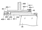
- FIG. 3 is a diagram showing a different form of the tilt adjustment mechanism.
- the inner lens frame 40-1 has a screw portion 40B-1 formed at the tip (left side in FIG. 3), and a rib 40C-1 is formed adjacent to the screw portion 40B-1.
- a rib 42b-1 is formed at the tip of the main body 42A-1 of the outer lens frame 42-1.
- a screw hole 42a-1 is formed in the vicinity of the rear end (right side in FIG. 3) of the main body 42A-1 so as to penetrate the main body 42A-1 in the radial direction. 48 is screwed together.
- the outer lens frame 42-1 is disposed in the main body ring 10, the inner lens frame 40-1 is inserted into the outer lens frame 42-1 from the rear end side, and the presser ring 44-1 is inserted from the front end side.
- the tilt adjustment mechanism is assembled by screwing with the screw portion 40B-1.
- the inner lens frame 40-1 rotates clockwise with the convex portion 40D serving as a fulcrum, and accordingly, the correction lens 26 rotates clockwise.
- the optical axis of the correction lens 26 is adjusted to be obliquely upward with respect to the optical axis P.
- the screwing amount of the screw 48 is decreased, the screw 48 is retracted radially outward (upper side in FIG. 3), and the inner lens frame 40-1 is moved back. Thereby, the inclination of the optical axis of the correction lens 26 is reduced, and the correction lens 26 can be rotated by a minute angle.
- the convex portion 40D is formed on the inner lens frame 40 and the inner lens frame 40 and the outer lens frame 42 are brought into contact with each other.
- the convex portion is formed on the outer lens frame 42 and the inner lens frame 40 is formed. 40 and the outer lens frame 42 may be brought into contact with each other.
- the rib 42b is formed at the position where the tilt adjustment mechanism is disposed, but the rib 42b may be disposed at least at two positions (up and down (or left and right)).
- an O-ring is used as the elastic member.
- the elastic member serves as a buffer when the inner lens frame 40 is rotated, and is disposed so as to be pressed from both the inner lens frame 40 and the outer lens frame 42. It is not limited to this if possible.
- the recess 40E may be eliminated, and a plate-like member having elasticity such as rubber packing may be attached.
- four tilt adjustment mechanisms are arranged at approximately every 90 degrees so as to have a vertical / left / right positional relationship, but the number and arrangement of the tilt adjustment mechanisms are not limited thereto.
- the number of the fall adjustment mechanisms may be two or three as long as it is four or less. In the case of two, it is desirable to arrange them in a positional relationship of approximately 90 degrees (for example, top and side). In the case of three, it is desirable to arrange them at intervals of approximately 120 degrees. Also, the number of four is not limited to the case where they are arranged vertically and horizontally. However, it is most desirable to provide a tilt adjustment mechanism at four locations, top, bottom, left, and right so that the tilt can be adjusted separately for the top, bottom, left and right. Even if more than four tilt adjustment mechanisms are provided, the precision and ease of tilt adjustment are not improved, and there is no point in arranging more than four.
- the tilt adjustment mechanism is applied to the correction lens 26 that is a moving lens.
- the tilt adjustment mechanism is not limited to the correction lens 26.
- the present invention may be applied to a moving lens other than the correction lens 26, or may be applied to a fixed lens that does not move in the optical axis direction.
- a screw instead of providing an opening in a cylinder such as a main body ring, a screw may be projected from the cylinder using a long screw.
Abstract
La présente invention concerne un dispositif de lentille dans lequel un gabarit de réglage (2) est inséré dans une ouverture (10A) et une ouverture (12A) pour faire tourner une vis positionnée sur un cadre de lentille intérieur (40) qui soutient une lentille correctrice (26). Le bout du cadre de lentille intérieur (40) est déplacé vers l'axe optique ou radialement vers l'extérieur de la lentille correctrice (26) pendant la rotation de ladite vis. Ainsi, le cadre de lentille intérieur (40) est respectivement déplacé vers l'axe optique ou radialement vers l'extérieur de la lentille correctrice (26), et l'inclinaison de la lentille correctrice (26) en est réduit.
Priority Applications (3)
| Application Number | Priority Date | Filing Date | Title |
|---|---|---|---|
| JP2013505943A JP5480445B2 (ja) | 2011-03-24 | 2012-03-16 | レンズ装置 |
| CN201280014954.7A CN103460100B (zh) | 2011-03-24 | 2012-03-16 | 镜头装置 |
| US14/031,688 US8743472B2 (en) | 2011-03-24 | 2013-09-19 | Lens device |
Applications Claiming Priority (2)
| Application Number | Priority Date | Filing Date | Title |
|---|---|---|---|
| JP2011-066445 | 2011-03-24 | ||
| JP2011066445 | 2011-03-24 |
Related Child Applications (1)
| Application Number | Title | Priority Date | Filing Date |
|---|---|---|---|
| US14/031,688 Continuation US8743472B2 (en) | 2011-03-24 | 2013-09-19 | Lens device |
Publications (1)
| Publication Number | Publication Date |
|---|---|
| WO2012128203A1 true WO2012128203A1 (fr) | 2012-09-27 |
Family
ID=46879350
Family Applications (1)
| Application Number | Title | Priority Date | Filing Date |
|---|---|---|---|
| PCT/JP2012/056834 WO2012128203A1 (fr) | 2011-03-24 | 2012-03-16 | Dispositif de lentille |
Country Status (4)
| Country | Link |
|---|---|
| US (1) | US8743472B2 (fr) |
| JP (1) | JP5480445B2 (fr) |
| CN (1) | CN103460100B (fr) |
| WO (1) | WO2012128203A1 (fr) |
Cited By (1)
| Publication number | Priority date | Publication date | Assignee | Title |
|---|---|---|---|---|
| WO2022201877A1 (fr) * | 2021-03-23 | 2022-09-29 | 株式会社nittoh | Barillet de lentille |
Families Citing this family (3)
| Publication number | Priority date | Publication date | Assignee | Title |
|---|---|---|---|---|
| CN107229100A (zh) | 2011-07-20 | 2017-10-03 | 株式会社尼康 | 透镜镜筒以及拍摄装置 |
| JP7218196B2 (ja) * | 2019-02-06 | 2023-02-06 | キヤノン株式会社 | レンズ装置およびこれを備える撮像装置 |
| CN114442251B (zh) * | 2021-12-15 | 2023-11-10 | 北京空间机电研究所 | 一种透镜装配组件及中大口径透镜装配方法 |
Citations (4)
| Publication number | Priority date | Publication date | Assignee | Title |
|---|---|---|---|---|
| JP2000066076A (ja) * | 1998-08-21 | 2000-03-03 | Fuji Photo Optical Co Ltd | レンズ鏡筒 |
| JP2000193868A (ja) * | 1998-12-25 | 2000-07-14 | Olympus Optical Co Ltd | 光軸調整機構 |
| JP2002283082A (ja) * | 2001-03-26 | 2002-10-02 | Sumitomo Heavy Ind Ltd | レーザ出射装置 |
| JP2005070417A (ja) * | 2003-08-25 | 2005-03-17 | Pentax Corp | レンズ調整装置 |
Family Cites Families (4)
| Publication number | Priority date | Publication date | Assignee | Title |
|---|---|---|---|---|
| US6204979B1 (en) | 1998-08-21 | 2001-03-20 | Fuji Photo Optical Co., Ltd. | Lens assembly and eccentricity adjustment apparatus thereof |
| JP2002196204A (ja) * | 2000-12-26 | 2002-07-12 | Canon Inc | 光学機器 |
| JP2004184744A (ja) | 2002-12-04 | 2004-07-02 | Pentax Corp | レンズ鏡筒のティルト調整機構 |
| JP4403516B2 (ja) * | 2007-01-12 | 2010-01-27 | ソニー株式会社 | 検出素子の取付構造及び撮像装置 |
-
2012
- 2012-03-16 WO PCT/JP2012/056834 patent/WO2012128203A1/fr active Application Filing
- 2012-03-16 CN CN201280014954.7A patent/CN103460100B/zh not_active Expired - Fee Related
- 2012-03-16 JP JP2013505943A patent/JP5480445B2/ja not_active Expired - Fee Related
-
2013
- 2013-09-19 US US14/031,688 patent/US8743472B2/en not_active Expired - Fee Related
Patent Citations (4)
| Publication number | Priority date | Publication date | Assignee | Title |
|---|---|---|---|---|
| JP2000066076A (ja) * | 1998-08-21 | 2000-03-03 | Fuji Photo Optical Co Ltd | レンズ鏡筒 |
| JP2000193868A (ja) * | 1998-12-25 | 2000-07-14 | Olympus Optical Co Ltd | 光軸調整機構 |
| JP2002283082A (ja) * | 2001-03-26 | 2002-10-02 | Sumitomo Heavy Ind Ltd | レーザ出射装置 |
| JP2005070417A (ja) * | 2003-08-25 | 2005-03-17 | Pentax Corp | レンズ調整装置 |
Cited By (1)
| Publication number | Priority date | Publication date | Assignee | Title |
|---|---|---|---|---|
| WO2022201877A1 (fr) * | 2021-03-23 | 2022-09-29 | 株式会社nittoh | Barillet de lentille |
Also Published As
| Publication number | Publication date |
|---|---|
| CN103460100A (zh) | 2013-12-18 |
| CN103460100B (zh) | 2014-12-24 |
| JP5480445B2 (ja) | 2014-04-23 |
| US20140022652A1 (en) | 2014-01-23 |
| US8743472B2 (en) | 2014-06-03 |
| JPWO2012128203A1 (ja) | 2014-07-24 |
Similar Documents
| Publication | Publication Date | Title |
|---|---|---|
| JP5480445B2 (ja) | レンズ装置 | |
| JP5600440B2 (ja) | 監視カメラ用レンズ装置 | |
| US11320627B2 (en) | Lens barrel and imaging device | |
| JP2008046439A (ja) | チルト調整機構を備えたレンズ鏡筒 | |
| JP2000066076A (ja) | レンズ鏡筒 | |
| US10254506B2 (en) | Lens apparatus and image pickup apparatus | |
| US7782557B2 (en) | Lens position adjusting device | |
| JP4910138B2 (ja) | フォーカス調整機構を備えたレンズ鏡筒 | |
| US20180321461A1 (en) | Lens barrel and imaging apparatus | |
| JP2011022461A (ja) | 光学装置及び光学機器 | |
| JP2007133089A (ja) | レンズ鏡筒 | |
| JP2006301187A (ja) | ズームレンズ沈胴鏡筒 | |
| US10495841B2 (en) | Lens barrel and imaging device | |
| JP2004184744A (ja) | レンズ鏡筒のティルト調整機構 | |
| JP5479650B2 (ja) | レンズ装置 | |
| KR20100020216A (ko) | 광학계 경통 | |
| JP2013125229A (ja) | レンズ鏡筒および撮像装置 | |
| JP2021117235A (ja) | レンズ装置および撮像装置 | |
| JP2009042668A (ja) | レンズ鏡筒 | |
| JP6669025B2 (ja) | レンズ鏡筒 | |
| JP2007003581A (ja) | レンズ鏡筒 | |
| JP2013122485A (ja) | レンズ鏡筒およびレンズユニット | |
| JP2009020429A (ja) | 光学ユニット、それを備えたレンズ鏡筒および光学ユニットの製造方法 | |
| JP6991790B2 (ja) | レンズ鏡筒および撮像装置 | |
| JP5538136B2 (ja) | 偏心調整機構を備えたレンズ鏡筒 |
Legal Events
| Date | Code | Title | Description |
|---|---|---|---|
| 121 | Ep: the epo has been informed by wipo that ep was designated in this application |
Ref document number: 12760392 Country of ref document: EP Kind code of ref document: A1 |
|
| ENP | Entry into the national phase |
Ref document number: 2013505943 Country of ref document: JP Kind code of ref document: A |
|
| NENP | Non-entry into the national phase |
Ref country code: DE |
|
| 122 | Ep: pct application non-entry in european phase |
Ref document number: 12760392 Country of ref document: EP Kind code of ref document: A1 |