WO2012127876A1 - 電気接続箱 - Google Patents
電気接続箱 Download PDFInfo
- Publication number
- WO2012127876A1 WO2012127876A1 PCT/JP2012/002035 JP2012002035W WO2012127876A1 WO 2012127876 A1 WO2012127876 A1 WO 2012127876A1 JP 2012002035 W JP2012002035 W JP 2012002035W WO 2012127876 A1 WO2012127876 A1 WO 2012127876A1
- Authority
- WO
- WIPO (PCT)
- Prior art keywords
- bus bar
- terminal
- junction box
- case
- electrical junction
- Prior art date
- Legal status (The legal status is an assumption and is not a legal conclusion. Google has not performed a legal analysis and makes no representation as to the accuracy of the status listed.)
- Ceased
Links
Images




Classifications
-
- H—ELECTRICITY
- H02—GENERATION; CONVERSION OR DISTRIBUTION OF ELECTRIC POWER
- H02G—INSTALLATION OF ELECTRIC CABLES OR LINES, OR OF COMBINED OPTICAL AND ELECTRIC CABLES OR LINES
- H02G3/00—Installations of electric cables or lines or protective tubing therefor in or on buildings, equivalent structures or vehicles
- H02G3/02—Details
- H02G3/08—Distribution boxes; Connection or junction boxes
-
- B—PERFORMING OPERATIONS; TRANSPORTING
- B60—VEHICLES IN GENERAL
- B60R—VEHICLES, VEHICLE FITTINGS, OR VEHICLE PARTS, NOT OTHERWISE PROVIDED FOR
- B60R16/00—Electric or fluid circuits specially adapted for vehicles and not otherwise provided for; Arrangement of elements of electric or fluid circuits specially adapted for vehicles and not otherwise provided for
- B60R16/02—Electric or fluid circuits specially adapted for vehicles and not otherwise provided for; Arrangement of elements of electric or fluid circuits specially adapted for vehicles and not otherwise provided for electric constitutive elements
- B60R16/023—Electric or fluid circuits specially adapted for vehicles and not otherwise provided for; Arrangement of elements of electric or fluid circuits specially adapted for vehicles and not otherwise provided for electric constitutive elements for transmission of signals between vehicle parts or subsystems
- B60R16/0238—Electrical distribution centers
-
- B—PERFORMING OPERATIONS; TRANSPORTING
- B60—VEHICLES IN GENERAL
- B60R—VEHICLES, VEHICLE FITTINGS, OR VEHICLE PARTS, NOT OTHERWISE PROVIDED FOR
- B60R16/00—Electric or fluid circuits specially adapted for vehicles and not otherwise provided for; Arrangement of elements of electric or fluid circuits specially adapted for vehicles and not otherwise provided for
- B60R16/02—Electric or fluid circuits specially adapted for vehicles and not otherwise provided for; Arrangement of elements of electric or fluid circuits specially adapted for vehicles and not otherwise provided for electric constitutive elements
- B60R16/023—Electric or fluid circuits specially adapted for vehicles and not otherwise provided for; Arrangement of elements of electric or fluid circuits specially adapted for vehicles and not otherwise provided for electric constitutive elements for transmission of signals between vehicle parts or subsystems
- B60R16/0239—Electronic boxes
-
- H—ELECTRICITY
- H02—GENERATION; CONVERSION OR DISTRIBUTION OF ELECTRIC POWER
- H02G—INSTALLATION OF ELECTRIC CABLES OR LINES, OR OF COMBINED OPTICAL AND ELECTRIC CABLES OR LINES
- H02G3/00—Installations of electric cables or lines or protective tubing therefor in or on buildings, equivalent structures or vehicles
- H02G3/02—Details
- H02G3/08—Distribution boxes; Connection or junction boxes
- H02G3/086—Assembled boxes
-
- H—ELECTRICITY
- H02—GENERATION; CONVERSION OR DISTRIBUTION OF ELECTRIC POWER
- H02G—INSTALLATION OF ELECTRIC CABLES OR LINES, OR OF COMBINED OPTICAL AND ELECTRIC CABLES OR LINES
- H02G3/00—Installations of electric cables or lines or protective tubing therefor in or on buildings, equivalent structures or vehicles
- H02G3/02—Details
- H02G3/08—Distribution boxes; Connection or junction boxes
- H02G3/18—Distribution boxes; Connection or junction boxes providing line outlets
Definitions
- the present invention relates to a configuration for protecting a bus bar in an electrical junction box.
- an electrical junction box that accommodates many electrical components such as fuses and relays. And each electric component is connected to the electronic device arrange
- Such an electrical junction box is disclosed in Patent Document 1 and Patent Document 2, for example.
- the electrical junction box disclosed in Patent Literature 1 and Patent Literature 2 includes a component mounting block (relay block, cassette block) to which an electrical component is attached, and a case that accommodates the component mounting block. Yes.
- Patent Literature 3 and Patent Literature 4 disclose an electrical junction box including a bus bar.
- Patent Document 3 discloses a configuration in which a bus bar is inserted and screwed into an insulating block from above the insulating block.
- Patent Document 4 points out that in the configuration of Patent Document 3, it is necessary to form a slit for accommodating the bus bar in the cavity, which causes problems such as a decrease in strength and a decrease in accuracy.
- Patent Document 4 discloses a configuration in which a bus bar is inserted from below the insulating block in order to solve this problem. According to Patent Document 4, a slit for inserting a bus bar is not required in the cavity above the insulating block.
- Patent Document 3 In order to cover and protect the entire bus bar with the configuration of Patent Document 3, it is necessary to form a slit for housing the bus bar deeper than the height of the bus bar. However, when the slits are formed deeply in this way, there is a problem that the insulating block is enlarged.
- Patent Document 4 has a configuration in which the slit is omitted, but the configuration is such that the bus bar is accommodated in the insulating block, so the insulating block is enlarged to cover and protect the entire bus bar. I have to.
- the present invention has been made in view of the above circumstances, and a main object of the present invention is to provide an electric connection box that can be downsized while appropriately protecting a bus bar.
- the electrical connection box includes a terminal accommodating portion that accommodates a connection terminal, and a case that accommodates the terminal accommodating portion.
- a bus bar is inserted into the terminal accommodating portion, and an end portion of the bus bar protrudes from the terminal accommodating portion.
- the case is formed with a protective portion that covers the end portion of the bus bar protruding from the terminal accommodating portion. And by accommodating the said terminal accommodating part in the said case, the edge part of the said bus-bar is covered with the said protection part.
- the terminal accommodating portion can be configured more compactly than the conventional configuration in which the entire bus bar is covered by the terminal accommodating portion.
- the end portion of the bus bar protruding from the terminal accommodating portion can be protected by being covered with a protective portion formed on the case side.
- the edge part of a bus bar can be covered only by accommodating a terminal accommodating part in a case, the special operation
- the protection part is configured as a groove part having a substantially U-shaped cross section, and the bus bar is accommodated inside the groove part.
- the width of the opening of the protection part formed in the groove shape is wider than the thickness of the bus bar.
- the terminal accommodating portion is configured as a separate member from the case.
- the molds are provided separately for the terminal accommodating part and the case, the mold of the terminal accommodating part, which tends to have a complicated structure, can be miniaturized. This facilitates maintenance of the mold.
- the terminal housing portion is made of a heat-resistant material or a heat insulating material, and the case is made of an inexpensive material, so that the terminal housing portion and the case material can be made different.
- the electrical connection box 10 includes a terminal housing block (terminal housing portion) 11 and a case 12 that houses the terminal housing block 11.
- the terminal housing block 11 and the case 12 are formed of synthetic resin.
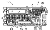
- FIG. 1 is a view of the electrical junction box 10 as viewed from the component mounting surface 13 side.
- a plurality of connectors 14 on which electrical components (not shown) such as fuses and relays are mounted are formed on the component mounting surface 13.
- the electrical component is mounted on the connector 14, the electrical component is electrically connected to a connection terminal (not shown) included in the connector.
- Each connector 14 has a terminal accommodating chamber 15 in which the connection terminal is accommodated.
- a lance (not shown) for locking the connection terminal is formed in the terminal accommodating chamber 15.
- the terminal accommodating chamber 15 is formed so as to penetrate the terminal accommodating block 11 and communicates with the side opposite to the component mounting surface 13.
- a surface opposite to the component mounting surface 13 is a terminal insertion surface 16.
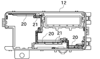
- FIG. 2 is a view of the electrical junction box 10 as viewed from the terminal insertion surface 16 side. The connection terminal is inserted into the terminal accommodating chamber 15 from the terminal insertion surface 16 side.
- the terminal receiving block 11 is formed with a block side engaging portion 17 that engages with the case 12.
- a case side engaging portion 18 that engages with the block side engaging portion 17 is formed at a position corresponding to the block side engaging portion 17. And when the terminal accommodating block 11 is accommodated in the case 12, the block side engaging part 17 and the case side engaging part 18 are engaged, whereby both are fixed.
- the bus bar 19 is inserted into the specific terminal accommodating chamber 15 from the terminal insertion surface 16 side.
- the bus bar 19 is configured by appropriately bending a metal plate, and is connected to an electrical component mounted on the connector 14 to supply power, for example.
- the bus bar 19 is formed with a locking hole (not shown), and a cantilever lance (not shown) of the terminal receiving block 11 is engaged with the locking hole, so that the bus bar 19 is connected to the terminal receiving block. 11 is fixed.
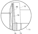
- the bus bar 19 protrudes from the terminal insertion surface 16 of the terminal accommodating block 11 as shown in FIGS. 3 and 4 when inserted in the terminal accommodating chamber 15.
- the terminal accommodating block 11 is comprised so that the edge part of the insertion direction opposite side of the bus-bar 19 may not be covered.
- the conventional electrical junction box has a configuration in which the bus bar is covered and protected by the terminal housing block, so that there is a problem that the terminal housing block is enlarged.
- the terminal housing block 11 can be reduced in size, and thereby the entire electrical junction box 10 can be configured compactly.
- the case 12 is provided with a protection unit 20 for protecting the bus bar 19.
- the bus bar 19 protruding from the terminal accommodating block 11 can be covered and protected.
- the protection unit 20 is in the longitudinal direction of the bus bar 19 (the direction perpendicular to the thickness direction of the bus bar 19 and the insertion direction of the bus bar 19 with respect to the terminal housing block 11). It is formed as a rib-like portion formed along the side.
- the rib-shaped protection part 20 is hollow and has a shape with one side open.
- the protective portion 20 is a groove portion whose cross-sectional shape when cut along a plane perpendicular to the longitudinal direction of the bus bar 19 is substantially U-shaped (substantially U-shaped). It is configured as.
- the width of the opening of the protection part 20 is slightly wider than the thickness of the bus bar 19 so that the bus bar 19 can be easily inserted. Furthermore, as shown in FIG. 6, the inner wall surface of the protection part 20 is formed so as to spread toward the opening. Thereby, it becomes easier to insert the bus bar 19 into the protection part 20. A rib portion 21 for guiding the bus bar 19 is formed on a part of the inner wall surface of the protection portion 20.
- the electrical junction box 10 configured as described above is assembled as follows.
- connection terminals and the bus bar 19 are inserted into the terminal accommodating chamber 15 from the terminal insertion surface 16 side. At this time, the connection terminal and the bus bar 19 are locked by the lance and fixed so as not to come out of the terminal accommodating chamber 15. As described above, the end of the bus bar 19 inserted into the terminal accommodating chamber 15 protrudes from the terminal insertion surface 16 of the terminal accommodating block 11.
- the case 12 is attached to the terminal receiving block 11 from the terminal insertion surface 16 side.
- the protection part 20 is formed so that the opening of the protection part 20 faces the terminal housing block 11 side.
- the protection unit 20 is formed along the longitudinal direction of the bus bar 19.
- the protection unit 20 is formed at a position corresponding to the position of the bus bar 19 inserted into the terminal housing block 11.
- the bus bar 19 is inserted inside the protection unit 20 without requiring any special operation.
- the width of the opening of the protection part 20 is formed wider than the thickness of the bus bar 19, and the protection part 20 is formed so as to expand toward the opening.
- the bus bar 19 can be smoothly inserted into the protection part 20 without requiring alignment.
- the end of the bus bar 19 protruding from the terminal accommodating block 11 can be covered and protected simply by attaching the case 12 to the terminal accommodating block 11. Then, the terminal housing block 11 and the case 12 are fixed by fitting the block side engaging portion 17 and the case side engaging portion 18 together.
- the electrical junction box 10 of the present embodiment includes the terminal housing block 11 that houses the connection terminals, and the case 12 that houses the terminal housing block 11.
- a bus bar 19 is inserted into the terminal receiving block 11, and an end of the bus bar 19 opposite to the insertion direction protrudes from the terminal receiving block 11.
- the case 12 is formed with a protective portion 20 that covers the end portion of the bus bar 19 protruding from the terminal housing block 11. Then, by housing the terminal housing block 11 in the case 12, the end portion of the bus bar 19 is covered by the protection unit 20.
- the terminal accommodating block 11 can be configured more compactly than the conventional configuration in which the entire bus bar is covered by the terminal accommodating block.
- the end portion of the bus bar 19 protruding from the terminal housing block 11 can be protected by being covered with a protection portion 20 formed on the case 12 side.
- the edge part of the bus bar 19 can be covered only by accommodating the terminal accommodation block 11 in the case 12, the special operation
- the protection part 20 is configured as a groove part having a substantially U-shaped cross section, and the bus bar 19 is accommodated inside the groove part.
- the tip of the bus bar 19 can be completely covered.
- the width of the opening of the protective portion 20 formed in the groove shape is wider than the thickness of the bus bar 19.
- the bus bar 19 can be smoothly inserted into the protection unit 20.
- the terminal accommodation block 11 and the case 12 are divided and a metal mold
- the shape of the terminal accommodating portion, the case, the bus bar, etc. is not limited to that shown in the figure, but can be changed as appropriate.
- the shape of the protection portion has been described as a groove portion having a U-shaped cross section, but the shape is not limited as long as the shape can cover and protect the bus bar.
- the bus bar 19 is inserted from the terminal insertion surface 16 side.
- the bus bar 19 is inserted from the component mounting surface 13 side, and the terminal housing block 11 is penetrated to protrude to the terminal insertion surface 16 side. It may be.
- Terminal housing block terminal housing part
- Case Bus bar 20 Protection part
Landscapes
- Engineering & Computer Science (AREA)
- Mechanical Engineering (AREA)
- Architecture (AREA)
- Civil Engineering (AREA)
- Structural Engineering (AREA)
- Connection Or Junction Boxes (AREA)
Abstract
Description
11 端子収容ブロック(端子収容部)
12 ケース
19 バスバー
20 保護部
Claims (4)
- 接続端子が収容される端子収容部と、
前記端子収容部を収容するケースと、
を備え、
前記端子収容部には、バスバーが挿入されるとともに、当該バスバーの端部は前記端子収容部から突出し、
前記ケースには、前記端子収容部から突出した前記バスバーの前記端部を覆う保護部が形成されており、
前記ケースに前記端子収容部を収容することにより、前記バスバーの端部が前記保護部によって覆われることを特徴とする電気接続箱。 - 請求項1に記載の電気接続箱であって、
前記保護部は、断面形状が略U字状に形成された溝部として構成されており、前記溝部の内側に前記バスバーを収容する構成であることを特徴とする電気接続箱。 - 請求項2に記載の電気接続箱であって、
前記溝部として構成された前記保護部の開口部の幅は、前記バスバーの厚みよりも広く形成されていることを特徴とする電気接続箱。 - 請求項1から3までの何れか一項に記載の電気接続箱であって、
前記端子収容部は、前記ケースとは別部材として構成されていることを特徴とする電気接続箱。
Priority Applications (3)
| Application Number | Priority Date | Filing Date | Title |
|---|---|---|---|
| JP2013505824A JP5667287B2 (ja) | 2011-03-24 | 2012-03-23 | 電気接続箱 |
| CN201280014676.5A CN103444031B (zh) | 2011-03-24 | 2012-03-23 | 电气接线盒 |
| US14/007,301 US9148002B2 (en) | 2011-03-24 | 2012-03-23 | Electrical junction box |
Applications Claiming Priority (2)
| Application Number | Priority Date | Filing Date | Title |
|---|---|---|---|
| JP2011066613 | 2011-03-24 | ||
| JP2011-066613 | 2011-03-24 |
Publications (1)
| Publication Number | Publication Date |
|---|---|
| WO2012127876A1 true WO2012127876A1 (ja) | 2012-09-27 |
Family
ID=46879047
Family Applications (1)
| Application Number | Title | Priority Date | Filing Date |
|---|---|---|---|
| PCT/JP2012/002035 Ceased WO2012127876A1 (ja) | 2011-03-24 | 2012-03-23 | 電気接続箱 |
Country Status (4)
| Country | Link |
|---|---|
| US (1) | US9148002B2 (ja) |
| JP (1) | JP5667287B2 (ja) |
| CN (1) | CN103444031B (ja) |
| WO (1) | WO2012127876A1 (ja) |
Cited By (1)
| Publication number | Priority date | Publication date | Assignee | Title |
|---|---|---|---|---|
| JP2019068633A (ja) * | 2017-10-02 | 2019-04-25 | 矢崎総業株式会社 | 電気接続箱およびワイヤハーネス |
Families Citing this family (7)
| Publication number | Priority date | Publication date | Assignee | Title |
|---|---|---|---|---|
| JP5875154B2 (ja) * | 2012-07-25 | 2016-03-02 | 矢崎総業株式会社 | 電気接続箱 |
| US9667002B1 (en) * | 2016-10-24 | 2017-05-30 | Te Connectivity Corporation | Connector assembly with an unshielded twisted pair circuit |
| JP7083701B2 (ja) * | 2018-06-07 | 2022-06-13 | 矢崎総業株式会社 | ロック構造、電気接続箱及びワイヤハーネス |
| JP7173760B2 (ja) * | 2018-06-07 | 2022-11-16 | 矢崎総業株式会社 | ロック構造、電気接続箱及びワイヤハーネス |
| JP6984983B2 (ja) * | 2019-05-10 | 2021-12-22 | 矢崎総業株式会社 | 電気接続箱 |
| JP7120974B2 (ja) * | 2019-08-26 | 2022-08-17 | 矢崎総業株式会社 | 電気接続箱 |
| US20240308450A1 (en) * | 2023-03-17 | 2024-09-19 | Sumitomo Wiring Systems, Ltd. | Junction box assembly having a rib for reinforcing an outer wall |
Citations (2)
| Publication number | Priority date | Publication date | Assignee | Title |
|---|---|---|---|---|
| JPH09327112A (ja) * | 1996-06-07 | 1997-12-16 | Yazaki Corp | 電気接続箱 |
| JP2009165220A (ja) * | 2007-12-28 | 2009-07-23 | Furukawa Electric Co Ltd:The | 電気接続箱 |
Family Cites Families (6)
| Publication number | Priority date | Publication date | Assignee | Title |
|---|---|---|---|---|
| US5295847A (en) * | 1990-01-16 | 1994-03-22 | Yazaki Corporation | Branch junction box and busbars for branch connection |
| JP3977177B2 (ja) | 2002-07-09 | 2007-09-19 | 古河電気工業株式会社 | 電気接続箱におけるリレーブロックの取付構造 |
| EP1577977B1 (en) * | 2004-03-17 | 2007-08-29 | Sumitomo Wiring Systems, Ltd. | Electrical junction box |
| JP2006004773A (ja) | 2004-06-17 | 2006-01-05 | Mitsumi Electric Co Ltd | 電池保護回路モジュール |
| JP5030225B2 (ja) | 2007-10-01 | 2012-09-19 | 矢崎総業株式会社 | 電気接続箱 |
| JP2010081738A (ja) | 2008-09-26 | 2010-04-08 | Yazaki Corp | 機器、及び、前記機器を構成する部品とケースとの輸送方法 |
-
2012
- 2012-03-23 US US14/007,301 patent/US9148002B2/en active Active
- 2012-03-23 JP JP2013505824A patent/JP5667287B2/ja active Active
- 2012-03-23 WO PCT/JP2012/002035 patent/WO2012127876A1/ja not_active Ceased
- 2012-03-23 CN CN201280014676.5A patent/CN103444031B/zh active Active
Patent Citations (2)
| Publication number | Priority date | Publication date | Assignee | Title |
|---|---|---|---|---|
| JPH09327112A (ja) * | 1996-06-07 | 1997-12-16 | Yazaki Corp | 電気接続箱 |
| JP2009165220A (ja) * | 2007-12-28 | 2009-07-23 | Furukawa Electric Co Ltd:The | 電気接続箱 |
Cited By (1)
| Publication number | Priority date | Publication date | Assignee | Title |
|---|---|---|---|---|
| JP2019068633A (ja) * | 2017-10-02 | 2019-04-25 | 矢崎総業株式会社 | 電気接続箱およびワイヤハーネス |
Also Published As
| Publication number | Publication date |
|---|---|
| JP5667287B2 (ja) | 2015-02-12 |
| JPWO2012127876A1 (ja) | 2014-07-24 |
| CN103444031A (zh) | 2013-12-11 |
| US9148002B2 (en) | 2015-09-29 |
| US20140083732A1 (en) | 2014-03-27 |
| CN103444031B (zh) | 2017-05-17 |
Similar Documents
| Publication | Publication Date | Title |
|---|---|---|
| JP5667287B2 (ja) | 電気接続箱 | |
| JP6441112B2 (ja) | 電子部品ユニット、及び、ワイヤハーネス | |
| JP6265865B2 (ja) | 電子部品 | |
| EP2889890B1 (en) | Electronic component assembly, connection structure of electronic component assembly and terminal fitting, and electrical connection box having electronic component assembly | |
| EP2405729B1 (en) | Connector cover and junction box unit provided with the same | |
| EP2715765B1 (en) | Fusible link mounting structure and electrical junction box | |
| JP5382526B2 (ja) | 電気接続箱 | |
| JP2018093671A (ja) | 電気接続箱、及び、ワイヤハーネス | |
| JP5047824B2 (ja) | 電気接続箱 | |
| JP6227371B2 (ja) | 救援端子ブロック、救援端子ブロックとフレームのアセンブリ | |
| JP6575767B2 (ja) | 暗電流回路用ヒューズの断続構造 | |
| JP4974173B2 (ja) | 電気接続箱 | |
| CN103812064B (zh) | 电气接线盒 | |
| JP2020080587A (ja) | バスバー組み付け構造、電気接続箱、及びワイヤハーネス | |
| JP4319901B2 (ja) | 電気接続箱 | |
| JP5888801B1 (ja) | 電気接続箱 | |
| JP5024946B2 (ja) | 電気接続箱 | |
| JP4677286B2 (ja) | 電気接続箱 | |
| JP5264373B2 (ja) | ヒューズブロック | |
| JP4198044B2 (ja) | 電気接続箱のバスバー組付構造 | |
| JP2018097947A (ja) | ヒューズユニット | |
| JP3174349U (ja) | プリント基板用端子台 | |
| JP2007189864A (ja) | 電気接続箱 | |
| JP6887929B2 (ja) | 電気接続箱およびワイヤハーネス | |
| JP2007312494A (ja) | 電気接続箱 |
Legal Events
| Date | Code | Title | Description |
|---|---|---|---|
| 121 | Ep: the epo has been informed by wipo that ep was designated in this application |
Ref document number: 12760683 Country of ref document: EP Kind code of ref document: A1 |
|
| ENP | Entry into the national phase |
Ref document number: 2013505824 Country of ref document: JP Kind code of ref document: A |
|
| NENP | Non-entry into the national phase |
Ref country code: DE |
|
| WWE | Wipo information: entry into national phase |
Ref document number: 14007301 Country of ref document: US |
|
| 122 | Ep: pct application non-entry in european phase |
Ref document number: 12760683 Country of ref document: EP Kind code of ref document: A1 |