WO2012127677A1 - 車両および車両用制御方法 - Google Patents
車両および車両用制御方法 Download PDFInfo
- Publication number
- WO2012127677A1 WO2012127677A1 PCT/JP2011/057151 JP2011057151W WO2012127677A1 WO 2012127677 A1 WO2012127677 A1 WO 2012127677A1 JP 2011057151 W JP2011057151 W JP 2011057151W WO 2012127677 A1 WO2012127677 A1 WO 2012127677A1
- Authority
- WO
- WIPO (PCT)
- Prior art keywords
- vehicle
- occupant
- engine
- mode
- instruction
- Prior art date
Links
- 238000000034 method Methods 0.000 title claims description 24
- 230000004397 blinking Effects 0.000 claims abstract description 18
- 238000002485 combustion reaction Methods 0.000 claims description 18
- 230000004913 activation Effects 0.000 claims description 17
- 238000002360 preparation method Methods 0.000 claims description 5
- 230000005540 biological transmission Effects 0.000 claims description 4
- 238000006243 chemical reaction Methods 0.000 claims description 4
- 230000004044 response Effects 0.000 claims description 3
- 239000007787 solid Substances 0.000 abstract 2
- 230000007704 transition Effects 0.000 abstract 1
- 239000000446 fuel Substances 0.000 description 13
- 230000008569 process Effects 0.000 description 12
- 230000006870 function Effects 0.000 description 7
- 238000010586 diagram Methods 0.000 description 5
- 238000002347 injection Methods 0.000 description 5
- 239000007924 injection Substances 0.000 description 5
- 239000003638 chemical reducing agent Substances 0.000 description 4
- 230000007423 decrease Effects 0.000 description 4
- 230000008859 change Effects 0.000 description 3
- 238000004880 explosion Methods 0.000 description 3
- 230000001172 regenerating effect Effects 0.000 description 3
- 230000003247 decreasing effect Effects 0.000 description 2
- 230000007246 mechanism Effects 0.000 description 2
- 230000009467 reduction Effects 0.000 description 2
- HBBGRARXTFLTSG-UHFFFAOYSA-N Lithium ion Chemical compound [Li+] HBBGRARXTFLTSG-UHFFFAOYSA-N 0.000 description 1
- 230000005856 abnormality Effects 0.000 description 1
- 239000003990 capacitor Substances 0.000 description 1
- 239000000498 cooling water Substances 0.000 description 1
- 230000000994 depressogenic effect Effects 0.000 description 1
- 238000007599 discharging Methods 0.000 description 1
- 230000007613 environmental effect Effects 0.000 description 1
- 230000020169 heat generation Effects 0.000 description 1
- 239000004973 liquid crystal related substance Substances 0.000 description 1
- 229910001416 lithium ion Inorganic materials 0.000 description 1
- 229910052987 metal hydride Inorganic materials 0.000 description 1
- 230000004048 modification Effects 0.000 description 1
- 238000012986 modification Methods 0.000 description 1
- 229910052759 nickel Inorganic materials 0.000 description 1
- PXHVJJICTQNCMI-UHFFFAOYSA-N nickel Substances [Ni] PXHVJJICTQNCMI-UHFFFAOYSA-N 0.000 description 1
- -1 nickel metal hydride Chemical class 0.000 description 1
- 238000010248 power generation Methods 0.000 description 1
- 230000000630 rising effect Effects 0.000 description 1
- 239000007858 starting material Substances 0.000 description 1
Images


Classifications
-
- B—PERFORMING OPERATIONS; TRANSPORTING
- B60—VEHICLES IN GENERAL
- B60K—ARRANGEMENT OR MOUNTING OF PROPULSION UNITS OR OF TRANSMISSIONS IN VEHICLES; ARRANGEMENT OR MOUNTING OF PLURAL DIVERSE PRIME-MOVERS IN VEHICLES; AUXILIARY DRIVES FOR VEHICLES; INSTRUMENTATION OR DASHBOARDS FOR VEHICLES; ARRANGEMENTS IN CONNECTION WITH COOLING, AIR INTAKE, GAS EXHAUST OR FUEL SUPPLY OF PROPULSION UNITS IN VEHICLES
- B60K6/00—Arrangement or mounting of plural diverse prime-movers for mutual or common propulsion, e.g. hybrid propulsion systems comprising electric motors and internal combustion engines ; Control systems therefor, i.e. systems controlling two or more prime movers, or controlling one of these prime movers and any of the transmission, drive or drive units Informative references: mechanical gearings with secondary electric drive F16H3/72; arrangements for handling mechanical energy structurally associated with the dynamo-electric machine H02K7/00; machines comprising structurally interrelated motor and generator parts H02K51/00; dynamo-electric machines not otherwise provided for in H02K see H02K99/00
- B60K6/20—Arrangement or mounting of plural diverse prime-movers for mutual or common propulsion, e.g. hybrid propulsion systems comprising electric motors and internal combustion engines ; Control systems therefor, i.e. systems controlling two or more prime movers, or controlling one of these prime movers and any of the transmission, drive or drive units Informative references: mechanical gearings with secondary electric drive F16H3/72; arrangements for handling mechanical energy structurally associated with the dynamo-electric machine H02K7/00; machines comprising structurally interrelated motor and generator parts H02K51/00; dynamo-electric machines not otherwise provided for in H02K see H02K99/00 the prime-movers consisting of electric motors and internal combustion engines, e.g. HEVs
- B60K6/42—Arrangement or mounting of plural diverse prime-movers for mutual or common propulsion, e.g. hybrid propulsion systems comprising electric motors and internal combustion engines ; Control systems therefor, i.e. systems controlling two or more prime movers, or controlling one of these prime movers and any of the transmission, drive or drive units Informative references: mechanical gearings with secondary electric drive F16H3/72; arrangements for handling mechanical energy structurally associated with the dynamo-electric machine H02K7/00; machines comprising structurally interrelated motor and generator parts H02K51/00; dynamo-electric machines not otherwise provided for in H02K see H02K99/00 the prime-movers consisting of electric motors and internal combustion engines, e.g. HEVs characterised by the architecture of the hybrid electric vehicle
- B60K6/44—Series-parallel type
- B60K6/445—Differential gearing distribution type
-
- B—PERFORMING OPERATIONS; TRANSPORTING
- B60—VEHICLES IN GENERAL
- B60K—ARRANGEMENT OR MOUNTING OF PROPULSION UNITS OR OF TRANSMISSIONS IN VEHICLES; ARRANGEMENT OR MOUNTING OF PLURAL DIVERSE PRIME-MOVERS IN VEHICLES; AUXILIARY DRIVES FOR VEHICLES; INSTRUMENTATION OR DASHBOARDS FOR VEHICLES; ARRANGEMENTS IN CONNECTION WITH COOLING, AIR INTAKE, GAS EXHAUST OR FUEL SUPPLY OF PROPULSION UNITS IN VEHICLES
- B60K35/00—Arrangement of adaptations of instruments
-
- B60K35/28—
-
- B—PERFORMING OPERATIONS; TRANSPORTING
- B60—VEHICLES IN GENERAL
- B60L—PROPULSION OF ELECTRICALLY-PROPELLED VEHICLES; SUPPLYING ELECTRIC POWER FOR AUXILIARY EQUIPMENT OF ELECTRICALLY-PROPELLED VEHICLES; ELECTRODYNAMIC BRAKE SYSTEMS FOR VEHICLES IN GENERAL; MAGNETIC SUSPENSION OR LEVITATION FOR VEHICLES; MONITORING OPERATING VARIABLES OF ELECTRICALLY-PROPELLED VEHICLES; ELECTRIC SAFETY DEVICES FOR ELECTRICALLY-PROPELLED VEHICLES
- B60L9/00—Electric propulsion with power supply external to the vehicle
-
- B—PERFORMING OPERATIONS; TRANSPORTING
- B60—VEHICLES IN GENERAL
- B60Q—ARRANGEMENT OF SIGNALLING OR LIGHTING DEVICES, THE MOUNTING OR SUPPORTING THEREOF OR CIRCUITS THEREFOR, FOR VEHICLES IN GENERAL
- B60Q1/00—Arrangement of optical signalling or lighting devices, the mounting or supporting thereof or circuits therefor
-
- B—PERFORMING OPERATIONS; TRANSPORTING
- B60—VEHICLES IN GENERAL
- B60W—CONJOINT CONTROL OF VEHICLE SUB-UNITS OF DIFFERENT TYPE OR DIFFERENT FUNCTION; CONTROL SYSTEMS SPECIALLY ADAPTED FOR HYBRID VEHICLES; ROAD VEHICLE DRIVE CONTROL SYSTEMS FOR PURPOSES NOT RELATED TO THE CONTROL OF A PARTICULAR SUB-UNIT
- B60W50/00—Details of control systems for road vehicle drive control not related to the control of a particular sub-unit, e.g. process diagnostic or vehicle driver interfaces
- B60W50/08—Interaction between the driver and the control system
- B60W50/14—Means for informing the driver, warning the driver or prompting a driver intervention
-
- F—MECHANICAL ENGINEERING; LIGHTING; HEATING; WEAPONS; BLASTING
- F01—MACHINES OR ENGINES IN GENERAL; ENGINE PLANTS IN GENERAL; STEAM ENGINES
- F01L—CYCLICALLY OPERATING VALVES FOR MACHINES OR ENGINES
- F01L1/00—Valve-gear or valve arrangements, e.g. lift-valve gear
- F01L1/34—Valve-gear or valve arrangements, e.g. lift-valve gear characterised by the provision of means for changing the timing of the valves without changing the duration of opening and without affecting the magnitude of the valve lift
-
- F—MECHANICAL ENGINEERING; LIGHTING; HEATING; WEAPONS; BLASTING
- F02—COMBUSTION ENGINES; HOT-GAS OR COMBUSTION-PRODUCT ENGINE PLANTS
- F02D—CONTROLLING COMBUSTION ENGINES
- F02D13/00—Controlling the engine output power by varying inlet or exhaust valve operating characteristics, e.g. timing
- F02D13/02—Controlling the engine output power by varying inlet or exhaust valve operating characteristics, e.g. timing during engine operation
-
- F—MECHANICAL ENGINEERING; LIGHTING; HEATING; WEAPONS; BLASTING
- F02—COMBUSTION ENGINES; HOT-GAS OR COMBUSTION-PRODUCT ENGINE PLANTS
- F02N—STARTING OF COMBUSTION ENGINES; STARTING AIDS FOR SUCH ENGINES, NOT OTHERWISE PROVIDED FOR
- F02N11/00—Starting of engines by means of electric motors
- F02N11/08—Circuits or control means specially adapted for starting of engines
- F02N11/0803—Circuits or control means specially adapted for starting of engines characterised by means for initiating engine start or stop
-
- B60K2360/16—
-
- B—PERFORMING OPERATIONS; TRANSPORTING
- B60—VEHICLES IN GENERAL
- B60W—CONJOINT CONTROL OF VEHICLE SUB-UNITS OF DIFFERENT TYPE OR DIFFERENT FUNCTION; CONTROL SYSTEMS SPECIALLY ADAPTED FOR HYBRID VEHICLES; ROAD VEHICLE DRIVE CONTROL SYSTEMS FOR PURPOSES NOT RELATED TO THE CONTROL OF A PARTICULAR SUB-UNIT
- B60W50/00—Details of control systems for road vehicle drive control not related to the control of a particular sub-unit, e.g. process diagnostic or vehicle driver interfaces
- B60W50/08—Interaction between the driver and the control system
- B60W50/14—Means for informing the driver, warning the driver or prompting a driver intervention
- B60W2050/146—Display means
-
- G—PHYSICS
- G16—INFORMATION AND COMMUNICATION TECHNOLOGY [ICT] SPECIALLY ADAPTED FOR SPECIFIC APPLICATION FIELDS
- G16Z—INFORMATION AND COMMUNICATION TECHNOLOGY [ICT] SPECIALLY ADAPTED FOR SPECIFIC APPLICATION FIELDS, NOT OTHERWISE PROVIDED FOR
- G16Z99/00—Subject matter not provided for in other main groups of this subclass
-
- Y—GENERAL TAGGING OF NEW TECHNOLOGICAL DEVELOPMENTS; GENERAL TAGGING OF CROSS-SECTIONAL TECHNOLOGIES SPANNING OVER SEVERAL SECTIONS OF THE IPC; TECHNICAL SUBJECTS COVERED BY FORMER USPC CROSS-REFERENCE ART COLLECTIONS [XRACs] AND DIGESTS
- Y02—TECHNOLOGIES OR APPLICATIONS FOR MITIGATION OR ADAPTATION AGAINST CLIMATE CHANGE
- Y02T—CLIMATE CHANGE MITIGATION TECHNOLOGIES RELATED TO TRANSPORTATION
- Y02T10/00—Road transport of goods or passengers
- Y02T10/60—Other road transportation technologies with climate change mitigation effect
- Y02T10/62—Hybrid vehicles
Definitions
- the present invention relates to control of a vehicle on which a rotating electric machine and an internal combustion engine are mounted.
- Patent Document 1 Japanese Patent Application Laid-Open No. 2007-23919
- the brake pedal is depressed when the push switch is pressed.
- a technique for restarting the engine even if it is not disclosed is disclosed.
- a hybrid vehicle equipped with a motor generator and an engine has attracted attention as one of countermeasures for environmental problems.
- a hybrid vehicle for example, a vehicle in which elements of a drive wheel, an engine, and a motor generator are mechanically connected is known.
- the vehicle system may be stopped due to an erroneous operation by a passenger during traveling.
- an operation for restarting the stopped system is performed by the occupant, there is a problem that the occupant cannot recognize the system restart status. This is because it is unknown whether an operation for restarting the system has been accepted.
- An object of the present invention is to provide a vehicle and a vehicle control method that allow an occupant to recognize a system restart state.
- a vehicle includes a notification unit for notifying an occupant of an activation state of a vehicle system, an input unit for receiving an instruction to stop and start the vehicle system from the occupant, and a vehicle traveling And a control unit for notifying the occupant using the notification unit that the activation instruction has been received in the first mode when the input unit receives a start instruction after receiving the stop instruction.
- the vehicle further includes an internal combustion engine.
- the first mode is a mode for notifying the occupant that the equipment necessary for starting the internal combustion engine is in an operable state.
- the first mode is a mode for notifying an occupant that the vehicle is in a traveling preparation state.
- the control unit receives a start instruction from the input unit after receiving a stop instruction during traveling, and when the start of the internal combustion engine is required, until the internal combustion engine starts The occupant is notified using the notification unit that the activation instruction has been accepted in the first mode.
- the vehicle further includes a drive rotating electrical machine and an internal combustion engine.
- the control unit receives a stop instruction from the input unit during traveling and then receives an activation instruction from the input unit, and the vehicle is driven by the drive rotating electrical machine with the internal combustion engine stopped Is notified to the occupant using the notification unit in a second mode different from the first mode.
- the first mode is a mode in which a mark having a predetermined shape blinks.
- the mark is always lit.
- the first mode is a mode in which the occupant recognizes that the activation instruction has been received by sound.
- a 2nd aspect is an aspect which makes a passenger
- the notification unit receives a start instruction from the occupant at the input unit, and displays a first display unit for displaying to the occupant in the first mode that the start instruction has been received, and a first display A second display unit that is provided at a position different from the unit and for displaying to the occupant in a second manner that the vehicle is in a travelable state.
- the vehicle includes a drive shaft for rotating the drive wheels, an internal combustion engine, a first rotating electrical machine, a drive shaft, an output shaft of the internal combustion engine, and a rotational shaft of the first rotating electrical machine. It further includes a power transmission device that is mechanically coupled and that allows any one of the three elements to be a reaction force element so that power can be transmitted between the other two elements.
- a vehicle control method is a vehicle control method used for a vehicle equipped with a notification unit for notifying an occupant of the activation state of a vehicle system.
- the vehicle control method includes a step of determining whether one of a vehicle system stop instruction and a start instruction is received from an occupant, and a start instruction after receiving a stop instruction while the vehicle is running. In the case of receiving, the step of notifying the occupant using the notification unit that the start instruction has been received in the first mode is included.
- the occupant when a restart is requested after the system of the vehicle is stopped during traveling, the occupant recognizes that the start instruction has been received by the notification of the first mode using the notification unit. Can do. Therefore, it is possible to provide a vehicle and a vehicle control method that allow the occupant to recognize the system restart status.
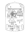
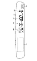
- FIG. 1 is an overall block diagram of a vehicle according to an embodiment. It is a figure which shows the structure of the meter mounted in the vehicle which concerns on this Embodiment. It is a functional block diagram of ECU mounted in the vehicle which concerns on this Embodiment. It is a collinear diagram for demonstrating operation
- the vehicle 1 includes an engine 10, a drive shaft 16, a first motor generator (hereinafter referred to as a first MG) 20, a second motor generator (hereinafter referred to as a second MG) 30, and a power split device 40. , A speed reducer 58, a PCU (Power Control Unit) 60, a battery 70, a drive wheel 80, a start switch 150, an ECU (Electronic Control Unit) 200, a meter 300, and a notification device 320.
- a first motor generator hereinafter referred to as a first MG
- a second motor generator hereinafter referred to as a second MG
- a speed reducer 58 a PCU (Power Control Unit) 60, a battery 70, a drive wheel 80, a start switch 150, an ECU (Electronic Control Unit) 200, a meter 300, and a notification device 320.
- the vehicle 1 travels by driving force output from at least one of the engine 10 and the second MG 30.
- the power generated by the engine 10 is divided into two paths by the power split device 40.
- One of the two routes is a route transmitted to the drive wheel 80 via the speed reducer 58, and the other route is a route transmitted to the first MG 20.
- the first MG 20 and the second MG 30 are, for example, three-phase AC rotating electric machines.
- First MG 20 and second MG 30 are driven by PCU 60.
- the first MG 20 has a function as a generator that generates power using the power of the engine 10 divided by the power split device 40 and charges the battery 70 via the PCU 60. Further, first MG 20 receives electric power from battery 70 and rotates a crankshaft that is an output shaft of engine 10. Thus, the first MG 20 has a function as a starter that starts the engine 10.
- the second MG 30 has a function as a driving motor that applies driving force to the driving wheels 80 using at least one of the electric power stored in the battery 70 and the electric power generated by the first MG 20. Second MG 30 also has a function as a generator for charging battery 70 via PCU 60 using electric power generated by regenerative braking.
- the engine 10 is an internal combustion engine such as a gasoline engine or a diesel engine.
- the engine 10 includes a plurality of cylinders 102, a fuel injection device 104 that supplies fuel to each of the plurality of cylinders 102, and an ignition device 106 that ignites the fuel in the plurality of cylinders 102.
- the fuel injection device 104 injects an appropriate amount of fuel to each cylinder at an appropriate time, or stops fuel injection to each cylinder.
- the ignition device 106 sparks spark plugs provided in each cylinder at an appropriate time based on the control signal S1 from the ECU.
- the engine 10 is provided with an engine rotation speed sensor 11 for detecting the rotation speed of the crankshaft of the engine 10 (hereinafter referred to as engine rotation speed) Ne.
- the engine rotation speed sensor 11 transmits a signal indicating the detected engine rotation speed Ne to the ECU 200.
- the power split device 40 mechanically connects each of the three elements of the drive shaft 16 for rotating the drive wheels 80, the output shaft of the engine 10, and the rotary shaft of the first MG 20.
- the power split device 40 enables transmission of power between the other two elements by using any one of the three elements described above as a reaction force element.
- the rotation shaft of second MG 30 is connected to drive shaft 16.
- the power split device 40 is a planetary gear mechanism including a sun gear 50, a pinion gear 52, a carrier 54, and a ring gear 56.
- the pinion gear 52 is meshed with each of the sun gear 50 and the ring gear 56.
- the carrier 54 supports the pinion gear 52 so as to be capable of rotating, and is connected to the crankshaft of the engine 10.
- Sun gear 50 is coupled to the rotation shaft of first MG 20.
- Ring gear 56 is coupled to the rotation shaft of second MG 30 and reduction gear 58 via drive shaft 16.
- Reduction gear 58 transmits power from power split device 40 and second MG 30 to drive wheels 80. Reducer 58 transmits the reaction force from the road surface received by drive wheels 80 to power split device 40 and second MG 30.
- PCU 60 converts the DC power stored in battery 70 into AC power for driving first MG 20 and second MG 30.
- PCU 60 includes a converter and an inverter (both not shown) controlled based on control signal S2 from ECU 200.
- the converter boosts the voltage of the DC power received from battery 70 and outputs it to the inverter.
- the inverter converts the DC power output from the converter into AC power and outputs the AC power to first MG 20 and / or second MG 30.
- first MG 20 and / or second MG 30 are driven using the electric power stored in battery 70.
- the inverter converts AC power generated by the first MG 20 and / or the second MG 30 into DC power and outputs the DC power to the converter.
- the converter steps down the voltage of the DC power output from the inverter and outputs the voltage to battery 70. Thereby, battery 70 is charged using the electric power generated by first MG 20 and / or second MG 30. Note that the converter may be omitted.
- the battery 70 is a power storage device and a rechargeable DC power source.
- a secondary battery such as nickel metal hydride or lithium ion is used.
- the voltage of the battery 70 is about 200V, for example.
- Battery 70 may be charged using electric power supplied from an external power source (not shown) in addition to being charged using electric power generated by first MG 20 and / or second MG 30 as described above.
- the battery 70 is not limited to a secondary battery, but may be a battery capable of generating a DC voltage, such as a capacitor, a solar battery, or a fuel battery.
- the battery 70 includes a battery temperature sensor 156 for detecting the battery temperature TB of the battery 70, a current sensor 158 for detecting the current IB of the battery 70, and a voltage sensor 160 for detecting the voltage VB of the battery 70. And are provided.
- the battery temperature sensor 156 transmits a signal indicating the battery temperature TB to the ECU 200.
- Current sensor 158 transmits a signal indicating current IB to ECU 200.
- Voltage sensor 160 transmits a signal indicating voltage VB to ECU 200.
- the start switch 150 is, for example, a push-type switch.
- the start switch 150 may be configured to insert a key into a key cylinder and rotate it to a predetermined position.
- Start switch 150 is connected to ECU 200.
- start switch 150 transmits signal ST to ECU 200.
- the ECU200 judges that it received the start instruction, for example, when signal ST is received when the system of vehicle 1 is a stop state, and makes the system of vehicle 1 shift from a stop state to a start state. Further, when the signal ST is received when the system of the vehicle 1 is in the activated state, the ECU 200 determines that a stop instruction has been received, and shifts the system of the vehicle 1 from the activated state to the stopped state.
- the start switch 150 when the system of the vehicle 1 is in an activated state, it is referred to as an IG-off operation, and when the system of the vehicle 1 is in a stopped state, the occupant operates the start switch 150. This is called IG on operation.
- the plurality of devices are in an operable state by supplying power to the plurality of devices necessary for the vehicle 1 to travel.
- some devices are stopped by supplying power to some of the plurality of devices necessary for the vehicle 1 to travel. Will stop operating.
- the meter 300 includes a first display unit 302 for displaying a mark having a predetermined shape, a second display unit 304 for displaying the remaining amount of fuel, and the speed of the vehicle 1.
- the mark having a predetermined shape is a “READY” mark.
- the first display unit 302 notifies the occupant of the state of the vehicle in either one of the first mode and the second mode. Specifically, the first display unit 302 notifies the occupant that the vehicle 1 is in the travel preparation state, with the mode in which the “READY” mark is blinking as the first mode. Further, the first display unit 302 notifies the occupant that the vehicle 1 is in a travelable state, with the mode in which the “READY” mark is always lit as the second mode.
- the vehicle 1 being in a travelable state refers to a state in which the vehicle 1 can start traveling, for example, when an occupant depresses an accelerator pedal.
- the vehicle 1 being in the travel preparation state is a state in which an operation for making the vehicle 1 ready to travel is being performed.
- the vehicle 1 is in response to an IG-on operation performed on the start switch 150. In this state, whether or not there is an abnormality in the system 1 is being checked.
- the equipment necessary for starting the engine 10 is in an operable state.
- the configuration of the meter 300 is not limited to the configuration shown in FIG.
- Each of the first display unit 302 to the fifth display unit 310 is turned on or off based on the control signal S3 from the ECU 200, displays information, or updates the displayed information.
- the notification device 320 is, for example, a sound generation device or a display device.
- the sound generator may generate a sound or may generate a warning sound.
- the display device may be, for example, the meter 300, an LCD (Liquid Crystal Display) provided at a position different from the meter 300, or an indicator provided at a position different from the meter 300. Also good.
- the notification device 320 may be, for example, an indicator that is provided in the start switch 150 and changes the display color in accordance with an operation on the start switch 150.
- the indicator may change the display color so that when the IG is turned off, the indicator color is turned on when the IG is turned off or the ACC is turned on, and the indicator color is turned on when the IG is turned on.
- the notification device 320 notifies the occupant of various information in a predetermined manner based on the control signal S4 from the ECU 200.
- the predetermined mode includes, for example, an always-on state of the indicator, a blinking state of the indicator, an unlit state of the indicator, an audio warning, a warning display, and the like.
- the first resolver 12 detects the rotational speed Nm1 of the first MG 20.
- the first resolver 12 transmits a signal indicating the detected rotation speed Nm1 to the ECU 200.
- the second resolver 13 detects the rotational speed Nm2 of the second MG 30.
- the second resolver 13 transmits a signal indicating the detected rotation speed Nm2 to the ECU 200.
- the wheel speed sensor 14 detects the rotational speed Nw of the drive wheel 80.
- the wheel speed sensor 14 transmits a signal indicating the detected rotation speed Nw to the ECU 200.
- ECU 200 calculates vehicle speed V based on the received rotational speed Nw.
- ECU 200 may calculate vehicle speed V based on rotation speed Nm2 of second MG 30 instead of rotation speed Nw.
- the ECU 200 generates a control signal S1 for controlling the engine 10 and outputs the generated control signal S1 to the engine 10.
- ECU 200 also generates a control signal S2 for controlling PCU 60 and outputs the generated control signal S2 to PCU 60.
- the ECU 200 controls the entire hybrid system, that is, the charging / discharging state of the battery 70 and the operating states of the engine 10, the first MG 20 and the second MG 30 so that the vehicle 1 can operate most efficiently by controlling the engine 10, the PCU 60, and the like. .
- ECU 200 calculates a required power corresponding to the amount of depression of an accelerator pedal (not shown) provided in the driver's seat. ECU 200 controls the torque of first MG 20 and second MG 30 and the output of engine 10 in accordance with the calculated required power.
- the vehicle 1 when the engine 10 is inefficient at the time of starting or running at a low speed, the vehicle 1 travels only by the second MG 30. Further, during normal travel, for example, the power split device 40 divides the power of the engine 10 into two paths of power.
- the drive wheel 80 is directly driven by one power.
- the first MG 20 is driven with the other power to generate power.
- ECU 200 drives second MG 30 using the generated electric power. In this way, driving of the driving wheel 80 is performed by driving the second MG 30.
- the second MG 30 driven by the rotation of the drive wheel 80 functions as a generator to perform regenerative braking.
- the electric power recovered by regenerative braking is stored in the battery 70.
- ECU 200 increases the output of engine 10 to increase the first MG 20 when the remaining capacity of the power storage device (described in the following description as SOC (State of Charge)) decreases and charging is particularly necessary. Increase the amount of power generated by Thereby, the SOC of the battery 70 is increased.
- the ECU 200 may perform control to increase the driving force from the engine 10 as necessary even during low-speed traveling. For example, the battery 70 needs to be charged as described above, an auxiliary machine such as an air conditioner is driven, or the temperature of the cooling water of the engine 10 is raised to a predetermined temperature.
- the ECU 200 determines the input power allowed when the battery 70 is charged based on the battery temperature TB and the current SOC (in the following description, “charging power upper limit value”). Output power (to be described as “discharge power upper limit value Wout” in the following description). For example, when the current SOC decreases, discharge power upper limit Wout is set to be gradually lower. On the other hand, when the current SOC increases, charging power upper limit value Win is set to gradually decrease.
- the secondary battery used as the battery 70 has a temperature dependency in which the internal resistance increases at a low temperature. Further, at a high temperature, it is necessary to prevent the temperature from excessively rising due to further heat generation. For this reason, it is preferable that each of the discharge power upper limit value Wout and the charge power upper limit value Win is lowered when the battery temperature TB is low and high. ECU 200 sets charge power upper limit value Win and discharge power upper limit value Wout by using, for example, a map or the like according to battery temperature TB and the current SOC.
- the IG-off operation may be mistakenly performed by a passenger during traveling, and the system of the vehicle 1 may stop.
- the occupant may not be able to recognize the system restart status. This is because it is unknown whether an operation for restarting the system has been accepted.
- ECU 200 when ECU 200 receives a start instruction after receiving a stop instruction from start switch 150 while vehicle 1 is traveling, it is determined that the start instruction has been received in the first mode by meter 300 or It has a feature in that a passenger is notified using the notification device 320.
- FIG. 3 shows a functional block diagram of ECU 200 mounted on vehicle 1 according to the present embodiment.
- ECU 200 includes a request determination unit 202, a start necessity determination unit 204, a meter control unit 206, a rotation speed determination unit 208, a start possibility determination unit 210, and a start completion determination unit 212.
- the request determination unit 202 determines whether or not a request for restarting the system of the vehicle 1 has been received while the vehicle 1 is traveling. Specifically, the request determination unit 202 determines whether or not the IG-on operation has been performed after the IG-off operation is performed while the vehicle 1 is traveling, based on the ST signal from the start switch 150. The request determination unit 202 may turn on the restart request determination flag when receiving a request for restarting the system of the vehicle 1 while the vehicle 1 is traveling, for example.
- the start necessity determination unit 204 determines whether the engine 10 needs to be started.
- the start necessity determination unit 204 determines whether or not the engine 10 needs to be started based on, for example, the required power or the SOC of the battery 70.
- the required power is calculated based on the vehicle speed V and the like in addition to the amount of depression of the accelerator pedal described above.
- the required power may be calculated from, for example, a map indicating the relationship between the vehicle speed V, the accelerator pedal depression amount, and the required power.
- the start necessity determination unit 204 determines that the engine 10 needs to be started when the calculated required power cannot be satisfied by the output of the second MG 30. Alternatively, the start necessity determination unit 204 needs to start the engine 10 in order to perform power generation using the first MG 20 when the SOC of the battery 70 falls below a threshold value for determining whether the engine 10 needs to be started. It is determined that
- the start necessity determination unit 204 determines, for example, whether the engine 10 needs to be started when the restart request determination flag is on, and determines that the engine 10 needs to be started. In this case, the start necessity determination flag may be turned on.
- the meter control unit 206 performs lighting control on the “READY” mark on the first display unit 302 in order to notify the occupant that the activation instruction has been received based on the determination result of the start necessity determination unit 204.
- the meter control unit 206 generates a control signal S3 based on the determination result of the start necessity determination unit 204 and transmits it to the meter 300.
- the meter control unit 206 controls the meter 300 so that the “READY” mark is always lit when the start necessity determination unit 204 determines that the start of the engine 10 is not necessary.
- the meter control unit 206 controls the meter 300 so that the “READY” mark blinks.
- the meter control unit 206 shifts the “READY” mark from the blinking state to the constantly lit state when the start completion determination unit 212 described later determines that the engine 10 has been started. For example, the meter control unit 206 may shift the “READY” mark from the blinking state to the constantly lit state when a later-described start completion determination flag changes from the off state to the on state.
- the meter control unit 206 determines that the “READY” mark is always lit when the start necessity determination flag is off, and the “READY” mark when the start necessity determination flag is on.
- the meter 300 may be controlled so that is in a blinking state.
- Rotational speed determination unit 208 determines whether or not the rotational speed Ne of the engine 10 is equal to or lower than a predetermined rotational speed Ne (0).
- the predetermined rotation speed Ne (0) or less means that the rotation speed is within the rotation speed region of the engine 10 that cannot be cranked using the first MG 20.
- the engine 10 stops for some reason while driving at high speed, the engine may not be restarted immediately.
- the case where the vehicle 1 is traveling at high speed is assumed as shown by the solid line in the alignment chart of FIG.
- the left vertical axis among the three vertical axes of the alignment chart shown in FIG. 4 indicates the rotational speed of the sun gear 50, that is, the rotational speed Nm1 of the first MG 20.
- the vertical axis at the center of the alignment chart shown in FIG. 4 indicates the rotational speed of the carrier 54, that is, the engine rotational speed Ne.
- the vertical axis on the right side of the alignment chart shown in FIG. 4 indicates the rotational speed of the ring gear 56, that is, the rotational speed Nm2 of the second MG 30.
- the rotational speed Nm1 of the first MG 20 When the vehicle 1 travels, the rotational speed Nm1 of the first MG 20, the engine rotational speed Ne, and the rotational speed Nm2 of the second MG 30 maintain a relationship that is connected by a single straight line on the alignment chart of FIG. Thus, the rotational speeds Nm1, Ne, and Nm2 of the elements change.
- the rotation speed Nm1 of the first MG 20 is Nm1 (0)
- the engine rotation speed Ne is Ne (1)
- the rotation speed Nm2 of the second MG 30 is Nm2 (0).
- the first MG 20 generates power in the process of increasing the rotation speed of the first MG 20 from Nm1 (1) to Nm1 (0). Therefore, when charging is limited due to the SOC of battery 70 being higher than the normal SOC range, that is, when charging power upper limit Win is lower than when SOC is within the normal SOC range. The first MG 20 may not be able to generate power. As a result, the engine 10 may not be restarted immediately.
- the determination of whether or not the engine rotational speed Ne is equal to or lower than the predetermined rotational speed Ne (0) means determination of whether or not the engine 10 can be started immediately using the first MG 20.
- the engine rotational speed Ne being equal to or lower than the predetermined rotational speed Ne (0) means that the engine 10 cannot be started immediately using the first MG 20.
- the predetermined rotational speed Ne (0) is a threshold value of the engine rotational speed Ne for determining whether or not the engine 10 can be started immediately using the first MG 20.
- the rotational speed determination unit 208 determines, for example, whether or not the engine rotational speed Ne is equal to or lower than a predetermined rotational speed Ne (0) when the start necessity determination flag is on, and the engine rotational speed Ne. Is equal to or less than the predetermined rotation speed Ne (0), the rotation speed determination flag may be turned on.
- the startability determination unit 210 determines whether the engine 10 can be started. Specifically, start possibility determination unit 210 determines whether or not vehicle speed V is within a speed range in which engine 10 can be started using first MG 20 (that is, whether or not vehicle speed V is equal to or lower than threshold value V (0)). Or not). The startability determination unit 210 determines that the engine 10 can be started when the vehicle speed V is within a speed range where the engine 10 can be started using the first MG 20. The startability determination unit 210 may turn on a startability determination flag when the engine 10 can be started, for example.
- the start completion determination unit 212 determines whether or not the engine 10 has been started. Specifically, the start completion determination unit 212 determines that the start of the engine 10 is completed when the engine rotation speed Ne is higher than a predetermined rotation speed Ne (2) indicating that the engine 10 is started. . Note that the start completion determination unit 212 may turn on a completion determination flag when the start of the engine 10 is completed, for example.
- the predetermined rotational speed Ne (2) indicating that the engine 10 is started is, for example, a rotational speed at which the engine 10 can complete explosion (can be operated independently).
- the request determination unit 202, the start necessity determination unit 204, the meter control unit 206, the rotation speed determination unit 208, the start possibility determination unit 210, and the start completion determination unit 212 are all included.
- the CPU of the ECU 200 functions as software, which is realized by executing a program stored in the memory, it may be realized by hardware. Such a program is recorded on a storage medium and mounted on the vehicle.
- step (hereinafter, step is referred to as S) 100 ECU 200 determines whether or not there is a system restart request while vehicle 1 is traveling. If there is a request to restart the system of vehicle 1 while vehicle 1 is traveling (YES in S100), the process proceeds to S102. If not (NO in S100), the process returns to S100.
- ECU 200 determines whether or not engine 10 needs to be started. Since the method for determining whether or not it is necessary to start engine 10 is as described above, detailed description thereof will not be repeated. If it is necessary to start engine 10 (YES in S102), the process proceeds to S104. If not (NO in S102), the process proceeds to S116.
- the ECU 200 controls the meter 300 so that the “READY” mark on the first display unit 302 is in a blinking state.
- ECU 200 determines whether engine rotation speed Ne is equal to or lower than a predetermined rotation speed Ne (0). If engine rotation speed Ne is equal to or lower than predetermined rotation speed Ne (0) (YES in S106), the process proceeds to S108. If not (NO in S106), the process proceeds to S110.
- ECU 200 determines whether or not engine 10 can be started. Specifically, ECU 200 determines that engine 10 can be started when vehicle speed V is equal to or lower than predetermined vehicle speed V (0). If engine 10 can be started (YES in S108), the process proceeds to S110. If not (NO in S108), the process returns to S108.
- the ECU 200 starts the engine 10. Specifically, ECU 200 uses first MG 20 to increase engine 10 to a rotational speed at which an initial explosion is possible, and performs fuel injection control and ignition control.
- ECU 200 determines whether or not start of engine 10 has been completed. If it is determined that start of engine 10 has been completed (YES in S112), the process proceeds to S114. If not (NO in S112), the process returns to S112.
- the ECU 200 controls the meter 300 so that the “READY” mark shifts from the blinking state to the constantly lit state.
- ECU 200 controls meter 300 so that the “READY” mark is always lit.
- the vehicle when the engine 10 is stopped and the restart is requested after the engine 10 is stopped during traveling, When the “READY” mark on the 1 display unit 302 is in a blinking state, the occupant can recognize that a request for restarting the system of the vehicle 1 has been accepted. Therefore, it is possible to provide a vehicle and a vehicle control method that allow the occupant to recognize the system restart status.
- the vehicle 1 having the driving wheel 80 as the front wheel is shown as an example, but the driving method is not particularly limited thereto.
- the vehicle 1 may have a rear wheel as a driving wheel.
- the vehicle 1 may be a vehicle in which the second MG 30 in FIG. 1 is omitted.
- vehicle 1 may be a vehicle in which second MG 30 in FIG. 1 is coupled to a drive shaft for driving rear wheels instead of front wheel drive shaft 16.
- a speed change mechanism may be provided between drive shaft 16 and speed reducer 58 or between drive shaft 16 and second MG 30.
- the vehicle 1 may be configured to omit the second MG 30, connect the rotation shaft of the first MG 20 directly to the output shaft of the engine 10, and include a transmission having a clutch instead of the power split device 40.
- the ECU 200 has been described as one ECU, but two or more ECUs may be used.
- the operation of ECU 200 in FIG. 1 may be shared between an engine ECU for controlling engine 10 and a hybrid ECU for controlling PCU 60.
- the meter control unit 206 in FIG. 3 may notify the occupant that the activation instruction has been received using the notification device 320 instead of the first display unit 302.
- the notification device 320 is a sound generation device
- the meter control unit 206 may notify an occupant that a start-up instruction has been received by generating a warning sound or sound.
- the meter control unit 206 changes the lighting color of the indicator to a predetermined color different from the normal color (when an activation instruction is given while the vehicle 1 is stopped). The occupant may be notified that the activation instruction has been accepted. The meter control unit 206 may notify the occupant that the start instruction has been received by increasing or decreasing the luminance of the display device continuously or stepwise. The meter control unit 206 may display on the LCD that the start instruction has been received and notify the occupant accordingly.
- the meter control unit 206 may generate the control signal S4 based on the determination result of the start necessity determination unit 204 and transmit it to the notification device 320.
- the meter control unit 206 may notify the occupant that each of the meter 300 and the notification device 320 has received an instruction to start the system of the vehicle 1 during traveling.
- the first operation is completed until the start of the engine 10 is completed.
- the “READY” mark on the display unit 302 has been described as blinking. However, for example, the blinking speed may be changed in accordance with the startup status of the system.
- the first blinking speed from when it is determined that the engine 10 needs to be started to when it is determined that the engine 10 can be started, and when the engine 10 can be started are determined.
- the second blinking speed during the period from the start to the completion of the start of the engine 10 may be made different. For example, by making the first blinking speed faster or slower than the second blinking speed, the occupant can recognize that the system startup process is in progress.
- the rotational speed determination unit 208 can start the engine 10 when, for example, the predicted value of the generated power generated when starting the engine 10 at the current vehicle speed is within the range of charging power acceptable by the battery 70. It is determined that
- the ECU 200 when a restart of the system of the vehicle 1 is requested during traveling, the ECU 200 does not check the system, but determines whether or not the engine 10 needs to be started.
- the “” mark has been described as being constantly lit or blinking, but is not limited to such an operation.
- the ECU 200 causes the “READY” mark to blink and checks the system of the vehicle 1 before starting the engine 10.
- the “READY” mark may be continuously lit or blinked.
Abstract
Description
また、エンジン10の始動が必要でないと判定される場合には(S102にてNO)、第1表示部302の「READY」マークが常時点灯状態となり(S116)、車両1は、エンジン10を停止させた状態で第2MG30を用いて走行する。
Claims (9)
- 車両(1)のシステムの起動状態を乗員に告知するための告知部(300、302)と、
前記車両(1)の前記システムの停止指示および起動指示を前記乗員から受けるための入力部(150)と、
前記車両(1)の走行中に前記停止指示を前記入力部(150)に受けた後に前記起動指示を前記入力部(150)に受けた場合には、第1態様で前記起動指示を受け付けたことを前記告知部(300、320)を用いて前記乗員に告知するための制御部(200)とを含む、車両。 - 前記車両(1)は、内燃機関(10)をさらに含み、
前記第1態様は、前記内燃機関(10)を始動させるために必要な機器が作動可能な状態であることを前記乗員に告知するための態様である、請求項1に記載の車両。 - 前記第1態様は、前記車両(1)が走行準備状態であることを前記乗員に告知するための態様であって、
前記制御部(200)は、前記走行中に前記停止指示を前記入力部(150)に受けた後に、前記起動指示を前記入力部(150)に受けた場合であって、かつ、前記内燃機関(10)の始動が要求される場合には、前記内燃機関(10)が始動するまで前記第1態様で前記起動指示を受け付けたことを前記告知部(300、320)を用いて前記乗員に告知する、請求項2に記載の車両。 - 前記車両(1)は、駆動用回転電機(30)と内燃機関(10)とをさらに含み、
前記制御部(200)は、前記走行中に前記停止指示を前記入力部(150)に受けた後に、前記起動指示を前記入力部(150)に受けた場合であって、かつ、前記内燃機関(10)を停止させた状態で前記駆動用回転電機(30)によって前記車両(1)が走行する場合には、前記第1態様と異なる第2態様で前記告知部(300、320)を用いて前記乗員に告知する、請求項1に記載の車両。 - 前記第1態様は、予め定められた形状のマークを点滅させる態様であって、
前記第2態様は、前記マークを常時点灯させる態様である、請求項4に記載の車両。 - 前記第1態様は、音によって前記起動指示を受け付けたことを前記乗員に認識させる態様であって、
前記第2態様は、音によって前記車両(1)が走行可能状態であることを前記乗員に認識させる態様である、請求項4に記載の車両。 - 前記告知部(300、320)は、
前記乗員からの前記起動指示を前記入力部(150)に受けたことに応じて、前記起動指示を受け付けたことを前記第1態様で前記乗員に表示するための第1表示部(300)と、
前記第1表示部(300)とは異なる位置に設けられ、前記車両(1)が走行可能状態であることを前記第2態様で前記乗員に表示するための第2表示部(320)とを含む、請求項4に記載の車両。 - 前記車両(1)は、
駆動輪(80)を回転させるための駆動軸(16)と、
内燃機関(10)と、
第1回転電機(20)と、
前記駆動軸(16)、前記内燃機関(10)の出力軸および前記第1回転電機(20)の回転軸の三要素の各々を機械的に連結し、前記三要素のうちのいずれか一つを反力要素とすることによって、他の2つの要素間での動力伝達が可能な動力伝達装置(40)とをさらに含む、請求項1に記載の車両。 - 車両(1)のシステムの起動状態を乗員に告知するための告知部(300、320)が搭載された前記車両(1)に用いられる車両用制御方法であって、
前記車両(1)の前記システムの停止指示および起動指示のうちのいずれか一方の指示を前記乗員から受けたか否かを判定するステップと、
前記車両(1)の走行中に前記停止指示を受けた後に前記起動指示を受けた場合には、第1態様で前記起動指示を受け付けたことを前記告知部(300、320)を用いて前記乗員に告知するステップとを含む、車両用制御方法。
Priority Applications (4)
| Application Number | Priority Date | Filing Date | Title |
|---|---|---|---|
| CN2011800695594A CN103442926A (zh) | 2011-03-24 | 2011-03-24 | 车辆及车辆用控制方法 |
| PCT/JP2011/057151 WO2012127677A1 (ja) | 2011-03-24 | 2011-03-24 | 車両および車両用制御方法 |
| JP2013505744A JPWO2012127677A1 (ja) | 2011-03-24 | 2011-03-24 | 車両および車両用制御方法 |
| US14/006,632 US20140002256A1 (en) | 2011-03-24 | 2011-03-24 | Vehicle and control method for vehicle |
Applications Claiming Priority (1)
| Application Number | Priority Date | Filing Date | Title |
|---|---|---|---|
| PCT/JP2011/057151 WO2012127677A1 (ja) | 2011-03-24 | 2011-03-24 | 車両および車両用制御方法 |
Publications (1)
| Publication Number | Publication Date |
|---|---|
| WO2012127677A1 true WO2012127677A1 (ja) | 2012-09-27 |
Family
ID=46878870
Family Applications (1)
| Application Number | Title | Priority Date | Filing Date |
|---|---|---|---|
| PCT/JP2011/057151 WO2012127677A1 (ja) | 2011-03-24 | 2011-03-24 | 車両および車両用制御方法 |
Country Status (4)
| Country | Link |
|---|---|
| US (1) | US20140002256A1 (ja) |
| JP (1) | JPWO2012127677A1 (ja) |
| CN (1) | CN103442926A (ja) |
| WO (1) | WO2012127677A1 (ja) |
Cited By (3)
| Publication number | Priority date | Publication date | Assignee | Title |
|---|---|---|---|---|
| JP2013252824A (ja) * | 2012-06-08 | 2013-12-19 | Toyota Motor Corp | 車両 |
| WO2015052777A1 (ja) * | 2013-10-08 | 2015-04-16 | 日産自動車株式会社 | ハイブリッド車両の制御装置 |
| US10864921B2 (en) | 2018-11-26 | 2020-12-15 | Honda Motor Co., Ltd. | Onboard apparatus |
Families Citing this family (5)
| Publication number | Priority date | Publication date | Assignee | Title |
|---|---|---|---|---|
| JP5665231B2 (ja) * | 2011-06-28 | 2015-02-04 | 本田技研工業株式会社 | エンジン回転数表示装置 |
| JP6319113B2 (ja) * | 2015-01-19 | 2018-05-09 | 株式会社デンソー | 電力制御装置 |
| TWI577981B (zh) * | 2015-08-27 | 2017-04-11 | 久朝企業有限公司 | 交通工具的即時監測系統 |
| DE102017207436B4 (de) * | 2017-05-03 | 2019-03-14 | Volkswagen Aktiengesellschaft | Verfahren zum Betreiben einer Beleuchtung eines Kraftfahrzeugs sowie Kraftfahrzeug zur Durchführung des Verfahrens |
| KR102490735B1 (ko) * | 2017-10-30 | 2023-01-20 | 현대자동차주식회사 | 자동차의 표시 장치 |
Citations (2)
| Publication number | Priority date | Publication date | Assignee | Title |
|---|---|---|---|---|
| JP2002332942A (ja) * | 2001-05-10 | 2002-11-22 | Toyota Motor Corp | 機関始動中信号手段を有する自動車 |
| JP2007203835A (ja) * | 2006-01-31 | 2007-08-16 | Toyota Motor Corp | ハイブリッド車両の制御装置 |
Family Cites Families (24)
| Publication number | Priority date | Publication date | Assignee | Title |
|---|---|---|---|---|
| US6275231B1 (en) * | 1997-08-01 | 2001-08-14 | American Calcar Inc. | Centralized control and management system for automobiles |
| JP2000080957A (ja) * | 1998-09-07 | 2000-03-21 | Daihatsu Motor Co Ltd | 回転角センサの信号判別方法 |
| US7253746B2 (en) * | 2004-03-10 | 2007-08-07 | Fujitsu Ten Limited | Vehicle-presence notifying apparatus and vehicle-presence notifying method |
| JP4437468B2 (ja) * | 2004-12-06 | 2010-03-24 | 富士通テン株式会社 | 車両用電子制御装置 |
| JP4250149B2 (ja) * | 2005-05-10 | 2009-04-08 | 株式会社デンソー | エンジン始動制御システム |
| JP4528238B2 (ja) * | 2005-09-30 | 2010-08-18 | 株式会社クボタ | 作業車の車速制御構造 |
| JP4155321B2 (ja) * | 2006-09-25 | 2008-09-24 | トヨタ自動車株式会社 | ハイブリッド車両の表示装置、ハイブリッド車両、およびハイブリッド車両の表示方法 |
| JP4987551B2 (ja) * | 2007-04-19 | 2012-07-25 | 富士通テン株式会社 | エコランシステム、制御プログラム及びエコラン状態報知装置 |
| CN101092140A (zh) * | 2007-07-12 | 2007-12-26 | 奇瑞汽车有限公司 | 弱混合动力汽车的控制系统 |
| JP4321648B2 (ja) * | 2007-11-08 | 2009-08-26 | トヨタ自動車株式会社 | ハイブリッド車およびその制御方法 |
| DE102008039588B4 (de) * | 2007-12-12 | 2016-02-04 | GM Global Technology Operations LLC (n. d. Ges. d. Staates Delaware) | Hybridmaschinensteuersystem sowie Verfahren zum Steuern desselben |
| US20110017533A1 (en) * | 2009-07-24 | 2011-01-27 | International Truck Intellectual Property Company, Llc | Hybrid traction motor initiated remote start-stop system |
| US8924060B2 (en) * | 2010-04-07 | 2014-12-30 | Toyota Jidosha Kabushiki Kaisha | Control device for hybrid vehicle, and hybrid vehicle incorporating control device |
| WO2012086061A1 (ja) * | 2010-12-24 | 2012-06-28 | トヨタ自動車株式会社 | 車両および車両用制御方法 |
| CN103282256A (zh) * | 2010-12-27 | 2013-09-04 | 丰田自动车株式会社 | 混合动力车辆及其控制方法 |
| CN103328291B (zh) * | 2011-01-27 | 2016-08-24 | 丰田自动车株式会社 | 车辆及车辆用控制方法 |
| JP5598555B2 (ja) * | 2011-01-27 | 2014-10-01 | トヨタ自動車株式会社 | 車両および車両用制御方法 |
| JPWO2012105019A1 (ja) * | 2011-02-03 | 2014-07-03 | トヨタ自動車株式会社 | 車両および車両の制御方法 |
| CN103339419B (zh) * | 2011-02-04 | 2015-04-22 | 丰田自动车株式会社 | 车辆的控制装置 |
| WO2012120688A1 (ja) * | 2011-03-10 | 2012-09-13 | トヨタ自動車株式会社 | 車両制御装置 |
| US20140180522A1 (en) * | 2011-08-11 | 2014-06-26 | Toyota Jidosha Kabushiki Kaisha | Hybrid vehicle control device |
| JP5783255B2 (ja) * | 2011-09-02 | 2015-09-24 | トヨタ自動車株式会社 | 車両用エンジンの制御装置 |
| JP5871692B2 (ja) * | 2012-03-29 | 2016-03-01 | 本田技研工業株式会社 | 車両用トラクションコントロール表示装置 |
| JP6024584B2 (ja) * | 2013-04-19 | 2016-11-16 | トヨタ自動車株式会社 | ハイブリッド車両 |
-
2011
- 2011-03-24 CN CN2011800695594A patent/CN103442926A/zh active Pending
- 2011-03-24 US US14/006,632 patent/US20140002256A1/en not_active Abandoned
- 2011-03-24 JP JP2013505744A patent/JPWO2012127677A1/ja active Pending
- 2011-03-24 WO PCT/JP2011/057151 patent/WO2012127677A1/ja active Application Filing
Patent Citations (2)
| Publication number | Priority date | Publication date | Assignee | Title |
|---|---|---|---|---|
| JP2002332942A (ja) * | 2001-05-10 | 2002-11-22 | Toyota Motor Corp | 機関始動中信号手段を有する自動車 |
| JP2007203835A (ja) * | 2006-01-31 | 2007-08-16 | Toyota Motor Corp | ハイブリッド車両の制御装置 |
Cited By (3)
| Publication number | Priority date | Publication date | Assignee | Title |
|---|---|---|---|---|
| JP2013252824A (ja) * | 2012-06-08 | 2013-12-19 | Toyota Motor Corp | 車両 |
| WO2015052777A1 (ja) * | 2013-10-08 | 2015-04-16 | 日産自動車株式会社 | ハイブリッド車両の制御装置 |
| US10864921B2 (en) | 2018-11-26 | 2020-12-15 | Honda Motor Co., Ltd. | Onboard apparatus |
Also Published As
| Publication number | Publication date |
|---|---|
| US20140002256A1 (en) | 2014-01-02 |
| CN103442926A (zh) | 2013-12-11 |
| JPWO2012127677A1 (ja) | 2014-07-24 |
Similar Documents
| Publication | Publication Date | Title |
|---|---|---|
| WO2012127677A1 (ja) | 車両および車両用制御方法 | |
| JP4483989B2 (ja) | ハイブリッド車両 | |
| JP5598555B2 (ja) | 車両および車両用制御方法 | |
| US20140288757A1 (en) | Hybrid vehicle | |
| JP5652479B2 (ja) | 車両および車両用制御方法 | |
| JP6149806B2 (ja) | ハイブリッド車両 | |
| JP2008162491A (ja) | 車両およびその制御方法 | |
| JP5825115B2 (ja) | プラグインハイブリッド車両 | |
| JP2013141858A (ja) | ハイブリッド車両の制御装置 | |
| JP5644868B2 (ja) | 車両および車両の制御方法 | |
| JP6947051B2 (ja) | ハイブリッド自動車 | |
| JP5565256B2 (ja) | ハイブリッド自動車および情報出力方法 | |
| JP4957298B2 (ja) | ハイブリッド自動車およびその制御方法 | |
| JP2012176652A (ja) | 車両および車両用制御方法 | |
| JP5652546B2 (ja) | 車両および車両用制御方法 | |
| JP2012162097A (ja) | 車両 | |
| JP6361299B2 (ja) | ハイブリッド車両 | |
| JP5810580B2 (ja) | 車両および車両用制御方法 | |
| JP5700053B2 (ja) | 車両および車両用制御方法 | |
| WO2012105019A1 (ja) | 車両および車両の制御方法 | |
| JP7437364B2 (ja) | 表示制御装置 | |
| JP7403920B2 (ja) | 電動車両の制御装置 | |
| JP2024008640A (ja) | 表示制御装置 | |
| JP2013132945A (ja) | ハイブリッド車両の制御装置 | |
| JP2012236470A (ja) | 車両の制振制御装置 |
Legal Events
| Date | Code | Title | Description |
|---|---|---|---|
| 121 | Ep: the epo has been informed by wipo that ep was designated in this application |
Ref document number: 11861758 Country of ref document: EP Kind code of ref document: A1 |
|
| ENP | Entry into the national phase |
Ref document number: 2013505744 Country of ref document: JP Kind code of ref document: A |
|
| WWE | Wipo information: entry into national phase |
Ref document number: 14006632 Country of ref document: US |
|
| NENP | Non-entry into the national phase |
Ref country code: DE |
|
| 122 | Ep: pct application non-entry in european phase |
Ref document number: 11861758 Country of ref document: EP Kind code of ref document: A1 |