WO2012124628A1 - 車両用駆動力伝達装置 - Google Patents
車両用駆動力伝達装置 Download PDFInfo
- Publication number
- WO2012124628A1 WO2012124628A1 PCT/JP2012/056124 JP2012056124W WO2012124628A1 WO 2012124628 A1 WO2012124628 A1 WO 2012124628A1 JP 2012056124 W JP2012056124 W JP 2012056124W WO 2012124628 A1 WO2012124628 A1 WO 2012124628A1
- Authority
- WO
- WIPO (PCT)
- Prior art keywords
- diameter side
- clutch
- dry
- seal
- piston
- Prior art date
- Legal status (The legal status is an assumption and is not a legal conclusion. Google has not performed a legal analysis and makes no representation as to the accuracy of the status listed.)
- Ceased
Links
Images


Classifications
-
- F—MECHANICAL ENGINEERING; LIGHTING; HEATING; WEAPONS; BLASTING
- F16—ENGINEERING ELEMENTS AND UNITS; GENERAL MEASURES FOR PRODUCING AND MAINTAINING EFFECTIVE FUNCTIONING OF MACHINES OR INSTALLATIONS; THERMAL INSULATION IN GENERAL
- F16D—COUPLINGS FOR TRANSMITTING ROTATION; CLUTCHES; BRAKES
- F16D25/00—Fluid-actuated clutches
- F16D25/06—Fluid-actuated clutches in which the fluid actuates a piston incorporated in, i.e. rotating with the clutch
- F16D25/062—Fluid-actuated clutches in which the fluid actuates a piston incorporated in, i.e. rotating with the clutch the clutch having friction surfaces
- F16D25/063—Fluid-actuated clutches in which the fluid actuates a piston incorporated in, i.e. rotating with the clutch the clutch having friction surfaces with clutch members exclusively moving axially
- F16D25/0635—Fluid-actuated clutches in which the fluid actuates a piston incorporated in, i.e. rotating with the clutch the clutch having friction surfaces with clutch members exclusively moving axially with flat friction surfaces, e.g. discs
-
- F—MECHANICAL ENGINEERING; LIGHTING; HEATING; WEAPONS; BLASTING
- F16—ENGINEERING ELEMENTS AND UNITS; GENERAL MEASURES FOR PRODUCING AND MAINTAINING EFFECTIVE FUNCTIONING OF MACHINES OR INSTALLATIONS; THERMAL INSULATION IN GENERAL
- F16D—COUPLINGS FOR TRANSMITTING ROTATION; CLUTCHES; BRAKES
- F16D25/00—Fluid-actuated clutches
- F16D25/08—Fluid-actuated clutches with fluid-actuated member not rotating with a clutching member
- F16D25/082—Fluid-actuated clutches with fluid-actuated member not rotating with a clutching member the line of action of the fluid-actuated members co-inciding with the axis of rotation
- F16D25/087—Fluid-actuated clutches with fluid-actuated member not rotating with a clutching member the line of action of the fluid-actuated members co-inciding with the axis of rotation the clutch being actuated by the fluid-actuated member via a diaphragm spring or an equivalent array of levers
-
- F—MECHANICAL ENGINEERING; LIGHTING; HEATING; WEAPONS; BLASTING
- F16—ENGINEERING ELEMENTS AND UNITS; GENERAL MEASURES FOR PRODUCING AND MAINTAINING EFFECTIVE FUNCTIONING OF MACHINES OR INSTALLATIONS; THERMAL INSULATION IN GENERAL
- F16D—COUPLINGS FOR TRANSMITTING ROTATION; CLUTCHES; BRAKES
- F16D2300/00—Special features for couplings or clutches
- F16D2300/08—Details or arrangements of sealings not provided for in group F16D3/84
-
- F—MECHANICAL ENGINEERING; LIGHTING; HEATING; WEAPONS; BLASTING
- F16—ENGINEERING ELEMENTS AND UNITS; GENERAL MEASURES FOR PRODUCING AND MAINTAINING EFFECTIVE FUNCTIONING OF MACHINES OR INSTALLATIONS; THERMAL INSULATION IN GENERAL
- F16D—COUPLINGS FOR TRANSMITTING ROTATION; CLUTCHES; BRAKES
- F16D2300/00—Special features for couplings or clutches
- F16D2300/26—Cover or bell housings; Details or arrangements thereof
-
- Y—GENERAL TAGGING OF NEW TECHNOLOGICAL DEVELOPMENTS; GENERAL TAGGING OF CROSS-SECTIONAL TECHNOLOGIES SPANNING OVER SEVERAL SECTIONS OF THE IPC; TECHNICAL SUBJECTS COVERED BY FORMER USPC CROSS-REFERENCE ART COLLECTIONS [XRACs] AND DIGESTS
- Y02—TECHNOLOGIES OR APPLICATIONS FOR MITIGATION OR ADAPTATION AGAINST CLIMATE CHANGE
- Y02T—CLIMATE CHANGE MITIGATION TECHNOLOGIES RELATED TO TRANSPORTATION
- Y02T10/00—Road transport of goods or passengers
- Y02T10/60—Other road transportation technologies with climate change mitigation effect
- Y02T10/62—Hybrid vehicles
Definitions
- the present invention relates to a vehicle driving force transmission device that transmits power from a driving source such as an engine or a motor to a wheel via a clutch and a transmission, and more specifically, uses the power from the driving source as an input shaft of the transmission.
- the present invention relates to a structure of a hydraulic actuator for a dry clutch for transmission.
- the rotor of the electric motor is connected to the input shaft of the transmission, and a dry clutch is disposed between the input shaft and the engine for driving driving.
- the above electric motor is used to start the engine.
- the dry clutch interposed between the input shaft of the transmission and the engine is disposed in a non-lubricated dry space, is always urged to be engaged, and is released by supplying hydraulic pressure to the hydraulic actuator.
- the hydraulic actuator is disposed between a transmission and a clutch cover of a dry clutch, and the movement of a piston of the hydraulic actuator is transmitted to the dry clutch via a clutch arm penetrating the clutch cover.
- a leak oil recovery device has been devised to prevent leak oil from the piston arm sliding portion of the hydraulic actuator from leaking to the dry clutch side in the dry space and to collect the leak oil in the transmission. (Patent Document 1).
- the leak oil recovery device is provided with a partition elastic member in the clutch cover so as to partition the clutch arm and the dry clutch, and a seal between the cylinder housing and the clutch cover is sealed with a first seal member. The leaked oil from the piston arm sliding portion of the hydraulic actuator is returned to the transmission through the clearance formed between the cylinder housing and the clutch cover and the first recovery oil passage.
- the leak oil recovery device is a rotating member while preventing leak oil from the piston arm sliding member from leaking into the dry space for the dry clutch by a partition elastic member that closes the through hole portion for the piston arm.
- a first seal member seals a gap between the clutch cover and the cylinder housing, which is a stationary member, and a gap between the clutch cover and the cylinder housing extends from the bearing lubricating oil passage to the downstream side of the piston arm sliding portion.
- the leak oil is used as a single recovery oil passage and joins the first recovery oil passage and returns it to the transmission.
- the leak oil recovery device requires a space between the clutch cover sealed by the first seal member and the cylinder housing in addition to the partition elastic member, and is a large-scale device and is premised on a bearing lubricating oil passage.
- the application location is also limited.
- the present invention provides a vehicle driving force transmission device that recovers leak oil from a hydraulic actuator portion that operates a dry clutch with a small, particularly axially compact device, and solves the above-described problems. It is the purpose.
- the present invention includes a dry clutch (5) that is disposed in a dry space (D) and that connects and disconnects power between an engine output shaft (2a) and a transmission input shaft (7). (25) is stored in a wet environment (W) in which oil is enclosed, and the rotation of the input shaft (7) is shifted and output to the output unit (20) connected to the drive wheels (221, 22r).
- a hydraulic actuator (50) for operating the dry clutch (5) is disposed at a position facing the dry space (D) of the case (25a), The hydraulic actuator (50) is inserted in a cylinder portion (51) formed in the case (25a) and oil-tightly and slidably inserted into the cylinder portion by a first seal portion (55).
- the connecting member (56) has a second seal part (59) for sealing between the cylinder part (51), A space (57) formed by the back surface of the piston (52), the connecting member (56), and the cylinder part (51) sealed by the first seal part (55) and the second seal part (59). Is communicated with the case (25a) by the oil passage (61) in the transmission, and the oil in the space (57) leaked from the piston is removed by the oil passage (61).
- the case (25) of The present invention is a vehicle driving force transmission device.
- the cylinder portion (51) includes a bottom surface (51a), an annular outer diameter side flange (51b), and an inner diameter side flange (51c).
- the connecting member comprises a connecting plate (56) having a bent portion (56a) along the inner diameter side surface of the inner diameter side flange (51c),
- the second seal portion (59) is fixed to the outer diameter end of the connection plate (56), and seals between the outer diameter side flange portion (51b) and the inner diameter side surface thereof (59a),
- An inner seal (59b) that is fixed to the bent portion (56a) of the connecting plate (56) and seals between the inner diameter side surface of the inner diameter side flange (51c).
- the first seal portion (55) and the inner seal (59b) of the second seal portion (59) are arranged so as to overlap in the axial direction when viewed from the radial direction.
- the dry clutch (5) is a dry single plate clutch, and a clutch plate (40) connected to the input shaft (7) is urged and engaged with a spring (45) on the engine output shaft side,
- the connecting plate (56) has an outer diameter side (56b) of the bent portion (56a) extending in a radial direction on the dry clutch (5) side so that the piston rod (52a) is integral with the piston (52).
- the inner side (56c) of the bent portion (56a) extends in the radial direction on the case (25a) side and comes into contact with the release bearing (46) on the case (25a) side.
- the vehicle driving force transmission device (1) includes an electric motor (3),
- the rotor (35) of the electric motor is composed of a hybrid drive device that interlocks with the input shaft (7) of the transmission.
- the space formed by the back surface of the piston for operating the dry clutch, the connecting member, and the cylinder portion is sealed by the first seal portion and the second seal portion.
- the oil leaked from the sliding of the piston is stored in the space and returned to the lubricating space in the case by the oil passage, so that the leaked oil from the hydraulic actuator does not leak into the dry space that houses the dry clutch.
- dust in the dry space does not enter the hydraulic actuator, and the reliability of operation and operation of the dry clutch can be improved with a relatively simple device in which the second seal portion is provided on the connecting member. .
- the cylinder portion is composed of an annular flange portion on the outer diameter side and the inner diameter side
- the coupling member is composed of a connection plate having a bent portion along the inner diameter side surface of the inner diameter side flange portion. Therefore, it is possible to arrange the hydraulic actuator and the operation member of the dry clutch so as to overlap in the axial direction, shorten the axial dimension, make the operation part of the dry clutch compact, especially the axial dimension compactness Can be improved.
- the first seal portion of the piston that moves integrally and the inner seal of the second seal portion of the connecting member are arranged so as to overlap in the axial direction. Compactness can be achieved.
- the dry clutch is a dry single-plate clutch, and is always engaged by the biasing force of the spring, and the biasing force is released via the release bearing by supplying the hydraulic pressure of the hydraulic actuator. Therefore, the clutch is engaged with the spring biasing force on the side where the operating time of driving with the internal combustion engine is long, and the supply time of the working hydraulic pressure is short, so that energy can be saved.
- the present invention is applied to a hybrid drive device that includes an electric motor and engages the dry clutch by the electric motor to start an internal combustion engine, and compares the operation of the dry clutch by the hydraulic actuator. Even if the operation is performed at a high frequency, oil can be prevented from leaking from the hydraulic actuator into the dry space, and a highly reliable hybrid drive device can be provided while being a relatively simple device.
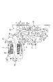
- the vehicle driving force transmission device is applied as a one-motor type hybrid driving device 1 and includes an internal combustion engine 2 and an electric motor 3 as driving sources as shown in FIG.
- the output shaft 2 a of the engine 2 is connected to the input shaft 7 via a dry clutch 5 and a damper spring 6.
- the rotor of the electric motor 3 is connected to a gear 11 provided on the input shaft 7 via an output gear 9 and an idler gear 10.
- the rotation of the input shaft 7 is shifted by the speed change mechanism 12 and transmitted to the counter drive gear 13 and further transmitted to the counter shaft 16 via the counter driven gear 15.
- the rotation of the counter shaft 16 is transmitted to the differential device 20 via the gear 17 and the differential mount gear 19, and is transmitted to the left and right drive wheels 22l and 22r via the left and right axle shafts 21l and 21r.
- the transmission mechanism 12 may be any type such as a stepped automatic transmission mechanism such as forward fourth speed, sixth speed, or eighth speed, or a continuously variable transmission mechanism such as a belt type or a cone ring type.
- the speed change mechanism 12, the counter shaft 16 and the differential device 20 are housed in a case as a speed change device.
- the electric motor 3 is also connected to the gears 9, 10, 11 in the case 25. It is stored with.
- the case 25 is a moist space (environment) W that is filled with lubricating oil and hydraulic oil.
- a clutch housing 26 is integrally formed on the front side of the case 25, the dry clutch 5 is accommodated in the clutch housing 26, and the front end of the clutch housing 26 is fixed to the internal combustion engine 2. .
- the inside of the clutch housing 25 is a dry (dry, non-wet, open) space D.
- the transmission in the case 25 is partitioned by the dry space D and the front wall 25a, and the clutch shaft 29 is supported by the bearing 30 and penetrates the boss portion 27 of the front wall 25a. It is sealed by.
- the clutch shaft 29 is spline-engaged with the input shaft 7 of the transmission (mechanism 12 or the like) in the case 25, the gear 11 is integrally formed, and is connected to the oil pump 32.
- the rotor shaft 35 a having the rotor 35 of the electric motor 3 is integrally formed with the gear 9 and is rotatably supported by the case 25 by bearings 65 and 65.
- the idler gear 10 is also rotatably supported on the case 25 by bearings 66 and 66, and the rotation of the rotor shaft 35 a is transmitted to the input shaft 7 through the gears 9, 10 and 11.
- the dry clutch 5 is a dry single-plate clutch having a single clutch plate 40 connected to the clutch shaft 29 via the damper spring 6.
- the clutch plate 40 has friction plates 40a and 40a attached to both sides thereof, and is positioned between a flywheel 41 and a pressure plate 42 that are integrally fixed to the engine output shaft 2a.
- a clutch cover 43 is fixed to the flywheel 41, and a pressure plate 42 is connected to the clutch cover 43 so as to be integral with the rotation direction and movable in the axial direction by a predetermined amount.
- a diaphragm spring 45 is supported at an intermediate portion of the tip end portion 43a of the clutch cover 43, and an outer diameter side end of the diaphragm spring 45 can abut against the pressure plate 42, and an inner diameter side end thereof is a clutch. It is in contact with a release bearing 46 which is an operation member.
- the release bearing 46 is supported by the boss 27 of the case front wall 25a so as to be rotatable and movable in the axial direction.
- the hydraulic actuator 50 for operating the dry clutch 5 according to the present invention is disposed on the outer diameter side of the release bearing 46 on the case front wall 25a.
- the hydraulic actuator 50 has a cylinder portion 51 and a piston 52 formed on the case front wall 25a.
- the cylinder portion 51 has an annular shape composed of an annular outer diameter side flange portion 51b and an inner diameter side flange portion 51c protruding from the bottom surface 51a toward the axial dry space D, and between the flange portions 51b and 51c,
- the piston 52 is sealed by a first seal portion 55 made of an O-ring and is slidably fitted.
- a hydraulic oil chamber 50a is formed between the piston and the cylinder portion bottom surface 51a.
- the piston 52 is integrally formed with a piston rod 52a that protrudes toward the dry space D, and a connecting plate 56 that is a connecting member connects the tip of the piston rod 52a and the release bearing 46.
- the connecting plate 56 has a bent portion 56a bent so that an intermediate portion extends in the axial direction, and an outer diameter side (portion) 56b of the bent portion extends in the radial direction on the dry clutch side to extend the piston rod 52a.
- An inner diameter side (portion) 56c of the bent portion 56a extends in the radial direction on the case side and contacts the release bearing 46 on the case side.
- a second seal portion 59 made of an elastic member such as rubber is fixed to the connecting plate 56, and the second seal portion 59 is in oil-tight sliding contact with the cylinder portion 51. Sealed by the first seal portion 55 and the second seal portion 59, a leak oil space 57 is formed by the back surface (rod side) of the piston 52, the connecting plate 56 and the cylinder portion 51.
- a piston rod 52a is integrally fixed to the piston 52 to constitute a piston. Alternatively, the rod may be formed integrally with the connecting plate toward the back surface of the piston, and the piston and the connecting plate may be interlocked.
- the bent portion 56 a of the connecting plate 56 extends in the axial direction along the inner peripheral surface of the inner diameter side flange 51 c of the cylinder portion 51.
- the second seal portion 59 includes an outer seal 59a fixed to the outer peripheral portion of the connecting plate outer diameter side portion 56b and an inner seal 59b fixed to the inner diameter side portion 56c side of the bent portion 56a.
- the seal 59a is in close contact with the inner peripheral surface of the cylinder portion outer diameter side flange portion 51b
- the inner seal 59b is in close contact with the inner diameter side surface of the cylinder portion inner diameter side flange portion 51c.
- the hydraulic oil chamber 50a of the hydraulic actuator 50 communicates with a valve via an oil passage 60 formed in the case 25, and hydraulic pressure is appropriately supplied.
- the leak oil space 57 communicates with a wet space W in which the transmission in the case 25 is accommodated by a leak oil recovery oil passage 61 formed through the case front wall 25a. 2 and 3 are development views, the leak oil recovery oil passage 61 is shown as being above the leak oil space 57, but the oil passage 61 is located below the space 57. Preferably it is in position.
- the case front wall 25a has a hydraulic actuator 50 and its inner side A recessed to the transmission side with respect to a portion B where the bearings 65 and 66 for supporting the rotor shaft 35a and the idler gear 10 are mounted.
- the axial space for the hydraulic actuator 50, the connecting plate 56, and the release bearing 46 is reduced.
- the hydraulic actuator 50 and the release bearing 46 are arranged so as to partially overlap in the axial direction when viewed from the radial direction, the axial dimension is shortened, and the first seal portion that moves further integrally. 55 and the inner seal 59b of the second seal portion are arranged so as to overlap in the axial direction to shorten the axial dimension.
- the vehicle is driven by the electric motor 3 when the vehicle starts and EV travels.
- a predetermined operating pressure is supplied to the hydraulic oil chamber 50a of the hydraulic actuator 50 via the oil passage 60, and the piston 52 and the piston rod 52a are extended.
- the release bearing 46 is moved to the right in FIGS. 2 and 3 against the urging force of the diaphragm spring 45 via the connecting plate 56 in contact with the piston rod 52a, and the diaphragm spring
- the dry clutch 5 is in the released state with the tip of 45 being away from the pressure plate 42.
- the internal combustion engine 2 is in a stopped state, and the rotation of the rotor 35 of the electric motor 3 is transmitted to the input shaft 7 through the gears 9, 10, 11, and is appropriately shifted by the speed change mechanism 12. It is transmitted to the left and right drive wheels 22l and 22r via the differential device 20.
- the internal combustion engine 2 is started by the electric motor 3. That is, the predetermined hydraulic pressure in the hydraulic oil chamber 50 a of the hydraulic actuator 50 is released (0 pressure), the piston 52 and the piston rod 52 a are contracted, and the release bearing 46 is made to follow the urging force of the diaphragm spring 45 via the interlocking plate 56. 2 and 3 in the left direction.
- the diaphragm spring 45 has the tip end portion 43a of the clutch cover 43 as a fulcrum, the outer diameter side end abuts on the pressure plate 42, and the urging force of the diaphragm spring 45 acts on the pressure plate 42,
- the dry clutch 5 is engaged by holding the plate 40 between the pressure plate 42 and the flywheel 41.
- the torque of the electric motor 3 is transmitted to the clutch shaft 29 via the gears 9, 10, 11, and is transmitted to the engine output shaft 2 a via the engaged dry clutch 5.
- the internal combustion engine 2 is started.
- the output torque of the output section (20) of the automatic transmission varies due to the increase in the load for starting the engine and the input of the engine torque after the internal combustion engine is started.
- the output is controlled so that the fluctuation of the part becomes smooth.
- the power of the internal combustion engine is transmitted to the input shaft 7 via the dry clutch 5 and the clutch shaft 29, and is appropriately shifted by the speed change mechanism 12, via the counter shaft 16 and the differential device 20. Are transmitted to the left and right drive wheels 22l and 22r.
- the electric motor 3 idles without load, is driven to assist the power of the engine 2, or is regenerated to charge the battery.
- a hybrid drive device as a vehicle drive force transmission device.
- the present invention is not limited to this.
- a drive force transmission device using an internal combustion engine using a dry clutch as a start clutch, etc. can be applied to any vehicle driving force transmission device.
- the dry clutch 5 has been described as a single plate clutch, it may be a multi-plate clutch.
- the present invention is used in a vehicle drive device that includes a dry clutch disposed in a dry space and a transmission that is housed in a wet environment.
- Vehicle drive force transmission device (hybrid drive device) 2 Engine 3 Electric motor 5 Dry (single plate) clutch 7 Input shaft 12 Transmission mechanism 20 Output section (differential device) 22l, 22r Drive wheel 25, 25a Case 35 Rotor 40 Clutch plate 45 (Diaphragm) Spring 46 Operating member (Release bearing) DESCRIPTION OF SYMBOLS 50 Hydraulic actuator 50a Hydraulic oil chamber 51 Cylinder part 51a Bottom face 51b Outer diameter side collar part 51c Inner diameter side collar part 52 Piston 52a Piston rod 55 First seal part 56 Connecting member (plate) 56a Bent part 56b Outer diameter side part 56c Inner diameter side part 57 (Leak oil) space 59 Second seal part 59a Outer seal 59b Inner seal 61 Oil passage D Dry space W Wet environment (space)
Landscapes
- Engineering & Computer Science (AREA)
- General Engineering & Computer Science (AREA)
- Mechanical Engineering (AREA)
- Hydraulic Clutches, Magnetic Clutches, Fluid Clutches, And Fluid Joints (AREA)
Abstract
Description
前記ケース(25a)の前記ドライ空間(D)に向い合う位置に前記乾式クラッチ(5)を操作する油圧アクチュエータ(50)を配置し、
該油圧アクチュエータ(50)は、前記ケース(25a)に形成されたシリンダ部(51)と、該シリンダ部に第1シール部(55)により油密状にかつ摺動自在に嵌挿され、該シリンダ部底面との間で作動油室(50a)を形成するピストン(52)と、該ピストンに当接されて前記乾式クラッチの操作部材(46)を押圧する連結部材(56)と、を有し、
前記連結部材(56)は、前記シリンダ部(51)との間でシールする第2シール部(59)を有し、
前記第1シール部(55)及び第2シール部(59)でシールされた、前記ピストン(52)の背面、前記連結部材(56)及び前記シリンダ部(51)で形成される空間(57)を、前記ケース(25a)に連通する油路(61)により前記変速装置内に連通して、前記ピストンからリークした前記空間(57)内のオイルを、前記油路(61)により前記変速装置のケース(25)内に戻してなる、
ことを特徴とする車両用駆動力伝達装置にある。
前記連結部材は、前記内径側鍔部(51c)の内径側面に沿うような屈曲部(56a)を有する連結プレート(56)からなり、
前記第2シール部(59)は、前記連結プレート(56)の外径端に固定され、前記外径側鍔部(51b)の内径側面との間をシールする外側シール(59a)と、前記連結プレート(56)の屈曲部(56a)に固定され、前記内径側鍔部(51c)の内径側面との間をシールする内側シール(59b)と、からなる。
前記連結プレート(56)は、前記屈曲部(56a)の外径側(56b)が前記乾式クラッチ(5)側で径方向に延びて前記ピストン(52)に一体のピストンロッド(52a)先端に当接し、前記屈曲部(56a)の内径側(56c)が前記ケース(25a)側で径方向に延びて前記レリーズベアリング(46)に前記ケース(25a)側で当接してなる。
該電気モータのロータ(35)が、前記変速装置の入力軸(7)に連動するハイブリッド駆動装置からなる。
2 エンジン
3 電気モータ
5 乾式(単板)クラッチ
7 入力軸
12 変速機構
20 出力部(ディファレンシャル装置)
22l,22r 駆動車輪
25,25a ケース
35 ロータ
40 クラッチプレート
45 (ダイヤフラム)スプリング
46 操作部材(レリーズベアリング)
50 油圧アクチュエータ
50a 作動油室
51 シリンダ部
51a 底面
51b 外径側鍔部
51c 内径側鍔部
52 ピストン
52a ピストンロッド
55 第1シール部
56 連結部材(プレート)
56a 屈曲部
56b 外径側部
56c 内径側部
57 (リーク油)空間
59 第2シール部
59a 外側シール
59b 内側シール
61 油路
D ドライ空間
W 湿潤環境(空間)
Claims (5)
- ドライ空間に配置され、エンジン出力軸と変速装置入力軸との間の動力を断接する乾式クラッチを有し、前記変速装置は、ケース内にオイルが封入された湿潤環境にて収納されて、前記入力軸の回転を変速して駆動車輪に繋ぐ出力部に出力してなる、車両用駆動力伝達装置において、
前記ケースの前記ドライ空間に向い合う位置に前記乾式クラッチを操作する油圧アクチュエータを配置し、
該油圧アクチュエータは、前記ケースに形成されたシリンダ部と、該シリンダ部に第1シール部により油密状にかつ摺動自在に嵌挿され、該シリンダ部底面との間で作動油室を形成するピストンと、該ピストンに当接されて前記乾式クラッチの操作部材を押圧する連結部材と、を有し、
前記連結部材は、前記シリンダ部との間でシールする第2シール部を有し、
前記第1シール部及び第2シール部でシールされた、前記ピストン背面、前記連結部材及び前記シリンダ部で形成される空間を、前記ケースに連通する油路により前記変速装置内に連通して、前記ピストンからリークした前記空間内のオイルを、前記油路により前記変速装置のケース内に戻してなる、
ことを特徴とする車両用駆動力伝達装置。 - 前記シリンダ部は、底面と環状の外径側鍔部と内径側鍔部とにより構成され、
前記連結部材は、前記内径側鍔部の内径側面に沿うような屈曲部を有する連結プレートからなり、
前記第2シール部は、前記連結プレートの外径端に固定され、前記外径側鍔部の内径側面との間をシールする外側シールと、前記連結プレートの屈曲部に固定され、前記内径側鍔部の内径側面との間をシールする内側シールと、からなる、
請求項1記載の車両用駆動力伝達装置。 - 前記第1シール部と前記第2シール部の内側シールとが、径方向からみて軸方向にオーバラップするように配置されてなる、
請求項1又は2記載の車両用駆動力伝達装置。 - 前記乾式クラッチは、乾式単板クラッチであり、前記入力軸に連結するクラッチプレートを前記エンジン出力軸側にスプリングで付勢して係合すると共に、前記操作部材であるレリーズベアリングにより前記付勢力を解除して解放してなり、
前記連結プレートは、前記屈曲部の外径側が前記乾式クラッチ側で径方向に延びて前記ピストンに一体のピストンロッド先端に当接し、前記屈曲部の内径側が前記ケース側で径方向に延びて前記レリーズベアリングに前記ケース側で当接してなる、
請求項2又は3記載の車両用駆動力伝達装置。 - 電気モータを備え、
該電気モータのロータが、前記変速装置の入力軸に連動してなる、
請求項1ないし4のいずれか記載の車両用駆動力伝達装置。
Priority Applications (3)
| Application Number | Priority Date | Filing Date | Title |
|---|---|---|---|
| US13/997,779 US20130284557A1 (en) | 2011-03-17 | 2012-03-09 | Vehicle driving force transmission device |
| CN2012800056491A CN103328844A (zh) | 2011-03-17 | 2012-03-09 | 车辆用驱动力传递装置 |
| DE112012000247T DE112012000247T5 (de) | 2011-03-17 | 2012-03-09 | Fahrzeugantriebskraftübertragungseinrichtung |
Applications Claiming Priority (2)
| Application Number | Priority Date | Filing Date | Title |
|---|---|---|---|
| JP2011059747A JP5408163B2 (ja) | 2011-03-17 | 2011-03-17 | 車両用駆動力伝達装置 |
| JP2011-059747 | 2011-03-17 |
Publications (1)
| Publication Number | Publication Date |
|---|---|
| WO2012124628A1 true WO2012124628A1 (ja) | 2012-09-20 |
Family
ID=46830700
Family Applications (1)
| Application Number | Title | Priority Date | Filing Date |
|---|---|---|---|
| PCT/JP2012/056124 Ceased WO2012124628A1 (ja) | 2011-03-17 | 2012-03-09 | 車両用駆動力伝達装置 |
Country Status (5)
| Country | Link |
|---|---|
| US (1) | US20130284557A1 (ja) |
| JP (1) | JP5408163B2 (ja) |
| CN (1) | CN103328844A (ja) |
| DE (1) | DE112012000247T5 (ja) |
| WO (1) | WO2012124628A1 (ja) |
Families Citing this family (2)
| Publication number | Priority date | Publication date | Assignee | Title |
|---|---|---|---|---|
| FR3012191B1 (fr) * | 2013-10-23 | 2017-01-06 | Valeo Embrayages | Butee d'embrayage a commande hydraulique |
| JP7031734B2 (ja) * | 2018-03-28 | 2022-03-08 | 株式会社アイシン | 車両用駆動装置 |
Citations (3)
| Publication number | Priority date | Publication date | Assignee | Title |
|---|---|---|---|---|
| WO2008038737A1 (fr) * | 2006-09-29 | 2008-04-03 | Honda Motor Co., Ltd. | Dispositif d'embrayage double |
| JP2010242852A (ja) * | 2009-04-06 | 2010-10-28 | Honda Motor Co Ltd | 摩擦係合装置 |
| JP2010286112A (ja) * | 2009-05-12 | 2010-12-24 | Nissan Motor Co Ltd | 駆動力伝達装置 |
Family Cites Families (5)
| Publication number | Priority date | Publication date | Assignee | Title |
|---|---|---|---|---|
| JPH053778Y2 (ja) * | 1988-11-09 | 1993-01-29 | ||
| JP3168895B2 (ja) * | 1995-12-06 | 2001-05-21 | トヨタ自動車株式会社 | ハイブリッド駆動装置 |
| JP5246466B2 (ja) * | 2007-10-19 | 2013-07-24 | アイシン・エィ・ダブリュ株式会社 | ハイブリッド駆動装置 |
| JP5256783B2 (ja) * | 2008-03-06 | 2013-08-07 | 日産自動車株式会社 | ハイブリッド駆動装置 |
| US20110070995A1 (en) * | 2009-09-18 | 2011-03-24 | Aisin Aw Co., Ltd. | Hybrid drive system |
-
2011
- 2011-03-17 JP JP2011059747A patent/JP5408163B2/ja not_active Expired - Fee Related
-
2012
- 2012-03-09 WO PCT/JP2012/056124 patent/WO2012124628A1/ja not_active Ceased
- 2012-03-09 US US13/997,779 patent/US20130284557A1/en not_active Abandoned
- 2012-03-09 CN CN2012800056491A patent/CN103328844A/zh active Pending
- 2012-03-09 DE DE112012000247T patent/DE112012000247T5/de not_active Withdrawn
Patent Citations (3)
| Publication number | Priority date | Publication date | Assignee | Title |
|---|---|---|---|---|
| WO2008038737A1 (fr) * | 2006-09-29 | 2008-04-03 | Honda Motor Co., Ltd. | Dispositif d'embrayage double |
| JP2010242852A (ja) * | 2009-04-06 | 2010-10-28 | Honda Motor Co Ltd | 摩擦係合装置 |
| JP2010286112A (ja) * | 2009-05-12 | 2010-12-24 | Nissan Motor Co Ltd | 駆動力伝達装置 |
Also Published As
| Publication number | Publication date |
|---|---|
| JP2012193816A (ja) | 2012-10-11 |
| CN103328844A (zh) | 2013-09-25 |
| US20130284557A1 (en) | 2013-10-31 |
| DE112012000247T5 (de) | 2013-09-05 |
| JP5408163B2 (ja) | 2014-02-05 |
Similar Documents
| Publication | Publication Date | Title |
|---|---|---|
| CN102470743B (zh) | 混合动力驱动装置 | |
| US9140311B2 (en) | Vehicle driving apparatus | |
| JP5533247B2 (ja) | 駆動力伝達装置 | |
| CN101885333B (zh) | 驱动力传递装置 | |
| CN100434299C (zh) | 混合动力车用驱动装置 | |
| US9051976B2 (en) | Driving force transmission device | |
| JP5527170B2 (ja) | 車両用クラッチ装置 | |
| KR101940043B1 (ko) | 트리플 클러치 및 그 액츄에이터 | |
| JP2018184137A (ja) | ハイブリッド車両の駆動装置 | |
| WO2011062191A1 (ja) | 車両用駆動装置 | |
| JP2018202959A (ja) | 4輪駆動車及び4輪駆動車の制御方法 | |
| CN102869529B (zh) | 锥盘无级变速器 | |
| US9421857B2 (en) | Modular powertrain component for hybrid electric vehicles | |
| JP2014004895A (ja) | 車両用駆動力伝達構造 | |
| JP2013132934A (ja) | ハイブリッド駆動装置 | |
| JP2016168974A (ja) | ハイブリッド車両用駆動装置 | |
| JP5408163B2 (ja) | 車両用駆動力伝達装置 | |
| JP2013199183A (ja) | 車両用駆動装置 | |
| CN116171234A (zh) | 车辆用驱动装置 | |
| JP2012193816A5 (ja) | ||
| JP2012062911A (ja) | 車両用クラッチ装置 | |
| JP2013124769A (ja) | 車両用クラッチ装置 | |
| CN104943536A (zh) | 特别是用于混合电动车辆的电驱动单元 | |
| JP2015075224A (ja) | ハイブリッド車両用クラッチ装置のクラッチ潤滑装置 | |
| JP6064318B2 (ja) | ハイブリッド車両用クラッチ装置のクラッチ制御装置 |
Legal Events
| Date | Code | Title | Description |
|---|---|---|---|
| 121 | Ep: the epo has been informed by wipo that ep was designated in this application |
Ref document number: 12757028 Country of ref document: EP Kind code of ref document: A1 |
|
| WWE | Wipo information: entry into national phase |
Ref document number: 1120120002474 Country of ref document: DE Ref document number: 112012000247 Country of ref document: DE |
|
| WWE | Wipo information: entry into national phase |
Ref document number: 13997779 Country of ref document: US |
|
| 122 | Ep: pct application non-entry in european phase |
Ref document number: 12757028 Country of ref document: EP Kind code of ref document: A1 |