WO2012120705A1 - カラー撮像素子 - Google Patents
カラー撮像素子 Download PDFInfo
- Publication number
- WO2012120705A1 WO2012120705A1 PCT/JP2011/067421 JP2011067421W WO2012120705A1 WO 2012120705 A1 WO2012120705 A1 WO 2012120705A1 JP 2011067421 W JP2011067421 W JP 2011067421W WO 2012120705 A1 WO2012120705 A1 WO 2012120705A1
- Authority
- WO
- WIPO (PCT)
- Prior art keywords
- color
- filter
- array
- pixels
- filters
- Prior art date
Links
- 238000006243 chemical reaction Methods 0.000 claims abstract description 4
- 238000003384 imaging method Methods 0.000 claims description 40
- 239000003086 colorant Substances 0.000 claims description 37
- 238000010586 diagram Methods 0.000 description 22
- 238000000034 method Methods 0.000 description 21
- 230000003287 optical effect Effects 0.000 description 5
- 238000003491 array Methods 0.000 description 3
- 230000000295 complement effect Effects 0.000 description 3
- 238000004040 coloring Methods 0.000 description 2
- 230000000694 effects Effects 0.000 description 2
- 238000003672 processing method Methods 0.000 description 2
- 239000007787 solid Substances 0.000 description 2
- 241000579895 Chlorostilbon Species 0.000 description 1
- 230000002411 adverse Effects 0.000 description 1
- 239000013078 crystal Substances 0.000 description 1
- 229910052876 emerald Inorganic materials 0.000 description 1
- 239000010976 emerald Substances 0.000 description 1
- 239000000284 extract Substances 0.000 description 1
- 239000000463 material Substances 0.000 description 1
- 229910044991 metal oxide Inorganic materials 0.000 description 1
- 150000004706 metal oxides Chemical class 0.000 description 1
- 238000012986 modification Methods 0.000 description 1
- 230000004048 modification Effects 0.000 description 1
- 230000002093 peripheral effect Effects 0.000 description 1
- 230000010363 phase shift Effects 0.000 description 1
- 230000003252 repetitive effect Effects 0.000 description 1
- 239000004065 semiconductor Substances 0.000 description 1
- 230000035945 sensitivity Effects 0.000 description 1
- 230000003595 spectral effect Effects 0.000 description 1
Images


Classifications
-
- H—ELECTRICITY
- H04—ELECTRIC COMMUNICATION TECHNIQUE
- H04N—PICTORIAL COMMUNICATION, e.g. TELEVISION
- H04N25/00—Circuitry of solid-state image sensors [SSIS]; Control thereof
- H04N25/10—Circuitry of solid-state image sensors [SSIS]; Control thereof for transforming different wavelengths into image signals
- H04N25/11—Arrangement of colour filter arrays [CFA]; Filter mosaics
- H04N25/13—Arrangement of colour filter arrays [CFA]; Filter mosaics characterised by the spectral characteristics of the filter elements
- H04N25/134—Arrangement of colour filter arrays [CFA]; Filter mosaics characterised by the spectral characteristics of the filter elements based on three different wavelength filter elements
-
- H—ELECTRICITY
- H01—ELECTRIC ELEMENTS
- H01L—SEMICONDUCTOR DEVICES NOT COVERED BY CLASS H10
- H01L27/00—Devices consisting of a plurality of semiconductor or other solid-state components formed in or on a common substrate
- H01L27/14—Devices consisting of a plurality of semiconductor or other solid-state components formed in or on a common substrate including semiconductor components sensitive to infrared radiation, light, electromagnetic radiation of shorter wavelength or corpuscular radiation and specially adapted either for the conversion of the energy of such radiation into electrical energy or for the control of electrical energy by such radiation
- H01L27/144—Devices controlled by radiation
- H01L27/146—Imager structures
- H01L27/14601—Structural or functional details thereof
- H01L27/1462—Coatings
- H01L27/14621—Colour filter arrangements
-
- H—ELECTRICITY
- H04—ELECTRIC COMMUNICATION TECHNIQUE
- H04N—PICTORIAL COMMUNICATION, e.g. TELEVISION
- H04N23/00—Cameras or camera modules comprising electronic image sensors; Control thereof
- H04N23/80—Camera processing pipelines; Components thereof
- H04N23/84—Camera processing pipelines; Components thereof for processing colour signals
- H04N23/843—Demosaicing, e.g. interpolating colour pixel values
Definitions
- the present invention relates to a color image sensor, and more particularly to a color image sensor capable of suppressing the occurrence of color moire.
- FIG. 14A When a black and white vertical stripe pattern (high-frequency image) as shown in FIG. 14A is incident on the Bayer array image sensor shown in FIG. 14B, it is distributed to the Bayer color array for each color.
- R is a light flat image
- B is a dark flat image
- G is a light and shaded mosaic image.
- FIG. 15A when an oblique black-and-white high-frequency image as shown in FIG. 15A is incident on the Bayer array image sensor shown in FIG. 15B, it is distributed to the Bayer color array for each color.
- R and B are thin flat images and G is a dark flat color image. If the black value is 0 and the white value is 255, the image is diagonal. The black and white high-frequency image becomes green because only G is 255. In this way, with the Bayer array, an oblique high-frequency image cannot be reproduced correctly.
- an optical low-pass filter made of a birefringent material such as crystal is disposed in front of the color image pickup device, and this is avoided by optically dropping a high frequency.
- coloring due to folding of the high-frequency signal can be reduced, but there is a problem that the resolution is lowered due to its adverse effect.
- the color filter arrangement of the color image sensor is determined based on an arrangement restriction condition in which any target pixel is adjacent in any one of three colors including the color of the target pixel and four sides of the target pixel.
- Patent Document 1 A color image sensor having a three-color random array that satisfies the above has been proposed.
- Patent Document 2 an image sensor having a color filter array alternately arranged at the second predetermined period in the other diagonal direction has been proposed (Patent Document 2).
- Patent Document 3 obtains the correlation in the horizontal, vertical, and diagonal (NE, NW) directions (four directions) using the peripheral pixels of the target pixel of the Bayer-array mosaic image, and A technique for performing pixel interpolation by performing weighting according to a ratio is described.
- the color filter array of this color image sensor includes a basic array pattern corresponding to 4 ⁇ 4 pixels, and this basic array pattern is repeatedly arranged in the horizontal and vertical directions.
- the number of pixels is 2 pixels, 12 pixels, and 2 pixels, respectively. That is, the ratio of the number of pixels of RGB pixels is 1: 6: 1, and G pixels are arranged much more than RB pixels.
- JP 2000-308080 A JP 2005-136766 A JP 2010-104019 A JP-A-8-23543
- Patent Document 1 The three-color random arrangement described in Patent Document 1 is effective for low-frequency color moire, but is not effective for false colors in the high-frequency part.
- R, G, and B filters are periodically arranged in the horizontal and vertical lines of the color filter array.
- the invention extracts a local area of a predetermined image size centered on a target pixel when performing a synchronization process on a mosaic image output from an image sensor having the color filter array, and determines the color of the target pixel in the local area.
- An estimated value of another color at the target pixel position is calculated.
- the invention described in Patent Document 2 requires a calculation of a statistic (covariance value) relating to a color distribution shape and a regression calculation process, and has a problem that image processing becomes complicated.
- the pixel interpolation method described in Patent Document 3 is applied to a mosaic image having a Bayer array.
- G pixels are not continuous in the horizontal and vertical directions.
- the degree of correlation in the horizontal and vertical directions cannot be obtained. For example, when a high frequency of vertical stripes or horizontal stripes of one pixel cycle is input, the correlation degree is erroneously determined and pixel interpolation cannot be performed with high accuracy. is there.
- the color image sensor described in Patent Document 3 has a high ratio of the number of G pixels to the number of R and B pixels, and there are portions where the G pixels are continuous in two or more pixels in the horizontal, vertical and diagonal directions. Therefore, it is possible to determine the direction in which the luminance change is small (the direction with high correlation) and the resolution can be increased. However, since there are lines of only G pixels in the horizontal or vertical direction, the horizontal or vertical direction However, it is not effective against false colors in the high frequency part.
- the present invention has been made in view of such circumstances, and an object of the present invention is to provide a color imaging device that can suppress the occurrence of false colors in a high-frequency part by simple image processing.
- a color filter having a predetermined color filter array is disposed on a plurality of pixels including photoelectric conversion elements arranged in a horizontal direction and a vertical direction.
- the color filter array includes a first filter corresponding to the first color that contributes most to obtain a luminance signal and two or more colors other than the first color.
- a predetermined basic arrangement pattern in which a second filter corresponding to the second color is arranged is repeatedly arranged in the horizontal and vertical directions, and the first filter and the second filter are ,
- Horizontal, vertical, and diagonal (NE, NW) is arranged to include two or more adjacent portions in each direction in the direction.
- the first filter corresponding to the first color that contributes most to obtain the luminance signal is horizontal, vertical, and diagonal in the basic array pattern. Since the two or more adjacent portions are included in each direction in the (NE, NW) direction, the luminance correlation direction is the four directions based on the pixel value of the first color pixel adjacent in each direction. It is possible to discriminate which direction is in the minimum pixel interval. As a result, when calculating pixel values of other colors at the pixel position of the target pixel of the synchronization processing extracted from the mosaic image output from the color image sensor, the pixel value of the minimum pixel interval is used as described above.
- the pixel values of the pixels of the other colors can be accurately estimated and Color generation can be suppressed.
- the method described in Patent Document 3 and other various methods can be applied.
- the first filter and the second filter are arranged in each of the horizontal and vertical lines in the basic array pattern, the occurrence of color moire (false color) is suppressed. Higher resolution. Furthermore, since this color filter array repeats a predetermined basic array pattern in the horizontal direction and the vertical direction, when performing the synchronization (interpolation) process in the subsequent stage, the process can be performed according to the repeat pattern. .
- the color filter array includes two or more continuous first filters in the horizontal and vertical directions with the filter of any one color of the second filter interposed therebetween. It is preferable that Based on the pixel values of the pixels corresponding to the two or more consecutive first filters, it is possible to determine which of the four directions the luminance correlation direction is based on the minimum pixel interval.
- the color filter array includes a square array corresponding to 2 ⁇ 2 pixels formed of the first filter. Based on the pixel value between the four pixels in the square array corresponding to 2 ⁇ 2 pixels, it is possible to determine which of the four directions the luminance correlation direction is based on the minimum pixel interval. .
- the color filter array in the predetermined basic array pattern is point symmetric with respect to the center of the basic array pattern. As a result, the circuit scale of the subsequent processing circuit can be reduced.
- the predetermined basic array pattern is a square array pattern corresponding to N ⁇ N (N: an integer of 4 to 8) pixels.
- N an integer of 4 to 8 pixels.
- the predetermined basic array pattern is a square array pattern corresponding to 6 ⁇ 6 pixels.
- the predetermined basic array pattern is a square array pattern corresponding to N ⁇ N pixels, and N is preferably an integer of 4 or more and 8 or less, but N is even more advantageous at the time of synchronization than odd.
- the first filter does not include a portion in which the first filter is continuous in two or more pixels in each line in the horizontal, vertical, and diagonal (NE, NW) directions. Therefore, it is disadvantageous for discrimination of the direction in which the luminance change is small.
- N 8
- signal processing becomes more complicated than when N is 6. Therefore, as the basic array pattern, N is 6, that is, a square array pattern corresponding to 6 ⁇ 6 pixels is most preferable.
- the color filter array includes the first filter arranged vertically and horizontally with a central filter in the 3 ⁇ 3 pixel group, and the 3 ⁇ 3 pixel group. Are preferably arranged repeatedly in the horizontal and vertical directions. Since the first filter is arranged vertically and horizontally with the filter at the center of the 3 ⁇ 3 pixel group interposed therebetween, when the 3 ⁇ 3 pixel group is repeatedly arranged in the horizontal direction and the vertical direction, the color filter The arrangement is such that the first filter is adjacent to each other in the horizontal and vertical directions by sandwiching the filter at the center of the 3 ⁇ 3 pixel group. Pixel values of pixels corresponding to these first filters (a total of 8 pixels) can be used to determine the correlation direction of the four directions.
- the color filter array includes the first filter arranged in the center and four corners in a 3 ⁇ 3 pixel group, and the 3 ⁇ 3 pixel group in the horizontal direction and It is preferable that they are repeatedly arranged in the vertical direction. Since the first filters are arranged at the four corners of the 3 ⁇ 3 pixel group, when the 3 ⁇ 3 pixel group is repeatedly arranged in the horizontal direction and the vertical direction, the color filter array is the first filter.
- a square array corresponding to 2 ⁇ 2 pixels composed of the above-described filters is included, and the pixel value of the 2 ⁇ 2 pixels is used, and the correlation among the horizontal, vertical, and diagonal (NE, NW) directions is high. The direction can be determined.
- the first color is a green (G) color
- the second color is a red (R) color and a blue (B) color.
- the color filter includes an R filter, a G filter, and a B filter corresponding to red (R), green (G), and blue (B) colors
- the filter array is a first array corresponding to 3 ⁇ 3 pixels, an R filter is disposed at the center, B filters are disposed at four corners, and G filters are vertically and horizontally sandwiched with the center R filter interposed therebetween.
- the center pixel (R) of the 5 ⁇ 5 pixels is extracted.
- the color filter includes an R filter, a G filter, and a B filter corresponding to red (R), green (G), and blue (B) colors
- the filter array is a first array corresponding to 3 ⁇ 3 pixels, in which G filters are arranged at the center and four corners, B filters are arranged above and below the center G filter, and R filters are arranged on the left and right Are arranged in the first array and the second array corresponding to 3 ⁇ 3 pixels, and G filters are arranged at the center and four corners, and R filters are arranged above and below the center G filter.
- the second array in which B filters are arranged on the left and right are alternately arranged in the horizontal direction and the vertical direction.
- the first filter corresponding to the first color that contributes most to obtain the luminance signal, and the second filter corresponding to the second color of two or more colors other than the first color are arranged in a horizontal and vertical direction to form a color filter array, in which the first filter is horizontal, Since two or more adjacent portions are included in each of the vertical and oblique (NE, NW) directions, the luminance correlation direction is based on the pixel values of the first color pixels adjacent to each direction. Can be determined by the minimum pixel interval. Further, since one or more of the first filter and the second filter are arranged in each of the horizontal and vertical lines in the basic array pattern, the occurrence of color moire (false color) is suppressed. Higher resolution. Furthermore, since this color filter array repeats a predetermined basic array pattern in the horizontal direction and the vertical direction, when performing the synchronization (interpolation) process in the subsequent stage, the process can be performed according to the repeat pattern. .
- FIG. 1 is a diagram showing a first embodiment of a single-plate color image sensor according to the present invention
- FIG. 2 is a diagram showing a basic array pattern included in the color filter array of the color image sensor of the first embodiment
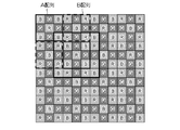
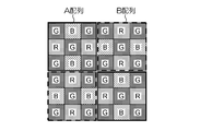
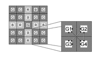
- FIG. 3A divides the basic array pattern of 6 ⁇ 6 pixels included in the color filter array of the color image sensor of the first embodiment into an A array and a B array of 3 ⁇ 3 pixels, and repeats these in the horizontal and vertical directions. It is a diagram showing a color filter array formed
- FIG. 3B is a diagram showing a characteristic arrangement of G pixels by the color filter array shown in FIG. 3A;
- FIG. 3A is a diagram showing a characteristic arrangement of G pixels by the color filter array shown in FIG. 3A
- FIG. 4 is a diagram used for explaining a pixel interpolation method at the time of synchronization processing when it is determined that there is a correlation direction in the vertical direction
- FIG. 5 is a diagram used for explaining a pixel interpolation method at the time of synchronization processing when it is determined that there is a correlation direction in the upper left diagonal direction
- FIG. 6 is a diagram showing a second embodiment of a single-plate color image sensor according to the present invention
- FIG. 7 is a diagram showing a basic array pattern included in the color filter array of the color imaging device of the second embodiment
- the basic array pattern of 6 ⁇ 6 pixels included in the color filter array of the color image sensor of the second embodiment is divided into an A array and a B array of 3 ⁇ 3 pixels, and these are repeated in the horizontal and vertical directions.
- It is a diagram showing a color filter array formed
- FIG. 9 is a diagram showing a characteristic arrangement of G pixels by the color filter array of the color image sensor of the second embodiment
- FIG. 10 is a diagram showing a third embodiment of a single-plate color image sensor according to the present invention
- FIG. 11 is a diagram showing a fourth embodiment of a single-plate color image sensor according to the present invention
- FIG. 12 is a diagram showing a fifth embodiment of a single-plate color image sensor according to the present invention.
- FIG. 13 is a diagram showing a sixth embodiment of the single-plate color image sensor according to the present invention.
- FIG. 14 is a diagram used for explaining a problem of a color imaging device having a color filter with a conventional Bayer array;
- FIG. 15 is another diagram used for explaining the problem of a color image sensor having a color filter with a conventional Bayer array.
- FIG. 1 is a diagram showing a first embodiment of a single-plate color image pickup device according to the present invention, and particularly shows a color filter array of color filters provided in the color image pickup device.
- This color image sensor is shown in FIG. 1 arranged on a light receiving surface of a plurality of pixels (not shown) composed of photoelectric conversion elements arranged in a horizontal direction and a vertical direction (two-dimensional array).
- a color filter of a color filter array is formed, and any one of the three primary color filters of red (R), green (G), and blue (B) is arranged on each pixel.
- the color image sensor is not limited to a CCD (Charge Coupled Device) color image sensor, but may be another type of image sensor such as a CMOS (Complementary Metal Oxide Semiconductor) image sensor.
- CCD Charge Coupled Device
- CMOS Complementary Metal Oxide Semiconductor
- the color filter array of the color image sensor of the first embodiment has the following features (1), (2), (3), and (4).
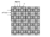
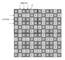
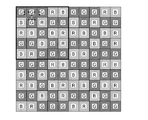
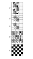
- the color filter array shown in FIG. 1 includes a basic array pattern P (pattern indicated by a thick frame) composed of a square array pattern corresponding to 6 ⁇ 6 pixels, and this basic array pattern P is repeatedly arranged in the horizontal and vertical directions. ing. That is, in this color filter array, R, G, and B color filters (R filter, G filter, and B filter) are arrayed with a predetermined periodicity.
- the R filter, the G filter, and the B filter are arranged with a predetermined periodicity in this way, a repetitive pattern is used when performing the synchronization (interpolation) processing of the R, G, and B signals read from the color image sensor. Can be processed according to
- the color filter array of the reduced image after the thinning process can be the same as the color filter array before the thinning process, and a common processing circuit is provided. Can be used.
- the basic array pattern P constituting the color filter array shown in FIG. 1 includes a G filter corresponding to a color (G color in this embodiment) that contributes most to obtain a luminance signal, and other than the G color.
- G color a color
- R filters and B filters corresponding to colors (R and B in this embodiment) are arranged in each horizontal and vertical line in the basic array pattern.
- the R, G, and B filters are respectively arranged in the horizontal and vertical lines in the basic array pattern P, the occurrence of color moire (false color) can be suppressed.
- an optical low-pass filter for suppressing the generation of false color can be prevented from being arranged in the optical path from the incident surface of the optical system to the imaging surface, or the occurrence of false color can be prevented even when the optical low-pass filter is applied. Therefore, it is possible to apply a low-frequency component for cutting high-frequency components, and not to impair the resolution.
- the G filters corresponding to the luminance system pixels are arranged in the color filter array P so as to include two or more adjacent portions in each of the horizontal, vertical, and oblique (NE, NW) directions.
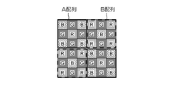
- FIG. 2 shows a state where the basic array pattern P shown in FIG. 1 is divided into 4 ⁇ 3 ⁇ 3 pixels.
- the basic array pattern P includes a 3 ⁇ 3 pixel A array surrounded by a solid frame and a 3 ⁇ 3 pixel B array surrounded by a broken frame alternately in the horizontal and vertical directions. It can also be understood that the array is arranged.
- an R filter is arranged at the center, B filters are arranged at the four corners, and G filters are arranged at the top, bottom, left and right with the center R filter interposed therebetween.
- a B filter is disposed at the center, R filters are disposed at the four corners, and G filters are disposed vertically and horizontally with the center B filter interposed therebetween.
- the color filter array of the color imaging device of the first embodiment can be regarded as the A array and the B array being alternately arranged in the horizontal and vertical directions.
- the G filter that is a luminance system pixel is arranged on the top, bottom, left and right of the 3 ⁇ 3 pixel in the A array or B array with the center filter interposed therebetween, and these 3 ⁇ 3 pixels are alternately arranged in the horizontal direction and the vertical direction.
- two or more adjacent portions of the G filter are formed in each of the horizontal, vertical, and oblique (NE, NW) directions, and are arranged in a cross shape as shown in FIG. 3B.
- the feature (2) is satisfied for the above-described features (1), (3), and the G filter.
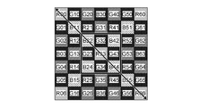
- a 5 ⁇ 5 pixel local area (area indicated by a thick frame) is extracted from the mosaic image output from the color image sensor of the first embodiment with the A array as the center.
- the eight G pixels in the local region are arranged in a cross shape as shown in FIG. 3B.
- G pixels are G1, G2, G3, G4 in order from left to right and G5, G6, G7, G8 in order from top to bottom
- the pixels G1G2, G2G3 are adjacent in the horizontal direction
- the pixels G5G6, G7G8 is adjacent in the vertical direction
- pixel G6G3 and pixel G2G7 are adjacent in the upper left diagonal direction
- pixel G6G2 and pixel G3G7 are adjacent in the upper right diagonal direction.
- the direction in which the change in luminance is the smallest (the correlation direction with the high correlation) among the horizontal, vertical, and diagonal (NE, NW) directions. ) Can be determined by the minimum pixel interval.
- correlation direction there is a correlation (correlation direction) in the direction of taking the smallest difference absolute value among these four correlation absolute values.
- the determined correlation direction can be used when performing a synchronization (interpolation) process or the like.
- the direction in which the change in luminance is the smallest is determined based on the difference value between the pixel values of adjacent G pixels.
- the direction in which the change in luminance is the smallest may be determined based on the ratio of the pixel values of the G pixels.
- the direction in which the ratio is approximately 1 is the direction in which the change in luminance is small.
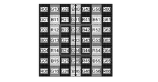
- the G pixel values G22 ′ and G24 ′ at the B22 and B24 pixel positions use the G23 pixel value, and the G pixel values G42 ′ and G44 at the B42 and B44 pixel positions.
- an average value of G32 and G34 pixel values is used as the G pixel value G33 'at the R33 pixel position.
- the R pixel value R22 ′ at the B22 pixel position uses the R21 pixel value
- the R and B pixel values R23 ′ and B23 ′ at the G23 pixel position are The average value of the pixel values of R21 and R25 and the average value of the pixel values of B22 and B24 are used, respectively.
- the R pixel values R22 ′ and R24 ′ at the pixel positions of B22 and B24 are the pixel values of R21 and R25, respectively. use.
- the R and B pixel values R32 'and B32' at the G32 pixel position use the pixel values R33 and B30, respectively.
- the B pixel value B33 'at the R33 pixel position is the average of the B30 and B36 pixel values.
- the R and B pixel values R34 'and B34' at the pixel position of G34 use the pixel values of R33 and B36, respectively.
- the R pixel value R42 ′ at the B42 pixel position uses the R41 pixel value
- the R and B pixel values R43 ′ and B43 ′ at the G43 pixel position are average values of the R41 and R45 pixel values, respectively.
- the average value of the pixel values of B42 and B44 is used, and the pixel value R44 ′ of R at the pixel position of B44 uses the pixel value of R45.
- RGB pixel values are interpolated by exchanging R and B and performing the same processing.
- RGB pixel values are interpolated by repeating the above processing every 3 ⁇ 3 pixels.
- interpolation is performed from pixels where there are pixels of the color to be interpolated in the interpolation direction.
- the R pixel value R22 ′ at the B22 pixel position uses the R23 pixel value
- the R32 pixel value R32 ′ at the G32 pixel position uses the R21 pixel value
- the B42 pixel position As the G pixel value G42 ′, the average value of the G31 and G53 pixel values is used.
- R23 ', B33', R43 ', G24', R34 ', and R44' similarly use pixel values of interpolated color pixels existing in the correlation direction.
- interpolation is performed using the color difference between G13 and the interpolated pixel value B13', and G31 and the interpolated pixel value B31 '. Specifically, the value is calculated by the following formula.
- RGB pixel values are interpolated by repeating the above processing every 3 ⁇ 3 pixels.
- the RGB pixel values can be obtained by interpolating in the same manner as in the case where the vertical direction is determined or the case where the upper left direction is determined.
- the basic array pattern P constituting the color filter array shown in FIG. 1 is point-symmetric with respect to the center of the basic array pattern P.
- the A array and the B array in the basic array pattern are point-symmetric with respect to the center R filter or G filter, respectively, and are symmetrical (line symmetric) vertically and horizontally. ing.
- the basic arrangement pattern of the color filter array shown in FIG. 1 is that the numbers of R pixels, G pixels, and B pixels corresponding to the R, G, and B filters in the basic arrangement pattern are 10 pixels, 16 pixels, and 10 pixels, respectively. It has become. That is, the ratio of the number of pixels of RGB pixels is 5: 8: 5, and the ratio of the number of G pixels that contributes most to obtain a luminance signal is the ratio of R pixels and B pixels of other colors. It is larger than the ratio of the number of pixels.
- the ratio between the number of G pixels and the number of R and B pixels is different, and in particular, the ratio of the number of G pixels that contributes most to obtain a luminance signal is equal to the number of R and B pixels. Since the ratio is larger than the ratio, aliasing at the time of the synchronization process can be suppressed and high frequency reproducibility can be improved.
- the basic array pattern P in which is point-symmetric is referred to as a basic array pattern.
- FIG. 6 is a diagram showing a second embodiment of a single-plate color image sensor according to the present invention, and particularly shows a color filter array of color filters provided in the color image sensor.
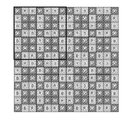
- the color filter array of the color imaging device of the second embodiment includes a basic array pattern P (pattern indicated by a thick frame) composed of a square array pattern corresponding to 6 ⁇ 6 pixels, and the basic array pattern P is in the horizontal direction. And repeatedly arranged in the vertical direction. That is, in this color filter array, R, G, and B color filters (R filter, G filter, and B filter) are arrayed with a predetermined periodicity.
- the basic arrangement pattern P that constitutes this color filter arrangement is the same as in the first embodiment, in which the filters of all the colors R, G, and B are included in each line in the horizontal and vertical directions in the basic arrangement pattern. One or more are arranged.
- the G filter corresponding to the luminance system pixel is arranged in the color filter array P so as to include two or more adjacent portions in each of the horizontal, vertical, and oblique (NE, NW) directions.
- FIG. 7 shows a state in which the basic array pattern P shown in FIG. 6 is divided into 4 ⁇ 3 ⁇ 3 pixels.
- the basic array pattern P includes a 3 ⁇ 3 pixel A array surrounded by a solid frame and a 3 ⁇ 3 pixel B array surrounded by a broken frame alternately in the horizontal and vertical directions. It can also be understood that the array is arranged.
- G filters which are luminance system pixels, are arranged at the four corners and the center, and are arranged on both diagonal lines.
- the R filter is arranged in the horizontal direction with the central G filter interposed therebetween, and the B filter is arranged in the vertical direction.
- the B filter is arranged in the horizontal direction with the central G filter interposed therebetween.
- the R filters are arranged in the vertical direction. That is, in the A array and the B array, the positional relationship between the R filter and the B filter is reversed, but the other arrangements are the same.
- the G filters at the four corners of the A array and the B array are arranged in a square array corresponding to 2 ⁇ 2 pixels by alternately arranging the A array and the B array in the horizontal and vertical directions as shown in FIG. G filter.
- the G filter which is a luminance system pixel, is arranged at the four corners and the center in the 3 ⁇ 3 pixels in the A array or the B array, and the 3 ⁇ 3 pixels are alternately arranged in the horizontal direction and the vertical direction. This is because a square array G filter corresponding to 2 ⁇ 2 pixels is formed.
- the color filter array (basic array pattern P) shown in FIG. 6 includes a square array corresponding to 2 ⁇ 2 pixels composed of G filters.
- a 5 ⁇ 5 pixel local area (area indicated by a thick frame) is extracted from the mosaic image output from the color imaging device of the second embodiment with the A array as the center.
- the G pixels of 2 ⁇ 2 pixels at the four corners in this local region are arranged as shown in FIG.
- the absolute difference values in the vertical direction of the pixel values of these G pixels Is (
- the horizontal difference absolute value is (
- the difference absolute value in the upper right diagonal direction is
- the absolute value of the difference in the upper left diagonal direction is
- the basic array pattern P constituting the color filter array shown in FIG. 6 is point-symmetric with respect to the center of the basic array pattern (the centers of the four G filters). Further, as shown in FIG. 7, the A array and the B array in the basic array pattern are also point-symmetric with respect to the central G filter, and are vertically and horizontally symmetric (line symmetric).
- the basic array pattern of the color filter array shown in FIG. 6 includes 8 pixels, 20 pixels, and R pixels corresponding to the R, G, and B filters in the basic array pattern, respectively.
- the color filter array of the color image sensor of the second embodiment has the characteristics (1), (2), (3), (4) and (4) of the color filter array of the color image sensor of the first embodiment. It has the same characteristics as 5).
- the G filter is arranged in each line in the oblique (NE, NW) direction of the color filter array, and the synchronization processing in the high frequency region is performed. It has a feature not in the color filter array of the color imaging device of the first embodiment that the reproduction accuracy can be further improved.
- FIG. 10 is a diagram showing a third embodiment of a color image sensor applied to the present invention, and particularly shows a color filter array of color filters provided in the color image sensor.
- the color filter array of this color imaging device includes a basic array pattern (pattern indicated by a thick frame) composed of a square array pattern corresponding to 4 ⁇ 4 pixels, and this basic array pattern is in the horizontal direction. And repeatedly arranged in the vertical direction. That is, in this color filter array, R, G, and B color filters (R filter, G filter, and B filter) are arrayed with a predetermined periodicity.
- one or more filters of all the colors R, G, and B are arranged in each horizontal and vertical line in the basic array pattern.
- the G filter corresponding to the luminance system pixel is arranged so that two or more adjacent portions are included in each of the horizontal, vertical, and oblique (NE, NW) directions in the basic array pattern. Based on the pixel values of the G pixels corresponding to these adjacent G filters, the luminance correlation in each of the horizontal, vertical, and oblique (NE, NW) directions can be determined with the minimum pixel interval.
- the basic array pattern constituting the color filter array is point-symmetric with respect to the center of the basic array pattern.
- the basic arrangement pattern of the color filter array shown in FIG. 10 includes 4 pixels, 8 pixels, and R pixels, G pixels, and B pixels corresponding to the R, G, and B filters in the basic arrangement pattern, respectively.
- the color filter array of the color image sensor of the third embodiment is characterized by the characteristics (1), (2), (3), (4) and (5) of the color filter array of the color image sensor 12 of the first embodiment. ).
- FIG. 11 is a diagram showing a fourth embodiment of a color image sensor applied to the present invention, and particularly shows a color filter array of color filters provided in the color image sensor.
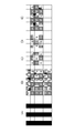
- the color filter array of this color imaging device includes a basic array pattern (pattern indicated by a thick frame) composed of a square array pattern corresponding to 5 ⁇ 5 pixels, and this basic array pattern is in the horizontal direction. And repeatedly arranged in the vertical direction. That is, in this color filter array, R, G, and B color filters (R filter, G filter, and B filter) are arrayed with a predetermined periodicity.
- one or more filters of all colors R, G, and B are arranged in each horizontal and vertical line in the basic array pattern.
- the G filter corresponding to the luminance system pixel is arranged so that two or more adjacent portions are included in each of the horizontal, vertical, and oblique (NE, NW) directions in the basic array pattern. Based on the pixel values of the G pixels corresponding to these adjacent G filters, the luminance correlation in each of the horizontal, vertical, and oblique (NE, NW) directions can be determined with the minimum pixel interval.
- the basic arrangement pattern of the color filter array shown in FIG. 11 is that the number of R pixels, G pixels, and B pixels corresponding to the R, G, and B filters in the basic arrangement pattern is 6 pixels, 13 pixels, There are 6 pixels. That is, the ratio of the number of RGB pixels is 6: 13: 6, and the ratio of the number of G pixels that contributes most to obtain a luminance signal is the ratio of the R and B pixels of other colors. It is larger than the ratio of the number of pixels.
- the color filter array of the color image sensor of the third embodiment is the same as the characteristics (1), (2), (3) and (5) of the color filter array of the color image sensor 12 of the first embodiment. have.
- FIG. 12 is a diagram showing a fifth embodiment of a color image sensor applied to the present invention, and particularly shows a color filter array of color filters provided in the color image sensor.
- the color filter array of this color imaging device includes a basic array pattern (pattern indicated by a thick frame) composed of a square array pattern corresponding to 7 ⁇ 7 pixels, and this basic array pattern is in the horizontal direction. And repeatedly arranged in the vertical direction. That is, in this color filter array, R, G, and B color filters (R filter, G filter, and B filter) are arrayed with a predetermined periodicity.
- filters of all the colors R, G, and B are arranged in the horizontal and vertical lines in the basic array pattern.
- the G filter corresponding to the luminance system pixel is arranged so that two or more adjacent portions are included in each of the horizontal, vertical, and diagonal directions (NE, NW) in the basic array pattern. That is, there are four groups of G pixels including 2 ⁇ 2 pixels adjacent vertically and horizontally in the basic array pattern. Based on the pixel values of the G pixels corresponding to these adjacent G filters, the luminance correlation in each of the horizontal, vertical, and oblique (NE, NW) directions can be determined with the minimum pixel interval.
- the basic array pattern constituting the color filter array is point-symmetric with respect to the center of the basic array pattern.
- the basic array pattern of the color filter array shown in FIG. 12 has 12 pixels, 25 pixels, and R pixels corresponding to the R, G, and B filters in the basic array pattern, respectively.
- the color filter array of the color image sensor of the fourth embodiment has the characteristics (1), (2), (3), (4) and (5) of the color filter array of the color image sensor 12 of the first embodiment. ).
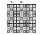
- FIG. 13 is a diagram showing a sixth embodiment of a color image sensor applied to the present invention, and particularly shows a color filter array of color filters provided in the color image sensor.
- the color filter array of this color imaging device includes a basic array pattern (pattern indicated by a thick frame) composed of a square array pattern corresponding to 8 ⁇ 8 pixels, and this basic array pattern is in the horizontal direction. And repeatedly arranged in the vertical direction. That is, in this color filter array, R, G, and B color filters (R filter, G filter, and B filter) are arrayed with a predetermined periodicity.
- filters of all the colors R, G, and B are arranged in the horizontal and vertical lines in the basic array pattern.
- the G filter corresponding to the luminance system pixel is arranged so that two or more adjacent portions are included in each of the horizontal, vertical, and diagonal directions (NE, NW) in the basic array pattern. That is, there are four groups of G pixels including 2 ⁇ 2 pixels adjacent vertically and horizontally in the basic array pattern. Based on the pixel values of the G pixels corresponding to these adjacent G filters, the luminance correlation in each of the horizontal, vertical, and oblique (NE, NW) directions can be determined with the minimum pixel interval.
- the basic array pattern constituting the color filter array is point-symmetric with respect to the center of the basic array pattern.
- the basic arrangement pattern of the color filter array shown in FIG. 13 includes 16 pixels, 32 pixels, and R pixels corresponding to the R, G, and B filters in the basic arrangement pattern, respectively. It has 16 pixels. That is, the ratio of the number of RGB pixels is 1: 2: 1, and the ratio of the number of G pixels that contributes most to obtain a luminance signal is the ratio of the R and B pixels of the other colors. It is larger than the ratio of the number of pixels.
- the color filter array of the color image sensor of the sixth embodiment has the characteristics (1), (2), (3), (4) and (5) of the color filter array of the color image sensor 12 of the first embodiment. ).
- the color imaging device having the color filters of the three primary colors of RGB has been described.
- the present invention is not limited to this, and the four colors of the three primary colors of RGB + other colors (for example, emerald (E)) are described.
- the present invention can also be applied to a color imaging device having a color filter.
- the present invention can also be applied to a color image pickup device having four color complementary color filters in which G is added to C (cyan), M (magenta), and Y (yellow) which are complementary colors of the primary colors RGB.
- the ratio of the number of G pixels that contributes most to obtain the luminance signal is higher than the ratio of the number of R and B pixels.
- the number of G pixels is preferably 1.5 or more and 3 or less of the number of R and B pixels.
Landscapes
- Engineering & Computer Science (AREA)
- Physics & Mathematics (AREA)
- Multimedia (AREA)
- Signal Processing (AREA)
- Power Engineering (AREA)
- Spectroscopy & Molecular Physics (AREA)
- Condensed Matter Physics & Semiconductors (AREA)
- General Physics & Mathematics (AREA)
- Electromagnetism (AREA)
- Computer Hardware Design (AREA)
- Microelectronics & Electronic Packaging (AREA)
- Color Television Image Signal Generators (AREA)
- Solid State Image Pick-Up Elements (AREA)
- Optical Filters (AREA)
Abstract
Description
図1は本発明に係る単板式のカラー撮像素子の第1の実施形態を示す図であり、特にカラー撮像素子に設けられているカラーフィルタのカラーフィルタ配列に関して示している。
第1の実施形態のカラー撮像素子のカラーフィルタ配列は、下記の特徴(1)、(2)、(3)、及び(4)を有している。
図1に示すカラーフィルタ配列は、6×6画素に対応する正方配列パターンからなる基本配列パターンP(太枠で示したパターン)を含み、この基本配列パターンPが水平及び垂直方向に繰り返し配置されている。即ち、このカラーフィルタ配列は、R、G、Bの各色のフィルタ(Rフィルタ、Gフィルタ、Bフィルタ)が所定の周期性をもって配列されている。
図1に示すカラーフィルタ配列を構成する基本配列パターンPは、輝度信号を得るために最も寄与する色(この実施形態では、Gの色)に対応するGフィルタと、Gの色以外の他の色(この実施形態では、R,B)に対応するRフィルタ、Bフィルタとが、基本配列パターン内の水平及び垂直方向の各ライン内に1つ以上配置されている。
輝度系画素に対応するGフィルタは、カラーフィルタ配列P内において、水平、垂直、及び斜め(NE,NW)方向の各方向に2以上隣接する部分が含まれるように配置されている。
次に、上記のようにして方向判別された相関方向を利用した補間方法について説明する。
G22’=B22+(G13+G31)/2-(B13’+B31’)/2
同様に、G32の画素位置におけるBの画素値B32’、B42の画素位置におけるRの画素値R42’の補間方法は、下式のようになる。
B32’=G32+B31’-G31
R42’=B42+R33-B33’
同様の処理を行ってB32’,G33’,B43’,R24’,B34’,G44’の補間を行う。
図1に示すカラーフィルタ配列を構成する基本配列パターンPは、その基本配列パターンPの中心に対して点対称になっている。
図1に示すカラーフィルタ配列の基本配列パターンは、その基本配列パターン内におけるR、G、Bフィルタに対応するR画素、G画素、B画素の画素数が、それぞれ10画素、16画素、10画素になっている。即ち、RGB画素の各画素数の比率は、5:8:5になっており、輝度信号を得るために最も寄与するG画素の画素数の比率は、他の色のR画素、B画素の画素数の比率よりも大きくなっている。
図6は本発明に係る単板式のカラー撮像素子の第2の実施形態を示す図であり、特にカラー撮像素子に設けられているカラーフィルタのカラーフィルタ配列に関して示している。
図10は本発明に適用されるカラー撮像素子の第3の実施形態を示す図であり、特にカラー撮像素子に設けられているカラーフィルタのカラーフィルタ配列に関して示している。
図11は本発明に適用されるカラー撮像素子の第4の実施形態を示す図であり、特にカラー撮像素子に設けられているカラーフィルタのカラーフィルタ配列に関して示している。
図12は本発明に適用されるカラー撮像素子の第5の実施形態を示す図であり、特にカラー撮像素子に設けられているカラーフィルタのカラーフィルタ配列に関して示している。
図13は本発明に適用されるカラー撮像素子の第6の実施形態を示す図であり、特にカラー撮像素子に設けられているカラーフィルタのカラーフィルタ配列に関して示している。
上記実施形態では、RGBの3原色のカラーフィルタを有するカラー撮像素子について説明したが、本発明は、これに限らず、RGBの3原色+他の色(例えば、エメラルド(E))の4色のカラーフィルタを有するカラー撮像素子にも適用できる。
Claims (11)
- 水平方向及び垂直方向に配列された光電変換素子からなる複数の画素上に、所定のカラーフィルタ配列のカラーフィルタが配設されてなる単板式のカラー撮像素子であって、
前記カラーフィルタ配列は、輝度信号を得るために最も寄与する第1の色に対応する第1のフィルタと前記第1の色以外の2色以上の第2の色に対応する第2のフィルタとが配列された所定の基本配列パターンを含み、該基本配列パターンが水平及び垂直方向に繰り返して配置され、
前記第1のフィルタ及び第2のフィルタは、それぞれ前記基本配列パターン内に前記カラーフィルタ配列の水平及び垂直方向の各ライン内に1つ以上配置され、
前記第1のフィルタは、更に前記基本配列パターン内において、水平、垂直、及び斜め(NE,NW)方向の各方向に2以上隣接する部分が含まれるように配置されているカラー撮像素子。 - 前記カラーフィルタ配列は、前記第2のフィルタのいずれか1色のフィルタを挟んで水平及び垂直方向にそれぞれ前記第1のフィルタが2以上連続配置されている請求項1に記載のカラー撮像素子。
- 前記カラーフィルタ配列は、前記第1のフィルタからなる2×2画素に対応する正方配列を含む請求項1に記載のカラー撮像素子。
- 前記所定の基本配列パターン内のカラーフィルタ配列は、該基本配列パターンの中心に対して点対称である請求項1から3のいずれか1項に記載のカラー撮像素子。
- 前記所定の基本配列パターンは、N×N(N:4以上8以下の整数)画素に対応する正方配列パターンである請求項1から4のいずれか1項に記載のカラー撮像素子。
- 前記所定の基本配列パターンは、6×6画素に対応する正方配列パターンである請求項5に記載のカラー撮像素子。
- 前記カラーフィルタ配列は、前記第1のフィルタが3×3画素群において中心のフィルタを挟んで上下左右に配置され、該3×3画素群が水平方向及び垂直方向に繰り返し配置されている請求項1から6のいずれか1項に記載のカラー撮像素子。
- 前記カラーフィルタ配列は、前記第1のフィルタが3×3画素群において中心と4隅に配置され、該3×3画素群が水平方向及び垂直方向に繰り返し配置されている請求項1から6のいずれか1項に記載のカラー撮像素子。
- 前記第1の色は、緑(G)色であり、前記第2の色は、赤(R)色及び青(B)である請求項1から8のいずれか1項に記載のカラー撮像素子。
- 前記カラーフィルタは、赤(R)、緑(G)、青(B)の色に対応するRフィルタ、Gフィルタ及びBフィルタを有し、
前記カラーフィルタ配列は、3×3画素に対応する第1の配列であって、中心にRフィルタが配置され、4隅にBフィルタが配置され、中心のRフィルタを挟んで上下左右にGフィルタが配置された第1の配列と、3×3画素に対応する第2の配列であって、中心にBフィルタが配置され、4隅にRフィルタが配置され、中心のBフィルタを挟んで上下左右にGフィルタが配置された第2の配列とが、交互に水平及び垂直方向に配列されて構成されている請求項9に記載のカラー撮像素子。 - 前記カラーフィルタは、赤(R)、緑(G)、青(B)の色に対応するRフィルタ、Gフィルタ及びBフィルタを有し、
前記カラーフィルタ配列は、3×3画素に対応する第1の配列であって、中心と4隅にGフィルタが配置され、中心のGフィルタを挟んで上下にBフィルタが配置され、左右にRフィルタが配列された第1の配列と、3×3画素に対応する第2の配列であって、中心と4隅にGフィルタが配置され、中心のGフィルタを挟んで上下にRフィルタが配置され、左右にBフィルタが配列された第2の配列とが、交互に水平方向及び垂直方向に配列されて構成されている請求項9に記載のカラー撮像素子。
Priority Applications (6)
| Application Number | Priority Date | Filing Date | Title |
|---|---|---|---|
| JP2012529061A JP5095040B1 (ja) | 2011-03-09 | 2011-07-29 | カラー撮像素子 |
| RU2013141183/07A RU2548567C1 (ru) | 2011-03-09 | 2011-07-29 | Элемент формирования цветных изображений |
| BR112012029513A BR112012029513A2 (pt) | 2011-03-09 | 2011-07-29 | elemento de imageamento de cor. |
| CN201180022122.5A CN102870405B (zh) | 2011-03-09 | 2011-07-29 | 彩色成像元件 |
| EP11860499.0A EP2685711B1 (en) | 2011-03-09 | 2011-07-29 | Color image pickup device |
| US13/661,952 US9313466B2 (en) | 2011-03-09 | 2012-10-26 | Color imaging element |
Applications Claiming Priority (4)
| Application Number | Priority Date | Filing Date | Title |
|---|---|---|---|
| JP2011051999 | 2011-03-09 | ||
| JP2011-051999 | 2011-03-09 | ||
| JP2011162416 | 2011-07-25 | ||
| JP2011-162416 | 2011-07-25 |
Related Child Applications (1)
| Application Number | Title | Priority Date | Filing Date |
|---|---|---|---|
| US13/661,952 Continuation US9313466B2 (en) | 2011-03-09 | 2012-10-26 | Color imaging element |
Publications (1)
| Publication Number | Publication Date |
|---|---|
| WO2012120705A1 true WO2012120705A1 (ja) | 2012-09-13 |
Family
ID=46797694
Family Applications (1)
| Application Number | Title | Priority Date | Filing Date |
|---|---|---|---|
| PCT/JP2011/067421 WO2012120705A1 (ja) | 2011-03-09 | 2011-07-29 | カラー撮像素子 |
Country Status (7)
| Country | Link |
|---|---|
| US (1) | US9313466B2 (ja) |
| EP (1) | EP2685711B1 (ja) |
| JP (2) | JP5095040B1 (ja) |
| CN (1) | CN102870405B (ja) |
| BR (1) | BR112012029513A2 (ja) |
| RU (1) | RU2548567C1 (ja) |
| WO (1) | WO2012120705A1 (ja) |
Cited By (1)
| Publication number | Priority date | Publication date | Assignee | Title |
|---|---|---|---|---|
| JP2013174713A (ja) * | 2012-02-24 | 2013-09-05 | Canon Inc | 光透過部材の形成方法および撮像装置の製造方法 |
Families Citing this family (11)
| Publication number | Priority date | Publication date | Assignee | Title |
|---|---|---|---|---|
| BR112012029513A2 (pt) * | 2011-03-09 | 2016-12-06 | Fujifilm Corp | elemento de imageamento de cor. |
| WO2012127701A1 (ja) * | 2011-03-24 | 2012-09-27 | 富士フイルム株式会社 | カラー撮像素子、撮像装置、及び撮像プログラム |
| JP2013201723A (ja) * | 2012-03-26 | 2013-10-03 | Hoya Corp | 撮像素子用オンチップカラーフィルタ配列 |
| CN104429061B (zh) * | 2012-07-06 | 2016-04-13 | 富士胶片株式会社 | 彩色摄像元件和摄像装置 |
| WO2014152048A2 (en) * | 2013-03-14 | 2014-09-25 | Cytonome/St, Llc | Assemblies and methods for reducing optical crosstalk in particle processing systems |
| JP2015065270A (ja) * | 2013-09-25 | 2015-04-09 | ソニー株式会社 | 固体撮像装置およびその製造方法、並びに電子機器 |
| JP2015162706A (ja) * | 2014-02-26 | 2015-09-07 | ソニー株式会社 | 画像処理装置および方法、並びにプログラム |
| USD803243S1 (en) * | 2015-04-24 | 2017-11-21 | Fujifilm Corporation | Display screen for digital camera with graphical user interface |
| EP3171406B1 (en) * | 2015-11-23 | 2019-06-19 | ams AG | Photodiode array |
| WO2020177123A1 (en) | 2019-03-07 | 2020-09-10 | Guangdong Oppo Mobile Telecommunications Corp., Ltd. | Color imaging system |
| EP4109895A4 (en) * | 2020-02-19 | 2023-07-26 | Sony Group Corporation | IMAGE PROCESSING METHOD AND SENSING DEVICE |
Citations (9)
| Publication number | Priority date | Publication date | Assignee | Title |
|---|---|---|---|---|
| JPH0823543A (ja) | 1994-07-07 | 1996-01-23 | Canon Inc | 撮像装置 |
| JPH10243407A (ja) * | 1997-02-27 | 1998-09-11 | Olympus Optical Co Ltd | 画像信号処理装置及び画像入力処理装置 |
| JPH1118097A (ja) * | 1997-06-27 | 1999-01-22 | Canon Inc | 撮像装置及び撮像方法及びその撮像方法を記録した記録媒体 |
| JP2000308080A (ja) | 1999-04-15 | 2000-11-02 | Olympus Optical Co Ltd | カラー撮像素子及びカラー撮像装置 |
| JP2000316166A (ja) * | 1999-05-06 | 2000-11-14 | Olympus Optical Co Ltd | カラー撮像素子及びカラー撮像装置 |
| JP2005136766A (ja) | 2003-10-31 | 2005-05-26 | Sony Corp | 画像処理装置および画像処理方法 |
| WO2009151903A2 (en) * | 2008-05-20 | 2009-12-17 | Pelican Imaging Corporation | Capturing and processing of images using monolithic camera array with hetergeneous imagers |
| JP2010512048A (ja) * | 2006-11-30 | 2010-04-15 | イーストマン コダック カンパニー | 低解像度画像の生成 |
| JP2010104019A (ja) | 2009-12-17 | 2010-05-06 | Mega Chips Corp | 画素補間方法 |
Family Cites Families (55)
| Publication number | Priority date | Publication date | Assignee | Title |
|---|---|---|---|---|
| JPS54102826A (en) * | 1978-01-30 | 1979-08-13 | Sony Corp | Color camera |
| US4500914A (en) * | 1981-08-01 | 1985-02-19 | Sharp Kabushiki Kaisha | Color imaging array and color imaging device |
| JP2677550B2 (ja) * | 1986-02-18 | 1997-11-17 | 株式会社東芝 | 固体撮像装置 |
| JP2739586B2 (ja) | 1989-02-10 | 1998-04-15 | 富士写真フイルム株式会社 | カラー固体撮像デバイス |
| JPH05505718A (ja) * | 1991-01-25 | 1993-08-19 | イーストマン・コダック・カンパニー | フィールドスタガ式色フィルタ図形を用いた固体カラーイメージセンサ |
| JP3268891B2 (ja) | 1992-08-14 | 2002-03-25 | オリンパス光学工業株式会社 | 内視鏡撮像装置 |
| JPH0823542A (ja) | 1994-07-11 | 1996-01-23 | Canon Inc | 撮像装置 |
| JP3551571B2 (ja) * | 1995-08-11 | 2004-08-11 | ソニー株式会社 | カラーccd固体撮像素子 |
| DE69924308T2 (de) | 1998-01-20 | 2006-03-09 | Hewlett-Packard Development Co., L.P., Houston | Farbbildaufnahmegerät |
| US6396873B1 (en) | 1999-02-25 | 2002-05-28 | Envision Advanced Medical Systems | Optical device |
| JP2000316168A (ja) * | 1999-05-06 | 2000-11-14 | Olympus Optical Co Ltd | カラー撮像素子及びカラー撮像装置 |
| JP4043197B2 (ja) | 2000-03-24 | 2008-02-06 | 三洋電機株式会社 | 単板式カラーカメラの色分離回路 |
| EP1148735A1 (en) * | 2000-04-20 | 2001-10-24 | Koninklijke Philips Electronics N.V. | Camera with color filter |
| EP1337115B1 (en) | 2000-09-07 | 2010-03-10 | Nikon Corporation | Image processor and colorimetric system converting method |
| EP2381688B1 (en) | 2001-01-09 | 2014-06-25 | Sony Corporation | Image pick up device |
| EP1395063A4 (en) | 2001-05-15 | 2008-06-04 | Matsushita Electric Ind Co Ltd | FIGURE APPARATUS AND SIGNAL PROCESSING METHOD THEREFOR |
| US7027091B1 (en) | 2001-09-17 | 2006-04-11 | Pixim, Inc. | Detection of color filter array alignment in image sensors |
| US6933971B2 (en) * | 2002-05-14 | 2005-08-23 | Kwe International, Inc. | Reconstruction of color components in digital image processing |
| JP4019417B2 (ja) | 2003-01-14 | 2007-12-12 | ソニー株式会社 | 画像処理装置および方法、記録媒体、並びにプログラム |
| JP2004266369A (ja) | 2003-02-21 | 2004-09-24 | Sony Corp | 固体撮像装置およびその駆動方法 |
| US7525584B2 (en) * | 2004-01-05 | 2009-04-28 | Lifesize Communications, Inc. | Fast edge directed demosaicing |
| US7508431B2 (en) * | 2004-06-17 | 2009-03-24 | Hoya Corporation | Solid state imaging device |
| EP1650979A1 (en) | 2004-10-21 | 2006-04-26 | STMicroelectronics S.r.l. | Method and system for demosaicing artifact removal |
| KR100723477B1 (ko) * | 2004-11-13 | 2007-05-31 | 삼성전자주식회사 | 색성분간 포화 조도의 격차를 줄이는 컬러 필터를 가지는촬영 소자 |
| JP4253634B2 (ja) | 2004-11-30 | 2009-04-15 | 富士フイルム株式会社 | デジタルカメラ |
| JP4840740B2 (ja) | 2004-12-01 | 2011-12-21 | 株式会社メガチップス | 画素補間方法および画像判定方法 |
| JP5151075B2 (ja) | 2005-06-21 | 2013-02-27 | ソニー株式会社 | 画像処理装置及び画像処理方法、撮像装置、並びにコンピュータ・プログラム |
| US8139130B2 (en) * | 2005-07-28 | 2012-03-20 | Omnivision Technologies, Inc. | Image sensor with improved light sensitivity |
| US7821553B2 (en) | 2005-12-30 | 2010-10-26 | International Business Machines Corporation | Pixel array, imaging sensor including the pixel array and digital camera including the imaging sensor |
| US7755682B2 (en) | 2006-03-29 | 2010-07-13 | Ite Tech. Inc. | Color interpolation method for Bayer filter array images |
| JP4662883B2 (ja) | 2006-05-15 | 2011-03-30 | 富士フイルム株式会社 | 二次元カラー固体撮像素子 |
| JP4983141B2 (ja) * | 2006-08-04 | 2012-07-25 | ソニー株式会社 | カラーフィルタ |
| US7701496B2 (en) | 2006-12-22 | 2010-04-20 | Xerox Corporation | Color filter pattern for color filter arrays including a demosaicking algorithm |
| JP5082528B2 (ja) | 2007-03-23 | 2012-11-28 | ソニー株式会社 | 固体撮像装置及び撮像装置 |
| JP4946581B2 (ja) | 2007-04-05 | 2012-06-06 | ソニー株式会社 | 画像処理装置 |
| US7825965B2 (en) | 2007-09-07 | 2010-11-02 | Seiko Epson Corporation | Method and apparatus for interpolating missing colors in a color filter array |
| US20090189232A1 (en) * | 2008-01-28 | 2009-07-30 | Micron Technology, Inc. | Methods and apparatuses providing color filter patterns arranged to reduce the effect of crosstalk in image signals |
| RU2383967C2 (ru) * | 2008-04-10 | 2010-03-10 | Общество с ограниченной ответственностью ООО "Юник Ай Сиз" | Фотоприемная матрица цветного изображения |
| JP4835719B2 (ja) * | 2008-05-22 | 2011-12-14 | ソニー株式会社 | 固体撮像装置及び電子機器 |
| US8164042B2 (en) * | 2008-11-06 | 2012-04-24 | Visera Technologies Company Limited | Color filter arrays and image sensors using the same |
| JP5149143B2 (ja) * | 2008-12-24 | 2013-02-20 | シャープ株式会社 | 固体撮像素子およびその製造方法、電子情報機器 |
| JP5574615B2 (ja) | 2009-04-20 | 2014-08-20 | キヤノン株式会社 | 画像処理装置、その制御方法、及びプログラム |
| US8203633B2 (en) * | 2009-05-27 | 2012-06-19 | Omnivision Technologies, Inc. | Four-channel color filter array pattern |
| US20110013056A1 (en) * | 2009-07-17 | 2011-01-20 | Searete Llc, A Limited Liability Corporation Of The State Of Delaware | Color filters and demosaicing techniques for digital imaging |
| JP5471117B2 (ja) * | 2009-07-24 | 2014-04-16 | ソニー株式会社 | 固体撮像装置とその製造方法並びにカメラ |
| JP5120441B2 (ja) | 2009-11-26 | 2013-01-16 | 株式会社ニコン | 画像処理装置 |
| JP5503522B2 (ja) * | 2010-01-20 | 2014-05-28 | キヤノン株式会社 | 撮像装置、撮像装置の制御方法 |
| JP2011171885A (ja) * | 2010-02-17 | 2011-09-01 | Renesas Electronics Corp | 画像処理装置及び画像処理方法 |
| US8692913B2 (en) * | 2010-03-16 | 2014-04-08 | Fujifilm Corporation | Solid-state electronic image sensing apparatus and method of controlling operation of same |
| JP5075934B2 (ja) * | 2010-03-25 | 2012-11-21 | 株式会社東芝 | 固体撮像装置および画像記録装置 |
| EP2680589B1 (en) * | 2011-02-21 | 2015-11-25 | FUJIFILM Corporation | Color imaging device |
| BR112012027306A2 (pt) * | 2011-02-28 | 2016-08-02 | Fujifilm Corp | aparelho de geração de imagem colorida |
| CN102959958B (zh) | 2011-02-28 | 2015-05-27 | 富士胶片株式会社 | 彩色成像设备 |
| BR112012029513A2 (pt) * | 2011-03-09 | 2016-12-06 | Fujifilm Corp | elemento de imageamento de cor. |
| JP5956782B2 (ja) * | 2011-05-26 | 2016-07-27 | キヤノン株式会社 | 撮像素子及び撮像装置 |
-
2011
- 2011-07-29 BR BR112012029513A patent/BR112012029513A2/pt not_active IP Right Cessation
- 2011-07-29 CN CN201180022122.5A patent/CN102870405B/zh active Active
- 2011-07-29 WO PCT/JP2011/067421 patent/WO2012120705A1/ja active Application Filing
- 2011-07-29 EP EP11860499.0A patent/EP2685711B1/en active Active
- 2011-07-29 JP JP2012529061A patent/JP5095040B1/ja active Active
- 2011-07-29 RU RU2013141183/07A patent/RU2548567C1/ru active
-
2012
- 2012-09-14 JP JP2012202834A patent/JP5781998B2/ja active Active
- 2012-10-26 US US13/661,952 patent/US9313466B2/en active Active
Patent Citations (9)
| Publication number | Priority date | Publication date | Assignee | Title |
|---|---|---|---|---|
| JPH0823543A (ja) | 1994-07-07 | 1996-01-23 | Canon Inc | 撮像装置 |
| JPH10243407A (ja) * | 1997-02-27 | 1998-09-11 | Olympus Optical Co Ltd | 画像信号処理装置及び画像入力処理装置 |
| JPH1118097A (ja) * | 1997-06-27 | 1999-01-22 | Canon Inc | 撮像装置及び撮像方法及びその撮像方法を記録した記録媒体 |
| JP2000308080A (ja) | 1999-04-15 | 2000-11-02 | Olympus Optical Co Ltd | カラー撮像素子及びカラー撮像装置 |
| JP2000316166A (ja) * | 1999-05-06 | 2000-11-14 | Olympus Optical Co Ltd | カラー撮像素子及びカラー撮像装置 |
| JP2005136766A (ja) | 2003-10-31 | 2005-05-26 | Sony Corp | 画像処理装置および画像処理方法 |
| JP2010512048A (ja) * | 2006-11-30 | 2010-04-15 | イーストマン コダック カンパニー | 低解像度画像の生成 |
| WO2009151903A2 (en) * | 2008-05-20 | 2009-12-17 | Pelican Imaging Corporation | Capturing and processing of images using monolithic camera array with hetergeneous imagers |
| JP2010104019A (ja) | 2009-12-17 | 2010-05-06 | Mega Chips Corp | 画素補間方法 |
Non-Patent Citations (1)
| Title |
|---|
| See also references of EP2685711A4 |
Cited By (1)
| Publication number | Priority date | Publication date | Assignee | Title |
|---|---|---|---|---|
| JP2013174713A (ja) * | 2012-02-24 | 2013-09-05 | Canon Inc | 光透過部材の形成方法および撮像装置の製造方法 |
Also Published As
| Publication number | Publication date |
|---|---|
| RU2548567C1 (ru) | 2015-04-20 |
| US9313466B2 (en) | 2016-04-12 |
| EP2685711A4 (en) | 2014-08-27 |
| CN102870405A (zh) | 2013-01-09 |
| US20130048833A1 (en) | 2013-02-28 |
| BR112012029513A2 (pt) | 2016-12-06 |
| CN102870405B (zh) | 2015-06-17 |
| RU2013141183A (ru) | 2015-04-20 |
| JP5095040B1 (ja) | 2012-12-12 |
| JP5781998B2 (ja) | 2015-09-24 |
| JP2013048428A (ja) | 2013-03-07 |
| EP2685711A1 (en) | 2014-01-15 |
| EP2685711B1 (en) | 2017-08-30 |
| JPWO2012120705A1 (ja) | 2014-07-07 |
Similar Documents
| Publication | Publication Date | Title |
|---|---|---|
| JP5095040B1 (ja) | カラー撮像素子 | |
| JP5872406B2 (ja) | カラー撮像素子 | |
| JP5872408B2 (ja) | カラー撮像装置及び画像処理方法 | |
| US20120293695A1 (en) | Color imaging apparatus | |
| US9036061B2 (en) | Color imaging apparatus | |
| US8804015B2 (en) | Color imaging device | |
| US8982253B2 (en) | Color imaging element | |
| US8743246B2 (en) | Color imaging device |
Legal Events
| Date | Code | Title | Description |
|---|---|---|---|
| WWE | Wipo information: entry into national phase |
Ref document number: 201180022122.5 Country of ref document: CN |
|
| ENP | Entry into the national phase |
Ref document number: 2012529061 Country of ref document: JP Kind code of ref document: A |
|
| 121 | Ep: the epo has been informed by wipo that ep was designated in this application |
Ref document number: 11860499 Country of ref document: EP Kind code of ref document: A1 |
|
| WWE | Wipo information: entry into national phase |
Ref document number: 9524/CHENP/2012 Country of ref document: IN |
|
| REG | Reference to national code |
Ref country code: BR Ref legal event code: B01A Ref document number: 112012029513 Country of ref document: BR |
|
| REEP | Request for entry into the european phase |
Ref document number: 2011860499 Country of ref document: EP |
|
| NENP | Non-entry into the national phase |
Ref country code: DE |
|
| ENP | Entry into the national phase |
Ref document number: 2013141183 Country of ref document: RU Kind code of ref document: A |
|
| ENP | Entry into the national phase |
Ref document number: 112012029513 Country of ref document: BR Kind code of ref document: A2 Effective date: 20121112 |