WO2012117586A1 - 海水排煙脱硫システムおよび発電システム - Google Patents
海水排煙脱硫システムおよび発電システム Download PDFInfo
- Publication number
- WO2012117586A1 WO2012117586A1 PCT/JP2011/069148 JP2011069148W WO2012117586A1 WO 2012117586 A1 WO2012117586 A1 WO 2012117586A1 JP 2011069148 W JP2011069148 W JP 2011069148W WO 2012117586 A1 WO2012117586 A1 WO 2012117586A1
- Authority
- WO
- WIPO (PCT)
- Prior art keywords
- seawater
- flue gas
- gas desulfurization
- absorption tower
- exhaust gas
- Prior art date
- Legal status (The legal status is an assumption and is not a legal conclusion. Google has not performed a legal analysis and makes no representation as to the accuracy of the status listed.)
- Ceased
Links
Images
Classifications
-
- C—CHEMISTRY; METALLURGY
- C02—TREATMENT OF WATER, WASTE WATER, SEWAGE, OR SLUDGE
- C02F—TREATMENT OF WATER, WASTE WATER, SEWAGE, OR SLUDGE
- C02F1/00—Treatment of water, waste water, or sewage
- C02F1/20—Treatment of water, waste water, or sewage by degassing, i.e. liberation of dissolved gases
-
- B—PERFORMING OPERATIONS; TRANSPORTING
- B01—PHYSICAL OR CHEMICAL PROCESSES OR APPARATUS IN GENERAL
- B01D—SEPARATION
- B01D53/00—Separation of gases or vapours; Recovering vapours of volatile solvents from gases; Chemical or biological purification of waste gases, e.g. engine exhaust gases, smoke, fumes, flue gases, aerosols
- B01D53/34—Chemical or biological purification of waste gases
- B01D53/46—Removing components of defined structure
- B01D53/48—Sulfur compounds
- B01D53/50—Sulfur oxides
- B01D53/501—Sulfur oxides by treating the gases with a solution or a suspension of an alkali or earth-alkali or ammonium compound
-
- C—CHEMISTRY; METALLURGY
- C02—TREATMENT OF WATER, WASTE WATER, SEWAGE, OR SLUDGE
- C02F—TREATMENT OF WATER, WASTE WATER, SEWAGE, OR SLUDGE
- C02F1/00—Treatment of water, waste water, or sewage
- C02F1/72—Treatment of water, waste water, or sewage by oxidation
- C02F1/74—Treatment of water, waste water, or sewage by oxidation with air
-
- F—MECHANICAL ENGINEERING; LIGHTING; HEATING; WEAPONS; BLASTING
- F01—MACHINES OR ENGINES IN GENERAL; ENGINE PLANTS IN GENERAL; STEAM ENGINES
- F01K—STEAM ENGINE PLANTS; STEAM ACCUMULATORS; ENGINE PLANTS NOT OTHERWISE PROVIDED FOR; ENGINES USING SPECIAL WORKING FLUIDS OR CYCLES
- F01K9/00—Plants characterised by condensers arranged or modified to co-operate with the engines
- F01K9/003—Plants characterised by condensers arranged or modified to co-operate with the engines condenser cooling circuits
-
- F—MECHANICAL ENGINEERING; LIGHTING; HEATING; WEAPONS; BLASTING
- F22—STEAM GENERATION
- F22B—METHODS OF STEAM GENERATION; STEAM BOILERS
- F22B1/00—Methods of steam generation characterised by form of heating method
- F22B1/02—Methods of steam generation characterised by form of heating method by exploitation of the heat content of hot heat carriers
- F22B1/18—Methods of steam generation characterised by form of heating method by exploitation of the heat content of hot heat carriers the heat carrier being a hot gas, e.g. waste gas such as exhaust gas of internal-combustion engines
-
- F—MECHANICAL ENGINEERING; LIGHTING; HEATING; WEAPONS; BLASTING
- F23—COMBUSTION APPARATUS; COMBUSTION PROCESSES
- F23J—REMOVAL OR TREATMENT OF COMBUSTION PRODUCTS OR COMBUSTION RESIDUES; FLUES
- F23J15/00—Arrangements of devices for treating smoke or fumes
- F23J15/02—Arrangements of devices for treating smoke or fumes of purifiers, e.g. for removing noxious material
- F23J15/04—Arrangements of devices for treating smoke or fumes of purifiers, e.g. for removing noxious material using washing fluids
-
- B—PERFORMING OPERATIONS; TRANSPORTING
- B01—PHYSICAL OR CHEMICAL PROCESSES OR APPARATUS IN GENERAL
- B01D—SEPARATION
- B01D2252/00—Absorbents, i.e. solvents and liquid materials for gas absorption
- B01D2252/10—Inorganic absorbents
- B01D2252/103—Water
- B01D2252/1035—Sea water
-
- C—CHEMISTRY; METALLURGY
- C02—TREATMENT OF WATER, WASTE WATER, SEWAGE, OR SLUDGE
- C02F—TREATMENT OF WATER, WASTE WATER, SEWAGE, OR SLUDGE
- C02F2103/00—Nature of the water, waste water, sewage or sludge to be treated
- C02F2103/08—Seawater, e.g. for desalination
-
- C—CHEMISTRY; METALLURGY
- C02—TREATMENT OF WATER, WASTE WATER, SEWAGE, OR SLUDGE
- C02F—TREATMENT OF WATER, WASTE WATER, SEWAGE, OR SLUDGE
- C02F2103/00—Nature of the water, waste water, sewage or sludge to be treated
- C02F2103/18—Nature of the water, waste water, sewage or sludge to be treated from the purification of gaseous effluents
-
- F—MECHANICAL ENGINEERING; LIGHTING; HEATING; WEAPONS; BLASTING
- F23—COMBUSTION APPARATUS; COMBUSTION PROCESSES
- F23J—REMOVAL OR TREATMENT OF COMBUSTION PRODUCTS OR COMBUSTION RESIDUES; FLUES
- F23J2219/00—Treatment devices
- F23J2219/40—Sorption with wet devices, e.g. scrubbers
-
- F—MECHANICAL ENGINEERING; LIGHTING; HEATING; WEAPONS; BLASTING
- F23—COMBUSTION APPARATUS; COMBUSTION PROCESSES
- F23J—REMOVAL OR TREATMENT OF COMBUSTION PRODUCTS OR COMBUSTION RESIDUES; FLUES
- F23J2900/00—Special arrangements for conducting or purifying combustion fumes; Treatment of fumes or ashes
- F23J2900/15041—Means for absorbing SOx using seawater
Definitions
- the present invention relates to a seawater flue gas desulfurization system and a power generation system that use seawater to desulfurize sulfur oxides in exhaust gas discharged from industrial combustion facilities such as coal burning, crude oil burning, and heavy oil burning.
- exhaust gas combustion exhaust gas
- SOx sulfur oxide
- SO 2 sulfur dioxide
- Seawater flue gas desulfurization equipment supplies seawater and boiler exhaust gas into a desulfurization tower (absorption tower) that has a cylindrical shape or a rectangular shape such as a substantially cylindrical shape placed vertically, and makes seawater gas-liquid contact as an absorption liquid. SOx is removed. Seawater after desulfurization (sulfur content-absorbing seawater) used as an absorbent in the desulfurization tower flows, for example, in a long water channel (Seawater Oxidation Treatment System: SOTS) with an open top and is mixed with seawater and diluted. Discharged. The sulfur-absorbing seawater is decarboxylated (explosion) by fine bubbles flowing out from an aeration apparatus installed on a part of the bottom of the water channel (see, for example, Patent Documents 1 to 3).
- SOTS Seawater Oxidation Treatment System
- the desulfurization rate of the exhaust gas obtained from the ratio of the exhaust gas supplied into the desulfurization tower and the exhaust gas discharged outside the desulfurization tower is a predetermined value (for example, , About 90%).
- the desulfurization rate of exhaust gas depends on the seawater properties such as the alkalinity of seawater, seawater temperature, seawater pH, and the concentration of sulfate ion (SO 4 2- ) contained in the desulfurized seawater. It may be higher than a predetermined value (for example, about 90%).
- an object of the present invention is to provide a seawater flue gas desulfurization system and a power generation system that can easily adjust the desulfurization rate of exhaust gas.
- the first invention of the present invention for solving the above-mentioned problems is a flue gas desulfurization absorption tower that cleans the flue gas by contacting the exhaust gas and seawater in a gas-liquid manner, and a downstream side of the flue gas desulfurization absorption tower.
- a dilution mixing tank that is provided and dilutes and mixes sulfur-absorbing seawater containing sulfur with seawater for dilution; a seawater supply line that supplies the seawater to the flue gas desulfurization absorption tower; and the flue gas desulfurization absorption tower Branches from the seawater supply line either or both inside and outside the tower, and supplies a portion of the seawater to either or both of the tower bottom of the flue gas desulfurization absorption tower and the dilution mixing tank
- a seawater flue gas desulfurization system comprising: an excess seawater branch pipe; and a control valve that adjusts an amount of excess seawater branch installed in the excess seawater branch pipe.
- a second aspect of the present invention is the seawater flue gas desulfurization system according to the first aspect, wherein the branch portion of the surplus seawater branch pipe is provided on the downstream side of the seawater feed pump provided in the seawater supply line. It is.
- the seawater is sprayed into the flue gas desulfurization absorption tower based on the desulfurization rate obtained by calculating the desulfurization rate in the flue gas desulfurization absorption tower.
- a seawater flue gas desulfurization system that calculates the amount of seawater sprayed from a spray nozzle and adjusts the amount of seawater sprayed by adjusting the opening of a control valve installed in the surplus seawater branch pipe. It is.
- a fourth aspect of the invention is the seawater flue gas desulfurization system according to any one of the first to third aspects, wherein the flue gas desulfurization absorption tower, the dilution mixing tank, and the oxidation tank are configured in the same tank. It is.
- 5th invention uses a boiler, the exhaust gas discharged
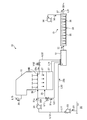
- FIG. 1 is a schematic diagram illustrating a configuration of a seawater flue gas desulfurization system according to a first embodiment of the present invention.
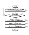
- FIG. 2 is a diagram illustrating an example of an operation method for adjusting the exhaust gas desulfurization rate.
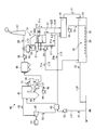
- FIG. 3 is a schematic diagram illustrating a configuration of a power generation system according to Embodiment 2 of the present invention.
- FIG. 1 is a schematic diagram showing the configuration of a seawater flue gas desulfurization system.
- the seawater flue gas desulfurization system 10 includes a flue gas desulfurization absorption tower 11, a dilution mixing tank 12, and an oxidation tank 13.
- the seawater 21 is pumped from the sea 22 to the seawater supply line L11 by the pump 23, a part of the seawater 21a is supplied to the flue gas desulfurization absorption tower 11 by the pump 24 via the seawater supply line L12, and the other remaining seawater 21b is It is supplied to the diluted mixing tank 12 through the diluted seawater supply line L13.
- seawater 21 seawater pumped directly from the sea 22 by the pump 23 is used, but the present invention is not limited to this, and the seawater 21 drained from a condenser (not shown) is used. It may be.
- the flue gas desulfurization absorption tower 11 is a tower that purifies the exhaust gas 25 by gas-liquid contact between the exhaust gas 25 and the seawater 21a.
- the seawater 21a is ejected in a liquid column shape above the spray nozzle 26, and the exhaust gas 25 and the seawater 21a supplied via the seawater supply line L12 are brought into gas-liquid contact. Desulfurization of sulfur is performed.
- the spray nozzle 26 is a spray nozzle that ejects upward in the form of a liquid column, but is not limited thereto, and may be sprayed downward in the form of a shower.
- the exhaust gas 25 and seawater 21a are brought into gas-liquid contact in the flue gas desulfurization absorption tower 11 to cause a reaction as shown in the following formula (I), and are contained in the form of SO 2 or the like in the exhaust gas 25.
- the sulfur content such as SOx is absorbed by the seawater 21a, and the sulfur content in the exhaust gas 25 is removed using the seawater 21a.
- the sulfur-absorbing seawater 27 stored at the bottom of the flue gas desulfurization absorption tower 11 is fed to the dilution mixing tank 12 via the sulfur-absorbing seawater discharge line L14.
- the sulfur-absorbing seawater 27 is mixed with the seawater 21b supplied to the dilution / mixing tank 12 and diluted.
- the purified gas 29 desulfurized by the flue gas desulfurization absorption tower 11 is released into the atmosphere through the purified gas discharge passage L15.
- the seawater supply line L12 is provided with a surplus seawater branch pipe L21, L22, or both.
- the surplus seawater branch pipe L21 is connected to the seawater supply line L12 at a branch portion 28A between the pump 24 of the seawater supply line L12 and the flue gas desulfurization absorption tower 11.
- the surplus seawater branch pipe L22 is connected to the branch portion 28B of the seawater supply line L12 in the flue gas desulfurization absorption tower 11.
- the surplus seawater 21c extracted from the surplus seawater branch pipes L21 and L22 is supplied to the dilution / mixing tank 12.
- the surplus seawater branch pipes L21 and L22 are provided with control valves V11 and V12 to adjust the amount of surplus seawater 21c extracted from the surplus seawater branch pipes L21 and L22.
- the amount of the seawater 21a supplied to the flue gas desulfurization absorption tower 11 can be easily adjusted.
- the desulfurization rate of the exhaust gas 25 in the flue gas desulfurization absorption tower 11 can be easily adjusted.
- the discharge pressure of the pump 24 is suppressed, the power for supplying the seawater 21a to the flue gas desulfurization absorption tower 11 can be reduced.
- the sulfur-absorbing seawater 27 is mixed to reduce the SO 2 concentration in the sulfur-absorbing seawater 27. Therefore, it is possible to reduce the re-scattering of SO 2 contained in the sulfur-absorbing seawater 27 in the dilution mixing tank 12 into the atmosphere.
- the desulfurization rate of the exhaust gas 25 is determined by the ratio of the inlet SO 2 concentration and the outlet SO 2 concentration in the exhaust gas 25 supplied to the flue gas desulfurization absorption tower 11 (outlet SO 2 concentration / inlet SO 2 concentration) or the sulfur content absorbing seawater 27. It adjusts with the quantity of the surplus seawater 21c extracted to the surplus seawater branch piping L21 and L22 based on the seawater property.
- the seawater property refers to the alkalinity, seawater temperature, pH, SO 4 concentration, etc. of the sulfur-absorbing seawater 27.
- Alkalinity refers to carbonate (H 2 CO 3 ), carbonate ion (CO 3 2 ⁇ ), bicarbonate ion (HCO 3 ⁇ ), OH ⁇ , organic acid or weak acid salt (silicic acid, phosphoric acid, boric acid) It is content of the component which consumes acids, such as.
- the desulfurization rate of the exhaust gas 25 is adjusted. Adjustment is made based on at least one of temperature, pH, and SO 4 concentration.
- the seawater properties are preferably adjusted based on alkalinity (HCO 3 ⁇ ).
- SO 2 concentration meters for measuring the inlet SO 2 concentration and the outlet SO 2 concentration of the exhaust gas 25 are provided at the inlet and outlet of the exhaust gas 25. Further, the flue gas desulfurization absorption tower 11 is provided with a thermometer, a pH measuring device, and an SO 4 concentration meter for measuring the seawater temperature, pH, and SO 4 concentration of the sulfur-absorbing seawater 27.
- FIG. 2 is a diagram illustrating an example of an operation method for adjusting the desulfurization rate of the exhaust gas 25.
- the desulfurization rate of the exhaust gas 25 and the seawater properties of the sulfur-absorbing seawater 27 in the flue gas desulfurization absorption tower 11 are obtained (step S11). It is determined whether or not the desulfurization rate of the exhaust gas 25 is equal to or greater than a predetermined threshold (for example, a set value + ⁇ ) (step S12).
- the predetermined threshold value of the desulfurization rate is, for example, a predetermined set value (for example, the desulfurization rate is 90%) that the flue gas desulfurization absorption tower 11 normally requires for desulfurization.
- the sum of ⁇ and (for example, the desulfurization rate is several percent).
- the spray amount necessary for spraying the seawater 21a is calculated from the seawater properties of the sulfur-absorbing seawater 27 and the desulfurization rate of the exhaust gas 25. (Step S13).
- the opening degree of the control valves V11 and V12 is calculated based on the spray amount necessary for spraying the seawater 21a (step S14). Based on the calculated opening of the control valves V11, V12, the degree of opening / closing of the control valves V11, V12 is adjusted (step S15).
- the amount of seawater 21a supplied to the flue gas desulfurization absorption tower 11 can be adjusted by adjusting the degree of opening and closing of the control valves V11 and V12 based on the calculated opening of the control valves V11 and V12,
- the spray amount of the seawater 21a sprayed from the spray nozzle 26 can be easily adjusted. Thereby, as above-mentioned, in the flue gas desulfurization absorption tower 11, adjustment of the desulfurization rate of the waste gas 25 can be performed easily.
- the surplus seawater branch pipes L21 and L22 are connected to the dilution / mixing tank 12, and the surplus seawater 21c extracted from the surplus seawater branch pipes L21 and L22 is supplied to the dilution / mixing tank 12.
- the supply destination of the extracted surplus seawater 21c is not limited to the dilution mixing tank 12, but may be supplied to the bottom of the flue gas desulfurization absorption tower 11, or may be an oxidation tank You may make it send to 13 directly.
- the extracted surplus seawater 21c may be supplied to both the dilution mixing tank 12 and the tower bottom of the flue gas desulfurization absorption tower 11, or the oxidation tank 13 and the flue gas desulfurization absorption tower 11 may be supplied. You may make it send to both a tower bottom part.
- the extracted surplus seawater 21c may be supplied to the dilution mixing tank 12, the oxidation tank 13, and the tower bottoms of the flue gas desulfurization absorption tower 11.
- the dilution mixing tank 12 is a tank that is provided on the downstream side of the flue gas desulfurization absorption tower 11 and dilutes and mixes the sulfur-absorbing seawater 27 containing sulfur with the seawater 21b for dilution.
- the sulfur-absorbing seawater 27 containing the sulfur content generated by bringing the sulfur content in the exhaust gas 25 into contact with the seawater 21a and desulfurizing the seawater in the flue gas desulfurization absorption tower 11 is mixed and diluted with the seawater 21b. To do.
- the pH of the sulfur-absorbing diluted seawater 31 in the dilution mixing tank 12 can be raised, and re-emission of SO 2 gas can be prevented. Further, by preventing SO 2 from being diffused and leaking outside in the dilution / mixing tank 12, it is possible to prevent emission of an irritating odor.
- the sulfur content absorption diluted seawater 31 is fed to the oxidation tank 13 provided on the downstream side of the dilution mixing tank 12.
- the oxidation tank 13 is a tank that is provided on the downstream side of the dilution mixing tank 12 and has an aeration apparatus (aeration apparatus) 32 that performs water quality recovery processing of the sulfur content absorption diluted seawater 31.
- the aeration apparatus 32 includes an oxidizing air blower 34 that supplies air 33, an air diffuser 35 that supplies the air 33, and an oxidizing air nozzle 36 that supplies the air 33 to the sulfur content absorption diluted seawater 31 in the oxidation tank 13. It has.
- the external air 33 is sent from the oxidizing air nozzle 36 into the oxidation tank 13 through the air diffusion pipe 35 by the oxidizing air blower 34, and the oxygen is dissolved as shown in the following formula (II).
- the sulfur content in the sulfur content absorption diluted seawater 31 comes into contact with the air 33, and the oxidation reaction of bisulfite ions (HSO 3 ⁇ ) as shown in the following formulas (III) to (V) and the bicarbonate ions ( HCO 3 ⁇ ) decarboxylation reaction occurs, and the sulfur content absorption diluted seawater 31 is recovered in water quality to become water quality recovered seawater 37.
- bisulfite ions HSO 3 ⁇
- HCO 3 ⁇ bicarbonate ions
- the seawater flue gas desulfurization system 10 is configured such that the ratio of the inlet SO 2 concentration and the outlet SO 2 concentration of the exhaust gas 25 supplied to the flue gas desulfurization absorption tower 11 and the alkali of the sulfur content absorption seawater 27.
- the amount of surplus seawater 21c extracted to the surplus seawater branch pipes L21 and L22 based on the degree, the amount of seawater 21a sprayed from the spray nozzle 26 is adjusted to adjust the desulfurization rate of the exhaust gas 25. It can be done easily.
- the motive power which supplies the seawater 21a to the flue gas desulfurization absorption tower 11 can be reduced.
- seawater flue gas desulfurization system 10 it is possible to provide a seawater flue gas desulfurization device with high safety and reliability while maintaining a stable desulfurization rate of the exhaust gas 25.
- seawater flue gas desulfurization system for treating the seawater 21a used for the seawater desulfurization in the flue gas desulfurization absorption tower 11 has been described, but the present invention is not limited to this.
- Seawater flue gas desulfurization equipment is included in exhaust gas discharged from factories in various industries, power plants such as large and medium-sized thermal power plants, large boilers for electric utilities or general industrial boilers, steelworks, smelters, etc.
- the present invention can also be applied to a seawater flue gas desulfurization apparatus that desulfurizes sulfur oxides.
- the flue gas desulfurization absorption tower 11, the dilution mixing tank 12 and the oxidation tank 13 are independent as separate tanks, and the flue gas desulfurization absorption tower 11, the dilution mixing tank 12, the oxidation tank 13, and the like.
- the present embodiment is not limited to this, and the flue gas desulfurization absorption tower 11, the dilution mixing tank 12, and the oxidation tank 13 may be integrated into a single tank.
- the dilution mixing tank 12 and the oxidation tank 13 may be integrated into a single tank.
- a power generation system according to Example 2 of the present invention will be described with reference to the drawings.
- the seawater flue gas desulfurization system according to the first embodiment is used for the seawater flue gas desulfurization system applied to the power generation system according to the present embodiment.
- symbol is attached
- FIG. 3 is a schematic diagram illustrating a configuration of a power generation system according to Embodiment 2 of the present invention.
- a power generation system 40 according to this embodiment includes a boiler 41, a steam turbine 42, a condenser 43, a flue gas denitration device 44, a dust collector 45, and a seawater flue gas desulfurization system. 10.
- the sulfur-absorbing seawater 27 means used seawater that has absorbed sulfur such as SO 2 in the seawater flue gas desulfurization system 10.
- the boiler 41 injects and burns fuel 46 supplied from an oil tank or a coal mill from a burner (not shown) together with air 48 preheated by an air preheater (AH) 47.
- the air 48 supplied from the outside is supplied to the air preheater 47 by the pushing fan 49 and preheated.
- the fuel 46 and the air 48 preheated by the air preheater 47 are supplied to the burner, and the fuel 46 is burned by the boiler 41. Thereby, the steam 50 for driving the steam turbine 42 is generated.
- the exhaust gas 51 generated by combustion in the boiler 41 is sent to the flue gas denitration device 44. Further, the exhaust gas 51 is used as a heat source for exchanging heat with the water 52 discharged from the condenser 43 and generating steam 50.
- the steam turbine 42 uses this steam 50 to drive the generator 53.
- the condenser 43 collects the water 52 condensed by the steam turbine 42 and returns it to the boiler 41 for circulation.
- the exhaust gas 51 discharged from the boiler 41 is denitrated in the flue gas denitration device 44, exchanged heat with the air 48 by the air preheater 47, and then sent to the dust collector 45 to remove the dust in the exhaust gas 51.
- the exhaust gas 51 removed by the dust collector 45 is supplied into the seawater flue gas desulfurization system 10 by the induction fan 55.
- the exhaust gas 51 is heat-exchanged by the heat exchanger 56 with the purified gas 29 desulfurized and discharged by the seawater flue gas desulfurization system 10 and then supplied into the seawater flue gas desulfurization system 10.
- the exhaust gas 51 may be directly supplied to the seawater flue gas desulfurization system 10 without exchanging heat with the purified gas 29 by the heat exchanger 56.
- the heat exchanger 56 includes a heat recovery device and a reheater, and a heat medium circulates between the heat recovery device and the reheater.
- the heat recovery unit is provided between the air preheater 47 and the dust collector 45 and exchanges heat between the exhaust gas 51 discharged from the boiler 41 and the heat medium.
- the reheater is provided on the downstream side of the flue gas desulfurization absorption tower 11, and exchanges heat between the purified gas 57 discharged from the flue gas desulfurization absorption tower 11 and the heat medium to reheat the purified gas 29. To do.
- the seawater flue gas desulfurization system 10 is the seawater flue gas desulfurization apparatus according to Example 1 described above. That is, the seawater flue gas desulfurization system 10 includes the flue gas desulfurization absorption tower 11, the dilution mixing tank 12, the oxidation tank 13, and the surplus seawater branch pipes L21 and L22.
- seawater desulfurization is performed using the seawater 21 pumped up from the sea 22 by the sulfur content contained in the exhaust gas 51. Further, the seawater 21 is pumped from the sea 22 by the pump 23 and heat exchange is performed by the condenser 43, and then a part of the seawater 21a is sent to the seawater flue gas desulfurization system 10 by the pump 24 via the seawater supply line L12. The The remaining seawater 21b is fed to the upstream side of the dilution / mixing tank 12 via the seawater supply line L13.
- the exhaust gas 51 and the seawater 21a are brought into gas-liquid contact, and the sulfur content in the exhaust gas 51 is absorbed by the seawater 21a.
- the sulfur-absorbing seawater 27 that has absorbed the sulfur is fed from the flue gas desulfurization absorption tower 11 to the upstream side of the dilution mixing tank 12, mixed with the seawater 21b, and diluted.
- the exhaust gas 51 purified by the seawater flue gas desulfurization system 10 becomes the purified gas 29 and is discharged from the chimney 57 through the purified gas discharge passage L15.
- the seawater flue gas desulfurization system 10 is provided with surplus seawater branch pipes L21 and L22 in the seawater supply line L12.
- the surplus seawater branch pipe L21 is connected to the seawater supply line L12 between the pump 24 of the seawater supply line L12 and the flue gas desulfurization absorption tower 11.
- the surplus seawater branch pipe L22 is connected to the seawater supply line L12 in the flue gas desulfurization absorption tower 11.
- the surplus seawater 21c extracted from the surplus seawater branch pipes L21 and L22 is supplied to the dilution / mixing tank 12.
- the desulfurization rate of the exhaust gas 51 is adjusted.
- the desulfurization rate of the exhaust gas 25 is determined by the ratio of the inlet SO 2 concentration and the outlet SO 2 concentration in the exhaust gas 51 supplied to the flue gas desulfurization absorption tower 11 (outlet SO 2 concentration / inlet SO 2 concentration) and sulfur.
- the seawater 21 pumped from the sea 22 is heat-exchanged by the condenser 43 and then sent to the seawater flue gas desulfurization system 10 for use in seawater desulfurization.
- the seawater 21 pumped from the sea 22 is condensed into water. Instead of heat exchange in the vessel 43, it may be directly fed to the seawater flue gas desulfurization system 10 and used for seawater desulfurization.
- the sulfur-absorbing seawater 27 is mixed with the seawater 21b in the dilution / mixing tank 12, and the diluted sulfur-absorbing / diluting seawater 31 is supplied to the oxidation tank 13 to recover the water content of the sulfur-absorbing diluted seawater 31 in the oxidation tank 13.
- Water quality recovery seawater 37 The water quality recovery seawater 37 obtained in the oxidation tank 13 is discharged from the oxidation tank 13 to the sea 22 via the seawater discharge line L32 with pH, dissolved oxygen concentration, and COD at a level at which seawater can be discharged.
- a part of the seawater 21 may be supplied from the seawater supply line L11 to the downstream side of the water quality recovery seawater 37 in the oxidation tank 13 via the diluted seawater supply line L13.
- the water quality recovery seawater 37 can be further diluted.
- the pH of the water quality recovery seawater 37 is increased, the pH of the seawater drainage liquid is increased to near the seawater, the drainage standard for the pH of the seawater drainage liquid (pH 6.0 or higher) is satisfied, and COD is reduced. It is possible to release the pH and COD of the water quality recovery seawater 37 as a level at which seawater can be discharged.
- the power generation system 40 it is possible to easily adjust the desulfurization rate of the exhaust gas 51 in the flue gas desulfurization absorption tower 11, and supply the seawater 21a to the flue gas desulfurization absorption tower 11.
- the driving power can be reduced and the running cost can be suppressed.
- excess seawater 21c withdrawn in excess seawater branch pipe L21, L22 is supplied to the dilution mixing tank 12, since it is possible to reduce the SO 2 concentration of sulfur in the absorbing seawater 27, sulfur in the dilution mixing tank 12 It is possible to reduce the re-scattering of SO 2 contained in the partial absorption seawater 27 into the atmosphere. Therefore, it is possible to provide a power generation system with high safety and reliability while maintaining a stable desulfurization rate of the exhaust gas 51.
- seawater flue gas desulfurization apparatus 10 is included in exhaust gas discharged from factories in various industries, power plants such as large and medium-sized thermal power plants, large boilers for electric utilities, or general industrial boilers. It can be used for removal of sulfur content in the sulfur content absorption solution produced by desulfurizing the sulfur oxide.
Landscapes
- Engineering & Computer Science (AREA)
- Chemical & Material Sciences (AREA)
- Life Sciences & Earth Sciences (AREA)
- Environmental & Geological Engineering (AREA)
- Mechanical Engineering (AREA)
- General Engineering & Computer Science (AREA)
- Hydrology & Water Resources (AREA)
- Combustion & Propulsion (AREA)
- Organic Chemistry (AREA)
- Water Supply & Treatment (AREA)
- Physics & Mathematics (AREA)
- General Chemical & Material Sciences (AREA)
- Sustainable Energy (AREA)
- Sustainable Development (AREA)
- Health & Medical Sciences (AREA)
- Biomedical Technology (AREA)
- Analytical Chemistry (AREA)
- Thermal Sciences (AREA)
- Oil, Petroleum & Natural Gas (AREA)
- Chemical Kinetics & Catalysis (AREA)
- Treating Waste Gases (AREA)
- Chimneys And Flues (AREA)
- Gas Separation By Absorption (AREA)
- Engine Equipment That Uses Special Cycles (AREA)
Priority Applications (1)
| Application Number | Priority Date | Filing Date | Title |
|---|---|---|---|
| CN201180061109.0A CN103282101B (zh) | 2011-02-28 | 2011-08-25 | 海水排烟脱硫系统及发电系统 |
Applications Claiming Priority (2)
| Application Number | Priority Date | Filing Date | Title |
|---|---|---|---|
| JP2011042962A JP5773687B2 (ja) | 2011-02-28 | 2011-02-28 | 海水排煙脱硫システムおよび発電システム |
| JP2011-042962 | 2011-02-28 |
Publications (1)
| Publication Number | Publication Date |
|---|---|
| WO2012117586A1 true WO2012117586A1 (ja) | 2012-09-07 |
Family
ID=46757540
Family Applications (1)
| Application Number | Title | Priority Date | Filing Date |
|---|---|---|---|
| PCT/JP2011/069148 Ceased WO2012117586A1 (ja) | 2011-02-28 | 2011-08-25 | 海水排煙脱硫システムおよび発電システム |
Country Status (5)
| Country | Link |
|---|---|
| JP (1) | JP5773687B2 (enExample) |
| CN (1) | CN103282101B (enExample) |
| CL (1) | CL2013001879A1 (enExample) |
| TW (1) | TWI482657B (enExample) |
| WO (1) | WO2012117586A1 (enExample) |
Cited By (3)
| Publication number | Priority date | Publication date | Assignee | Title |
|---|---|---|---|---|
| CN104736225A (zh) * | 2013-01-29 | 2015-06-24 | 富士电机株式会社 | 气体洗涤器的海水量控制装置、气体洗涤器的海水量控制方法、碱量控制装置及碱量控制方法 |
| CN105899281A (zh) * | 2014-07-18 | 2016-08-24 | 富士电机株式会社 | 洗涤器的海水量控制装置、洗涤器的海水量控制方法及碱量控制装置 |
| CN113740197A (zh) * | 2021-06-29 | 2021-12-03 | 西安热工研究院有限公司 | 一种烟气海水脱硫装置的除雾器性能评估系统及方法 |
Families Citing this family (12)
| Publication number | Priority date | Publication date | Assignee | Title |
|---|---|---|---|---|
| EP2937131B1 (en) | 2012-12-19 | 2018-04-04 | Fuji Electric Co., Ltd. | Exhaust gas purifying apparatus |
| JP2014233702A (ja) * | 2013-06-04 | 2014-12-15 | 三菱重工業株式会社 | 海水脱硫装置及び海水脱硫システム |
| JP6302191B2 (ja) * | 2013-09-02 | 2018-03-28 | 三菱日立パワーシステムズ株式会社 | 発電システム |
| CN104162361A (zh) * | 2014-07-29 | 2014-11-26 | 江苏南极机械有限责任公司 | 一种利用海水吸收净化柴油机尾气中so2的装置及吸收方法 |
| EP3189883B1 (en) | 2014-09-02 | 2019-09-04 | Fuji Electric Co., Ltd. | Exhaust gas treatment device and waste water treatment method for exhaust gas treatment device |
| JP6632452B2 (ja) * | 2016-03-31 | 2020-01-22 | 三菱日立パワーシステムズ株式会社 | 充填塔用の充填物及び海水脱硫装置 |
| CN106076066A (zh) * | 2016-06-11 | 2016-11-09 | 彭斯干 | 海水式碳捕集封存方法及装置 |
| CN109843714B (zh) * | 2017-03-24 | 2021-09-24 | 三菱造船株式会社 | 船舶用脱硫装置的排水系统 |
| SG10202003942VA (en) * | 2017-03-28 | 2020-05-28 | Mitsubishi Hitachi Power Sys | Ship desulfurization device, hull integrated desulfurization device, ship, and method for assembling hull integrated desulfurization device to ship |
| KR101918663B1 (ko) | 2018-04-18 | 2018-11-14 | 주식회사 지스코 | 발전시스템 |
| CN112452126B (zh) * | 2020-11-25 | 2025-01-21 | 南通电力设计院有限公司 | 一种用于火力发电的气体脱硫处理系统 |
| CN113198294B (zh) * | 2021-05-21 | 2021-11-19 | 华能国际电力股份有限公司大连电厂 | 一种海水脱硫控制方法和设备 |
Citations (5)
| Publication number | Priority date | Publication date | Assignee | Title |
|---|---|---|---|---|
| JPH11244646A (ja) * | 1998-03-05 | 1999-09-14 | Ishikawajima Harima Heavy Ind Co Ltd | 排煙脱硫装置の吸収剤スラリー流量制御方法及び装置 |
| JP2005066505A (ja) * | 2003-08-26 | 2005-03-17 | Mitsubishi Heavy Ind Ltd | 排ガス処理装置および処理方法 |
| JP2008207149A (ja) * | 2007-02-28 | 2008-09-11 | Mitsubishi Heavy Ind Ltd | 海水排煙脱硫システム |
| JP2010125377A (ja) * | 2008-11-27 | 2010-06-10 | Babcock Hitachi Kk | 湿式脱硫装置 |
| US20100206171A1 (en) * | 2008-06-13 | 2010-08-19 | Sigan Peng | Ship flue gas desulphurization method and equipment |
-
2011
- 2011-02-28 JP JP2011042962A patent/JP5773687B2/ja not_active Expired - Fee Related
- 2011-08-25 CN CN201180061109.0A patent/CN103282101B/zh not_active Expired - Fee Related
- 2011-08-25 WO PCT/JP2011/069148 patent/WO2012117586A1/ja not_active Ceased
- 2011-11-28 TW TW100143573A patent/TWI482657B/zh not_active IP Right Cessation
-
2013
- 2013-06-25 CL CL2013001879A patent/CL2013001879A1/es unknown
Patent Citations (5)
| Publication number | Priority date | Publication date | Assignee | Title |
|---|---|---|---|---|
| JPH11244646A (ja) * | 1998-03-05 | 1999-09-14 | Ishikawajima Harima Heavy Ind Co Ltd | 排煙脱硫装置の吸収剤スラリー流量制御方法及び装置 |
| JP2005066505A (ja) * | 2003-08-26 | 2005-03-17 | Mitsubishi Heavy Ind Ltd | 排ガス処理装置および処理方法 |
| JP2008207149A (ja) * | 2007-02-28 | 2008-09-11 | Mitsubishi Heavy Ind Ltd | 海水排煙脱硫システム |
| US20100206171A1 (en) * | 2008-06-13 | 2010-08-19 | Sigan Peng | Ship flue gas desulphurization method and equipment |
| JP2010125377A (ja) * | 2008-11-27 | 2010-06-10 | Babcock Hitachi Kk | 湿式脱硫装置 |
Cited By (7)
| Publication number | Priority date | Publication date | Assignee | Title |
|---|---|---|---|---|
| CN104736225A (zh) * | 2013-01-29 | 2015-06-24 | 富士电机株式会社 | 气体洗涤器的海水量控制装置、气体洗涤器的海水量控制方法、碱量控制装置及碱量控制方法 |
| CN104736225B (zh) * | 2013-01-29 | 2018-05-04 | 富士电机株式会社 | 气体洗涤器的海水量控制装置、气体洗涤器的海水量控制方法、碱量控制装置及碱量控制方法 |
| US10150078B2 (en) | 2013-01-29 | 2018-12-11 | Fuji Electric Co., Ltd. | Amount of seawater control device for scrubber, amount of seawater control method for scrubber, and amount of alkali control device and amount of alkali control method |
| CN105899281A (zh) * | 2014-07-18 | 2016-08-24 | 富士电机株式会社 | 洗涤器的海水量控制装置、洗涤器的海水量控制方法及碱量控制装置 |
| US10099175B2 (en) | 2014-07-18 | 2018-10-16 | Fuji Electric Co., Ltd. | Amount-of-seawater control device for scrubber, amount-of-seawater control method for scrubber, and amount-of-alkali control device |
| CN105899281B (zh) * | 2014-07-18 | 2018-12-14 | 富士电机株式会社 | 洗涤器的海水量控制装置、洗涤器的海水量控制方法及碱量控制装置 |
| CN113740197A (zh) * | 2021-06-29 | 2021-12-03 | 西安热工研究院有限公司 | 一种烟气海水脱硫装置的除雾器性能评估系统及方法 |
Also Published As
| Publication number | Publication date |
|---|---|
| TWI482657B (zh) | 2015-05-01 |
| JP2012179521A (ja) | 2012-09-20 |
| CN103282101A (zh) | 2013-09-04 |
| CN103282101B (zh) | 2015-06-03 |
| JP5773687B2 (ja) | 2015-09-02 |
| CL2013001879A1 (es) | 2013-11-29 |
| TW201238644A (en) | 2012-10-01 |
Similar Documents
| Publication | Publication Date | Title |
|---|---|---|
| JP5773687B2 (ja) | 海水排煙脱硫システムおよび発電システム | |
| JP2012179521A5 (enExample) | ||
| CN204073811U (zh) | 海水排烟脱硫系统及发电系统 | |
| CN101063527B (zh) | 控制烟道气中水分浓度的方法 | |
| CN102343206B (zh) | 排气的处理方法以及设备 | |
| JPWO2010116482A1 (ja) | 海水脱硫酸化処理装置、脱硫海水の処理方法及びこれを適用した発電システム | |
| KR20150123329A (ko) | 배기 가스 중의 SOx의 감소를 위한 정화 시스템 및 방법 | |
| CN204107298U (zh) | 氧化槽、海水排烟脱硫系统及发电系统 | |
| JP4959303B2 (ja) | 排気ガスの処理方法及び処理装置 | |
| JP2012239958A (ja) | 湿式排煙脱硫装置と方法 | |
| JP2013244454A (ja) | 排ガス処理装置 | |
| JP2012050931A (ja) | 排煙処理装置及び排煙処理方法 | |
| JP2015142912A (ja) | 亜硫酸ガス含有排ガスの脱硫方法および脱硫装置 | |
| JP5106479B2 (ja) | 脱硫装置における水銀再放出抑制方法および装置 | |
| JP2011230047A (ja) | 排煙脱硫装置及びこれを備えた酸素燃焼装置と方法 | |
| WO2013118683A1 (ja) | 脱硫海水処理システム | |
| JP2009172541A (ja) | 湿式排煙脱硫装置の酸化用空気供給量制御方法 | |
| KR102814225B1 (ko) | 수소 및 암모니아 제조 시스템 | |
| WO2010131327A1 (ja) | 海水排煙脱硫装置及び脱硫海水の処理方法 | |
| JP5991664B2 (ja) | 排煙脱硫システム | |
| CN102343209B (zh) | 应用锅炉排污水的烟气海水脱硫系统 | |
| JP2013034965A (ja) | 湿式排煙処理装置と方法 | |
| JP5039719B2 (ja) | 高湿分利用ガスタービンシステム及びガスタービンシステムの回収水脱気方法 | |
| KR20180079756A (ko) | 해수담수화 설비의 해수농축수를 이용한 해수탈황설비의 구성 및 처리방법 | |
| JP2009095696A (ja) | 排ガス脱硫装置酸化塔のバイパス運転方法 |
Legal Events
| Date | Code | Title | Description |
|---|---|---|---|
| 121 | Ep: the epo has been informed by wipo that ep was designated in this application |
Ref document number: 11859882 Country of ref document: EP Kind code of ref document: A1 |
|
| WWE | Wipo information: entry into national phase |
Ref document number: 2013001879 Country of ref document: CL |
|
| NENP | Non-entry into the national phase |
Ref country code: DE |
|
| 122 | Ep: pct application non-entry in european phase |
Ref document number: 11859882 Country of ref document: EP Kind code of ref document: A1 |