WO2012117586A1 - 海水排煙脱硫システムおよび発電システム - Google Patents
海水排煙脱硫システムおよび発電システム Download PDFInfo
- Publication number
- WO2012117586A1 WO2012117586A1 PCT/JP2011/069148 JP2011069148W WO2012117586A1 WO 2012117586 A1 WO2012117586 A1 WO 2012117586A1 JP 2011069148 W JP2011069148 W JP 2011069148W WO 2012117586 A1 WO2012117586 A1 WO 2012117586A1
- Authority
- WO
- WIPO (PCT)
- Prior art keywords
- seawater
- flue gas
- gas desulfurization
- absorption tower
- exhaust gas
- Prior art date
Links
Images
Classifications
-
- C—CHEMISTRY; METALLURGY
- C02—TREATMENT OF WATER, WASTE WATER, SEWAGE, OR SLUDGE
- C02F—TREATMENT OF WATER, WASTE WATER, SEWAGE, OR SLUDGE
- C02F1/00—Treatment of water, waste water, or sewage
- C02F1/20—Treatment of water, waste water, or sewage by degassing, i.e. liberation of dissolved gases
-
- B—PERFORMING OPERATIONS; TRANSPORTING
- B01—PHYSICAL OR CHEMICAL PROCESSES OR APPARATUS IN GENERAL
- B01D—SEPARATION
- B01D53/00—Separation of gases or vapours; Recovering vapours of volatile solvents from gases; Chemical or biological purification of waste gases, e.g. engine exhaust gases, smoke, fumes, flue gases, aerosols
- B01D53/34—Chemical or biological purification of waste gases
- B01D53/46—Removing components of defined structure
- B01D53/48—Sulfur compounds
- B01D53/50—Sulfur oxides
- B01D53/501—Sulfur oxides by treating the gases with a solution or a suspension of an alkali or earth-alkali or ammonium compound
-
- C—CHEMISTRY; METALLURGY
- C02—TREATMENT OF WATER, WASTE WATER, SEWAGE, OR SLUDGE
- C02F—TREATMENT OF WATER, WASTE WATER, SEWAGE, OR SLUDGE
- C02F1/00—Treatment of water, waste water, or sewage
- C02F1/72—Treatment of water, waste water, or sewage by oxidation
- C02F1/74—Treatment of water, waste water, or sewage by oxidation with air
-
- F—MECHANICAL ENGINEERING; LIGHTING; HEATING; WEAPONS; BLASTING
- F01—MACHINES OR ENGINES IN GENERAL; ENGINE PLANTS IN GENERAL; STEAM ENGINES
- F01K—STEAM ENGINE PLANTS; STEAM ACCUMULATORS; ENGINE PLANTS NOT OTHERWISE PROVIDED FOR; ENGINES USING SPECIAL WORKING FLUIDS OR CYCLES
- F01K9/00—Plants characterised by condensers arranged or modified to co-operate with the engines
- F01K9/003—Plants characterised by condensers arranged or modified to co-operate with the engines condenser cooling circuits
-
- F—MECHANICAL ENGINEERING; LIGHTING; HEATING; WEAPONS; BLASTING
- F22—STEAM GENERATION
- F22B—METHODS OF STEAM GENERATION; STEAM BOILERS
- F22B1/00—Methods of steam generation characterised by form of heating method
- F22B1/02—Methods of steam generation characterised by form of heating method by exploitation of the heat content of hot heat carriers
- F22B1/18—Methods of steam generation characterised by form of heating method by exploitation of the heat content of hot heat carriers the heat carrier being a hot gas, e.g. waste gas such as exhaust gas of internal-combustion engines
-
- F—MECHANICAL ENGINEERING; LIGHTING; HEATING; WEAPONS; BLASTING
- F23—COMBUSTION APPARATUS; COMBUSTION PROCESSES
- F23J—REMOVAL OR TREATMENT OF COMBUSTION PRODUCTS OR COMBUSTION RESIDUES; FLUES
- F23J15/00—Arrangements of devices for treating smoke or fumes
- F23J15/02—Arrangements of devices for treating smoke or fumes of purifiers, e.g. for removing noxious material
- F23J15/04—Arrangements of devices for treating smoke or fumes of purifiers, e.g. for removing noxious material using washing fluids
-
- B—PERFORMING OPERATIONS; TRANSPORTING
- B01—PHYSICAL OR CHEMICAL PROCESSES OR APPARATUS IN GENERAL
- B01D—SEPARATION
- B01D2252/00—Absorbents, i.e. solvents and liquid materials for gas absorption
- B01D2252/10—Inorganic absorbents
- B01D2252/103—Water
- B01D2252/1035—Sea water
-
- C—CHEMISTRY; METALLURGY
- C02—TREATMENT OF WATER, WASTE WATER, SEWAGE, OR SLUDGE
- C02F—TREATMENT OF WATER, WASTE WATER, SEWAGE, OR SLUDGE
- C02F2103/00—Nature of the water, waste water, sewage or sludge to be treated
- C02F2103/08—Seawater, e.g. for desalination
-
- C—CHEMISTRY; METALLURGY
- C02—TREATMENT OF WATER, WASTE WATER, SEWAGE, OR SLUDGE
- C02F—TREATMENT OF WATER, WASTE WATER, SEWAGE, OR SLUDGE
- C02F2103/00—Nature of the water, waste water, sewage or sludge to be treated
- C02F2103/18—Nature of the water, waste water, sewage or sludge to be treated from the purification of gaseous effluents
-
- F—MECHANICAL ENGINEERING; LIGHTING; HEATING; WEAPONS; BLASTING
- F23—COMBUSTION APPARATUS; COMBUSTION PROCESSES
- F23J—REMOVAL OR TREATMENT OF COMBUSTION PRODUCTS OR COMBUSTION RESIDUES; FLUES
- F23J2219/00—Treatment devices
- F23J2219/40—Sorption with wet devices, e.g. scrubbers
-
- F—MECHANICAL ENGINEERING; LIGHTING; HEATING; WEAPONS; BLASTING
- F23—COMBUSTION APPARATUS; COMBUSTION PROCESSES
- F23J—REMOVAL OR TREATMENT OF COMBUSTION PRODUCTS OR COMBUSTION RESIDUES; FLUES
- F23J2900/00—Special arrangements for conducting or purifying combustion fumes; Treatment of fumes or ashes
- F23J2900/15041—Means for absorbing SOx using seawater
Definitions
- the present invention relates to a seawater flue gas desulfurization system and a power generation system that use seawater to desulfurize sulfur oxides in exhaust gas discharged from industrial combustion facilities such as coal burning, crude oil burning, and heavy oil burning.
- exhaust gas combustion exhaust gas
- SOx sulfur oxide
- SO 2 sulfur dioxide
- Seawater flue gas desulfurization equipment supplies seawater and boiler exhaust gas into a desulfurization tower (absorption tower) that has a cylindrical shape or a rectangular shape such as a substantially cylindrical shape placed vertically, and makes seawater gas-liquid contact as an absorption liquid. SOx is removed. Seawater after desulfurization (sulfur content-absorbing seawater) used as an absorbent in the desulfurization tower flows, for example, in a long water channel (Seawater Oxidation Treatment System: SOTS) with an open top and is mixed with seawater and diluted. Discharged. The sulfur-absorbing seawater is decarboxylated (explosion) by fine bubbles flowing out from an aeration apparatus installed on a part of the bottom of the water channel (see, for example, Patent Documents 1 to 3).
- SOTS Seawater Oxidation Treatment System
- the desulfurization rate of the exhaust gas obtained from the ratio of the exhaust gas supplied into the desulfurization tower and the exhaust gas discharged outside the desulfurization tower is a predetermined value (for example, , About 90%).
- the desulfurization rate of exhaust gas depends on the seawater properties such as the alkalinity of seawater, seawater temperature, seawater pH, and the concentration of sulfate ion (SO 4 2- ) contained in the desulfurized seawater. It may be higher than a predetermined value (for example, about 90%).
- an object of the present invention is to provide a seawater flue gas desulfurization system and a power generation system that can easily adjust the desulfurization rate of exhaust gas.
- the first invention of the present invention for solving the above-mentioned problems is a flue gas desulfurization absorption tower that cleans the flue gas by contacting the exhaust gas and seawater in a gas-liquid manner, and a downstream side of the flue gas desulfurization absorption tower.
- a dilution mixing tank that is provided and dilutes and mixes sulfur-absorbing seawater containing sulfur with seawater for dilution; a seawater supply line that supplies the seawater to the flue gas desulfurization absorption tower; and the flue gas desulfurization absorption tower Branches from the seawater supply line either or both inside and outside the tower, and supplies a portion of the seawater to either or both of the tower bottom of the flue gas desulfurization absorption tower and the dilution mixing tank
- a seawater flue gas desulfurization system comprising: an excess seawater branch pipe; and a control valve that adjusts an amount of excess seawater branch installed in the excess seawater branch pipe.
- a second aspect of the present invention is the seawater flue gas desulfurization system according to the first aspect, wherein the branch portion of the surplus seawater branch pipe is provided on the downstream side of the seawater feed pump provided in the seawater supply line. It is.
- the seawater is sprayed into the flue gas desulfurization absorption tower based on the desulfurization rate obtained by calculating the desulfurization rate in the flue gas desulfurization absorption tower.
- a seawater flue gas desulfurization system that calculates the amount of seawater sprayed from a spray nozzle and adjusts the amount of seawater sprayed by adjusting the opening of a control valve installed in the surplus seawater branch pipe. It is.
- a fourth aspect of the invention is the seawater flue gas desulfurization system according to any one of the first to third aspects, wherein the flue gas desulfurization absorption tower, the dilution mixing tank, and the oxidation tank are configured in the same tank. It is.
- 5th invention uses a boiler, the exhaust gas discharged
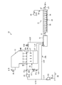
- FIG. 1 is a schematic diagram illustrating a configuration of a seawater flue gas desulfurization system according to a first embodiment of the present invention.
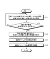
- FIG. 2 is a diagram illustrating an example of an operation method for adjusting the exhaust gas desulfurization rate.
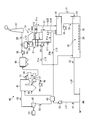
- FIG. 3 is a schematic diagram illustrating a configuration of a power generation system according to Embodiment 2 of the present invention.
- FIG. 1 is a schematic diagram showing the configuration of a seawater flue gas desulfurization system.
- the seawater flue gas desulfurization system 10 includes a flue gas desulfurization absorption tower 11, a dilution mixing tank 12, and an oxidation tank 13.
- the seawater 21 is pumped from the sea 22 to the seawater supply line L11 by the pump 23, a part of the seawater 21a is supplied to the flue gas desulfurization absorption tower 11 by the pump 24 via the seawater supply line L12, and the other remaining seawater 21b is It is supplied to the diluted mixing tank 12 through the diluted seawater supply line L13.
- seawater 21 seawater pumped directly from the sea 22 by the pump 23 is used, but the present invention is not limited to this, and the seawater 21 drained from a condenser (not shown) is used. It may be.
- the flue gas desulfurization absorption tower 11 is a tower that purifies the exhaust gas 25 by gas-liquid contact between the exhaust gas 25 and the seawater 21a.
- the seawater 21a is ejected in a liquid column shape above the spray nozzle 26, and the exhaust gas 25 and the seawater 21a supplied via the seawater supply line L12 are brought into gas-liquid contact. Desulfurization of sulfur is performed.
- the spray nozzle 26 is a spray nozzle that ejects upward in the form of a liquid column, but is not limited thereto, and may be sprayed downward in the form of a shower.
- the exhaust gas 25 and seawater 21a are brought into gas-liquid contact in the flue gas desulfurization absorption tower 11 to cause a reaction as shown in the following formula (I), and are contained in the form of SO 2 or the like in the exhaust gas 25.
- the sulfur content such as SOx is absorbed by the seawater 21a, and the sulfur content in the exhaust gas 25 is removed using the seawater 21a.
- the sulfur-absorbing seawater 27 stored at the bottom of the flue gas desulfurization absorption tower 11 is fed to the dilution mixing tank 12 via the sulfur-absorbing seawater discharge line L14.
- the sulfur-absorbing seawater 27 is mixed with the seawater 21b supplied to the dilution / mixing tank 12 and diluted.
- the purified gas 29 desulfurized by the flue gas desulfurization absorption tower 11 is released into the atmosphere through the purified gas discharge passage L15.
- the seawater supply line L12 is provided with a surplus seawater branch pipe L21, L22, or both.
- the surplus seawater branch pipe L21 is connected to the seawater supply line L12 at a branch portion 28A between the pump 24 of the seawater supply line L12 and the flue gas desulfurization absorption tower 11.
- the surplus seawater branch pipe L22 is connected to the branch portion 28B of the seawater supply line L12 in the flue gas desulfurization absorption tower 11.
- the surplus seawater 21c extracted from the surplus seawater branch pipes L21 and L22 is supplied to the dilution / mixing tank 12.
- the surplus seawater branch pipes L21 and L22 are provided with control valves V11 and V12 to adjust the amount of surplus seawater 21c extracted from the surplus seawater branch pipes L21 and L22.
- the amount of the seawater 21a supplied to the flue gas desulfurization absorption tower 11 can be easily adjusted.
- the desulfurization rate of the exhaust gas 25 in the flue gas desulfurization absorption tower 11 can be easily adjusted.
- the discharge pressure of the pump 24 is suppressed, the power for supplying the seawater 21a to the flue gas desulfurization absorption tower 11 can be reduced.
- the sulfur-absorbing seawater 27 is mixed to reduce the SO 2 concentration in the sulfur-absorbing seawater 27. Therefore, it is possible to reduce the re-scattering of SO 2 contained in the sulfur-absorbing seawater 27 in the dilution mixing tank 12 into the atmosphere.
- the desulfurization rate of the exhaust gas 25 is determined by the ratio of the inlet SO 2 concentration and the outlet SO 2 concentration in the exhaust gas 25 supplied to the flue gas desulfurization absorption tower 11 (outlet SO 2 concentration / inlet SO 2 concentration) or the sulfur content absorbing seawater 27. It adjusts with the quantity of the surplus seawater 21c extracted to the surplus seawater branch piping L21 and L22 based on the seawater property.
- the seawater property refers to the alkalinity, seawater temperature, pH, SO 4 concentration, etc. of the sulfur-absorbing seawater 27.
- Alkalinity refers to carbonate (H 2 CO 3 ), carbonate ion (CO 3 2 ⁇ ), bicarbonate ion (HCO 3 ⁇ ), OH ⁇ , organic acid or weak acid salt (silicic acid, phosphoric acid, boric acid) It is content of the component which consumes acids, such as.
- the desulfurization rate of the exhaust gas 25 is adjusted. Adjustment is made based on at least one of temperature, pH, and SO 4 concentration.
- the seawater properties are preferably adjusted based on alkalinity (HCO 3 ⁇ ).
- SO 2 concentration meters for measuring the inlet SO 2 concentration and the outlet SO 2 concentration of the exhaust gas 25 are provided at the inlet and outlet of the exhaust gas 25. Further, the flue gas desulfurization absorption tower 11 is provided with a thermometer, a pH measuring device, and an SO 4 concentration meter for measuring the seawater temperature, pH, and SO 4 concentration of the sulfur-absorbing seawater 27.
- FIG. 2 is a diagram illustrating an example of an operation method for adjusting the desulfurization rate of the exhaust gas 25.
- the desulfurization rate of the exhaust gas 25 and the seawater properties of the sulfur-absorbing seawater 27 in the flue gas desulfurization absorption tower 11 are obtained (step S11). It is determined whether or not the desulfurization rate of the exhaust gas 25 is equal to or greater than a predetermined threshold (for example, a set value + ⁇ ) (step S12).
- the predetermined threshold value of the desulfurization rate is, for example, a predetermined set value (for example, the desulfurization rate is 90%) that the flue gas desulfurization absorption tower 11 normally requires for desulfurization.
- the sum of ⁇ and (for example, the desulfurization rate is several percent).
- the spray amount necessary for spraying the seawater 21a is calculated from the seawater properties of the sulfur-absorbing seawater 27 and the desulfurization rate of the exhaust gas 25. (Step S13).
- the opening degree of the control valves V11 and V12 is calculated based on the spray amount necessary for spraying the seawater 21a (step S14). Based on the calculated opening of the control valves V11, V12, the degree of opening / closing of the control valves V11, V12 is adjusted (step S15).
- the amount of seawater 21a supplied to the flue gas desulfurization absorption tower 11 can be adjusted by adjusting the degree of opening and closing of the control valves V11 and V12 based on the calculated opening of the control valves V11 and V12,
- the spray amount of the seawater 21a sprayed from the spray nozzle 26 can be easily adjusted. Thereby, as above-mentioned, in the flue gas desulfurization absorption tower 11, adjustment of the desulfurization rate of the waste gas 25 can be performed easily.
- the surplus seawater branch pipes L21 and L22 are connected to the dilution / mixing tank 12, and the surplus seawater 21c extracted from the surplus seawater branch pipes L21 and L22 is supplied to the dilution / mixing tank 12.
- the supply destination of the extracted surplus seawater 21c is not limited to the dilution mixing tank 12, but may be supplied to the bottom of the flue gas desulfurization absorption tower 11, or may be an oxidation tank You may make it send to 13 directly.
- the extracted surplus seawater 21c may be supplied to both the dilution mixing tank 12 and the tower bottom of the flue gas desulfurization absorption tower 11, or the oxidation tank 13 and the flue gas desulfurization absorption tower 11 may be supplied. You may make it send to both a tower bottom part.
- the extracted surplus seawater 21c may be supplied to the dilution mixing tank 12, the oxidation tank 13, and the tower bottoms of the flue gas desulfurization absorption tower 11.
- the dilution mixing tank 12 is a tank that is provided on the downstream side of the flue gas desulfurization absorption tower 11 and dilutes and mixes the sulfur-absorbing seawater 27 containing sulfur with the seawater 21b for dilution.
- the sulfur-absorbing seawater 27 containing the sulfur content generated by bringing the sulfur content in the exhaust gas 25 into contact with the seawater 21a and desulfurizing the seawater in the flue gas desulfurization absorption tower 11 is mixed and diluted with the seawater 21b. To do.
- the pH of the sulfur-absorbing diluted seawater 31 in the dilution mixing tank 12 can be raised, and re-emission of SO 2 gas can be prevented. Further, by preventing SO 2 from being diffused and leaking outside in the dilution / mixing tank 12, it is possible to prevent emission of an irritating odor.
- the sulfur content absorption diluted seawater 31 is fed to the oxidation tank 13 provided on the downstream side of the dilution mixing tank 12.
- the oxidation tank 13 is a tank that is provided on the downstream side of the dilution mixing tank 12 and has an aeration apparatus (aeration apparatus) 32 that performs water quality recovery processing of the sulfur content absorption diluted seawater 31.
- the aeration apparatus 32 includes an oxidizing air blower 34 that supplies air 33, an air diffuser 35 that supplies the air 33, and an oxidizing air nozzle 36 that supplies the air 33 to the sulfur content absorption diluted seawater 31 in the oxidation tank 13. It has.
- the external air 33 is sent from the oxidizing air nozzle 36 into the oxidation tank 13 through the air diffusion pipe 35 by the oxidizing air blower 34, and the oxygen is dissolved as shown in the following formula (II).
- the sulfur content in the sulfur content absorption diluted seawater 31 comes into contact with the air 33, and the oxidation reaction of bisulfite ions (HSO 3 ⁇ ) as shown in the following formulas (III) to (V) and the bicarbonate ions ( HCO 3 ⁇ ) decarboxylation reaction occurs, and the sulfur content absorption diluted seawater 31 is recovered in water quality to become water quality recovered seawater 37.
- bisulfite ions HSO 3 ⁇
- HCO 3 ⁇ bicarbonate ions
- the seawater flue gas desulfurization system 10 is configured such that the ratio of the inlet SO 2 concentration and the outlet SO 2 concentration of the exhaust gas 25 supplied to the flue gas desulfurization absorption tower 11 and the alkali of the sulfur content absorption seawater 27.
- the amount of surplus seawater 21c extracted to the surplus seawater branch pipes L21 and L22 based on the degree, the amount of seawater 21a sprayed from the spray nozzle 26 is adjusted to adjust the desulfurization rate of the exhaust gas 25. It can be done easily.
- the motive power which supplies the seawater 21a to the flue gas desulfurization absorption tower 11 can be reduced.
- seawater flue gas desulfurization system 10 it is possible to provide a seawater flue gas desulfurization device with high safety and reliability while maintaining a stable desulfurization rate of the exhaust gas 25.
- seawater flue gas desulfurization system for treating the seawater 21a used for the seawater desulfurization in the flue gas desulfurization absorption tower 11 has been described, but the present invention is not limited to this.
- Seawater flue gas desulfurization equipment is included in exhaust gas discharged from factories in various industries, power plants such as large and medium-sized thermal power plants, large boilers for electric utilities or general industrial boilers, steelworks, smelters, etc.
- the present invention can also be applied to a seawater flue gas desulfurization apparatus that desulfurizes sulfur oxides.
- the flue gas desulfurization absorption tower 11, the dilution mixing tank 12 and the oxidation tank 13 are independent as separate tanks, and the flue gas desulfurization absorption tower 11, the dilution mixing tank 12, the oxidation tank 13, and the like.
- the present embodiment is not limited to this, and the flue gas desulfurization absorption tower 11, the dilution mixing tank 12, and the oxidation tank 13 may be integrated into a single tank.
- the dilution mixing tank 12 and the oxidation tank 13 may be integrated into a single tank.
- a power generation system according to Example 2 of the present invention will be described with reference to the drawings.
- the seawater flue gas desulfurization system according to the first embodiment is used for the seawater flue gas desulfurization system applied to the power generation system according to the present embodiment.
- symbol is attached
- FIG. 3 is a schematic diagram illustrating a configuration of a power generation system according to Embodiment 2 of the present invention.
- a power generation system 40 according to this embodiment includes a boiler 41, a steam turbine 42, a condenser 43, a flue gas denitration device 44, a dust collector 45, and a seawater flue gas desulfurization system. 10.
- the sulfur-absorbing seawater 27 means used seawater that has absorbed sulfur such as SO 2 in the seawater flue gas desulfurization system 10.
- the boiler 41 injects and burns fuel 46 supplied from an oil tank or a coal mill from a burner (not shown) together with air 48 preheated by an air preheater (AH) 47.
- the air 48 supplied from the outside is supplied to the air preheater 47 by the pushing fan 49 and preheated.
- the fuel 46 and the air 48 preheated by the air preheater 47 are supplied to the burner, and the fuel 46 is burned by the boiler 41. Thereby, the steam 50 for driving the steam turbine 42 is generated.
- the exhaust gas 51 generated by combustion in the boiler 41 is sent to the flue gas denitration device 44. Further, the exhaust gas 51 is used as a heat source for exchanging heat with the water 52 discharged from the condenser 43 and generating steam 50.
- the steam turbine 42 uses this steam 50 to drive the generator 53.
- the condenser 43 collects the water 52 condensed by the steam turbine 42 and returns it to the boiler 41 for circulation.
- the exhaust gas 51 discharged from the boiler 41 is denitrated in the flue gas denitration device 44, exchanged heat with the air 48 by the air preheater 47, and then sent to the dust collector 45 to remove the dust in the exhaust gas 51.
- the exhaust gas 51 removed by the dust collector 45 is supplied into the seawater flue gas desulfurization system 10 by the induction fan 55.
- the exhaust gas 51 is heat-exchanged by the heat exchanger 56 with the purified gas 29 desulfurized and discharged by the seawater flue gas desulfurization system 10 and then supplied into the seawater flue gas desulfurization system 10.
- the exhaust gas 51 may be directly supplied to the seawater flue gas desulfurization system 10 without exchanging heat with the purified gas 29 by the heat exchanger 56.
- the heat exchanger 56 includes a heat recovery device and a reheater, and a heat medium circulates between the heat recovery device and the reheater.
- the heat recovery unit is provided between the air preheater 47 and the dust collector 45 and exchanges heat between the exhaust gas 51 discharged from the boiler 41 and the heat medium.
- the reheater is provided on the downstream side of the flue gas desulfurization absorption tower 11, and exchanges heat between the purified gas 57 discharged from the flue gas desulfurization absorption tower 11 and the heat medium to reheat the purified gas 29. To do.
- the seawater flue gas desulfurization system 10 is the seawater flue gas desulfurization apparatus according to Example 1 described above. That is, the seawater flue gas desulfurization system 10 includes the flue gas desulfurization absorption tower 11, the dilution mixing tank 12, the oxidation tank 13, and the surplus seawater branch pipes L21 and L22.
- seawater desulfurization is performed using the seawater 21 pumped up from the sea 22 by the sulfur content contained in the exhaust gas 51. Further, the seawater 21 is pumped from the sea 22 by the pump 23 and heat exchange is performed by the condenser 43, and then a part of the seawater 21a is sent to the seawater flue gas desulfurization system 10 by the pump 24 via the seawater supply line L12. The The remaining seawater 21b is fed to the upstream side of the dilution / mixing tank 12 via the seawater supply line L13.
- the exhaust gas 51 and the seawater 21a are brought into gas-liquid contact, and the sulfur content in the exhaust gas 51 is absorbed by the seawater 21a.
- the sulfur-absorbing seawater 27 that has absorbed the sulfur is fed from the flue gas desulfurization absorption tower 11 to the upstream side of the dilution mixing tank 12, mixed with the seawater 21b, and diluted.
- the exhaust gas 51 purified by the seawater flue gas desulfurization system 10 becomes the purified gas 29 and is discharged from the chimney 57 through the purified gas discharge passage L15.
- the seawater flue gas desulfurization system 10 is provided with surplus seawater branch pipes L21 and L22 in the seawater supply line L12.
- the surplus seawater branch pipe L21 is connected to the seawater supply line L12 between the pump 24 of the seawater supply line L12 and the flue gas desulfurization absorption tower 11.
- the surplus seawater branch pipe L22 is connected to the seawater supply line L12 in the flue gas desulfurization absorption tower 11.
- the surplus seawater 21c extracted from the surplus seawater branch pipes L21 and L22 is supplied to the dilution / mixing tank 12.
- the desulfurization rate of the exhaust gas 51 is adjusted.
- the desulfurization rate of the exhaust gas 25 is determined by the ratio of the inlet SO 2 concentration and the outlet SO 2 concentration in the exhaust gas 51 supplied to the flue gas desulfurization absorption tower 11 (outlet SO 2 concentration / inlet SO 2 concentration) and sulfur.
- the seawater 21 pumped from the sea 22 is heat-exchanged by the condenser 43 and then sent to the seawater flue gas desulfurization system 10 for use in seawater desulfurization.
- the seawater 21 pumped from the sea 22 is condensed into water. Instead of heat exchange in the vessel 43, it may be directly fed to the seawater flue gas desulfurization system 10 and used for seawater desulfurization.
- the sulfur-absorbing seawater 27 is mixed with the seawater 21b in the dilution / mixing tank 12, and the diluted sulfur-absorbing / diluting seawater 31 is supplied to the oxidation tank 13 to recover the water content of the sulfur-absorbing diluted seawater 31 in the oxidation tank 13.
- Water quality recovery seawater 37 The water quality recovery seawater 37 obtained in the oxidation tank 13 is discharged from the oxidation tank 13 to the sea 22 via the seawater discharge line L32 with pH, dissolved oxygen concentration, and COD at a level at which seawater can be discharged.
- a part of the seawater 21 may be supplied from the seawater supply line L11 to the downstream side of the water quality recovery seawater 37 in the oxidation tank 13 via the diluted seawater supply line L13.
- the water quality recovery seawater 37 can be further diluted.
- the pH of the water quality recovery seawater 37 is increased, the pH of the seawater drainage liquid is increased to near the seawater, the drainage standard for the pH of the seawater drainage liquid (pH 6.0 or higher) is satisfied, and COD is reduced. It is possible to release the pH and COD of the water quality recovery seawater 37 as a level at which seawater can be discharged.
- the power generation system 40 it is possible to easily adjust the desulfurization rate of the exhaust gas 51 in the flue gas desulfurization absorption tower 11, and supply the seawater 21a to the flue gas desulfurization absorption tower 11.
- the driving power can be reduced and the running cost can be suppressed.
- excess seawater 21c withdrawn in excess seawater branch pipe L21, L22 is supplied to the dilution mixing tank 12, since it is possible to reduce the SO 2 concentration of sulfur in the absorbing seawater 27, sulfur in the dilution mixing tank 12 It is possible to reduce the re-scattering of SO 2 contained in the partial absorption seawater 27 into the atmosphere. Therefore, it is possible to provide a power generation system with high safety and reliability while maintaining a stable desulfurization rate of the exhaust gas 51.
- seawater flue gas desulfurization apparatus 10 is included in exhaust gas discharged from factories in various industries, power plants such as large and medium-sized thermal power plants, large boilers for electric utilities, or general industrial boilers. It can be used for removal of sulfur content in the sulfur content absorption solution produced by desulfurizing the sulfur oxide.
Landscapes
- Engineering & Computer Science (AREA)
- Chemical & Material Sciences (AREA)
- Life Sciences & Earth Sciences (AREA)
- General Engineering & Computer Science (AREA)
- Environmental & Geological Engineering (AREA)
- Mechanical Engineering (AREA)
- Organic Chemistry (AREA)
- Combustion & Propulsion (AREA)
- Hydrology & Water Resources (AREA)
- Water Supply & Treatment (AREA)
- Oil, Petroleum & Natural Gas (AREA)
- Thermal Sciences (AREA)
- Chemical Kinetics & Catalysis (AREA)
- General Chemical & Material Sciences (AREA)
- Sustainable Development (AREA)
- Sustainable Energy (AREA)
- Physics & Mathematics (AREA)
- Health & Medical Sciences (AREA)
- Analytical Chemistry (AREA)
- Biomedical Technology (AREA)
- Treating Waste Gases (AREA)
- Engine Equipment That Uses Special Cycles (AREA)
- Chimneys And Flues (AREA)
- Gas Separation By Absorption (AREA)
Abstract
本発明に係る海水排煙脱硫システム10は、排ガス25と海水21aとを気液接触して排ガス25を洗浄する排煙脱硫吸収塔11と、排煙脱硫吸収塔11の後流側に設けられ、硫黄分を含んだ硫黄分吸収海水27を海水21bと希釈混合する希釈混合槽12と、海水21aを排煙脱硫吸収塔11に供給する海水供給ラインL12と、排煙脱硫吸収塔11の塔内と塔外との何れか一方または両方で海水供給ラインL12から分岐し、海水21aを希釈混合槽12に供給する余剰海水分岐配管L21、L22とを有することを特徴とする。
Description
本発明は、石炭焚き、原油焚き及び重油焚き等の工業燃焼設備等から排出される排ガス中の硫黄酸化物を、海水を用いて脱硫する海水排煙脱硫システムおよび発電システムに関する。
石炭や原油等を燃料とする発電プラントにおいて、石炭等の化石燃料を燃焼することでボイラから排出される燃焼排気ガス(以下、「排ガス」と呼ぶ)には硫黄酸化物(SOx)など硫黄分が含まれる。そのため、排ガスは、脱硫処理され、排ガス中に含まれている二酸化硫黄(SO2)等のSOxを除去してから大気に放出される。このような脱硫処理方法として、石灰石石膏法、スプレードライヤー法及び海水法等がある。
発電所などは大量の冷却水を必要とするため海に面した場所に建設される場合が多い。そのため、脱硫処理に要する稼動コストを抑えることなどの観点から、海水を排ガス中の硫黄酸化物を吸収する吸収液として利用して脱硫を行う海水脱硫を用いた海水排煙脱硫装置が提案されている。
海水排煙脱硫装置は、略円筒のような筒形状又は角形状を縦置きにした脱硫塔(吸収塔)の内部に海水及びボイラ排ガスを供給し、海水を吸収液として気液接触させることでSOxを除去している。脱硫塔内で吸収剤として使用した脱硫後の海水(硫黄分吸収海水)は、たとえば、上部が開放された長い水路(Seawater Oxidation Treatment System;SOTS)内を流れ、海水と混合して希釈されて排出される。硫黄分吸収海水は、水路の一部の底面に設置したエアレーション装置から流出される微細気泡によって脱炭酸(爆気)される(例えば、特許文献1~3参照)。
海水排煙脱硫装置では、海水を用いて脱硫を行う場合、脱硫塔内に供給される排ガスと脱硫塔の外部に排出される排ガスとの比から求められる排ガスの脱硫率は、所定値(例えば、90%程度)となるように調整している。
海水を用いて脱硫を行う場合、海水のアルカリ度、海水温度、海水のpH、脱硫した海水中に含まれる硫酸イオン(SO4
2-)濃度などの海水性状に応じて、排ガスの脱硫率が所定値(例えば、90%程度)よりも高くなる場合がある。
海水を脱硫塔内に供給する際、海水の供給量の調整はポンプを運転する台数を変更して制御を行なうようにしているため、脱硫塔内に供給する海水の供給量の微調整は困難である。そのため、排ガスの脱硫率が所定値よりも高くなった場合、排ガスの脱硫率の微調整が困難である、という問題がある。
本発明は、前記課題に鑑み、排ガスの脱硫率の調整を容易に行うことができる海水排煙脱硫システムおよび発電システムを提供することを課題とする。
上述した課題を解決するための本発明の第1の発明は、排ガスと海水とを気液接触して前記排ガスを洗浄する排煙脱硫吸収塔と、前記排煙脱硫吸収塔の後流側に設けられ、硫黄分を含んだ硫黄分吸収海水を希釈用の海水と希釈混合する希釈混合槽と、前記海水を前記排煙脱硫吸収塔に供給する海水供給ラインと、前記排煙脱硫吸収塔の塔内と塔外との何れか一方または両方で前記海水供給ラインから分岐し、前記海水の一部を前記排煙脱硫吸収塔の塔底部又は前記希釈混合槽のいずれか一方又は両方に供給する余剰海水分岐配管と、前記余剰海水分岐配管に設置された余剰海水分岐量を調節する調節弁と、を有することを特徴とする海水排煙脱硫システムである。
第2の発明は、第1の発明において、前記余剰海水分岐配管の分岐部は、前記海水供給ラインに設けられる海水送給ポンプの後流側に設けられることを特徴とする海水排煙脱硫システムである。
第3の発明は、第1または第2の発明において、前記排煙脱硫吸収塔における脱硫率を算出して得られた脱硫率に基づいて、前記排煙脱硫吸収塔内に前記海水を噴霧する噴霧ノズルからの海水の噴霧量を算出し、前記余剰海水分岐配管に設置された調節弁の開度を調整することで、前記海水の噴霧量を調節することを特徴とする海水排煙脱硫システムである。
第4の発明は、第1から第3の何れか1つの発明において、前記排煙脱硫吸収塔、前記希釈混合槽および酸化槽が同一槽で構成されることを特徴とする海水排煙脱硫システムである。
第5の発明は、ボイラと、前記ボイラから排出される排ガスを蒸気発生用の熱源として使用すると共に、発生した蒸気を用いて発電機を駆動する蒸気タービンと、第1から第4の何れか1つの発明の海水排煙脱硫システムとを有し、前記蒸気タービンで凝縮した水を回収し、循環させる復水器と、前記ボイラから排出される排ガスの脱硝を行う排煙脱硝装置と、前記排ガス中の煤塵を除去する集塵装置と、前記排ガスと熱交換器内を循環する熱媒体とを熱交換する熱回収器と、前記排ガスと海水とを気液接触して前記排ガスを洗浄する排煙脱硫吸収塔から排出される浄化ガスと前記熱媒体とを熱交換して、前記浄化ガスを再加熱する再加熱器とを含む熱交換器と、前記海水排煙脱硫システムで脱硫された浄化ガスを外部へ排出する煙突との少なくとも1つを有することを特徴とする発電システムである。
本発明によれば、排ガスの脱硫率の調整を容易に行うことができる。
以下、本発明につき図面を参照しつつ詳細に説明する。なお、下記の実施例により本発明が限定されるものではない。また、下記実施例における構成要素には、当業者が容易に想定できるもの、実質的に同一のもの、いわゆる均等の範囲のものが含まれる。さらに、下記実施形態で開示した構成要素は適宜組み合わせることが可能である。
本発明による実施例1に係る海水排煙脱硫システムについて、図面を参照して説明する。図1は、海水排煙脱硫システムの構成を示す概略図である。図1に示すように、本実施例に係る海水排煙脱硫システム10は、排煙脱硫吸収塔11と、希釈混合槽12と、酸化槽13とを有する。
海水21は海22からポンプ23により海水供給ラインL11に汲み上げられ、一部の海水21aはポンプ24により海水供給ラインL12を介して排煙脱硫吸収塔11に供給され、他の残りの海水21bは希釈海水供給ラインL13を介して希釈混合槽12に供給される。海水21は、海22からポンプ23により直接汲み上げた海水を用いているが、本発明はこれに限定されるものではなく、図示しない復水器から排出される海水21の排液などを用いるようにしてもよい。
排煙脱硫吸収塔11は、排ガス25と海水21aとを気液接触して排ガス25を浄化する塔である。排煙脱硫吸収塔11では、海水21aは噴霧ノズル26より上方に液柱状に噴出させ、排ガス25と海水供給ラインL12を介して供給される海水21aとを気液接触させて、排ガス25中の硫黄分の脱硫を行っている。本実施例では、噴霧ノズル26は、上方に液柱状に噴出させる噴霧ノズルであるが、これに限定されるものではなく、下方にシャワー状に噴霧するようにしてもよい。
即ち、排煙脱硫吸収塔11において排ガス25と海水21aとを気液接触させて、下記式(I)に示すような反応を生じさせ、排ガス25中のSO2などの形態で含有されているSOxなどの硫黄分を海水21aに吸収させ、排ガス25中の硫黄分を、海水21aを用いて除去している。
SO2(G) + H2O → H2SO3(L) → HSO3 - + H+
・・・(I)
SO2(G) + H2O → H2SO3(L) → HSO3 - + H+
・・・(I)
この海水脱硫により海水21aと排ガス25との気液接触により発生したH2SO3が解離して水素イオン(H+)が海水21a中に遊離するためpHが下がり、硫黄分吸収海水27には多量の硫黄分が吸収される。このため、硫黄分吸収海水27は硫黄分を高濃度に含んでいる。このとき、硫黄分吸収海水27のpHとしては、例えば3~6程度となる。そして、排煙脱硫吸収塔11で硫黄分を吸収した硫黄分吸収海水27は、排煙脱硫吸収塔11の塔底部に貯留される。排煙脱硫吸収塔11の塔底部に貯留された硫黄分吸収海水27は、硫黄分吸収海水排出ラインL14を介して希釈混合槽12に送給される。希釈混合槽12で硫黄分吸収海水27は希釈混合槽12に供給される海水21bと混合され、希釈される。
また、排煙脱硫吸収塔11で脱硫された浄化ガス29は浄化ガス排出通路L15を介して大気中に放出される。
また、海水供給ラインL12には、余剰海水分岐配管L21、またはL22、あるいはその両方が設けられている。余剰海水分岐配管L21は、海水供給ラインL12のポンプ24と排煙脱硫吸収塔11との間の分岐部28Aで海水供給ラインL12と連結している。また、余剰海水分岐配管L22は、排煙脱硫吸収塔11内の海水供給ラインL12の分岐部28Bと連結している。余剰海水分岐配管L21、L22から抜き出された余剰海水21cは、希釈混合槽12に送給される。余剰海水分岐配管L21、L22には、調節弁V11、V12が設けられ、余剰海水分岐配管L21、L22から抜き出される余剰海水21cの量を調整している。
余剰海水分岐配管L21、L22により海水供給ラインL12から海水21aの一部を余剰海水21cとして抜き出すことで、排煙脱硫吸収塔11に供給される海水21aの量を容易に調整することができるため、排煙脱硫吸収塔11における排ガス25の脱硫率の調整を容易に行うことができる。また、ポンプ24の吐出圧が抑えられるため、海水21aを排煙脱硫吸収塔11に供給する動力を低減することができる。更に、余剰海水分岐配管L21、L22に抜き出される余剰海水21cは希釈混合槽12に供給されるため、硫黄分吸収海水27を混合し、硫黄分吸収海水27中のSO2濃度を低減することができることから、希釈混合槽12中の硫黄分吸収海水27中に含まれるSO2が大気中に再飛散することを低減することができる。
排ガス25の脱硫率は、排煙脱硫吸収塔11に供給される排ガス25中の入口SO2濃度と出口SO2濃度との比(出口SO2濃度/入口SO2濃度)や硫黄分吸収海水27の海水性状に基づいて余剰海水分岐配管L21、L22に抜き出される余剰海水21cの量により調整される。
本実施例において、海水性状とは、硫黄分吸収海水27のアルカリ度、海水温度、pH、SO4濃度などをいう。アルカリ度とは、炭酸(H2CO3)、炭酸イオン(CO3
2-)、炭酸水素イオン(HCO3
-)、OH-、有機酸や弱酸の塩(ケイ酸、リン酸、ホウ酸)などの酸を消費する成分の含有量である。排ガス25の脱硫率を硫黄分吸収海水27の海水性状に基づいて余剰海水分岐配管L21、L22に抜き出される余剰海水21cの量を調整する場合には、硫黄分吸収海水27のアルカリ度、海水温度、pH、SO4濃度の少なくとも1つ以上に基づいて調整される。中でも海水性状としては、アルカリ度(HCO3
-)に基づいて調整するのが好ましい。
排煙脱硫吸収塔11には、排ガス25の入口および出口には、排ガス25の入口SO2濃度および出口SO2濃度を測定するためのSO2濃度計が設けられている。また、排煙脱硫吸収塔11には、硫黄分吸収海水27の海水温度、pH、SO4濃度を測定するための温度計、pH測定器、SO4濃度計を設ける。
図2は、排ガス25の脱硫率を調整する運転方法の一例を示す図である。図2に示すように、排煙脱硫吸収塔11における排ガス25の脱硫率および硫黄分吸収海水27の海水性状を求める(ステップS11)。排ガス25の脱硫率が所定の閾値(例えば、設定値+α)以上か否かを判断する(ステップS12)。ここで、本実施例において、脱硫率の所定の閾値とは、例えば、排煙脱硫吸収塔11が、通常、脱硫に必要とされる所定の設定値(例えば、脱硫率が90%)と余分α(例えば、脱硫率が数%)との和の値をいう。
排ガス25の脱硫率が所定の閾値(例えば、設定値+α)以上の場合には、硫黄分吸収海水27の海水性状と排ガス25の脱硫率とから海水21aの噴霧に必要な噴霧量を算出する(ステップS13)。海水21aの噴霧に必要な噴霧量に基づいて調節弁V11、V12の開度を算出する(ステップS14)。算出された調節弁V11、V12の開度に基づいて調節弁V11、V12の開閉度を調整する(ステップS15)。
算出された調節弁V11、V12の開度に基づいて調節弁V11、V12の開閉度を調整することで、排煙脱硫吸収塔11に供給される海水21aの量を調整することができるため、噴霧ノズル26から噴霧される海水21aの噴霧量を容易に調整することができる。これにより、上述の通り、排煙脱硫吸収塔11において、排ガス25の脱硫率の調整を容易に行うことができる。
また、本実施例においては、余剰海水分岐配管L21、L22は、希釈混合槽12と連結し、余剰海水分岐配管L21、L22から抜き出された余剰海水21cは希釈混合槽12に送給するようにしているが、抜き出された余剰海水21cの供給先は希釈混合槽12に限定されるものではなく、排煙脱硫吸収塔11の塔底部に送給するようにしてもよいし、酸化槽13へ直接送給するようにしてもよい。また、抜き出された余剰海水21cは、希釈混合槽12と排煙脱硫吸収塔11の塔底部との両方に送給するようにしてもよいし、酸化槽13と排煙脱硫吸収塔11の塔底部との両方に送給するようにしてもよい。さらに、抜き出された余剰海水21cは、希釈混合槽12、酸化槽13および排煙脱硫吸収塔11の塔底部に送給するようにしてもよい。
希釈混合槽12は、排煙脱硫吸収塔11の後流側に設けられ、硫黄分を含んだ硫黄分吸収海水27を希釈用の海水21bと希釈・混合する槽である。希釈混合槽12において、排煙脱硫吸収塔11で排ガス25中の硫黄分を海水21aと接触させて海水脱硫することによって生じた硫黄分を含んだ硫黄分吸収海水27を海水21bと混合・希釈する。硫黄分吸収海水27を海水21bと混合し、希釈することで、希釈混合槽12内の硫黄分吸収希釈海水31のpHを上昇させ、SO2ガスの再放散を防ぐことができる。また、希釈混合槽12においてSO2が放散され、外部に漏洩するのを防止することで、刺激臭を放つのを防止することができる。
そして、硫黄分吸収希釈海水31は、希釈混合槽12の下流側に設けられている酸化槽13に送給される。酸化槽13は、希釈混合槽12の下流側に設けられ、硫黄分吸収希釈海水31の水質回復処理を行う曝気装置(エアレーション装置)32を有する槽である。
曝気装置32は、空気33を供給する酸化用空気ブロア34と、空気33を送給する散気管35と、空気33を酸化槽13内の硫黄分吸収希釈海水31に供給する酸化空気用ノズル36とを有するものである。酸化用空気ブロア34により外部の空気33が散気管35を介して酸化空気用ノズル36から酸化槽13内に送り込まれ、下記式(II)のような酸素の溶解を生じる。酸化槽13において硫黄分吸収希釈海水31中の硫黄分が空気33と接触して下記式(III)~(V)のような亜硫酸水素イオン(HSO3
-)の酸化反応と、重炭酸イオン(HCO3
-)の脱炭酸反応とを生じ、硫黄分吸収希釈海水31は水質回復され、水質回復海水37となる。
O2(G) → O2(L)・・・(II)
HSO3 - + 1/2O2 → SO4 2- + H+ ・・・(III)
HCO3 - + H+ → CO2(G) + H2O ・・・(IV)
CO3 2- +2H+ → CO2(G) + H2O ・・・(V)
O2(G) → O2(L)・・・(II)
HSO3 - + 1/2O2 → SO4 2- + H+ ・・・(III)
HCO3 - + H+ → CO2(G) + H2O ・・・(IV)
CO3 2- +2H+ → CO2(G) + H2O ・・・(V)
これにより、硫黄分吸収希釈海水31のpHを上昇させると共に、CODを低減することができ、水質回復海水37のpH、溶存酸素濃度、CODを海水放流可能なレベルとして放出することができる。また、酸化槽13で硫黄分吸収希釈海水31の水質回復を行う際にガスが発生しても、この発生するガスはSO2環境基準濃度を満たすようにして酸化槽13で放散させることができる。水質回復海水37は海水排出ラインL31を介して海22へ放流される。
このように、本実施例に係る海水排煙脱硫システム10は、排煙脱硫吸収塔11に供給される排ガス25の入口SO2濃度と出口SO2濃度との比および硫黄分吸収海水27のアルカリ度に基づいて余剰海水分岐配管L21、L22に抜き出される余剰海水21cの量を調整することで、噴霧ノズル26から噴霧される海水21aの噴霧量を調整して排ガス25の脱硫率の調整を容易に行うことができる。また、海水21aを排煙脱硫吸収塔11に供給する動力を低減することができる。更に、余剰海水21cを希釈混合槽12中の硫黄分吸収海水27に混合することで、硫黄分吸収海水27中のSO2濃度を低減することができる。このため、屋外開放型の酸化槽13に流れた硫黄分吸収海水27を酸化処理し水質回復を行う際、排煙脱硫吸収塔11において吸収したSO2が希釈混合槽12において放散され、SO2ガスが外部に漏洩するのを防止し、刺激臭を放つのを防止することができる。
したがって、本実施例に係る海水排煙脱硫システム10によれば、排ガス25の安定した脱硫率を維持しつつ、安全性および信頼性の高い海水排煙脱硫装置を提供することができる。
また、本実施例においては、排煙脱硫吸収塔11で海水脱硫に用いた海水21aの処理をする海水排煙脱硫システムについて説明したが、本発明はこれに限定されるものではない。海水排煙脱硫装置は、例えば各種産業における工場、大型、中型火力発電所などの発電所、電気事業用大型ボイラ又は一般産業用ボイラ、製鉄所、精錬所等から排出される排ガス中に含まれる硫黄酸化物を海水脱硫する海水排煙脱硫装置にも適用することができる。
また、本実施例においては、排煙脱硫吸収塔11、希釈混合槽12および酸化槽13は各々別々の槽として独立しており、排煙脱硫吸収塔11と希釈混合槽12と酸化槽13とを連結するようにしているが、本実施例はこれに限定されるものではなく、排煙脱硫吸収塔11、希釈混合槽12および酸化槽13を一体として一つの槽で構成してもよいし、希釈混合槽12と酸化槽13とを一体として一つの槽で構成するようにしてもよい。
本発明の実施例2に係る発電システムについて、図面を参照して説明する。本実施例に係る発電システムに適用される海水排煙脱硫システムには、実施例1に係る海水排煙脱硫システムが用いられる。なお、実施例1と同様の部材については、同一符号を付してその説明は省略する。
図3は、本発明の実施例2に係る発電システムの構成を示す概略図である。図3に示すように、本実施例に係る発電システム40は、ボイラ41と、蒸気タービン42と、復水器43と、排煙脱硝装置44と、集塵装置45と、海水排煙脱硫システム10とを有するものである。尚、本実施例において、上述のように、硫黄分吸収海水27とは、海水排煙脱硫システム10においてSO2など硫黄分を吸収した使用済み海水をいう。
ボイラ41は、油タンクまたは石炭ミルなどから供給される燃料46を空気予熱器(AH)47で予熱された空気48と共にバーナ(不図示)から噴射して燃焼させる。外部から供給される空気48は押込みファン49により空気予熱器47に送給され予熱される。燃料46と空気予熱器47で予熱された空気48とは前記バーナに供給され、燃料46はボイラ41で燃焼される。これにより、蒸気タービン42を駆動するための蒸気50を発生する。
ボイラ41内で燃焼して発生する排ガス51は排煙脱硝装置44に送給される。また、排ガス51は復水器43から排出される水52と熱交換し、蒸気50を発生する熱源として使用される。蒸気タービン42はこの蒸気50を用いて発電機53を駆動している。そして、復水器43は蒸気タービン42で凝縮した水52を回収し、再びボイラ41に戻し、循環させている。
ボイラ41から排出された排ガス51は排煙脱硝装置44内で脱硝され、空気予熱器47で空気48と熱交換した後、集塵装置45に送給され、排ガス51中の煤塵を除去する。そして、集塵装置45で除塵された排ガス51は、誘引ファン55により海水排煙脱硫システム10内に供給される。この時、排ガス51は熱交換器56で、海水排煙脱硫システム10で脱硫され排出される浄化ガス29と熱交換された後、海水排煙脱硫システム10内に供給される。また、排ガス51は熱交換器56で浄化ガス29と熱交換することなく海水排煙脱硫システム10に直接供給するようにしてもよい。
また、熱交換器56は、熱回収器と、再加熱器とを含むものであり、前記熱回収器と前記再加熱器との間を熱媒体が循環している。前記熱回収器は、空気予熱器47と集塵装置45との間に設けられ、ボイラ41から排出される排ガス51と前記熱媒体とを熱交換する。前記再加熱器は、排煙脱硫吸収塔11の後流側に設けられ、排煙脱硫吸収塔11から排出される浄化ガス57と前記熱媒体とを熱交換して、浄化ガス29を再加熱する。
海水排煙脱硫システム10は、上述の実施例1に係る海水排煙脱硫装置である。すなわち、海水排煙脱硫システム10は、排煙脱硫吸収塔11と、希釈混合槽12と、酸化槽13と、余剰海水分岐配管L21、L22とを有するものである。
海水排煙脱硫システム10では、上述の通り、排ガス51中に含有されている硫黄分を海22から汲み上げられた海水21を用いて海水脱硫を行っている。また、海水21は海22からポンプ23により汲み上げられ、復水器43で熱交換した後、一部の海水21aは海水供給ラインL12を介してポンプ24により海水排煙脱硫システム10に送給される。また、残りの海水21bは海水供給ラインL13を介して希釈混合槽12の上流側に送給される。海水排煙脱硫システム10において排ガス51と海水21aとを気液接触させて、排ガス51中の硫黄分を海水21aに吸収している。硫黄分を吸収した硫黄分吸収海水27は排煙脱硫吸収塔11から希釈混合槽12の上流側に送給され、海水21bと混合し、希釈される。
また、海水排煙脱硫システム10で浄化された排ガス51は、浄化ガス29となって浄化ガス排出通路L15を介して煙突57から外部に排出される。
本実施例では、海水排煙脱硫システム10は、海水供給ラインL12に余剰海水分岐配管L21、L22を設けている。余剰海水分岐配管L21は海水供給ラインL12のポンプ24と排煙脱硫吸収塔11との間で海水供給ラインL12と連結している。また、余剰海水分岐配管L22は排煙脱硫吸収塔11内の海水供給ラインL12と連結している。余剰海水分岐配管L21、L22から抜き出された余剰海水21cは希釈混合槽12に送給される。余剰海水分岐配管L21、L22により海水供給ラインL12から海水21aの一部を余剰海水21cとして抜き出すことで、排煙脱硫吸収塔11に供給される海水21aの量を調整し、排煙脱硫吸収塔11における排ガス51の脱硫率の調整を行う。排ガス25の脱硫率は、上述の通り、排煙脱硫吸収塔11に供給される排ガス51中の入口SO2濃度と出口SO2濃度との比(出口SO2濃度/入口SO2濃度)や硫黄分吸収海水27のアルカリ度に基づいて余剰海水分岐配管L21、L22に抜き出される余剰海水21cの量により調整される。よって、余剰海水分岐配管L21、L22により海水供給ラインL12から海水21aの一部を抜き出す量を容易に調整できるため、排煙脱硫吸収塔11に供給される海水21aの量を容易に調整することができる。このため、排煙脱硫吸収塔11における排ガス51の脱硫率の調整を容易に行うことができる。また、ポンプ24の吐出圧が抑えられるため、海水21aを排煙脱硫吸収塔11に供給する動力を低減することができる。
また、海22から汲み上げられた海水21は復水器43で熱交換した後、海水排煙脱硫システム10に送給し、海水脱硫に用いているが、海22から汲み上げた海水21を復水器43で熱交換させずに海水排煙脱硫システム10に直接送給し、海水脱硫に用いるようにしてもよい。
希釈混合槽12で硫黄分吸収海水27を海水21bと混合し、希釈された硫黄分吸収希釈海水31は、酸化槽13に送給され、酸化槽13で硫黄分吸収希釈海水31を水質回復し、水質回復海水37とする。酸化槽13で得られた水質回復海水37は、pH、溶存酸素濃度、CODを海水放流可能なレベルとして酸化槽13から海水排出ラインL32を介して海22へ放流される。
また、海水供給ラインL11から海水21の一部を、希釈海水供給ラインL13を介して酸化槽13内の水質回復海水37の後流側に供給するようにしてもよい。これにより、水質回復海水37を更に希釈することができる。これにより、水質回復海水37のpHを上昇させ、海水排液のpHを海水近くにまで上昇させ、海水排液のpHの排水基準(pH6.0以上)を満たすと共に、CODを低減することができ、水質回復海水37のpH、CODを海水放流可能なレベルとして放出することができる。
このように、本実施例に係る発電システム40によれば、排煙脱硫吸収塔11において排ガス51の脱硫率の調整を容易に行うことができると共に、海水21aを排煙脱硫吸収塔11へ供給する動力を低減しランニングコストの抑制を図ることができる。また、余剰海水分岐配管L21、L22に抜き出される余剰海水21cは希釈混合槽12に供給され、硫黄分吸収海水27中のSO2濃度を低減することができることから、希釈混合槽12中の硫黄分吸収海水27中に含まれるSO2が大気中に再飛散することを低減することができる。したがって、排ガス51の安定した脱硫率を維持しつつ、安全性および信頼性の高い発電システムを提供することができる。
また、本実施例に係る海水排煙脱硫装置10は、各種産業における工場、大型、中型火力発電所などの発電所、電気事業用大型ボイラ又は一般産業用ボイラ等から排出される排ガス中に含まれる硫黄酸化物を海水脱硫することで生じる硫黄分吸収溶液中の硫黄分の除去に利用することができる。
10 海水排煙脱硫システム
11 排煙脱硫吸収塔
12 希釈混合槽
13 酸化槽
21、21a、21b 海水
21c 余剰海水
22 海
23、24 ポンプ
25、51 排ガス
26 噴霧ノズル
27 硫黄分吸収海水
28A、28B 分岐部
29 浄化ガス
31 硫黄分吸収希釈海水
32 曝気装置(エアレーション装置)
33 空気
34 酸化用空気ブロア
35 散気管
36 酸化空気用ノズル
37 水質回復海水
40 発電システム
41 ボイラ
42 蒸気タービン
43 復水器
44 排煙脱硝装置
45 集塵装置
46 燃料
47 空気予熱器(AH)
48 空気
49 押込みファン
50 蒸気
52 水
53 発電機
55 誘引ファン
56 熱交換器
57 煙突
L11、L12 海水供給ライン
L13 希釈海水供給ライン
L14 硫黄分吸収海水排出ライン
L15 浄化ガス排出通路
L21、L22 余剰海水分岐配管
L31、L32 海水排出ライン
Claims (5)
- 排ガスと海水とを気液接触して前記排ガスを洗浄する排煙脱硫吸収塔と、
前記排煙脱硫吸収塔の後流側に設けられ、硫黄分を含んだ硫黄分吸収海水を希釈用の海水と希釈混合する希釈混合槽と、
前記海水を前記排煙脱硫吸収塔に供給する海水供給ラインと、
前記排煙脱硫吸収塔の塔内と塔外との何れか一方または両方で前記海水供給ラインから分岐し、前記海水の一部を前記排煙脱硫吸収塔の塔底部又は前記希釈混合槽のいずれか一方又は両方に供給する余剰海水分岐配管と、前記余剰海水分岐配管に設置された余剰海水分岐量を調節する調節弁と、
を有することを特徴とする海水排煙脱硫システム。 - 請求項1において、
前記余剰海水分岐配管の分岐部は、前記海水供給ラインに設けられる海水送給ポンプの後流側に設けられることを特徴とする海水排煙脱硫システム。 - 請求項1または2において、
前記排煙脱硫吸収塔における脱硫率を算出して得られた脱硫率に基づいて、前記排煙脱硫吸収塔内に前記海水を噴霧する噴霧ノズルからの海水の噴霧量を算出し、前記余剰海水分岐配管に設置された調節弁の開度を調整することで、前記海水の噴霧量を調節することを特徴とする海水排煙脱硫システム。 - 請求項1から3の何れか1つにおいて、
前記排煙脱硫吸収塔、前記希釈混合槽および酸化槽が同一槽で構成されることを特徴とする海水排煙脱硫システム。 - ボイラと、
前記ボイラから排出される排ガスを蒸気発生用の熱源として使用すると共に、発生した蒸気を用いて発電機を駆動する蒸気タービンと、
請求項1から4の何れか1つの海水排煙脱硫システムとを有し、
前記蒸気タービンで凝縮した水を回収し、循環させる復水器と、
前記ボイラから排出される排ガスの脱硝を行う排煙脱硝装置と、
前記排ガス中の煤塵を除去する集塵装置と、
前記排ガスと熱交換器内を循環する熱媒体とを熱交換する熱回収器と、前記排ガスと海水とを気液接触して前記排ガスを洗浄する排煙脱硫吸収塔から排出される浄化ガスと前記熱媒体とを熱交換して、前記浄化ガスを再加熱する再加熱器とを含む熱交換器と、
前記海水排煙脱硫システムで脱硫された浄化ガスを外部へ排出する煙突との少なくとも1つを有することを特徴とする発電システム。
Priority Applications (1)
| Application Number | Priority Date | Filing Date | Title |
|---|---|---|---|
| CN201180061109.0A CN103282101B (zh) | 2011-02-28 | 2011-08-25 | 海水排烟脱硫系统及发电系统 |
Applications Claiming Priority (2)
| Application Number | Priority Date | Filing Date | Title |
|---|---|---|---|
| JP2011042962A JP5773687B2 (ja) | 2011-02-28 | 2011-02-28 | 海水排煙脱硫システムおよび発電システム |
| JP2011-042962 | 2011-02-28 |
Publications (1)
| Publication Number | Publication Date |
|---|---|
| WO2012117586A1 true WO2012117586A1 (ja) | 2012-09-07 |
Family
ID=46757540
Family Applications (1)
| Application Number | Title | Priority Date | Filing Date |
|---|---|---|---|
| PCT/JP2011/069148 WO2012117586A1 (ja) | 2011-02-28 | 2011-08-25 | 海水排煙脱硫システムおよび発電システム |
Country Status (5)
| Country | Link |
|---|---|
| JP (1) | JP5773687B2 (ja) |
| CN (1) | CN103282101B (ja) |
| CL (1) | CL2013001879A1 (ja) |
| TW (1) | TWI482657B (ja) |
| WO (1) | WO2012117586A1 (ja) |
Cited By (2)
| Publication number | Priority date | Publication date | Assignee | Title |
|---|---|---|---|---|
| CN104736225A (zh) * | 2013-01-29 | 2015-06-24 | 富士电机株式会社 | 气体洗涤器的海水量控制装置、气体洗涤器的海水量控制方法、碱量控制装置及碱量控制方法 |
| CN105899281A (zh) * | 2014-07-18 | 2016-08-24 | 富士电机株式会社 | 洗涤器的海水量控制装置、洗涤器的海水量控制方法及碱量控制装置 |
Families Citing this family (10)
| Publication number | Priority date | Publication date | Assignee | Title |
|---|---|---|---|---|
| JP5892265B2 (ja) | 2012-12-19 | 2016-03-23 | 富士電機株式会社 | 排ガス浄化装置 |
| JP2014233702A (ja) * | 2013-06-04 | 2014-12-15 | 三菱重工業株式会社 | 海水脱硫装置及び海水脱硫システム |
| JP6302191B2 (ja) * | 2013-09-02 | 2018-03-28 | 三菱日立パワーシステムズ株式会社 | 発電システム |
| CN104162361A (zh) * | 2014-07-29 | 2014-11-26 | 江苏南极机械有限责任公司 | 一种利用海水吸收净化柴油机尾气中so2的装置及吸收方法 |
| EP3189883B1 (en) | 2014-09-02 | 2019-09-04 | Fuji Electric Co., Ltd. | Exhaust gas treatment device and waste water treatment method for exhaust gas treatment device |
| JP6632452B2 (ja) * | 2016-03-31 | 2020-01-22 | 三菱日立パワーシステムズ株式会社 | 充填塔用の充填物及び海水脱硫装置 |
| EP3604116A4 (en) * | 2017-03-24 | 2021-01-20 | Mitsubishi Shipbuilding Co., Ltd. | MARINE DESULFURATION DEVICE DRAINAGE SYSTEM |
| KR20180131548A (ko) * | 2017-03-28 | 2018-12-10 | 미츠비시 히타치 파워 시스템즈 가부시키가이샤 | 선박용 탈황 장치, 선각 일체형 탈황 장치, 선박 및 선각 일체형 탈황 장치의 선박에 대한 설치 방법 |
| KR101918663B1 (ko) | 2018-04-18 | 2018-11-14 | 주식회사 지스코 | 발전시스템 |
| CN113198294B (zh) * | 2021-05-21 | 2021-11-19 | 华能国际电力股份有限公司大连电厂 | 一种海水脱硫控制方法和设备 |
Citations (5)
| Publication number | Priority date | Publication date | Assignee | Title |
|---|---|---|---|---|
| JPH11244646A (ja) * | 1998-03-05 | 1999-09-14 | Ishikawajima Harima Heavy Ind Co Ltd | 排煙脱硫装置の吸収剤スラリー流量制御方法及び装置 |
| JP2005066505A (ja) * | 2003-08-26 | 2005-03-17 | Mitsubishi Heavy Ind Ltd | 排ガス処理装置および処理方法 |
| JP2008207149A (ja) * | 2007-02-28 | 2008-09-11 | Mitsubishi Heavy Ind Ltd | 海水排煙脱硫システム |
| JP2010125377A (ja) * | 2008-11-27 | 2010-06-10 | Babcock Hitachi Kk | 湿式脱硫装置 |
| US20100206171A1 (en) * | 2008-06-13 | 2010-08-19 | Sigan Peng | Ship flue gas desulphurization method and equipment |
-
2011
- 2011-02-28 JP JP2011042962A patent/JP5773687B2/ja not_active Expired - Fee Related
- 2011-08-25 WO PCT/JP2011/069148 patent/WO2012117586A1/ja active Application Filing
- 2011-08-25 CN CN201180061109.0A patent/CN103282101B/zh not_active Expired - Fee Related
- 2011-11-28 TW TW100143573A patent/TWI482657B/zh not_active IP Right Cessation
-
2013
- 2013-06-25 CL CL2013001879A patent/CL2013001879A1/es unknown
Patent Citations (5)
| Publication number | Priority date | Publication date | Assignee | Title |
|---|---|---|---|---|
| JPH11244646A (ja) * | 1998-03-05 | 1999-09-14 | Ishikawajima Harima Heavy Ind Co Ltd | 排煙脱硫装置の吸収剤スラリー流量制御方法及び装置 |
| JP2005066505A (ja) * | 2003-08-26 | 2005-03-17 | Mitsubishi Heavy Ind Ltd | 排ガス処理装置および処理方法 |
| JP2008207149A (ja) * | 2007-02-28 | 2008-09-11 | Mitsubishi Heavy Ind Ltd | 海水排煙脱硫システム |
| US20100206171A1 (en) * | 2008-06-13 | 2010-08-19 | Sigan Peng | Ship flue gas desulphurization method and equipment |
| JP2010125377A (ja) * | 2008-11-27 | 2010-06-10 | Babcock Hitachi Kk | 湿式脱硫装置 |
Cited By (5)
| Publication number | Priority date | Publication date | Assignee | Title |
|---|---|---|---|---|
| CN104736225A (zh) * | 2013-01-29 | 2015-06-24 | 富士电机株式会社 | 气体洗涤器的海水量控制装置、气体洗涤器的海水量控制方法、碱量控制装置及碱量控制方法 |
| US10150078B2 (en) | 2013-01-29 | 2018-12-11 | Fuji Electric Co., Ltd. | Amount of seawater control device for scrubber, amount of seawater control method for scrubber, and amount of alkali control device and amount of alkali control method |
| CN105899281A (zh) * | 2014-07-18 | 2016-08-24 | 富士电机株式会社 | 洗涤器的海水量控制装置、洗涤器的海水量控制方法及碱量控制装置 |
| US10099175B2 (en) | 2014-07-18 | 2018-10-16 | Fuji Electric Co., Ltd. | Amount-of-seawater control device for scrubber, amount-of-seawater control method for scrubber, and amount-of-alkali control device |
| CN105899281B (zh) * | 2014-07-18 | 2018-12-14 | 富士电机株式会社 | 洗涤器的海水量控制装置、洗涤器的海水量控制方法及碱量控制装置 |
Also Published As
| Publication number | Publication date |
|---|---|
| TW201238644A (en) | 2012-10-01 |
| CN103282101A (zh) | 2013-09-04 |
| CN103282101B (zh) | 2015-06-03 |
| CL2013001879A1 (es) | 2013-11-29 |
| JP5773687B2 (ja) | 2015-09-02 |
| JP2012179521A (ja) | 2012-09-20 |
| TWI482657B (zh) | 2015-05-01 |
Similar Documents
| Publication | Publication Date | Title |
|---|---|---|
| JP5773687B2 (ja) | 海水排煙脱硫システムおよび発電システム | |
| JP2012179521A5 (ja) | ||
| WO2013115107A1 (ja) | 海水排煙脱硫システムおよび発電システム | |
| CN101063527B (zh) | 控制烟道气中水分浓度的方法 | |
| JP4959303B2 (ja) | 排気ガスの処理方法及び処理装置 | |
| KR101732298B1 (ko) | 배기 가스 중의 SOx의 감소를 위한 정화 시스템 및 방법 | |
| WO2010116482A1 (ja) | 海水脱硫酸化処理装置、脱硫海水の処理方法及びこれを適用した発電システム | |
| TWI531538B (zh) | Oxidation tank, seawater desulfurization system and power generation system | |
| JP2012239958A (ja) | 湿式排煙脱硫装置と方法 | |
| JP2012050931A (ja) | 排煙処理装置及び排煙処理方法 | |
| JP2013244454A (ja) | 排ガス処理装置 | |
| JP2013086054A (ja) | 海水利用の湿式石灰石−石膏法脱硫装置 | |
| WO2013118683A1 (ja) | 脱硫海水処理システム | |
| JP2015142912A (ja) | 亜硫酸ガス含有排ガスの脱硫方法および脱硫装置 | |
| JP2010269277A (ja) | 脱硫装置における水銀再放出抑制方法および装置 | |
| WO2010131327A1 (ja) | 海水排煙脱硫装置及び脱硫海水の処理方法 | |
| JP2009172541A (ja) | 湿式排煙脱硫装置の酸化用空気供給量制御方法 | |
| JP2010240624A (ja) | 排煙脱硫装置及び排ガス処理方法 | |
| CN102343209B (zh) | 应用锅炉排污水的烟气海水脱硫系统 | |
| JP2010112679A (ja) | ボイラプラント | |
| JP3813835B2 (ja) | 燃焼排ガスからの水回収システム | |
| JP5991664B2 (ja) | 排煙脱硫システム | |
| JP2009095698A (ja) | 排ガス脱硫装置における石膏スラリー・石灰石スラリーの張込み方法 | |
| JP2009095696A (ja) | 排ガス脱硫装置酸化塔のバイパス運転方法 | |
| JP2014121685A (ja) | 排ガス処理装置 |
Legal Events
| Date | Code | Title | Description |
|---|---|---|---|
| 121 | Ep: the epo has been informed by wipo that ep was designated in this application |
Ref document number: 11859882 Country of ref document: EP Kind code of ref document: A1 |
|
| NENP | Non-entry into the national phase |
Ref country code: DE |
|
| 122 | Ep: pct application non-entry in european phase |
Ref document number: 11859882 Country of ref document: EP Kind code of ref document: A1 |