WO2012114532A1 - 溶接継手の製造方法及び溶接継手 - Google Patents
溶接継手の製造方法及び溶接継手 Download PDFInfo
- Publication number
- WO2012114532A1 WO2012114532A1 PCT/JP2011/054664 JP2011054664W WO2012114532A1 WO 2012114532 A1 WO2012114532 A1 WO 2012114532A1 JP 2011054664 W JP2011054664 W JP 2011054664W WO 2012114532 A1 WO2012114532 A1 WO 2012114532A1
- Authority
- WO
- WIPO (PCT)
- Prior art keywords
- welding
- joint
- welded
- weld
- weld metal
- Prior art date
- Legal status (The legal status is an assumption and is not a legal conclusion. Google has not performed a legal analysis and makes no representation as to the accuracy of the status listed.)
- Ceased
Links
Images


Classifications
-
- B—PERFORMING OPERATIONS; TRANSPORTING
- B23—MACHINE TOOLS; METAL-WORKING NOT OTHERWISE PROVIDED FOR
- B23K—SOLDERING OR UNSOLDERING; WELDING; CLADDING OR PLATING BY SOLDERING OR WELDING; CUTTING BY APPLYING HEAT LOCALLY, e.g. FLAME CUTTING; WORKING BY LASER BEAM
- B23K31/00—Processes relevant to this subclass, specially adapted for particular articles or purposes, but not covered by only one of the preceding main groups
- B23K31/02—Processes relevant to this subclass, specially adapted for particular articles or purposes, but not covered by only one of the preceding main groups relating to soldering or welding
-
- B—PERFORMING OPERATIONS; TRANSPORTING
- B23—MACHINE TOOLS; METAL-WORKING NOT OTHERWISE PROVIDED FOR
- B23K—SOLDERING OR UNSOLDERING; WELDING; CLADDING OR PLATING BY SOLDERING OR WELDING; CUTTING BY APPLYING HEAT LOCALLY, e.g. FLAME CUTTING; WORKING BY LASER BEAM
- B23K33/00—Specially-profiled edge portions of workpieces for making soldering or welding connections; Filling the seams formed thereby
- B23K33/004—Filling of continuous seams
-
- B—PERFORMING OPERATIONS; TRANSPORTING
- B23—MACHINE TOOLS; METAL-WORKING NOT OTHERWISE PROVIDED FOR
- B23K—SOLDERING OR UNSOLDERING; WELDING; CLADDING OR PLATING BY SOLDERING OR WELDING; CUTTING BY APPLYING HEAT LOCALLY, e.g. FLAME CUTTING; WORKING BY LASER BEAM
- B23K35/00—Rods, electrodes, materials, or media, for use in soldering, welding, or cutting
- B23K35/22—Rods, electrodes, materials, or media, for use in soldering, welding, or cutting characterised by the composition or nature of the material
- B23K35/24—Selection of soldering or welding materials proper
- B23K35/30—Selection of soldering or welding materials proper with the principal constituent melting at less than 1550 degrees C
-
- B—PERFORMING OPERATIONS; TRANSPORTING
- B23—MACHINE TOOLS; METAL-WORKING NOT OTHERWISE PROVIDED FOR
- B23K—SOLDERING OR UNSOLDERING; WELDING; CLADDING OR PLATING BY SOLDERING OR WELDING; CUTTING BY APPLYING HEAT LOCALLY, e.g. FLAME CUTTING; WORKING BY LASER BEAM
- B23K9/00—Arc welding or cutting
- B23K9/02—Seam welding; Backing means; Inserts
- B23K9/025—Seam welding; Backing means; Inserts for rectilinear seams
- B23K9/0256—Seam welding; Backing means; Inserts for rectilinear seams for welding ribs on plates
-
- B—PERFORMING OPERATIONS; TRANSPORTING
- B23—MACHINE TOOLS; METAL-WORKING NOT OTHERWISE PROVIDED FOR
- B23K—SOLDERING OR UNSOLDERING; WELDING; CLADDING OR PLATING BY SOLDERING OR WELDING; CUTTING BY APPLYING HEAT LOCALLY, e.g. FLAME CUTTING; WORKING BY LASER BEAM
- B23K9/00—Arc welding or cutting
- B23K9/16—Arc welding or cutting making use of shielding gas
- B23K9/167—Arc welding or cutting making use of shielding gas and of a non-consumable electrode
-
- B—PERFORMING OPERATIONS; TRANSPORTING
- B23—MACHINE TOOLS; METAL-WORKING NOT OTHERWISE PROVIDED FOR
- B23K—SOLDERING OR UNSOLDERING; WELDING; CLADDING OR PLATING BY SOLDERING OR WELDING; CUTTING BY APPLYING HEAT LOCALLY, e.g. FLAME CUTTING; WORKING BY LASER BEAM
- B23K9/00—Arc welding or cutting
- B23K9/16—Arc welding or cutting making use of shielding gas
- B23K9/173—Arc welding or cutting making use of shielding gas and of a consumable electrode
-
- B—PERFORMING OPERATIONS; TRANSPORTING
- B23—MACHINE TOOLS; METAL-WORKING NOT OTHERWISE PROVIDED FOR
- B23K—SOLDERING OR UNSOLDERING; WELDING; CLADDING OR PLATING BY SOLDERING OR WELDING; CUTTING BY APPLYING HEAT LOCALLY, e.g. FLAME CUTTING; WORKING BY LASER BEAM
- B23K9/00—Arc welding or cutting
- B23K9/23—Arc welding or cutting taking account of the properties of the materials to be welded
-
- B—PERFORMING OPERATIONS; TRANSPORTING
- B24—GRINDING; POLISHING
- B24C—ABRASIVE OR RELATED BLASTING WITH PARTICULATE MATERIAL
- B24C1/00—Methods for use of abrasive blasting for producing particular effects; Use of auxiliary equipment in connection with such methods
- B24C1/10—Methods for use of abrasive blasting for producing particular effects; Use of auxiliary equipment in connection with such methods for compacting surfaces, e.g. shot-peening
-
- C—CHEMISTRY; METALLURGY
- C21—METALLURGY OF IRON
- C21D—MODIFYING THE PHYSICAL STRUCTURE OF FERROUS METALS; GENERAL DEVICES FOR HEAT TREATMENT OF FERROUS OR NON-FERROUS METALS OR ALLOYS; MAKING METAL MALLEABLE, e.g. BY DECARBURISATION OR TEMPERING
- C21D1/00—General methods or devices for heat treatment, e.g. annealing, hardening, quenching or tempering
- C21D1/34—Methods of heating
- C21D1/40—Direct resistance heating
-
- C—CHEMISTRY; METALLURGY
- C21—METALLURGY OF IRON
- C21D—MODIFYING THE PHYSICAL STRUCTURE OF FERROUS METALS; GENERAL DEVICES FOR HEAT TREATMENT OF FERROUS OR NON-FERROUS METALS OR ALLOYS; MAKING METAL MALLEABLE, e.g. BY DECARBURISATION OR TEMPERING
- C21D1/00—General methods or devices for heat treatment, e.g. annealing, hardening, quenching or tempering
- C21D1/34—Methods of heating
- C21D1/42—Induction heating
-
- C—CHEMISTRY; METALLURGY
- C21—METALLURGY OF IRON
- C21D—MODIFYING THE PHYSICAL STRUCTURE OF FERROUS METALS; GENERAL DEVICES FOR HEAT TREATMENT OF FERROUS OR NON-FERROUS METALS OR ALLOYS; MAKING METAL MALLEABLE, e.g. BY DECARBURISATION OR TEMPERING
- C21D7/00—Modifying the physical properties of iron or steel by deformation
- C21D7/02—Modifying the physical properties of iron or steel by deformation by cold working
- C21D7/04—Modifying the physical properties of iron or steel by deformation by cold working of the surface
- C21D7/06—Modifying the physical properties of iron or steel by deformation by cold working of the surface by shot-peening or the like
-
- C—CHEMISTRY; METALLURGY
- C21—METALLURGY OF IRON
- C21D—MODIFYING THE PHYSICAL STRUCTURE OF FERROUS METALS; GENERAL DEVICES FOR HEAT TREATMENT OF FERROUS OR NON-FERROUS METALS OR ALLOYS; MAKING METAL MALLEABLE, e.g. BY DECARBURISATION OR TEMPERING
- C21D9/00—Heat treatment, e.g. annealing, hardening, quenching or tempering, adapted for particular articles; Furnaces therefor
- C21D9/50—Heat treatment, e.g. annealing, hardening, quenching or tempering, adapted for particular articles; Furnaces therefor for welded joints
-
- C—CHEMISTRY; METALLURGY
- C22—METALLURGY; FERROUS OR NON-FERROUS ALLOYS; TREATMENT OF ALLOYS OR NON-FERROUS METALS
- C22C—ALLOYS
- C22C38/00—Ferrous alloys, e.g. steel alloys
- C22C38/02—Ferrous alloys, e.g. steel alloys containing silicon
-
- C—CHEMISTRY; METALLURGY
- C22—METALLURGY; FERROUS OR NON-FERROUS ALLOYS; TREATMENT OF ALLOYS OR NON-FERROUS METALS
- C22C—ALLOYS
- C22C38/00—Ferrous alloys, e.g. steel alloys
- C22C38/04—Ferrous alloys, e.g. steel alloys containing manganese
-
- C—CHEMISTRY; METALLURGY
- C22—METALLURGY; FERROUS OR NON-FERROUS ALLOYS; TREATMENT OF ALLOYS OR NON-FERROUS METALS
- C22C—ALLOYS
- C22C38/00—Ferrous alloys, e.g. steel alloys
- C22C38/08—Ferrous alloys, e.g. steel alloys containing nickel
-
- C—CHEMISTRY; METALLURGY
- C22—METALLURGY; FERROUS OR NON-FERROUS ALLOYS; TREATMENT OF ALLOYS OR NON-FERROUS METALS
- C22C—ALLOYS
- C22C38/00—Ferrous alloys, e.g. steel alloys
- C22C38/12—Ferrous alloys, e.g. steel alloys containing tungsten, tantalum, molybdenum, vanadium, or niobium
-
- C—CHEMISTRY; METALLURGY
- C22—METALLURGY; FERROUS OR NON-FERROUS ALLOYS; TREATMENT OF ALLOYS OR NON-FERROUS METALS
- C22C—ALLOYS
- C22C38/00—Ferrous alloys, e.g. steel alloys
- C22C38/18—Ferrous alloys, e.g. steel alloys containing chromium
- C22C38/20—Ferrous alloys, e.g. steel alloys containing chromium with copper
-
- C—CHEMISTRY; METALLURGY
- C22—METALLURGY; FERROUS OR NON-FERROUS ALLOYS; TREATMENT OF ALLOYS OR NON-FERROUS METALS
- C22C—ALLOYS
- C22C38/00—Ferrous alloys, e.g. steel alloys
- C22C38/18—Ferrous alloys, e.g. steel alloys containing chromium
- C22C38/22—Ferrous alloys, e.g. steel alloys containing chromium with molybdenum or tungsten
-
- C—CHEMISTRY; METALLURGY
- C22—METALLURGY; FERROUS OR NON-FERROUS ALLOYS; TREATMENT OF ALLOYS OR NON-FERROUS METALS
- C22C—ALLOYS
- C22C38/00—Ferrous alloys, e.g. steel alloys
- C22C38/18—Ferrous alloys, e.g. steel alloys containing chromium
- C22C38/24—Ferrous alloys, e.g. steel alloys containing chromium with vanadium
-
- C—CHEMISTRY; METALLURGY
- C22—METALLURGY; FERROUS OR NON-FERROUS ALLOYS; TREATMENT OF ALLOYS OR NON-FERROUS METALS
- C22C—ALLOYS
- C22C38/00—Ferrous alloys, e.g. steel alloys
- C22C38/18—Ferrous alloys, e.g. steel alloys containing chromium
- C22C38/26—Ferrous alloys, e.g. steel alloys containing chromium with niobium or tantalum
-
- C—CHEMISTRY; METALLURGY
- C22—METALLURGY; FERROUS OR NON-FERROUS ALLOYS; TREATMENT OF ALLOYS OR NON-FERROUS METALS
- C22C—ALLOYS
- C22C38/00—Ferrous alloys, e.g. steel alloys
- C22C38/18—Ferrous alloys, e.g. steel alloys containing chromium
- C22C38/28—Ferrous alloys, e.g. steel alloys containing chromium with titanium or zirconium
-
- C—CHEMISTRY; METALLURGY
- C22—METALLURGY; FERROUS OR NON-FERROUS ALLOYS; TREATMENT OF ALLOYS OR NON-FERROUS METALS
- C22C—ALLOYS
- C22C38/00—Ferrous alloys, e.g. steel alloys
- C22C38/18—Ferrous alloys, e.g. steel alloys containing chromium
- C22C38/38—Ferrous alloys, e.g. steel alloys containing chromium with more than 1.5% by weight of manganese
-
- C—CHEMISTRY; METALLURGY
- C22—METALLURGY; FERROUS OR NON-FERROUS ALLOYS; TREATMENT OF ALLOYS OR NON-FERROUS METALS
- C22C—ALLOYS
- C22C38/00—Ferrous alloys, e.g. steel alloys
- C22C38/18—Ferrous alloys, e.g. steel alloys containing chromium
- C22C38/40—Ferrous alloys, e.g. steel alloys containing chromium with nickel
- C22C38/42—Ferrous alloys, e.g. steel alloys containing chromium with nickel with copper
-
- C—CHEMISTRY; METALLURGY
- C22—METALLURGY; FERROUS OR NON-FERROUS ALLOYS; TREATMENT OF ALLOYS OR NON-FERROUS METALS
- C22C—ALLOYS
- C22C38/00—Ferrous alloys, e.g. steel alloys
- C22C38/18—Ferrous alloys, e.g. steel alloys containing chromium
- C22C38/40—Ferrous alloys, e.g. steel alloys containing chromium with nickel
- C22C38/44—Ferrous alloys, e.g. steel alloys containing chromium with nickel with molybdenum or tungsten
-
- C—CHEMISTRY; METALLURGY
- C22—METALLURGY; FERROUS OR NON-FERROUS ALLOYS; TREATMENT OF ALLOYS OR NON-FERROUS METALS
- C22C—ALLOYS
- C22C38/00—Ferrous alloys, e.g. steel alloys
- C22C38/18—Ferrous alloys, e.g. steel alloys containing chromium
- C22C38/40—Ferrous alloys, e.g. steel alloys containing chromium with nickel
- C22C38/46—Ferrous alloys, e.g. steel alloys containing chromium with nickel with vanadium
-
- C—CHEMISTRY; METALLURGY
- C22—METALLURGY; FERROUS OR NON-FERROUS ALLOYS; TREATMENT OF ALLOYS OR NON-FERROUS METALS
- C22C—ALLOYS
- C22C38/00—Ferrous alloys, e.g. steel alloys
- C22C38/18—Ferrous alloys, e.g. steel alloys containing chromium
- C22C38/40—Ferrous alloys, e.g. steel alloys containing chromium with nickel
- C22C38/48—Ferrous alloys, e.g. steel alloys containing chromium with nickel with niobium or tantalum
-
- C—CHEMISTRY; METALLURGY
- C22—METALLURGY; FERROUS OR NON-FERROUS ALLOYS; TREATMENT OF ALLOYS OR NON-FERROUS METALS
- C22C—ALLOYS
- C22C38/00—Ferrous alloys, e.g. steel alloys
- C22C38/18—Ferrous alloys, e.g. steel alloys containing chromium
- C22C38/40—Ferrous alloys, e.g. steel alloys containing chromium with nickel
- C22C38/50—Ferrous alloys, e.g. steel alloys containing chromium with nickel with titanium or zirconium
-
- C—CHEMISTRY; METALLURGY
- C22—METALLURGY; FERROUS OR NON-FERROUS ALLOYS; TREATMENT OF ALLOYS OR NON-FERROUS METALS
- C22C—ALLOYS
- C22C38/00—Ferrous alloys, e.g. steel alloys
- C22C38/18—Ferrous alloys, e.g. steel alloys containing chromium
- C22C38/40—Ferrous alloys, e.g. steel alloys containing chromium with nickel
- C22C38/58—Ferrous alloys, e.g. steel alloys containing chromium with nickel with more than 1.5% by weight of manganese
-
- B—PERFORMING OPERATIONS; TRANSPORTING
- B23—MACHINE TOOLS; METAL-WORKING NOT OTHERWISE PROVIDED FOR
- B23K—SOLDERING OR UNSOLDERING; WELDING; CLADDING OR PLATING BY SOLDERING OR WELDING; CUTTING BY APPLYING HEAT LOCALLY, e.g. FLAME CUTTING; WORKING BY LASER BEAM
- B23K2101/00—Articles made by soldering, welding or cutting
- B23K2101/04—Tubular or hollow articles
- B23K2101/045—Hollow panels
-
- B—PERFORMING OPERATIONS; TRANSPORTING
- B23—MACHINE TOOLS; METAL-WORKING NOT OTHERWISE PROVIDED FOR
- B23K—SOLDERING OR UNSOLDERING; WELDING; CLADDING OR PLATING BY SOLDERING OR WELDING; CUTTING BY APPLYING HEAT LOCALLY, e.g. FLAME CUTTING; WORKING BY LASER BEAM
- B23K2103/00—Materials to be soldered, welded or cut
- B23K2103/02—Iron or ferrous alloys
- B23K2103/04—Steel or steel alloys
- B23K2103/05—Stainless steel
-
- Y—GENERAL TAGGING OF NEW TECHNOLOGICAL DEVELOPMENTS; GENERAL TAGGING OF CROSS-SECTIONAL TECHNOLOGIES SPANNING OVER SEVERAL SECTIONS OF THE IPC; TECHNICAL SUBJECTS COVERED BY FORMER USPC CROSS-REFERENCE ART COLLECTIONS [XRACs] AND DIGESTS
- Y02—TECHNOLOGIES OR APPLICATIONS FOR MITIGATION OR ADAPTATION AGAINST CLIMATE CHANGE
- Y02P—CLIMATE CHANGE MITIGATION TECHNOLOGIES IN THE PRODUCTION OR PROCESSING OF GOODS
- Y02P10/00—Technologies related to metal processing
- Y02P10/25—Process efficiency
Definitions
- the present invention relates to a method for manufacturing a welded joint, and more specifically, shot peening when the structure of the welded joint or the structure of the welded structure is a structure that can be welded only from one side of the steel material.
- the present invention relates to a method for manufacturing a welded joint, in which it is difficult to take measures to improve fatigue strength such as processing, and it is possible to improve the fatigue strength of the weld toe portion or root portion on the side opposite to the welded side. .
- the fatigue characteristics of welded structures are extremely important in determining the life of the structure itself.
- the weld toe portion is smoothed to reduce stress concentration as much as possible, or where peening is applied to cause fatigue.
- a method of lowering the transformation start temperature of the weld metal and improving the fatigue strength by the residual stress reduction effect utilizing transformation expansion is also disclosed.
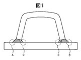
- FIG. 1 is a view showing an example of a welded joint and a welded structure.
- FIG. 1 is a schematic diagram for explaining a structure when a member having a U-shaped cross section is attached to a flat plate by welding to ensure bending rigidity.
- FIG. 1 In the case of the example shown in FIG. 1, the U-shaped member is welded to the flat plate at two locations, and the joint is a T-shaped joint. At this time, since fatigue cracks occur in the stress concentration portion, they occur in the four locations indicated by reference signs A to D in the example shown in FIG.
- the two locations indicated by reference signs A and B are located outside the welded structure, so that it is easy to carry out repairs, and the shape of the weld toe is processed smoothly in advance. It is possible to improve the fatigue strength by performing a peening process and applying compressive residual stress.
- the two weld toes indicated by reference characters C and D in FIG. 1 are structurally sealed and cannot be post-processed after the end of welding.
- This is a very simple process in which, in the case of a mechanical post-processing method such as peening, the processing must be performed while directly contacting a portion where fatigue is a problem (see reference numerals C and D in FIG. 1).
- the fatigue strength of the welded structure as shown in FIG. 1 is determined by the fatigue strength of the weld toe indicated by symbols C and D, and the fatigue strength of the weld toe indicated by symbols A and B.
- the problem remains that the fatigue strength of the entire welded structure is not improved.
- the technique disclosed in the document only discloses a technique for a joint when the weld toe is located outside.
- the welding material disclosed in Patent Document 1 is not necessarily used. Not obvious.
- the welding of the T-joint is completed by two-pass welding, but in this case, the heat generated when forming the subsequent weld bead, that is, the outer weld bead, is generated by the inner bead. Since the residual stress is broken, the original effect cannot be obtained.
- the fatigue strength of a welded structure is a factor that determines the life of the entire welded structure, and in particular, the fatigue strength of the entire welded structure is determined at a portion where the fatigue strength is lowest.
- the present invention has been made in view of the above problems, and mechanical treatment such as shot peening is applied to the weld toe portion or root portion where fatigue strength is a problem due to the existence of a sealed region in structure.
- Another object of the present invention is to provide a method for manufacturing a welded joint capable of improving fatigue strength when measures for improving fatigue strength by welding such as bead formation cannot be taken.
- the present inventors are able to achieve the improvement of the fatigue strength of the welded joint when there is a weld toe portion or root portion having a structure that cannot take measures for improving the mechanical fatigue strength.
- This invention is made
- the multi-pass welding is performed such that the transformation start temperature of the weld metal in the first pass is in the range of 175 ° C to 400 ° C.
- a first welding step in which welding is performed using a material, and then welding in which the weld metal is raised in one or more passes so that a part of the weld metal formed in the first welding step becomes an unmelted portion.
- a second welding step for retransforming all the unmelted portions into austenite by the welding heat of the final pass.
- the multi-pass welding is performed such that the transformation start temperature of the weld metal in the first pass is in the range of 175 ° C to 400 ° C.
- a first welding process in which welding is performed using a material, and then the weld metal is raised in one or more passes so that a part of the weld metal formed in the first welding process becomes an unmelted portion.
- a method for manufacturing a welded joint comprising: a second welding step for performing welding, and then a heat treatment for retransforming all the unmelted portions into austenite.
- the weld joint is a T joint, and the joint portion of the T joint is composed of an unwelded portion and welded portions on both sides sandwiching the unwelded portion, and the welded portion is subjected to multi-pass welding by partial melting welding only from one side.
- a method for manufacturing a joint is a cruciform joint, and a joint portion of the cruciform joint is composed of an unwelded portion and welded portions on both sides sandwiching the unwelded portion, and the welded portion is subjected to multi-pass welding by partial melting welding only from one side.
- the length of the unwelded portion existing between the multipass welds and the minimum thickness of the steel plate forming the T joint are the A method for manufacturing a welded joint, characterized in that it is at least three times the maximum thickness of each pass weld bead in pass welding.
- the weld joint is a T joint or a cross joint, and a joint portion of the weld joint includes an unwelded portion and welded portions on both sides sandwiching the unwelded portion, and the welded portion is subjected to partial melting welding only from one side.
- any one of (1) to (11) is characterized in that post-processing is performed by grinder processing on the toe portion of the weld bead on the welding side.
- a method for producing a welded joint according to claim 1. Any one of (1) to (11) is characterized in that after the second welding step, post-treatment by peening treatment is performed on the toe portion of the weld bead on the welding side.
- a method for producing a welded joint according to claim 1. (14) After the second welding step, the toe portion of the weld bead on the welded side is subjected to a reheating treatment with a TIG arc, (1) to (11) The manufacturing method of the welded joint in any one.
- a welded joint of the present invention there is an inner weld toe or root portion having a structure that cannot be post-processed mechanically or by welding due to the structure of the welded joint or the structure of the welded structure. Even in this case, the fatigue strength of the welded joint can be improved, the life of the entire welded structure can be improved, or the existing welded structure can be repaired to prolong the life of the welded structure.
- the industrial significance is extremely large.
- FIG. 1 It is a schematic diagram for demonstrating an example of the manufacturing method of the welded joint of this invention, and is a partial expanded sectional view which shows the weld part of the welded joint shown in FIG.
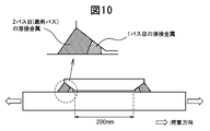
- FIG. 1 It is a schematic diagram for demonstrating the Example of the manufacturing method of the welded joint of this invention, and is sectional drawing which shows the load direction at the time of conducting the fatigue test in Example 1.
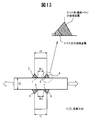
- FIG. 1 It is a schematic diagram for demonstrating the Example of the manufacturing method of the welded joint of this invention, and is sectional drawing which shows the load load direction at the time of conducting the fatigue test in Example 3.
- FIG. It is a schematic diagram for demonstrating the welded joint of this invention, and is the elements on larger scale which show the weld part of the square joint in Example 5.
- FIG. 1 It is a schematic diagram for demonstrating the Example of the manufacturing method of the welded joint of this invention, and is sectional drawing which shows the load loading direction at the time of conducting the fatigue test of the corner joint in Example 5.
- FIG. It is a schematic diagram for demonstrating the Example of the manufacturing method of the welded joint of this invention, and is sectional drawing which shows the load load direction at the time of conducting the fatigue test of the lap joint in Example 5.
- FIG. It is a schematic diagram for demonstrating the Example of the manufacturing method of the welded joint of this invention, and is sectional drawing which shows the load load direction at the time of conducting the fatigue test of the T joint in Example 5.
- FIG. 1 It is a schematic diagram for demonstrating the Example of the manufacturing method of the welded joint of this invention, and is sectional drawing which shows the load load direction at the time of conducting the fatigue test of the T joint welded from both sides in Example 6.
- FIG. It is a schematic diagram for demonstrating the Example of the manufacturing method of the welded joint of this invention, and is sectional drawing which shows the load direction at the time of conducting the fatigue test of the cross joint in Example 6.
- FIGS. 1 to 13 an embodiment of a method for manufacturing a welded joint according to the present invention will be described with reference to FIGS. 1 to 13 as appropriate.
- this embodiment is described in detail in order to make the purpose of the manufacturing method of the welded joint of the present invention better understood, the present invention is not limited unless otherwise specified.
- the fatigue strength improving methods are roughly divided into three types.
- the first is a method of applying mechanical or mechanical treatment such as impact to the surface, such as shot peening
- the second is to adjust the composition of the weld metal and use the transformation expansion of the weld metal.
- a method of adding ingenuity to material characteristics such as components of steel or welding material
- the third is a method of applying heat after welding.
- these methods will be called a mechanical method, a material method, and a heat treatment method, respectively.
- the present invention can be said to be a method using both a materialistic method and a heat treatment method.
- the present invention aims to improve the fatigue strength of a welded joint having a structure in which a fatigue strength improving method such as mechanical treatment cannot be performed.
- a structure has a partially sealed structure as a welded structure, or as a welded joint, there is an unwelded part such as a partial penetration, so that direct peening treatment or Indicates a case where grinder processing cannot be performed.
- a low-temperature transformation melt such a component-based welding material
- the weld metal formed at that time is called a low-temperature transformation weld metal.
- the low-temperature transformation melt contains a large amount of Ni, Cr, etc., and is also a component system that easily generates hot cracks. In such a case, depending on the shape of the joint, if one-pass welding is performed, butt solidification is likely to occur in the weld metal, and the risk of causing hot cracking is extremely high.
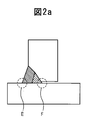
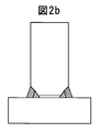
- Such joints that cannot take measures to improve fatigue strength by mechanical treatment, etc., include a case where a sealed space exists as shown in FIG. 1 as well as a partial penetration as shown in FIG. 2a.
- a sealed space exists as shown in FIG. 1 as well as a partial penetration as shown in FIG. 2a.
- a welded joint by welding since there is an unwelded portion even if there is no sealed space, it is directly mechanically applied to a stress concentration portion (see the portion indicated by symbol F in FIG. 2a) where fatigue becomes a problem.
- processing cannot be performed As shown in FIG. 1, when a mechanical treatment cannot be performed due to the presence of a sealed space, the locations indicated by reference characters C and D in FIG. 1 are called inner weld toes and are shown in FIG. 2a.
- a case where an unwelded portion exists is referred to as a root portion.
- the above-described fatigue strength problem of the inner weld toe portion 21 and the root portion 41 on the sealed space side is solved as follows.
- two methods are disclosed: a case where heat treatment is not performed after welding (see claim 1) and a case where heat treatment is performed (see claim 2).
- the former is referred to as a non-heat treatment type, and the latter is referred to as a heat treatment type.
- the method for manufacturing a non-heat treatment type welded joint includes a steel material 11 (of the welded joint 10 (30) in terms of the structure of the welded joint or the welded structure. 31) is a structure that can be welded only from one side, and the inner weld toe portion 21 covered with the welded structure 1 or the route portion 41, which is formed by partial penetration welding and cannot be accessed from the outside, is mechanical. Or it is a method of manufacturing a welded joint 10 (30) having a structure that cannot be post-processed by welding.
- the insoluble Second which introduces compressive residual stress to the inner weld toe portion 21 or the root portion 41 by performing welding that heats up the weld metal in one pass with welding heat input that is heated until the melted portion is retransformed into austenite. And a welding process.
- a weld bead inner weld toe, Root part
- This weld metal is a low-temperature transformation weld metal.
- a second weld bead (outer weld toe) is formed as a subsequent bead. This corresponds to the second welding process.
- a melt suitable for the strength of the steel plate forming the welded structure that is, a normal welding material, or a low-temperature transformation melt.
- a normal welding material for forming the second bead from the viewpoint of selecting a material having low hot cracking sensitivity.
- the weld joint is formed by two-pass welding, but simply by performing two-pass welding, the compressive residual stress formed by the first weld bead due to the low-temperature transformation melt disappears by the second bead. There is a danger that the fatigue strength will not improve. Therefore, when the second welding process is performed, it is necessary to generate the compressive residual stress again after the initially formed compressive residual stress disappears.
- the technical idea that forms the basis of the present invention is that the compressive residual stress is again generated by the second weld bead. That is, the compressive residual stress that improves the fatigue strength is not a residual stress that occurs when welding using a low-temperature transformation melt, but a residual stress that occurs when the second welding is performed.
- a low temperature transformation material in the prior art is a technology that introduces compressive residual stress by utilizing transformation expansion, and this compressive residual stress is generated in the cooling process during welding using the low temperature transformation material.
- this compressive residual stress corresponds to the compressive residual stress generated in the first-pass welding, but in the present invention, this compressive residual stress disappears in the second welding.
- the technical idea forming the basis of the present invention is to generate compressive residual stress again at the second welding, and further, the welding material used for the second welding is not necessarily limited to the low-temperature transformation melt.
- the untransformed part is only thermally contracted during the subsequent cooling and does not undergo transformation expansion. Sufficient compressive residual stress cannot be generated again. Further, even if welding is performed so as to simply cover the surface of the low temperature transformation weld metal formed by the first welding, the low temperature transformation weld metal formed by the first welding cannot be retransformed into austenite.
- part or all of the low temperature transformation weld metal formed in the first welding process needs to be unmelted. If all the low temperature transformation weld metal is melted in the second welding, the compressive residual stress is not reintroduced. On the other hand, in the final welding pass in the second welding process, all of the unmelted low temperature transformation weld metal must be heated before retransformation to austenite. It is not particularly difficult to examine such conditions in advance if it is a person concerned with welding. Prepare a specimen having the same shape as the actual weld joint in advance, and perform the first welding process and the second weld process with the same welding material as the welding material to be used when actually welding.
- the unmelted low temperature This is because whether or not all of the transformation weld metal has retransformed to austenite can be easily determined by observing the structure of the cross-sectional macro.
- the welding conditions may be determined in advance, and welding may be performed on the actual welded joints under these conditions.
- the transformation start temperature of the low temperature transformation weld metal can also be confirmed by collecting a test piece from the unmelted low temperature transformation weld metal portion of the weld joint prepared in advance and measuring the transformation start temperature.
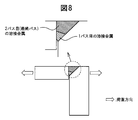
- the joint is a joint called a T joint, but the present invention aims to improve the fatigue strength by controlling the residual stress. If the effect is negligible, it is considered that there are two welds that are welded only from one side. In this case, the unwelded portion corresponds to a sealed space sandwiched between the welds on both sides. The fact that it is far enough not to affect the residual stress also depends on the welding heat input. When the heat input amount is high, the thickness of the weld metal formed in the welding pass at that time also increases. Therefore, in the present invention, the thickness of the weld metal is employed instead of the heat input amount. In the present invention, the thickness of the weld metal is defined as shown in FIG.
- one point A on the surface of the weld metal is determined.
- a tangent of the weld metal surface at A is determined, and then a straight line that intersects the tangent perpendicularly and passes through the point A is obtained.
- the intersection of this straight line and the fusion line of the weld metal is defined as B, and the distance between point A and point B is defined as the thickness at point A.
- the thickness is defined at each point of the weld metal, and the maximum value is determined as the thickness of the weld metal.
- the weld metal surface disappears. Therefore, it is necessary to determine the thickness after each welding pass and before the subsequent welding pass is performed. It is necessary to pay attention to.
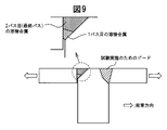
- the maximum value is compared with the length of the unwelded part, and when the length of the unwelded part is more than three times the maximum value, It has been found that the existing weld metals can be regarded as independent of each other and do not affect the residual stress. When the unwelded portion is shorter than this, the welding process on one side affects the residual stress on the other side, and the fatigue strength may not always improve, so this value was set.
- the cross joint it can be considered that a T-joint welded from both sides is formed on each of the front side and the back side of one steel plate.
- the limiting conditions for forming the respective T joints must satisfy the limiting conditions set when forming the T joints.
- the cross joint in addition to this condition, it is necessary to pay attention to the welding heat transmitted through the steel plate. In this case, it is sufficient that the plate thickness is thick enough not to affect the residual stress.
- the unwelded portion and the minimum thickness of the steel plate forming the cross joint are more than three times the maximum thickness of the weld metal formed in each welding pass, the newly formed weld metal was found to be independent of each other and not to affect the residual stress.
- the unwelded portion is shorter than this, the welding process on one side affects the residual stress on the other side, and the fatigue strength may not always improve, so this value was set.
- the above is the technical idea of the present invention in the non-heat treatment type fatigue strength improving method.
- the transformation of the above-mentioned low temperature transformation weld metal is not necessarily limited to a specific transformation as long as it is a volume expansion transformation that occurs at a low temperature defined by the present invention, but is generally within the temperature range of the present invention.
- the transformation that occurs in is the martensitic transformation.
- the martensitic transformation start temperature is characterized by being determined only by the weld metal component without depending on the cooling rate during welding.
- the estimation formula using a component is also known, for example, the following estimation formula is proposed.
- Ms 719-795C-20Cr-32Ni-35.6Si-13.3Mn-23.7Mo-11.9Nb
- Ms is the martensitic transformation start temperature (° C.), and C and the like indicate weld metal component values (mass%).
- the existence of such an estimation formula is a convenient index that can be a guide for material development for welding engineers. It should be noted that the transformation that occurs in the temperature range of the present invention is mainly the martensitic transformation in the heat treatment type described below.
- the manufacturing method of the heat treatment type welded joint in the present invention is the method of manufacturing the welded joint 10 (30) having the structure of a welded joint or a welded structure as described above.
- a first welding step for performing welding in which the root portion 41 is formed using a weld metal having a transformation start temperature in the range of 175 ° C. to 400 ° C., and an inner weld toe portion formed in the first welding step A second welding process in which welding is performed to raise the weld metal in one or more passes so that at least a part of the weld metal forming 21 or the root part 41 becomes an unmelted part, and then the first welding process.
- the low temperature transformation weld metal formed in the first welding step is heated by the second welding step until all of the low temperature transformation weld metal is retransformed into austenite.
- heat treatment is performed after welding, and this heat ensures that all of the low temperature transformation weld metal parts are This is a method of retransformation to austenite. Therefore, compared with the non-heat treatment type, the first welding process is the same as the heat treatment type, and as the second welding process, a part of the low temperature transformation weld metal formed in the first welding process is unmelted.
- the welding material does not necessarily need to use a low-temperature transformation melt.
- all or part of the low temperature transformation weld metal unmelted portion formed in the first welding process is not necessarily austenite in the final welding pass of the second welding process.
- the welded joint thus prepared is then processed in a heat treatment step, and then a cross-sectional macro is taken from the welded joint to determine whether there is an unmelted portion of the low temperature transformation weld metal, Whether or not all of the unmelted low-temperature transformation weld metal has been retransformed into austenite by heat treatment may be determined from the observation of the structure of the cross-sectional macro. In this way, welding conditions and heat treatment conditions are determined in advance, and an actual welded joint may be constructed under these conditions.
- the transformation start temperature of the low temperature transformation weld metal can also be confirmed by collecting a test piece from an unmelted low temperature transformation weld metal portion of a weld joint prepared in advance and measuring the transformation start temperature.
- the second welding process has two or more passes in the non-heat treatment type
- the final pass of the second welding step is separated from the weld metal formed in the first welding step, so It is desirable to limit the welding process 2 to the case of 1-pass welding.
- transformation start temperature of weld metal used in the first welding process First, the reason for limiting the transformation start temperature of the low temperature transformation weld metal will be described.
- fatigue is a problem, and a low temperature transformation weld metal is formed at the inner weld toe or root portion where fatigue strength improvement measures cannot be implemented by mechanical or welding post-treatment, and the transformation expansion of the low temperature transformation weld metal
- compressive residual stress is introduced into the weld toe or root.
- the upper limit of the transformation start temperature 400 ° C., was set at a transformation start temperature higher than this, because the thermal shrinkage after the end of transformation increased and the compressive stress introduced during transformation expansion disappeared.
- the lower limit of 175 ° C. has almost the same effect even when the transformation start temperature is lower than this, and in order to obtain a transformation start temperature lower than 175 ° C., This value was set because an alloying element material exceeding the limited range must be added, and the cost of welding material production and the risk of hot cracking increase.
- Heat treatment method in heat treatment process Next, a heat treatment method in the heat treatment mold will be described.
- a method for heat-treating the welded joint a method such as heating with a gas burner, energization heating with an electric heater, or putting the entire structure into a heat treatment path can be considered.
- a heat treatment method by electric heating or induction heating is preferred. Electric heating or induction heating and heating by a gas burner or an electric heater are greatly different in the following points.
- Electric heating is a method in which an electric current is passed through a welded joint and heated using Joule heat generated at that time.
- Induction heating is a method in which an eddy current is generated and heated using that. appear.
- heat is transferred from the joint surface to the inside of the joint by heat conduction.
- the subject of the present invention is the fatigue of the inner weld toe or root that cannot be post-processed mechanically or welded due to the structure, and therefore cannot be directly exposed with a gas burner or the like even when heat treatment is performed. . Therefore, in order to retransform low temperature transformation weld metal into austenite by heat treatment, it is necessary to continue heating until heat is conducted to the low temperature transformation weld metal.
- Ni-based components First, the reason for limiting the component range of Ni-based materials will be described.
- C carbon 0.01 to 0.15% C serves to lower the Ms temperature by adding it to iron.
- the upper limit was made 0.15%.
- C when C is not added, martensite is difficult to obtain, and the residual stress must be reduced only with other expensive elements, which is not economical.
- the reason for limiting the addition to 0.01% or more of C was to use C, which is an inexpensive element, and set it as the minimum value that would bring about its economic merit.
- the upper limit of C is more preferably set to 0.10% from the viewpoint of weld metal cracking.
- Si silicon 0.2-0.8% Si is known as a deoxidizing element. Si has the effect of lowering the oxygen level of the weld metal. Especially during welding, there is a risk of air being mixed during welding, so it is extremely important to control the amount of Si to an appropriate value.
- the lower limit of Si when the Si content is less than 0.2%, the Si content of the low-temperature transformation welding material is also low. In this case, there is a risk that the deoxidizing effect is weakened, the oxygen level in the weld metal becomes too high, and mechanical properties, particularly toughness, are deteriorated. Therefore, in the present invention, the lower limit is set to 0.2%. On the other hand, excessive addition of Si also causes toughness deterioration, so the upper limit was made 0.8%.
- Mn Manganese
- Ni is austenite by itself, that is, a metal having a face-centered structure, and is an element that makes the austenite state more stable when added to the weld metal.
- Iron itself has an austenite structure at high temperatures and a ferrite or body core structure at low temperatures.
- Ni is added, the face-centered structure in the high-temperature region of iron becomes a more stable structure, so that it becomes a face-centered structure even in a lower temperature region than in the case where Ni is not added. This means that the temperature at which it transforms into a body-centered structure is lowered.
- the lower limit of Ni of 7.0% was determined in the sense of the minimum addition amount at which the residual stress reduction effect appears.
- the upper limit of 11.5% of Ni does not change much in effect from the viewpoint of reducing residual stress, and in addition to adding more than this, there is an economic disadvantage that Ni is expensive. This is because there is a risk of hot cracking.
- the lower limit of Ni is more preferably set to 8.0% in order to surely improve the fatigue strength. The above is the reason for limitation to the Ni-based essential components in the present invention.
- group other than the said essential component the following components can be selectively added as needed.
- Cu Copper
- Cu Copper
- 0.05-0.4% Cu is an effective element for improving welding workability because, when the welding material is a wire, it has the effect of improving the electrical conductivity by plating on the wire.
- excessive addition is not preferable in the industry because the effect of improving workability is saturated, and further, the wire manufacturing cost is increased.
- the upper limit of Cu of 0.4% is set for this reason.
- the lower limit of 0.05% of Cu was set as a minimum value at which the effect of improving the electrical conductivity was obtained.
- Nb niobium
- Nb carbide works to increase the strength of the base metal and the weld metal in a small amount, and therefore, the economic merit of effective use is great.
- the lower limit of Nb was set to 0.005% as the lowest value at which carbides can be formed and an effect of increasing strength can be expected.
- the upper limit of Nb is set to 0.1% because the effect of increasing the strength is saturated even if the problem of weld cracking due to a significant increase in strength and the problem of weld cracking can be avoided.
- V Vanadium
- V Vanadium
- Nb vanadium
- the lower limit of 0.01% for V addition is set as the lowest value at which precipitation hardening can be expected by addition.
- the upper limit of V is added more than this, precipitation hardening becomes too remarkable, and even if excessive addition is carried out, the improvement is saturated from the viewpoint of fatigue improvement effect, and further, excessive precipitation hardening is caused. Therefore, the problem of weld cracking occurs, so 0.5% was set.
- Ti Titanium 0.005 to 0.1% Ti, like Nb and V, forms carbides and causes precipitation hardening.
- the precipitation hardening of V is different from that of Nb
- the precipitation hardening of Ti is also different from Nb and V. Therefore, the range of the addition amount of Ti is also set to a range different from Nb and V.
- the lower limit of Ti addition amount of 0.005% is the minimum amount at which the effect can be expected, and the upper limit of Ti of 0.1% is excessively added, the fatigue strength improving effect is saturated, and excessively Since the problem of cracking also occurs due to the precipitation effect, this value was set.
- Cr chrome 0.1-3.0% Cr is a precipitation hardening element like Nb, V, and Ti.
- Cr has an effect of reducing the Ms temperature, and is therefore an element that should be used effectively.
- the Cr addition amount should be less than that of Ni. Excessive Cr addition does not necessarily improve the residual stress reduction effect and is not industrially preferable because Cr is expensive.
- the lower limit of 0.1% of the Cr addition amount was set as a minimum value at which the residual stress reduction effect was obtained by adding this.
- the upper limit of the Cr addition amount is 3.0% for the Ni type because the Ms temperature has already been reduced by the addition of Ni and the strength is secured by other precipitation elements. However, the residual stress reduction effect is not changed so much.
- Mo Molybdenum 0.1-2.0%
- Mo is an element having the same effect as Cr.
- Mo is an element for which precipitation hardening can be expected more than Cr. Therefore, the addition range was set narrower than Cr.
- the lower limit of 0.1% was set as the minimum value at which the effect of Mo addition can be expected.
- 2.0% of the upper limit of Mo was set because the fatigue strength improvement allowance would be saturated even if added more than this.
- group since the transformation start temperature is mainly achieved by Ni, it is desirable to set the minimum of the transformation start temperature of Ni type
- Si silicon 0.1-0.7% Si is known as a deoxidizing element.
- Si silicon
- the lower limit of Si when the amount of Si in the low temperature transformation weld metal is less than 0.1%, it means that the amount of Si in the low temperature transformation welding material is also low, and the deoxidation effect is diminished and the low temperature transformation. There is a risk that the oxygen level in the weld metal becomes too high, leading to degradation of mechanical properties, especially toughness. Therefore, the lower limit of the Si content of the low temperature transformation weld metal is set to 0.1%.
- the lower limit of Si is more preferably 0.30%. On the other hand, even if Si addition exceeding 0.7% is performed, the workability improvement effect is saturated, so the upper limit was made 0.7%.
- Mn Manganese 0.1-2.0%
- Mn is used as an element for increasing the strength, but in the Cr—Ni system in the present invention, the effect has already been obtained by Cr or the like. Therefore, the addition of Mn is mainly aimed at the deoxidation effect as in Si.
- the lower limit of 0.1% of Mn was set as the minimum value at which a deoxidizing effect was obtained.
- the upper limit of 2.0% was set to 2.0% because the deoxidation effect allowance would be saturated even if more additions were made.
- Ni nickel 4.0-8.0%
- Ni is a single austenite, that is, a metal having a face-centered structure. Iron itself has an austenite structure at a high temperature range and ferrite, that is, a body-centered structure at a low temperature range. When Ni is added, the face-centered structure in the high-temperature region of iron becomes a more stable structure, so that it becomes a face-centered structure even in a lower temperature region than in the case where Ni is not added. This means that the temperature at which it transforms into a body-centered structure is lowered. Moreover, Ni has the effect of improving the toughness of the weld metal by adding it.
- the lower limit of 4.0% of the addition amount of Ni in the Cr-Ni low temperature transformation weld metal was determined from the viewpoint of securing the minimum addition amount and toughness in which the residual stress reduction effect appears.
- the upper limit of the Ni addition amount is 8.0% in the case of Cr-based welding wires, since the Ms temperature is reduced to some extent by the addition of Cr described below, and from the viewpoint of reducing residual stress, the upper limit of Ni addition amount is However, the effect is not changed so much, and if it is added more than this, an economic demerit that Ni is expensive is caused, so this value was set.
- Cr Chromium
- Cr Chromium
- the upper limit of 15.0% of Cr is that when the amount exceeding this is added, the transformation temperature becomes too low and the transformation expansion amount becomes small, so that the effect of improving fatigue strength tends to decrease.
- the above is the reason for limiting the Cr—Ni-based essential components in the present invention.
- the following elements can be selectively added to the Cr—Ni system in the present invention.
- the purpose of adding the following components is not necessarily intended to improve the fatigue strength, but whether or not to add can be easily determined by those involved in welding.
- Cu Copper
- 0.05-0.4% Cu is an effective element for improving welding workability because it has the effect of improving the conductivity by plating on the low-temperature transformation welding material when it is a wire.
- the lower limit of 0.05% of Cu is that the amount of Cu plated on the wire is also lower when the Cu in the low temperature transformation weld metal is lower than this.
- the limit value was set.
- excessive addition of Cu not only has an effect of improving workability but also increases the wire manufacturing cost, which is not preferable from an industrial viewpoint.
- the upper limit of Cu of 0.4% is set for this reason.
- Nb niobium
- Nb carbide works to increase the strength of the weld metal in a small amount, and therefore, the economic merit of effective use is great.
- excessive carbide formation has an excessively high strength and causes a problem of weld cracking and deterioration of toughness.
- the lower limit of Nb was set to 0.005% as the lowest value at which carbides can be formed and an effect of increasing strength can be expected.
- the upper limit of Nb is set to 0.1% as a value that prevents the problem of cracking and does not impair the reliability of the weld due to toughness deterioration.
- V Vanadium
- V Vanadium
- the lower limit of V addition of 0.01% was set as the lowest value at which precipitation hardening can be expected by addition.
- the reason for setting the upper limit of V is the same as in the case of Nb, and if added more than this, precipitation hardening becomes excessively significant, causing toughness deterioration, and from the viewpoint of causing weld cracking due to excessive hardening, the upper limit is set to 0. 0.5%.
- Ti Titanium 0.005 to 0.1% Ti, like Nb and V, forms carbides and causes precipitation hardening.
- the range of the addition amount of Ti is also set to a range different from Nb and V.
- the lower limit of 0.005% of the Ti addition amount is determined as the minimum amount at which the effect can be expected, and the upper limit of 0.1% is determined from the viewpoint of preventing toughness deterioration and excessive weld cracking due to steel.
- Mo Molybdenum 0.1-2.0% Mo is also an element that can be expected to precipitate and harden like Nb, V, and Ti. However, Mo needs to be added more than Nb, V, Ti in order to obtain the same effect as Nb, V, Ti.
- the lower limit of 0.1% of the Mo addition amount was set as the minimum value at which an increase in yield strength due to precipitation hardening can be expected. Further, 2.0% of the upper limit of Mo is set to this value because the fatigue strength improvement allowance is saturated even if it is added more than this.
- the present invention relates to a method for improving the fatigue strength of the inner weld toe portion or the root portion where measures for improving the fatigue strength by mechanical treatment or the like cannot be implemented. Therefore, the weld toe portion on the side where welding is performed is not necessarily an object of the present invention. However, when a fatigue crack can improve the fatigue strength of one part, the fatigue strength of another part will determine the fatigue strength of the whole joint. Therefore, the inventors further improve the fatigue strength of the inner weld toe portion or the root portion on the side where the fatigue strength improvement measures cannot be implemented by mechanical or welding post-processing, and then further increase the fatigue strength of the opposite side. It was considered industrially significant to provide measures to improve the fatigue strength of parts.
- Measures to improve fatigue strength can be broadly divided into methods that reduce residual stress and methods that relieve stress concentration.
- a method for reducing the residual stress there is a method in which the entire structure is uniformly heated and then gradually cooled.
- the compressive residual stress introduced by the low-temperature transformation weld metal is lost, so even if it is a measure for improving fatigue strength, it cannot be applied without limitation.
- one or both of the outer weld toe portions 22 (42) on both sides of the weld bead on the welding side formed in the second welding step reference numerals 22a and 22b in FIGS. 1 and 2). , 42a and 42b), the shape of the outer weld toe 22 (42) subjected to the post-processing is smoother than that of the as-welded state by performing post-processing by machining such as grinder processing. It can be set as the method of performing the mechanical post-processing processed into.
- the method in which the weld toe is machined more smoothly than in the as-welded state is a method that relieves stress concentration, and does not significantly affect the residual stress introduced by the low-temperature transformation weld metal. Therefore, it is a preferable method as a fatigue strength improving method applied to the joint targeted by the present invention.
- post-processing by peening such as shot peening, ultrasonic peening, air peening, or the like on one or both of the outer weld toe portions 22 (42) on both sides of the weld bead on the side where welding is performed.
- peening such as shot peening, ultrasonic peening, air peening, or the like
- the shape of the outer weld toe portion 22 (42) subjected to the post-processing is processed more smoothly than the as-welded state, and the compressive residual stress is applied to the outer weld toe portion 22 (42).
- This can be a method of performing mechanical post-processing.
- Fatigue strength improvement measures by post-processing of peening treatment such as ultrasonic peening introduces compressive residual stress to the treated part in addition to the effect of relieving stress concentration. Bigger than the case. Further, since it does not significantly affect the residual stress introduced by the low temperature transformation weld metal, it is a preferable method as a fatigue strength improving method applied to the joint targeted by the present invention.
- this TIG welding is performed by performing TIG welding (TIG tanning welding) which does not use a filler material with respect to one or both of the outer weld toe portions 22 (42) on both sides of the weld bead. It can be set as the method of performing the post-process by welding which processes the shape of the outer side weld toe part 22 (42) which gave smooth rather than the state as-welded.
- TIG welding TIG tanning welding
- TIG tanning welding is a method of relieving the stress concentration at the weld toe, etc. by remelting the joint surface with welding arc heat without using a welding material.
- the method of applying heat to a welded joint requires caution in its use because it may eliminate the compressive residual stress introduced by the low temperature transformation weld metal.
- TIG tanning welding is preferable because it can achieve sufficient stress relaxation with a small heat input even if it is a method of applying heat, so that it can be applied to the joint targeted by the present invention. Is the method.
- welding in which one or both of the outer weld toe portions 22 (42) on both sides of the weld bead have the same component and transformation start temperature as the weld metal used in the first welding step.
- a post-process for forming a weld bead (decorative bead) that is a metal a post-process by welding is performed to introduce compressive residual stress to the outer weld toe 22 (42) subjected to the post-process.
- the method can be adopted.
- the method of forming a decorative bead on the weld toe portion on the side where welding is performed using the same welding material as that used to form the low-temperature transformation weld metal in the first welding process has a small amount of welding and a welded joint.
- This is a preferable method that can be applied to the joint that is the subject of the present invention.
- this method is a method for controlling the residual stress.
- the TIG tanning welding method for applying the same heat to the joint is a method for reducing the stress concentration, and the method for improving the fatigue strength is different.
- the TIG tanning welding method can be performed either before or after the heat treatment, but the method of forming the decorative bead needs to be performed after the heat treatment. is there. This is because if the cosmetic bead is formed before the heat treatment, the compressive residual stress formed by the cosmetic bead during the heat treatment disappears. If the decorative bead is formed before the heat treatment, it is necessary to set heat treatment conditions so that both the low temperature transformation weld metal formed during the first welding process and the weld metal of the decorative bead are retransformed to austenite. However, in this case, since the heating width becomes wide, the residual stress due to heat treatment and the risk of introducing deformation increase. Therefore, in the present invention, when adopting the heat treatment type fatigue strength improving method, it is desirable that the decorative bead is carried out after the heat treatment.
- the welded joint manufacturing method of the present invention direct mechanical processing of a structure that cannot be mechanically or post-processed by welding due to structural problems of the welded joint or the structure of the welded structure. Even if there is an inner weld toe or root that cannot be performed, the fatigue strength of the welded joint can be improved, the life of the entire welded structure can be improved, or the existing welded structure Can extend the life of the welded structure by repairing it, and it has great industrial significance.
- Example 1 is an example of a non-heating type fatigue strength improvement measure.
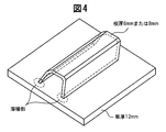
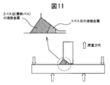
- a structure as shown in FIG. 4 was assembled by welding. The state of the welded portion at that time was as shown in FIG.
- the upper plate thickness in FIG. 4 was set to 6 mm.
- various welding materials were made as prototypes.
- SMAW manual welding
- GMAW carbon dioxide gas welding
- the amount of heat input was changed.
- the amount of heat input is described for the second pass SMAW.
- the second-pass welding material there are a case where the same welding material as that in the first pass is used and a case where a normal welding material, that is, a welding material having a strength level in the range of 490 MPa to 780 MPa is selected. In either case, the above conditions were adopted as the welding conditions.
- the welding conditions are limited to the above welding conditions. is not.
- the normal welding material the following components (welded metal components) were used.
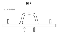
- FIG. 6 is a schematic diagram showing a load application direction when a fatigue test is performed, and an arrow in FIG. 6 indicates a load application direction.
- the fatigue test was performed by a four-point bending test, and the fatigue load was measured by attaching a strain gauge to the inner weld toe of the weld metal formed in the first welding process. Note that the strain gauge was able to be attached because it was a specimen, and it is considered difficult to measure stress with the strain gauge in the case of an actual welded structure.
- Table 1 below shows the measurement results of the components and transformation start temperatures of the weld metal formed in the first welding process.
- the weld metal component was measured by collecting a specimen for component analysis directly from the formed weld metal after welding.
- the transformation start temperature is the result of measuring the transformation start temperature by taking a formaster test from the weld metal formed after welding. That is, a round bar-shaped test piece was collected from the weld metal, heated and cooled, and the length of the test piece at each temperature was measured to measure the expansion and contraction of the weld metal, thereby determining the transformation start temperature.
- numbers 1 to 14 indicate that the weld metal component and the transformation start temperature are within the scope of the present invention.
- the present invention relates to a method for improving fatigue strength
- the present invention is not necessarily an example of the present invention if the weld metal component and the transformation start temperature are within the scope of the present invention.
- the components and transformation start temperatures within the scope of the present invention are described as examples of the present invention.
- the components of the weld metal shown in Table 1 below are examples of Ni-based components in the present invention.
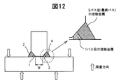
- Table 2 the components of the weld metal formed in the first welding step when a test body as shown in FIG. 4 was produced with a welded joint as shown in FIG.
- the transformation start temperature was indicated. 4 and 5, welded joints exist on the left and right, but the joints were produced under the same welding conditions.
- numbers 101 to 116 are weld metals within the scope of the present invention.
- the weld metal component and the transformation start temperature are It is not necessarily the case of the present invention that is within the scope of the present invention.
- the components and transformation start temperatures within the scope of the present invention are also described as examples of the present invention.
- Numbers 151 to 162 are comparative examples in the present invention. Among these, numbers 152, 155, 160, 161, and 162 are examples in which cracks and defects occurred in the weld metal, and the transformation start temperature was measured by selecting a weld metal portion in which no cracks occurred. In other comparative examples, cracks and the like are not generated, but since the composition of the weld metal is outside the scope of the present invention, the transformation start temperature is outside the scope of the present invention.
- Table 3 below shows the fatigue strength when the component type weld metals shown in Tables 1 and 2 are formed in the first welding step and a fatigue load as shown in FIG. 6 is applied.
- the fatigue strength at this time was determined as a stress range that does not break even when fatigue load was applied 2 million times.
- the stress range is a value measured by attaching a strain gauge to the test body before the fatigue test is performed in the vicinity of the weld metal side formed by the first-pass welding.
- the fatigue strength of 200 MPa means that the stress range was 0 to 200 MPa, and it did not break even after repeated loading 2 million times.
- SMAW manual welding method
- GMAW gas shield welding method
- [1] means the first welding process
- [2] means the second welding process.
- the components of the weld metal formed in the first welding process are those in Tables 1 and 2, and the weld metal numbers ([1] weld metal numbers) for the respective joints are shown in Table 3 below.
- the same welding material as that in the first welding process is not necessarily used, and a normal 590 MPa class welding material may be used.
- the welding materials (welding materials [2]) used in the second welding step for each joint are also shown in Table 3 below.
- Table 3 also shows the results of whether or not the weld metal formed in the first welding process has been retransformed to austenite by macro test observation.
- J1 to J36 in Table 3 indicate that the weld metal having the components and the transformation start temperature within the scope of the present invention is formed in the first welding step. It is a joint when it retransforms to austenite in the second welding process, and as can be seen from Table 3, the fatigue strengths all exceed 250 MPa.
- J33 to J36 are cases where the strength of the welding material used in the second welding process is different from that of J1 to J32, but because retransformation of the weld metal formed in the first welding process is achieved, It can be seen that the fatigue strength is improved.
- J101 to J111 are comparative examples, and since the transformation start temperature was outside the range of the present invention, the fatigue strength did not reach 250 MPa.
- J101, J103, J105, J108, and J109 are joints in which weld metals of numbers 53 and 55 in Table 1 and numbers 151, 156, and 157 in Table 2 are formed in the first welding process, and transformation starts.
- the temperature after the heating is lower than the range of the present invention.
- These joints are considered to be examples in which the effect of improving the fatigue strength is insufficient because the transformation start temperature is too low and a sufficient transformation expansion amount cannot be obtained.
- J102, J104, J106, J107, J110, and J111 are joints in which weld metals of numbers 54 and 58 in Table 1 and numbers 153, 154, 158, and 159 in Table 2 are formed by the first welding process.
- the transformation start temperature was higher than the range of the present invention and the residual stress reduction was insufficient.
- the four joints J112 to J115 have a second pass from the macro observation even though the transformation start temperature of the low temperature transformation weld metal formed in the first welding process is within the scope of the present invention. Since the heat input was small, it was found that the low temperature transformation weld metal was retransformed to austenite only in a part of the unmelted part in the second welding process. In this case, it is considered that the compressive residual stress introduced in the first welding process disappears and the compressive residual stress is not introduced again in the second welding process, so that the fatigue strength is not improved.
- the transformation start temperature was within the range of the present invention, but the amount of heat input in the second pass was inappropriate, and there was no unmelted portion of the weld metal formed in the first pass.
- the fatigue strength was not improved.
- the fatigue strength improvement effect was confirmed altogether and it became clear that it is industrially significant.
- Example 2 is an example relating to the heat treatment type fatigue strength improving method of the present invention.
- the heat treatment type method in this example in order to make the number of welding passes in the second welding process two, the upper plate thickness in FIG. Added pass welding.
- the total welding is a total of three passes, one pass in the first welding step and two passes in the second welding step.
- two types of induction heating and current heating were selected. Induction heating was performed at 2.0 kHz of 20 kW, and energization heating was performed by supplying a current of 250 A to the weld bead.
- Table 4 below shows the results of Example 2.
- the meanings of the welding materials [1] and [2], [1] weld metal number, and [2] of the welding method are the same as in Table 3.
- the determination of retransformation is a determination of whether or not retransformation was performed by heat treatment after the heat treatment.
- the fatigue test was implemented by the same method as Example 1, and let the stress range which was not fractured by 2 million times be the fatigue strength.
- the numbers from J201 to J230 are examples of the present invention when heat treatment was performed by induction heating using a 590 MPa class welding material in the second welding step, and the fatigue strengths all exceeded 250 MPa.
- J231 and J232 are examples of the present invention when the same welding material is used in the second welding process as in the first welding process, and it can be seen that there is an effect of improving fatigue strength.
- J232 to J235 are examples of the present invention in which electric heating is used for heat treatment, and an effect of improving fatigue strength is recognized.
- the weld metal formed in the first welding process is the same as J201, but the strength of the welding material used in the second welding process is 490 MPa and 780 MPa, which is different from J201.
- the fatigue strength exceeds 250 MPa, and this is an example in which the strength improvement effect has been confirmed.
- J301 to J315 in Table 4 are comparative examples in the present invention, and the fatigue strength does not reach 250 MPa, unlike the examples of the present invention.
- J301, J303, J305, J308, and J309 have a lower residual stress reduction because the transformation start temperature of the weld metal formed in the first welding process is lower than the range of the present invention and transformation expansion is insufficient. It is thought that it was not enough.
- J302, J304, J306, J307, J310, and J311 it is considered that the transformation start temperature of the weld metal formed in the first welding process is higher than the range of the present invention, and the residual stress reduction effect itself is small. .
- J312 to J315 have the transformation start temperature of the low temperature transformation weld metal within the range of the present invention, but the heat treatment was insufficient and only a part of the unmelted portion was retransformed to austenite. That was not possible.
- the last comparative example J316 in Table 4 is an example in which the weld metal in the first pass was completely melted by the weld in the second pass, and the unmelted portion disappeared. Therefore, the fatigue strength was not improved. It is an example. As mentioned above, in the case of this invention example, the fatigue strength improvement effect was confirmed altogether and it became clear that it is industrially significant.
- Example 3 in this invention is an example at the time of post-processing as a fatigue strength improvement measure to the outer side weld toe part of the weld metal formed at the 2nd welding process.
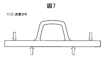
- Example 1 and Example 2 since the fatigue strength on the weld metal side formed in the first welding process was considered as a problem, the fatigue test was performed as shown in FIG. , And the difference was made in the stress at the weld metal toe portion formed in the first welding process and the second welding process.
- Example 3 in order to apply the same level of stress as shown in FIG. 7, the position of the inner two fulcrums in the four-point bending test was positioned outside the welded joint. The stress was measured by attaching a strain gauge.
- the arrow in FIG. 7 shows a load load direction.
- Fatigue strength improvement measures applied to the outer weld toe of the weld metal formed in the second welding process are shot peening, TIG tanning welding, ultrasonic peening, low temperature transformation weld metal formation, grinder processing, local heating It is either of stress relief by.
- the welding material used for forming the low temperature transformation weld metal was the same as the welding material used in the first welding process.
- shot peening, ultrasonic peening, and low temperature transformation weld metal formation are methods for introducing compressive residual stress, and among these, the two further have the effect of improving the toe shape.
- TIG tanning welding and grinder processing are methods for improving the toe shape and reducing stress concentration.
- the final stress removal by local heating is a method of eliminating the tensile residual stress of the welded portion, but at the same time, there is a risk of eliminating the compressive residual stress introduced in the first welding process. is there.
- Table 5 below shows the results of Example 3.
- the joint numbers in Table 5 below correspond to the joint numbers in Table 3, which means that measures for improving fatigue strength were applied to the outer weld toes on the second welding process side.
- the processing method shown in the following Table 5 is a countermeasure method for improving fatigue strength at that time.
- [1] means that a fatigue crack has occurred at the inner weld toe on the first welding process side, and [2] 2 occurred at the outer welding toe on the welding process side.
- K1 to K5 and K101 to K105 are examples of the present invention, and K51 and K151 are comparative examples.
- K1 had a fatigue strength of 290 MPa, almost the same value as J1 in Table 3, and the crack generation position was [1]. This is considered that the fatigue strength of [2] became higher than [1] by shot peening.
- a similar tendency is observed for the numbers K3 and K4.
- K2 and K5 fatigue cracks occurred in [2] and the fatigue strength is considered to be lower in [2] than in [1]. Since these are almost the same as J1, in these cases, [1] and [2] are considered to have almost the same fatigue strength.
- a similar tendency is observed for K101 to K105.
- K51 and K151 are stress relief by local heating, that is, SR, and the heating method is heating using a gas burner.
- the fatigue strength does not reach 250 MPa.
- fatigue cracks occurred on the [1] side, that is, from the inner weld toe where the low temperature transformation weld metal was formed. In this example, it is lower than the fatigue strength of Table 3 shown in Example 1 (280 MPa for the J1 joint and 350 MPa for the J28 joint). The reason for this is considered that the compressive residual stress introduced to the first welding process side by local heating has disappeared by local heating.
- Example 4 is an example of measures for improving the fatigue strength of the non-heating type, but the point different from Example 1 is an example when the number of welding passes is 3 or more.
- SMAW was adopted as the welding method.
- the preparation of the test body at that time was the same as in Example 2, and the structure shown in FIG. 4 was adopted.
- the upper plate thickness was 8 mm, the same as in Example 2.
- the first two-pass welding was performed using a 3.2 mm diameter welding rod, and the component values of the weld metal at that time are as shown in Table 6.
- Table 6 four types of two-pass welding were performed.
- the welding conditions are 120A-22V-25 cm / min for each pass.
- a third pass of welding was performed on these four types of joints.
- the welding rod diameter of 4 mm is adopted when the heat input is 1.5 kJ / mm or more, and 3.2 mm is adopted below it. did.
- the welding conditions were 170A-25V for a 4 mm rod diameter and 120A-22V for a 3.2 mm diameter, and the heat input was adjusted by changing the welding speed.
- the number of welding passes of the joint used in Example 4 corresponds to the case where the number of passes is larger than that of 3-pass welding and 2-pass welding shown in Example 1.
- Table 7 shows the fatigue test results of the specimens thus produced.
- L1 to L8 are examples of the present invention, and L51 to L55 are comparative examples.
- the amount of heat input shown in Table 7 is the amount of heat input in the third pass, and it was determined whether or not the weld metal in the first pass was retransformed in this third pass welding. Judgment was made by observation. As can be seen from Table 7, it was confirmed that all of the weld metals in the first pass were retransformed in the inventive examples. On the other hand, in Comparative Examples L51 to L55, since the heat input was low, only a part of the weld metal in the first pass was retransformed. In Comparative Example L56, the amount of heat input was large, so the unmelted portion disappeared. Although the fatigue test was carried out by the loading method shown in FIG.
- Example 5 is an example in which the influence of the joint shape is investigated.
- the effect of forming the weld metal provided by the present invention in the first pass and then retransforming the weld metal formed in the first pass in the final weld pass is verified. Therefore, a joint in which a U-shaped rib structure member is welded to a flat plate was used as the joint shape.
- the essence of the present invention is to retransform the low temperature transformation weld metal formed in the first pass by the final pass welding, and is not limited to such a joint.
- the effect of the present invention was verified with a corner joint, a lap joint, and a T joint that can be welded only from one side because of an unwelded portion.
- the joints employed in Example 5 are the three types of joints shown in FIGS. 8, 10, and 11, which are a corner joint, a lap joint, and a T joint, respectively.
- FIGS. 8, 10, and 11 which are a corner joint, a lap joint, and a T joint, respectively.
- FIGS. 8, 10, and 11 which are a corner joint, a lap joint, and a T joint, respectively.
- FIG. 9 first, welding is performed so that there is no unwelded portion on one side, and thereafter, fatigue characteristics are measured. Welds corresponding to the corner joints intended for investigation were formed.
- the lap joint of FIG. 10 the distance between the left and right lap joint portions was 200 mm.
- the T-joint in FIG. 11 is a partially-penetrating groove that can be welded only from the left side, and is a joint shape that can be welded only from one side.
- welding is SMAW
- the welding condition for the first pass is 130A-23V-14 cm / min
- the welding condition for the second pass final pass
- the welding material for the first pass the same welding material as No. 1 in Table 1 and No. 102 in Table 2 was used, but the components were slightly different depending on the dilution from the base material, and therefore have the components shown in Table 8.
- a weld metal was formed.
- the 590 MPa SMAW welding material shown in Example 1 was used as the welding material for the second pass.
- Table 9 lists the fatigue test results.
- M1 to M6 are examples of the present invention, and M51 to M56 are comparative examples. Whether or not retransformation was performed was confirmed by collecting a macro test piece from the joint and observing the microstructure.
- fatigue results of joints manufactured under two conditions of 2.5 kJ / mm where the welding heat input of the final pass is high and 1.1 kJ / mm where low are listed.
- the weld metal formed in the first pass is all retransformed at 2.5 kJ / mm, but the weld metal formed in the first pass is 1.1 kJ / mm. Only a part of was transformed again.
- the inventive examples had improved fatigue strength compared to the comparative examples.
- the fatigue strength in Table 9 is a value obtained by dividing the fatigue load by the cross section of the welded portion and the value obtained by dividing the other by the steel plate cross section for the corner joint. The reason is that in the joint adopted in Example 5, it was difficult to attach a strain gauge near the weld metal formed by the first-pass welding.
- the three comparative examples in Table 9, M57, M58, and M59 are examples in which the weld metal formed in the first pass was melted and disappeared in the second pass, and the fatigue strength was not improved. It is.
- the fatigue strength was higher than that of the comparative example, and it was proved that the effect of the present invention was effective not only for the T joint but also for other joints.
- Example 6 is an example regarding the T joint and the cross joint that are welded from both sides.
- the thickness of the weld metal in each welding pass is defined, and the thickness and the length of the unwelded portion existing between the welded portions on both sides are compared.
- cross joints consideration is also given to comparison with plate thickness.
- the T joint is formed of weld beads 1, 2, 3, and 4, and the welding order is 1, 2, 3, 4.
- 1 and 3 are low-temperature transformation weld metals, which are 206 component systems shown in Table 8. That is, welding passes 1 and 3 were made of the same material as that used in Example 5. These welding constructions were performed under the same construction conditions as the construction conditions performed with the T joint in Example 5.
- Table 10 shows examples of T joints.
- parameters different in each example number are the thickness of the weld bead 4 and the length W of the unwelded portion.
- the weld bead 4 has the largest thickness among the weld beads 1, 2, 3, 4.
- the case where the length W of the unwelded portion is three times or more than the thickness of the weld bead 4 is an example of the present invention, and an improvement in fatigue strength was confirmed.
- the fatigue strength is not improved.
- Table 10 it turned out that all the fatigue cracks have occurred from the weld bead 1 side. This is presumably because the residual stress on the weld bead 1 side is affected by the weld beads 3 and 4 and the effect of the low temperature transformation weld metal has disappeared.
- Table 11 is an example of a cross joint. It can be considered that the procedure for producing the cross joint is performed by performing the procedure for producing the T joint twice, front and back. Therefore, in this example, a low temperature transformation weld metal of a cruciform joint was produced in the same manner as the T joint.
- the component system of the low temperature transformation weld metal is the same component as 206 in Table 8 in Example 5.
- the cross joint it is necessary to consider the length of the plate thickness t2 as shown in FIG. In FIG. 13, the plate thickness t1 is not described in Table 11 because it does not become shorter than the length W of the unwelded portion.
- weld metals 1, 3, 5, and 7 are low-temperature transformation weld metals, and the component system is the same as 206 in Table 8.
- a welding order it constructed from the weld bead 1 and welded in the same order as the bead number.
- a T-joint is produced with the weld beads 1 to 4, and then the back-side T-joint is produced with 5 to 8, and as the respective T-joint production procedures, N1, One of N2 is applied.
- N1 One of N2 is applied.
- the length of the unwelded portion is sufficiently long, so that the fatigue strength can be improved.
- the cross joint in addition to this, it is necessary to consider the case of affecting the residual stress through the horizontal plate (thickness t2) in FIG. 13, and in the embodiment of the cross joint, the influence of t2 is mainly observed.
- P1 and P2 are examples of the present invention, and P51, P52, P53, and P54 are comparative examples.
- both the front-side T joint and the back-side T joint in FIG. 13 were implemented by the N1 T-joint preparation method of Table 10 that had an effect of improving fatigue strength, but the plate thickness t2 was 10 mm.
- the fatigue strength was not improved because 12 mm and 3 times the maximum weld bead thickness were not reached. The reason for this can be considered that when welding beads 5, 6, 7, and 8 are constructed, their welding heat penetrates to the surface through the horizontal plate.
- t2 is less than three times (21 mm) of the maximum value of the weld bead thickness of 7 mm (21 mm), the fatigue strength is not improved. In the example of the present invention, since this condition is achieved, an effect of improving fatigue strength is confirmed.
- TIG tanning welding is a method of applying heat to the joint, care should be taken not to lose the compressive residual stress introduced to the inner weld toe on the first welding process side, and it should be applied to actual structures. It is desirable to check before doing this. Note that checking in advance is not a particularly difficult problem for welding personnel.
- the residual stress may be measured, or a fatigue test may be performed as in the third embodiment and compared with the fatigue test result of the first embodiment.
Landscapes
- Chemical & Material Sciences (AREA)
- Engineering & Computer Science (AREA)
- Mechanical Engineering (AREA)
- Materials Engineering (AREA)
- Metallurgy (AREA)
- Organic Chemistry (AREA)
- Physics & Mathematics (AREA)
- Plasma & Fusion (AREA)
- Crystallography & Structural Chemistry (AREA)
- Thermal Sciences (AREA)
- Arc Welding In General (AREA)
- Butt Welding And Welding Of Specific Article (AREA)
- Heat Treatment Of Articles (AREA)
- Bridges Or Land Bridges (AREA)
Priority Applications (6)
| Application Number | Priority Date | Filing Date | Title |
|---|---|---|---|
| US13/818,330 US9138828B2 (en) | 2011-02-23 | 2011-02-23 | Method of production of welded joint |
| KR1020127011830A KR101222128B1 (ko) | 2011-02-23 | 2011-02-23 | 용접 이음부의 제조 방법 및 용접 이음부 |
| JP2011531076A JP4865112B1 (ja) | 2011-02-23 | 2011-02-23 | 溶接継手の製造方法及び溶接継手 |
| IN3248DEN2012 IN2012DN03248A (enExample) | 2011-02-23 | 2011-02-23 | |
| CN201180004378.3A CN102770227B (zh) | 2011-02-23 | 2011-02-23 | 焊接接头的制造方法以及焊接接头 |
| PCT/JP2011/054664 WO2012114532A1 (ja) | 2011-02-23 | 2011-02-23 | 溶接継手の製造方法及び溶接継手 |
Applications Claiming Priority (1)
| Application Number | Priority Date | Filing Date | Title |
|---|---|---|---|
| PCT/JP2011/054664 WO2012114532A1 (ja) | 2011-02-23 | 2011-02-23 | 溶接継手の製造方法及び溶接継手 |
Publications (1)
| Publication Number | Publication Date |
|---|---|
| WO2012114532A1 true WO2012114532A1 (ja) | 2012-08-30 |
Family
ID=45781845
Family Applications (1)
| Application Number | Title | Priority Date | Filing Date |
|---|---|---|---|
| PCT/JP2011/054664 Ceased WO2012114532A1 (ja) | 2011-02-23 | 2011-02-23 | 溶接継手の製造方法及び溶接継手 |
Country Status (6)
| Country | Link |
|---|---|
| US (1) | US9138828B2 (enExample) |
| JP (1) | JP4865112B1 (enExample) |
| KR (1) | KR101222128B1 (enExample) |
| CN (1) | CN102770227B (enExample) |
| IN (1) | IN2012DN03248A (enExample) |
| WO (1) | WO2012114532A1 (enExample) |
Cited By (4)
| Publication number | Priority date | Publication date | Assignee | Title |
|---|---|---|---|---|
| JP2017519638A (ja) * | 2014-05-07 | 2017-07-20 | リンカーン グローバル, インコーポレイテッドLincoln Global, Inc. | メタルコアード溶接電極 |
| WO2017131186A1 (ja) * | 2016-01-28 | 2017-08-03 | 新日鐵住金株式会社 | 重ね溶接継手の疲労強度向上方法、重ね溶接継手の製造方法および重ね溶接継手 |
| JP2017150234A (ja) * | 2016-02-25 | 2017-08-31 | ヤマダインフラテクノス株式会社 | 既設の鋼橋の予防保全方法 |
| WO2021215208A1 (ja) * | 2020-04-21 | 2021-10-28 | 株式会社日立製作所 | 溶接構造 |
Families Citing this family (11)
| Publication number | Priority date | Publication date | Assignee | Title |
|---|---|---|---|---|
| MX352721B (es) * | 2012-11-29 | 2017-12-06 | Nippon Steel & Sumitomo Metal Corp | Método para formar juntas con soldadura por arco, en chaflán y juntas con soldadura por arco, en chaflán. |
| KR101562963B1 (ko) | 2013-08-29 | 2015-10-23 | 주식회사 포스코 | 박스형 고온 소둔로용 튜브 |
| WO2015172252A1 (en) * | 2014-05-15 | 2015-11-19 | Sea Ng Corporation | Gas storage structure and method of manufacture |
| RU2665657C1 (ru) * | 2014-10-03 | 2018-09-03 | Ниппон Стил Энд Сумитомо Метал Корпорейшн | Сварной конструктивный элемент и способ его изготовления |
| JP2016083691A (ja) * | 2014-10-29 | 2016-05-19 | ヤマハ発動機株式会社 | 溶接方法 |
| JP6065147B1 (ja) | 2015-10-26 | 2017-01-25 | Jfeスチール株式会社 | 重ね隅肉アーク溶接継手、プレス成形部品の接合構造 |
| CN105665896A (zh) * | 2016-03-15 | 2016-06-15 | 广船国际有限公司 | 一种横位置角接接头的焊接方法 |
| CN106053477B (zh) * | 2016-06-27 | 2018-10-23 | 山东大学 | 一种高强度钢搭接接头焊接裂纹敏感性的评定方法 |
| CN112302890B (zh) * | 2019-07-31 | 2023-09-29 | 北京金风科创风电设备有限公司 | 固定装置、塔架及风力发电机组 |
| CN113857630B (zh) * | 2021-10-15 | 2025-09-05 | 中铁宝桥集团有限公司 | 保证钢桥面板u形肋熔透率的焊接小车及焊接方法 |
| CN115948647B (zh) * | 2023-02-10 | 2023-07-18 | 中建五洲工程装备有限公司 | 一种针对钢箱梁顶板u肋现场对接焊缝的热处理设备 |
Citations (7)
| Publication number | Priority date | Publication date | Assignee | Title |
|---|---|---|---|---|
| JPH10296480A (ja) * | 1997-04-22 | 1998-11-10 | Press Kogyo Co Ltd | 溶接止端部の加圧方法と加圧装置 |
| JP2005279768A (ja) * | 2004-03-30 | 2005-10-13 | National Institute For Materials Science | 溶接用フラックス入りワイヤと鋼構造物用溶接継手 |
| JP2007044698A (ja) * | 2005-08-05 | 2007-02-22 | Toshiba Corp | 溶接構造物及び構造物の溶接方法 |
| JP2007268591A (ja) * | 2006-03-31 | 2007-10-18 | Komatsu Ltd | 溶接方法 |
| JP2008018458A (ja) * | 2006-07-13 | 2008-01-31 | Ihi Corp | 補剛板及び補剛板の製造方法 |
| JP2008137024A (ja) * | 2006-11-30 | 2008-06-19 | Jfe Steel Kk | 疲労強度に優れた溶接継手 |
| JP2008307561A (ja) * | 2007-06-13 | 2008-12-25 | Ihi Corp | 溶接継手及び鋼床版並びに鋼床版の製造方法 |
Family Cites Families (9)
| Publication number | Priority date | Publication date | Assignee | Title |
|---|---|---|---|---|
| US4711986A (en) * | 1986-11-24 | 1987-12-08 | General Electric Company | Method and apparatus for measuring weld penetration in an arc welding process |
| JP3350726B2 (ja) | 1996-12-27 | 2002-11-25 | 川崎製鉄株式会社 | 溶接方法および溶接材料 |
| EP0850719B1 (en) * | 1996-12-27 | 2003-09-03 | Kawasaki Steel Corporation | Welding method |
| DE60024761T2 (de) | 1999-12-17 | 2006-07-06 | Jfe Steel Corp. | Schweisszusatzwerkstoff und Verfahren zum Herstellen einer Schweissverbindung |
| JP3858077B2 (ja) | 1999-12-28 | 2006-12-13 | Jfeスチール株式会社 | 溶接材料および溶接継手の製造方法 |
| JP4995066B2 (ja) * | 2007-01-05 | 2012-08-08 | 新日本製鐵株式会社 | 耐脆性き裂伝播特性に優れた突合せ多パス溶接継手及び溶接構造体 |
| CN100528465C (zh) * | 2007-08-10 | 2009-08-19 | 四川东风电机厂有限公司 | 水轮发电机组铸钢件缺陷补焊裂纹处理方法 |
| CN101270459B (zh) * | 2007-12-29 | 2010-06-09 | 大连交通大学 | 焊趾tig重熔后跟随激冷处理改善焊接接头疲劳强度的方法 |
| US8075714B2 (en) * | 2008-01-22 | 2011-12-13 | Caterpillar Inc. | Localized induction heating for residual stress optimization |
-
2011
- 2011-02-23 US US13/818,330 patent/US9138828B2/en not_active Expired - Fee Related
- 2011-02-23 CN CN201180004378.3A patent/CN102770227B/zh not_active Expired - Fee Related
- 2011-02-23 WO PCT/JP2011/054664 patent/WO2012114532A1/ja not_active Ceased
- 2011-02-23 IN IN3248DEN2012 patent/IN2012DN03248A/en unknown
- 2011-02-23 KR KR1020127011830A patent/KR101222128B1/ko not_active Expired - Fee Related
- 2011-02-23 JP JP2011531076A patent/JP4865112B1/ja active Active
Patent Citations (7)
| Publication number | Priority date | Publication date | Assignee | Title |
|---|---|---|---|---|
| JPH10296480A (ja) * | 1997-04-22 | 1998-11-10 | Press Kogyo Co Ltd | 溶接止端部の加圧方法と加圧装置 |
| JP2005279768A (ja) * | 2004-03-30 | 2005-10-13 | National Institute For Materials Science | 溶接用フラックス入りワイヤと鋼構造物用溶接継手 |
| JP2007044698A (ja) * | 2005-08-05 | 2007-02-22 | Toshiba Corp | 溶接構造物及び構造物の溶接方法 |
| JP2007268591A (ja) * | 2006-03-31 | 2007-10-18 | Komatsu Ltd | 溶接方法 |
| JP2008018458A (ja) * | 2006-07-13 | 2008-01-31 | Ihi Corp | 補剛板及び補剛板の製造方法 |
| JP2008137024A (ja) * | 2006-11-30 | 2008-06-19 | Jfe Steel Kk | 疲労強度に優れた溶接継手 |
| JP2008307561A (ja) * | 2007-06-13 | 2008-12-25 | Ihi Corp | 溶接継手及び鋼床版並びに鋼床版の製造方法 |
Cited By (7)
| Publication number | Priority date | Publication date | Assignee | Title |
|---|---|---|---|---|
| JP2017519638A (ja) * | 2014-05-07 | 2017-07-20 | リンカーン グローバル, インコーポレイテッドLincoln Global, Inc. | メタルコアード溶接電極 |
| WO2017131186A1 (ja) * | 2016-01-28 | 2017-08-03 | 新日鐵住金株式会社 | 重ね溶接継手の疲労強度向上方法、重ね溶接継手の製造方法および重ね溶接継手 |
| RU2707762C1 (ru) * | 2016-01-28 | 2019-11-29 | Ниппон Стил Корпорейшн | Способ улучшения предела усталости сварного соединения внахлест, способ изготовления сварного соединения внахлест и сварное соединение внахлест |
| JP2017150234A (ja) * | 2016-02-25 | 2017-08-31 | ヤマダインフラテクノス株式会社 | 既設の鋼橋の予防保全方法 |
| WO2021215208A1 (ja) * | 2020-04-21 | 2021-10-28 | 株式会社日立製作所 | 溶接構造 |
| JPWO2021215208A1 (enExample) * | 2020-04-21 | 2021-10-28 | ||
| JP7375175B2 (ja) | 2020-04-21 | 2023-11-07 | 株式会社日立製作所 | 溶接構造 |
Also Published As
| Publication number | Publication date |
|---|---|
| CN102770227A (zh) | 2012-11-07 |
| KR20120107072A (ko) | 2012-09-28 |
| IN2012DN03248A (enExample) | 2015-10-23 |
| KR101222128B1 (ko) | 2013-01-14 |
| JPWO2012114532A1 (ja) | 2014-07-07 |
| US9138828B2 (en) | 2015-09-22 |
| CN102770227B (zh) | 2015-07-15 |
| US20130153092A1 (en) | 2013-06-20 |
| JP4865112B1 (ja) | 2012-02-01 |
Similar Documents
| Publication | Publication Date | Title |
|---|---|---|
| JP4865112B1 (ja) | 溶接継手の製造方法及び溶接継手 | |
| Guo et al. | Comparison of microstructure and mechanical properties of ultra-narrow gap laser and gas-metal-arc welded S960 high strength steel | |
| CN108504848A (zh) | 钢轨闪光焊接头的热处理方法 | |
| JP5942392B2 (ja) | 高張力鋼板の抵抗スポット溶接方法 | |
| JP2009001839A (ja) | 高強度スポット溶接継手 | |
| WO2013161026A1 (ja) | パーライトレール、パーライトレールのフラッシュバット溶接方法、およびパーライトレールの製造方法 | |
| CN108754114A (zh) | 钢轨焊接接头的热处理方法 | |
| JP2016055337A (ja) | 溶接方法及び溶接構造物 | |
| JP6379819B2 (ja) | 重ね溶接部材、重ね溶接部材の重ね抵抗シーム溶接方法及び重ね溶接部を備える自動車用重ね溶接部材 | |
| JP7453600B2 (ja) | スポット溶接継手及びスポット溶接継手の製造方法 | |
| US20110036469A1 (en) | Steel plate that exhibits excellent low-temperature toughness in base material and weld heat-affected zone and has small strength anisotropy, and manufacturing method thereof | |
| Park et al. | Characterization of mechanical and metallurgical notch effects of DP980 steel weld joints in fatigue performance | |
| CN117259944A (zh) | 一种异种钢轨闪光焊接头的焊后冷却方法 | |
| Meng et al. | Investigation on creep behavior of welded joint of advanced 9% Cr steels | |
| KR20150075277A (ko) | 용융 도금재 테일러드 블랭크를 이용한 차등 강도 핫 프레스 포밍 부품 제조 방법 및 그 부품 | |
| CN108950158A (zh) | 共析钢轨与过共析钢轨焊接接头热处理方法 | |
| CN110438327A (zh) | 亚共析钢轨焊接接头热处理方法 | |
| JP7115223B2 (ja) | 抵抗スポット溶接継手の製造方法 | |
| Wongpanya et al. | Effects of preheating and interpass temperature on stresses in S 1100 QL multi-pass butt-welds | |
| JP5362825B2 (ja) | 溶接部の加工性に優れたフェライト系ステンレス鋼、これを用いた溶接鋼管及びその製造方法 | |
| Codd et al. | Creep performance and microstructure of grade 91 steel weldments with integrated welding and thermal processing | |
| Damlacik et al. | Study on mechanical and microstructural properties of advanced high-strength welded sheet metal | |
| JP6885523B2 (ja) | スポット溶接継手、及びスポット溶接継手の製造方法 | |
| CN116908238A (zh) | 回火温度区间的获取方法及其应用和回火焊道技术适用性的评价方法、回火焊道技术的实施方法 | |
| Stroetmann et al. | Welded connections of high-strength steels |
Legal Events
| Date | Code | Title | Description |
|---|---|---|---|
| WWE | Wipo information: entry into national phase |
Ref document number: 201180004378.3 Country of ref document: CN |
|
| WWE | Wipo information: entry into national phase |
Ref document number: 2011531076 Country of ref document: JP |
|
| WWE | Wipo information: entry into national phase |
Ref document number: 3248/DELNP/2012 Country of ref document: IN |
|
| ENP | Entry into the national phase |
Ref document number: 20127011830 Country of ref document: KR Kind code of ref document: A |
|
| 121 | Ep: the epo has been informed by wipo that ep was designated in this application |
Ref document number: 11859320 Country of ref document: EP Kind code of ref document: A1 |
|
| WWE | Wipo information: entry into national phase |
Ref document number: 13818330 Country of ref document: US |
|
| NENP | Non-entry into the national phase |
Ref country code: DE |
|
| WWE | Wipo information: entry into national phase |
Ref document number: 1201003324 Country of ref document: TH |
|
| 122 | Ep: pct application non-entry in european phase |
Ref document number: 11859320 Country of ref document: EP Kind code of ref document: A1 |