WO2012114532A1 - Manufacturing method for welded joint and welded joint - Google Patents
Manufacturing method for welded joint and welded joint Download PDFInfo
- Publication number
- WO2012114532A1 WO2012114532A1 PCT/JP2011/054664 JP2011054664W WO2012114532A1 WO 2012114532 A1 WO2012114532 A1 WO 2012114532A1 JP 2011054664 W JP2011054664 W JP 2011054664W WO 2012114532 A1 WO2012114532 A1 WO 2012114532A1
- Authority
- WO
- WIPO (PCT)
- Prior art keywords
- welding
- joint
- welded
- weld
- weld metal
- Prior art date
Links
Images


Classifications
-
- B—PERFORMING OPERATIONS; TRANSPORTING
- B23—MACHINE TOOLS; METAL-WORKING NOT OTHERWISE PROVIDED FOR
- B23K—SOLDERING OR UNSOLDERING; WELDING; CLADDING OR PLATING BY SOLDERING OR WELDING; CUTTING BY APPLYING HEAT LOCALLY, e.g. FLAME CUTTING; WORKING BY LASER BEAM
- B23K31/00—Processes relevant to this subclass, specially adapted for particular articles or purposes, but not covered by only one of the preceding main groups
- B23K31/02—Processes relevant to this subclass, specially adapted for particular articles or purposes, but not covered by only one of the preceding main groups relating to soldering or welding
-
- B—PERFORMING OPERATIONS; TRANSPORTING
- B23—MACHINE TOOLS; METAL-WORKING NOT OTHERWISE PROVIDED FOR
- B23K—SOLDERING OR UNSOLDERING; WELDING; CLADDING OR PLATING BY SOLDERING OR WELDING; CUTTING BY APPLYING HEAT LOCALLY, e.g. FLAME CUTTING; WORKING BY LASER BEAM
- B23K33/00—Specially-profiled edge portions of workpieces for making soldering or welding connections; Filling the seams formed thereby
- B23K33/004—Filling of continuous seams
-
- B—PERFORMING OPERATIONS; TRANSPORTING
- B23—MACHINE TOOLS; METAL-WORKING NOT OTHERWISE PROVIDED FOR
- B23K—SOLDERING OR UNSOLDERING; WELDING; CLADDING OR PLATING BY SOLDERING OR WELDING; CUTTING BY APPLYING HEAT LOCALLY, e.g. FLAME CUTTING; WORKING BY LASER BEAM
- B23K35/00—Rods, electrodes, materials, or media, for use in soldering, welding, or cutting
- B23K35/22—Rods, electrodes, materials, or media, for use in soldering, welding, or cutting characterised by the composition or nature of the material
- B23K35/24—Selection of soldering or welding materials proper
- B23K35/30—Selection of soldering or welding materials proper with the principal constituent melting at less than 1550 degrees C
-
- B—PERFORMING OPERATIONS; TRANSPORTING
- B23—MACHINE TOOLS; METAL-WORKING NOT OTHERWISE PROVIDED FOR
- B23K—SOLDERING OR UNSOLDERING; WELDING; CLADDING OR PLATING BY SOLDERING OR WELDING; CUTTING BY APPLYING HEAT LOCALLY, e.g. FLAME CUTTING; WORKING BY LASER BEAM
- B23K9/00—Arc welding or cutting
- B23K9/02—Seam welding; Backing means; Inserts
- B23K9/025—Seam welding; Backing means; Inserts for rectilinear seams
- B23K9/0256—Seam welding; Backing means; Inserts for rectilinear seams for welding ribs on plates
-
- B—PERFORMING OPERATIONS; TRANSPORTING
- B23—MACHINE TOOLS; METAL-WORKING NOT OTHERWISE PROVIDED FOR
- B23K—SOLDERING OR UNSOLDERING; WELDING; CLADDING OR PLATING BY SOLDERING OR WELDING; CUTTING BY APPLYING HEAT LOCALLY, e.g. FLAME CUTTING; WORKING BY LASER BEAM
- B23K9/00—Arc welding or cutting
- B23K9/16—Arc welding or cutting making use of shielding gas
- B23K9/167—Arc welding or cutting making use of shielding gas and of a non-consumable electrode
-
- B—PERFORMING OPERATIONS; TRANSPORTING
- B23—MACHINE TOOLS; METAL-WORKING NOT OTHERWISE PROVIDED FOR
- B23K—SOLDERING OR UNSOLDERING; WELDING; CLADDING OR PLATING BY SOLDERING OR WELDING; CUTTING BY APPLYING HEAT LOCALLY, e.g. FLAME CUTTING; WORKING BY LASER BEAM
- B23K9/00—Arc welding or cutting
- B23K9/16—Arc welding or cutting making use of shielding gas
- B23K9/173—Arc welding or cutting making use of shielding gas and of a consumable electrode
-
- B—PERFORMING OPERATIONS; TRANSPORTING
- B23—MACHINE TOOLS; METAL-WORKING NOT OTHERWISE PROVIDED FOR
- B23K—SOLDERING OR UNSOLDERING; WELDING; CLADDING OR PLATING BY SOLDERING OR WELDING; CUTTING BY APPLYING HEAT LOCALLY, e.g. FLAME CUTTING; WORKING BY LASER BEAM
- B23K9/00—Arc welding or cutting
- B23K9/23—Arc welding or cutting taking account of the properties of the materials to be welded
-
- B—PERFORMING OPERATIONS; TRANSPORTING
- B24—GRINDING; POLISHING
- B24C—ABRASIVE OR RELATED BLASTING WITH PARTICULATE MATERIAL
- B24C1/00—Methods for use of abrasive blasting for producing particular effects; Use of auxiliary equipment in connection with such methods
- B24C1/10—Methods for use of abrasive blasting for producing particular effects; Use of auxiliary equipment in connection with such methods for compacting surfaces, e.g. shot-peening
-
- C—CHEMISTRY; METALLURGY
- C21—METALLURGY OF IRON
- C21D—MODIFYING THE PHYSICAL STRUCTURE OF FERROUS METALS; GENERAL DEVICES FOR HEAT TREATMENT OF FERROUS OR NON-FERROUS METALS OR ALLOYS; MAKING METAL MALLEABLE, e.g. BY DECARBURISATION OR TEMPERING
- C21D1/00—General methods or devices for heat treatment, e.g. annealing, hardening, quenching or tempering
- C21D1/34—Methods of heating
- C21D1/40—Direct resistance heating
-
- C—CHEMISTRY; METALLURGY
- C21—METALLURGY OF IRON
- C21D—MODIFYING THE PHYSICAL STRUCTURE OF FERROUS METALS; GENERAL DEVICES FOR HEAT TREATMENT OF FERROUS OR NON-FERROUS METALS OR ALLOYS; MAKING METAL MALLEABLE, e.g. BY DECARBURISATION OR TEMPERING
- C21D1/00—General methods or devices for heat treatment, e.g. annealing, hardening, quenching or tempering
- C21D1/34—Methods of heating
- C21D1/42—Induction heating
-
- C—CHEMISTRY; METALLURGY
- C21—METALLURGY OF IRON
- C21D—MODIFYING THE PHYSICAL STRUCTURE OF FERROUS METALS; GENERAL DEVICES FOR HEAT TREATMENT OF FERROUS OR NON-FERROUS METALS OR ALLOYS; MAKING METAL MALLEABLE, e.g. BY DECARBURISATION OR TEMPERING
- C21D7/00—Modifying the physical properties of iron or steel by deformation
- C21D7/02—Modifying the physical properties of iron or steel by deformation by cold working
- C21D7/04—Modifying the physical properties of iron or steel by deformation by cold working of the surface
- C21D7/06—Modifying the physical properties of iron or steel by deformation by cold working of the surface by shot-peening or the like
-
- C—CHEMISTRY; METALLURGY
- C21—METALLURGY OF IRON
- C21D—MODIFYING THE PHYSICAL STRUCTURE OF FERROUS METALS; GENERAL DEVICES FOR HEAT TREATMENT OF FERROUS OR NON-FERROUS METALS OR ALLOYS; MAKING METAL MALLEABLE, e.g. BY DECARBURISATION OR TEMPERING
- C21D9/00—Heat treatment, e.g. annealing, hardening, quenching or tempering, adapted for particular articles; Furnaces therefor
- C21D9/50—Heat treatment, e.g. annealing, hardening, quenching or tempering, adapted for particular articles; Furnaces therefor for welded joints
-
- C—CHEMISTRY; METALLURGY
- C22—METALLURGY; FERROUS OR NON-FERROUS ALLOYS; TREATMENT OF ALLOYS OR NON-FERROUS METALS
- C22C—ALLOYS
- C22C38/00—Ferrous alloys, e.g. steel alloys
- C22C38/02—Ferrous alloys, e.g. steel alloys containing silicon
-
- C—CHEMISTRY; METALLURGY
- C22—METALLURGY; FERROUS OR NON-FERROUS ALLOYS; TREATMENT OF ALLOYS OR NON-FERROUS METALS
- C22C—ALLOYS
- C22C38/00—Ferrous alloys, e.g. steel alloys
- C22C38/04—Ferrous alloys, e.g. steel alloys containing manganese
-
- C—CHEMISTRY; METALLURGY
- C22—METALLURGY; FERROUS OR NON-FERROUS ALLOYS; TREATMENT OF ALLOYS OR NON-FERROUS METALS
- C22C—ALLOYS
- C22C38/00—Ferrous alloys, e.g. steel alloys
- C22C38/08—Ferrous alloys, e.g. steel alloys containing nickel
-
- C—CHEMISTRY; METALLURGY
- C22—METALLURGY; FERROUS OR NON-FERROUS ALLOYS; TREATMENT OF ALLOYS OR NON-FERROUS METALS
- C22C—ALLOYS
- C22C38/00—Ferrous alloys, e.g. steel alloys
- C22C38/12—Ferrous alloys, e.g. steel alloys containing tungsten, tantalum, molybdenum, vanadium, or niobium
-
- C—CHEMISTRY; METALLURGY
- C22—METALLURGY; FERROUS OR NON-FERROUS ALLOYS; TREATMENT OF ALLOYS OR NON-FERROUS METALS
- C22C—ALLOYS
- C22C38/00—Ferrous alloys, e.g. steel alloys
- C22C38/18—Ferrous alloys, e.g. steel alloys containing chromium
- C22C38/20—Ferrous alloys, e.g. steel alloys containing chromium with copper
-
- C—CHEMISTRY; METALLURGY
- C22—METALLURGY; FERROUS OR NON-FERROUS ALLOYS; TREATMENT OF ALLOYS OR NON-FERROUS METALS
- C22C—ALLOYS
- C22C38/00—Ferrous alloys, e.g. steel alloys
- C22C38/18—Ferrous alloys, e.g. steel alloys containing chromium
- C22C38/22—Ferrous alloys, e.g. steel alloys containing chromium with molybdenum or tungsten
-
- C—CHEMISTRY; METALLURGY
- C22—METALLURGY; FERROUS OR NON-FERROUS ALLOYS; TREATMENT OF ALLOYS OR NON-FERROUS METALS
- C22C—ALLOYS
- C22C38/00—Ferrous alloys, e.g. steel alloys
- C22C38/18—Ferrous alloys, e.g. steel alloys containing chromium
- C22C38/24—Ferrous alloys, e.g. steel alloys containing chromium with vanadium
-
- C—CHEMISTRY; METALLURGY
- C22—METALLURGY; FERROUS OR NON-FERROUS ALLOYS; TREATMENT OF ALLOYS OR NON-FERROUS METALS
- C22C—ALLOYS
- C22C38/00—Ferrous alloys, e.g. steel alloys
- C22C38/18—Ferrous alloys, e.g. steel alloys containing chromium
- C22C38/26—Ferrous alloys, e.g. steel alloys containing chromium with niobium or tantalum
-
- C—CHEMISTRY; METALLURGY
- C22—METALLURGY; FERROUS OR NON-FERROUS ALLOYS; TREATMENT OF ALLOYS OR NON-FERROUS METALS
- C22C—ALLOYS
- C22C38/00—Ferrous alloys, e.g. steel alloys
- C22C38/18—Ferrous alloys, e.g. steel alloys containing chromium
- C22C38/28—Ferrous alloys, e.g. steel alloys containing chromium with titanium or zirconium
-
- C—CHEMISTRY; METALLURGY
- C22—METALLURGY; FERROUS OR NON-FERROUS ALLOYS; TREATMENT OF ALLOYS OR NON-FERROUS METALS
- C22C—ALLOYS
- C22C38/00—Ferrous alloys, e.g. steel alloys
- C22C38/18—Ferrous alloys, e.g. steel alloys containing chromium
- C22C38/38—Ferrous alloys, e.g. steel alloys containing chromium with more than 1.5% by weight of manganese
-
- C—CHEMISTRY; METALLURGY
- C22—METALLURGY; FERROUS OR NON-FERROUS ALLOYS; TREATMENT OF ALLOYS OR NON-FERROUS METALS
- C22C—ALLOYS
- C22C38/00—Ferrous alloys, e.g. steel alloys
- C22C38/18—Ferrous alloys, e.g. steel alloys containing chromium
- C22C38/40—Ferrous alloys, e.g. steel alloys containing chromium with nickel
- C22C38/42—Ferrous alloys, e.g. steel alloys containing chromium with nickel with copper
-
- C—CHEMISTRY; METALLURGY
- C22—METALLURGY; FERROUS OR NON-FERROUS ALLOYS; TREATMENT OF ALLOYS OR NON-FERROUS METALS
- C22C—ALLOYS
- C22C38/00—Ferrous alloys, e.g. steel alloys
- C22C38/18—Ferrous alloys, e.g. steel alloys containing chromium
- C22C38/40—Ferrous alloys, e.g. steel alloys containing chromium with nickel
- C22C38/44—Ferrous alloys, e.g. steel alloys containing chromium with nickel with molybdenum or tungsten
-
- C—CHEMISTRY; METALLURGY
- C22—METALLURGY; FERROUS OR NON-FERROUS ALLOYS; TREATMENT OF ALLOYS OR NON-FERROUS METALS
- C22C—ALLOYS
- C22C38/00—Ferrous alloys, e.g. steel alloys
- C22C38/18—Ferrous alloys, e.g. steel alloys containing chromium
- C22C38/40—Ferrous alloys, e.g. steel alloys containing chromium with nickel
- C22C38/46—Ferrous alloys, e.g. steel alloys containing chromium with nickel with vanadium
-
- C—CHEMISTRY; METALLURGY
- C22—METALLURGY; FERROUS OR NON-FERROUS ALLOYS; TREATMENT OF ALLOYS OR NON-FERROUS METALS
- C22C—ALLOYS
- C22C38/00—Ferrous alloys, e.g. steel alloys
- C22C38/18—Ferrous alloys, e.g. steel alloys containing chromium
- C22C38/40—Ferrous alloys, e.g. steel alloys containing chromium with nickel
- C22C38/48—Ferrous alloys, e.g. steel alloys containing chromium with nickel with niobium or tantalum
-
- C—CHEMISTRY; METALLURGY
- C22—METALLURGY; FERROUS OR NON-FERROUS ALLOYS; TREATMENT OF ALLOYS OR NON-FERROUS METALS
- C22C—ALLOYS
- C22C38/00—Ferrous alloys, e.g. steel alloys
- C22C38/18—Ferrous alloys, e.g. steel alloys containing chromium
- C22C38/40—Ferrous alloys, e.g. steel alloys containing chromium with nickel
- C22C38/50—Ferrous alloys, e.g. steel alloys containing chromium with nickel with titanium or zirconium
-
- C—CHEMISTRY; METALLURGY
- C22—METALLURGY; FERROUS OR NON-FERROUS ALLOYS; TREATMENT OF ALLOYS OR NON-FERROUS METALS
- C22C—ALLOYS
- C22C38/00—Ferrous alloys, e.g. steel alloys
- C22C38/18—Ferrous alloys, e.g. steel alloys containing chromium
- C22C38/40—Ferrous alloys, e.g. steel alloys containing chromium with nickel
- C22C38/58—Ferrous alloys, e.g. steel alloys containing chromium with nickel with more than 1.5% by weight of manganese
-
- B—PERFORMING OPERATIONS; TRANSPORTING
- B23—MACHINE TOOLS; METAL-WORKING NOT OTHERWISE PROVIDED FOR
- B23K—SOLDERING OR UNSOLDERING; WELDING; CLADDING OR PLATING BY SOLDERING OR WELDING; CUTTING BY APPLYING HEAT LOCALLY, e.g. FLAME CUTTING; WORKING BY LASER BEAM
- B23K2101/00—Articles made by soldering, welding or cutting
- B23K2101/04—Tubular or hollow articles
- B23K2101/045—Hollow panels
-
- B—PERFORMING OPERATIONS; TRANSPORTING
- B23—MACHINE TOOLS; METAL-WORKING NOT OTHERWISE PROVIDED FOR
- B23K—SOLDERING OR UNSOLDERING; WELDING; CLADDING OR PLATING BY SOLDERING OR WELDING; CUTTING BY APPLYING HEAT LOCALLY, e.g. FLAME CUTTING; WORKING BY LASER BEAM
- B23K2103/00—Materials to be soldered, welded or cut
- B23K2103/02—Iron or ferrous alloys
- B23K2103/04—Steel or steel alloys
- B23K2103/05—Stainless steel
-
- Y—GENERAL TAGGING OF NEW TECHNOLOGICAL DEVELOPMENTS; GENERAL TAGGING OF CROSS-SECTIONAL TECHNOLOGIES SPANNING OVER SEVERAL SECTIONS OF THE IPC; TECHNICAL SUBJECTS COVERED BY FORMER USPC CROSS-REFERENCE ART COLLECTIONS [XRACs] AND DIGESTS
- Y02—TECHNOLOGIES OR APPLICATIONS FOR MITIGATION OR ADAPTATION AGAINST CLIMATE CHANGE
- Y02P—CLIMATE CHANGE MITIGATION TECHNOLOGIES IN THE PRODUCTION OR PROCESSING OF GOODS
- Y02P10/00—Technologies related to metal processing
- Y02P10/25—Process efficiency
Definitions
- the present invention relates to a method for manufacturing a welded joint, and more specifically, shot peening when the structure of the welded joint or the structure of the welded structure is a structure that can be welded only from one side of the steel material.
- the present invention relates to a method for manufacturing a welded joint, in which it is difficult to take measures to improve fatigue strength such as processing, and it is possible to improve the fatigue strength of the weld toe portion or root portion on the side opposite to the welded side. .
- the fatigue characteristics of welded structures are extremely important in determining the life of the structure itself.
- the weld toe portion is smoothed to reduce stress concentration as much as possible, or where peening is applied to cause fatigue.
- a method of lowering the transformation start temperature of the weld metal and improving the fatigue strength by the residual stress reduction effect utilizing transformation expansion is also disclosed.
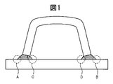
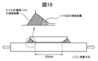
- FIG. 1 is a view showing an example of a welded joint and a welded structure.
- FIG. 1 is a schematic diagram for explaining a structure when a member having a U-shaped cross section is attached to a flat plate by welding to ensure bending rigidity.
- FIG. 1 In the case of the example shown in FIG. 1, the U-shaped member is welded to the flat plate at two locations, and the joint is a T-shaped joint. At this time, since fatigue cracks occur in the stress concentration portion, they occur in the four locations indicated by reference signs A to D in the example shown in FIG.
- the two locations indicated by reference signs A and B are located outside the welded structure, so that it is easy to carry out repairs, and the shape of the weld toe is processed smoothly in advance. It is possible to improve the fatigue strength by performing a peening process and applying compressive residual stress.
- the two weld toes indicated by reference characters C and D in FIG. 1 are structurally sealed and cannot be post-processed after the end of welding.
- This is a very simple process in which, in the case of a mechanical post-processing method such as peening, the processing must be performed while directly contacting a portion where fatigue is a problem (see reference numerals C and D in FIG. 1).
- the fatigue strength of the welded structure as shown in FIG. 1 is determined by the fatigue strength of the weld toe indicated by symbols C and D, and the fatigue strength of the weld toe indicated by symbols A and B.
- the problem remains that the fatigue strength of the entire welded structure is not improved.
- the technique disclosed in the document only discloses a technique for a joint when the weld toe is located outside.
- the welding material disclosed in Patent Document 1 is not necessarily used. Not obvious.
- the welding of the T-joint is completed by two-pass welding, but in this case, the heat generated when forming the subsequent weld bead, that is, the outer weld bead, is generated by the inner bead. Since the residual stress is broken, the original effect cannot be obtained.
- the fatigue strength of a welded structure is a factor that determines the life of the entire welded structure, and in particular, the fatigue strength of the entire welded structure is determined at a portion where the fatigue strength is lowest.
- the present invention has been made in view of the above problems, and mechanical treatment such as shot peening is applied to the weld toe portion or root portion where fatigue strength is a problem due to the existence of a sealed region in structure.
- Another object of the present invention is to provide a method for manufacturing a welded joint capable of improving fatigue strength when measures for improving fatigue strength by welding such as bead formation cannot be taken.
- the present inventors are able to achieve the improvement of the fatigue strength of the welded joint when there is a weld toe portion or root portion having a structure that cannot take measures for improving the mechanical fatigue strength.
- This invention is made
- the multi-pass welding is performed such that the transformation start temperature of the weld metal in the first pass is in the range of 175 ° C to 400 ° C.
- a first welding step in which welding is performed using a material, and then welding in which the weld metal is raised in one or more passes so that a part of the weld metal formed in the first welding step becomes an unmelted portion.
- a second welding step for retransforming all the unmelted portions into austenite by the welding heat of the final pass.
- the multi-pass welding is performed such that the transformation start temperature of the weld metal in the first pass is in the range of 175 ° C to 400 ° C.
- a first welding process in which welding is performed using a material, and then the weld metal is raised in one or more passes so that a part of the weld metal formed in the first welding process becomes an unmelted portion.
- a method for manufacturing a welded joint comprising: a second welding step for performing welding, and then a heat treatment for retransforming all the unmelted portions into austenite.
- the weld joint is a T joint, and the joint portion of the T joint is composed of an unwelded portion and welded portions on both sides sandwiching the unwelded portion, and the welded portion is subjected to multi-pass welding by partial melting welding only from one side.
- a method for manufacturing a joint is a cruciform joint, and a joint portion of the cruciform joint is composed of an unwelded portion and welded portions on both sides sandwiching the unwelded portion, and the welded portion is subjected to multi-pass welding by partial melting welding only from one side.
- the length of the unwelded portion existing between the multipass welds and the minimum thickness of the steel plate forming the T joint are the A method for manufacturing a welded joint, characterized in that it is at least three times the maximum thickness of each pass weld bead in pass welding.
- the weld joint is a T joint or a cross joint, and a joint portion of the weld joint includes an unwelded portion and welded portions on both sides sandwiching the unwelded portion, and the welded portion is subjected to partial melting welding only from one side.
- any one of (1) to (11) is characterized in that post-processing is performed by grinder processing on the toe portion of the weld bead on the welding side.
- a method for producing a welded joint according to claim 1. Any one of (1) to (11) is characterized in that after the second welding step, post-treatment by peening treatment is performed on the toe portion of the weld bead on the welding side.
- a method for producing a welded joint according to claim 1. (14) After the second welding step, the toe portion of the weld bead on the welded side is subjected to a reheating treatment with a TIG arc, (1) to (11) The manufacturing method of the welded joint in any one.
- a welded joint of the present invention there is an inner weld toe or root portion having a structure that cannot be post-processed mechanically or by welding due to the structure of the welded joint or the structure of the welded structure. Even in this case, the fatigue strength of the welded joint can be improved, the life of the entire welded structure can be improved, or the existing welded structure can be repaired to prolong the life of the welded structure.
- the industrial significance is extremely large.
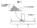
- FIG. 1 It is a schematic diagram for demonstrating an example of the manufacturing method of the welded joint of this invention, and is a partial expanded sectional view which shows the weld part of the welded joint shown in FIG.
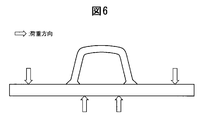
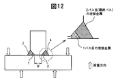
- FIG. 1 It is a schematic diagram for demonstrating the Example of the manufacturing method of the welded joint of this invention, and is sectional drawing which shows the load direction at the time of conducting the fatigue test in Example 1.
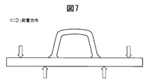
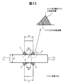
- FIG. 1 It is a schematic diagram for demonstrating the Example of the manufacturing method of the welded joint of this invention, and is sectional drawing which shows the load load direction at the time of conducting the fatigue test in Example 3.
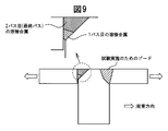
- FIG. It is a schematic diagram for demonstrating the welded joint of this invention, and is the elements on larger scale which show the weld part of the square joint in Example 5.
- FIG. 1 It is a schematic diagram for demonstrating the Example of the manufacturing method of the welded joint of this invention, and is sectional drawing which shows the load loading direction at the time of conducting the fatigue test of the corner joint in Example 5.
- FIG. It is a schematic diagram for demonstrating the Example of the manufacturing method of the welded joint of this invention, and is sectional drawing which shows the load load direction at the time of conducting the fatigue test of the lap joint in Example 5.
- FIG. It is a schematic diagram for demonstrating the Example of the manufacturing method of the welded joint of this invention, and is sectional drawing which shows the load load direction at the time of conducting the fatigue test of the T joint in Example 5.
- FIG. 1 It is a schematic diagram for demonstrating the Example of the manufacturing method of the welded joint of this invention, and is sectional drawing which shows the load load direction at the time of conducting the fatigue test of the T joint welded from both sides in Example 6.
- FIG. It is a schematic diagram for demonstrating the Example of the manufacturing method of the welded joint of this invention, and is sectional drawing which shows the load direction at the time of conducting the fatigue test of the cross joint in Example 6.
- FIGS. 1 to 13 an embodiment of a method for manufacturing a welded joint according to the present invention will be described with reference to FIGS. 1 to 13 as appropriate.
- this embodiment is described in detail in order to make the purpose of the manufacturing method of the welded joint of the present invention better understood, the present invention is not limited unless otherwise specified.
- the fatigue strength improving methods are roughly divided into three types.
- the first is a method of applying mechanical or mechanical treatment such as impact to the surface, such as shot peening
- the second is to adjust the composition of the weld metal and use the transformation expansion of the weld metal.
- a method of adding ingenuity to material characteristics such as components of steel or welding material
- the third is a method of applying heat after welding.
- these methods will be called a mechanical method, a material method, and a heat treatment method, respectively.
- the present invention can be said to be a method using both a materialistic method and a heat treatment method.
- the present invention aims to improve the fatigue strength of a welded joint having a structure in which a fatigue strength improving method such as mechanical treatment cannot be performed.
- a structure has a partially sealed structure as a welded structure, or as a welded joint, there is an unwelded part such as a partial penetration, so that direct peening treatment or Indicates a case where grinder processing cannot be performed.
- a low-temperature transformation melt such a component-based welding material
- the weld metal formed at that time is called a low-temperature transformation weld metal.
- the low-temperature transformation melt contains a large amount of Ni, Cr, etc., and is also a component system that easily generates hot cracks. In such a case, depending on the shape of the joint, if one-pass welding is performed, butt solidification is likely to occur in the weld metal, and the risk of causing hot cracking is extremely high.
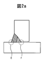
- Such joints that cannot take measures to improve fatigue strength by mechanical treatment, etc., include a case where a sealed space exists as shown in FIG. 1 as well as a partial penetration as shown in FIG. 2a.
- a sealed space exists as shown in FIG. 1 as well as a partial penetration as shown in FIG. 2a.
- a welded joint by welding since there is an unwelded portion even if there is no sealed space, it is directly mechanically applied to a stress concentration portion (see the portion indicated by symbol F in FIG. 2a) where fatigue becomes a problem.
- processing cannot be performed As shown in FIG. 1, when a mechanical treatment cannot be performed due to the presence of a sealed space, the locations indicated by reference characters C and D in FIG. 1 are called inner weld toes and are shown in FIG. 2a.
- a case where an unwelded portion exists is referred to as a root portion.
- the above-described fatigue strength problem of the inner weld toe portion 21 and the root portion 41 on the sealed space side is solved as follows.
- two methods are disclosed: a case where heat treatment is not performed after welding (see claim 1) and a case where heat treatment is performed (see claim 2).
- the former is referred to as a non-heat treatment type, and the latter is referred to as a heat treatment type.
- the method for manufacturing a non-heat treatment type welded joint includes a steel material 11 (of the welded joint 10 (30) in terms of the structure of the welded joint or the welded structure. 31) is a structure that can be welded only from one side, and the inner weld toe portion 21 covered with the welded structure 1 or the route portion 41, which is formed by partial penetration welding and cannot be accessed from the outside, is mechanical. Or it is a method of manufacturing a welded joint 10 (30) having a structure that cannot be post-processed by welding.
- the insoluble Second which introduces compressive residual stress to the inner weld toe portion 21 or the root portion 41 by performing welding that heats up the weld metal in one pass with welding heat input that is heated until the melted portion is retransformed into austenite. And a welding process.
- a weld bead inner weld toe, Root part
- This weld metal is a low-temperature transformation weld metal.
- a second weld bead (outer weld toe) is formed as a subsequent bead. This corresponds to the second welding process.
- a melt suitable for the strength of the steel plate forming the welded structure that is, a normal welding material, or a low-temperature transformation melt.
- a normal welding material for forming the second bead from the viewpoint of selecting a material having low hot cracking sensitivity.
- the weld joint is formed by two-pass welding, but simply by performing two-pass welding, the compressive residual stress formed by the first weld bead due to the low-temperature transformation melt disappears by the second bead. There is a danger that the fatigue strength will not improve. Therefore, when the second welding process is performed, it is necessary to generate the compressive residual stress again after the initially formed compressive residual stress disappears.
- the technical idea that forms the basis of the present invention is that the compressive residual stress is again generated by the second weld bead. That is, the compressive residual stress that improves the fatigue strength is not a residual stress that occurs when welding using a low-temperature transformation melt, but a residual stress that occurs when the second welding is performed.
- a low temperature transformation material in the prior art is a technology that introduces compressive residual stress by utilizing transformation expansion, and this compressive residual stress is generated in the cooling process during welding using the low temperature transformation material.
- this compressive residual stress corresponds to the compressive residual stress generated in the first-pass welding, but in the present invention, this compressive residual stress disappears in the second welding.
- the technical idea forming the basis of the present invention is to generate compressive residual stress again at the second welding, and further, the welding material used for the second welding is not necessarily limited to the low-temperature transformation melt.
- the untransformed part is only thermally contracted during the subsequent cooling and does not undergo transformation expansion. Sufficient compressive residual stress cannot be generated again. Further, even if welding is performed so as to simply cover the surface of the low temperature transformation weld metal formed by the first welding, the low temperature transformation weld metal formed by the first welding cannot be retransformed into austenite.
- part or all of the low temperature transformation weld metal formed in the first welding process needs to be unmelted. If all the low temperature transformation weld metal is melted in the second welding, the compressive residual stress is not reintroduced. On the other hand, in the final welding pass in the second welding process, all of the unmelted low temperature transformation weld metal must be heated before retransformation to austenite. It is not particularly difficult to examine such conditions in advance if it is a person concerned with welding. Prepare a specimen having the same shape as the actual weld joint in advance, and perform the first welding process and the second weld process with the same welding material as the welding material to be used when actually welding.
- the unmelted low temperature This is because whether or not all of the transformation weld metal has retransformed to austenite can be easily determined by observing the structure of the cross-sectional macro.
- the welding conditions may be determined in advance, and welding may be performed on the actual welded joints under these conditions.
- the transformation start temperature of the low temperature transformation weld metal can also be confirmed by collecting a test piece from the unmelted low temperature transformation weld metal portion of the weld joint prepared in advance and measuring the transformation start temperature.
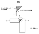
- the joint is a joint called a T joint, but the present invention aims to improve the fatigue strength by controlling the residual stress. If the effect is negligible, it is considered that there are two welds that are welded only from one side. In this case, the unwelded portion corresponds to a sealed space sandwiched between the welds on both sides. The fact that it is far enough not to affect the residual stress also depends on the welding heat input. When the heat input amount is high, the thickness of the weld metal formed in the welding pass at that time also increases. Therefore, in the present invention, the thickness of the weld metal is employed instead of the heat input amount. In the present invention, the thickness of the weld metal is defined as shown in FIG.
- one point A on the surface of the weld metal is determined.
- a tangent of the weld metal surface at A is determined, and then a straight line that intersects the tangent perpendicularly and passes through the point A is obtained.
- the intersection of this straight line and the fusion line of the weld metal is defined as B, and the distance between point A and point B is defined as the thickness at point A.
- the thickness is defined at each point of the weld metal, and the maximum value is determined as the thickness of the weld metal.
- the weld metal surface disappears. Therefore, it is necessary to determine the thickness after each welding pass and before the subsequent welding pass is performed. It is necessary to pay attention to.
- the maximum value is compared with the length of the unwelded part, and when the length of the unwelded part is more than three times the maximum value, It has been found that the existing weld metals can be regarded as independent of each other and do not affect the residual stress. When the unwelded portion is shorter than this, the welding process on one side affects the residual stress on the other side, and the fatigue strength may not always improve, so this value was set.
- the cross joint it can be considered that a T-joint welded from both sides is formed on each of the front side and the back side of one steel plate.
- the limiting conditions for forming the respective T joints must satisfy the limiting conditions set when forming the T joints.
- the cross joint in addition to this condition, it is necessary to pay attention to the welding heat transmitted through the steel plate. In this case, it is sufficient that the plate thickness is thick enough not to affect the residual stress.
- the unwelded portion and the minimum thickness of the steel plate forming the cross joint are more than three times the maximum thickness of the weld metal formed in each welding pass, the newly formed weld metal was found to be independent of each other and not to affect the residual stress.
- the unwelded portion is shorter than this, the welding process on one side affects the residual stress on the other side, and the fatigue strength may not always improve, so this value was set.
- the above is the technical idea of the present invention in the non-heat treatment type fatigue strength improving method.
- the transformation of the above-mentioned low temperature transformation weld metal is not necessarily limited to a specific transformation as long as it is a volume expansion transformation that occurs at a low temperature defined by the present invention, but is generally within the temperature range of the present invention.
- the transformation that occurs in is the martensitic transformation.
- the martensitic transformation start temperature is characterized by being determined only by the weld metal component without depending on the cooling rate during welding.
- the estimation formula using a component is also known, for example, the following estimation formula is proposed.
- Ms 719-795C-20Cr-32Ni-35.6Si-13.3Mn-23.7Mo-11.9Nb
- Ms is the martensitic transformation start temperature (° C.), and C and the like indicate weld metal component values (mass%).
- the existence of such an estimation formula is a convenient index that can be a guide for material development for welding engineers. It should be noted that the transformation that occurs in the temperature range of the present invention is mainly the martensitic transformation in the heat treatment type described below.
- the manufacturing method of the heat treatment type welded joint in the present invention is the method of manufacturing the welded joint 10 (30) having the structure of a welded joint or a welded structure as described above.
- a first welding step for performing welding in which the root portion 41 is formed using a weld metal having a transformation start temperature in the range of 175 ° C. to 400 ° C., and an inner weld toe portion formed in the first welding step A second welding process in which welding is performed to raise the weld metal in one or more passes so that at least a part of the weld metal forming 21 or the root part 41 becomes an unmelted part, and then the first welding process.
- the low temperature transformation weld metal formed in the first welding step is heated by the second welding step until all of the low temperature transformation weld metal is retransformed into austenite.
- heat treatment is performed after welding, and this heat ensures that all of the low temperature transformation weld metal parts are This is a method of retransformation to austenite. Therefore, compared with the non-heat treatment type, the first welding process is the same as the heat treatment type, and as the second welding process, a part of the low temperature transformation weld metal formed in the first welding process is unmelted.
- the welding material does not necessarily need to use a low-temperature transformation melt.
- all or part of the low temperature transformation weld metal unmelted portion formed in the first welding process is not necessarily austenite in the final welding pass of the second welding process.
- the welded joint thus prepared is then processed in a heat treatment step, and then a cross-sectional macro is taken from the welded joint to determine whether there is an unmelted portion of the low temperature transformation weld metal, Whether or not all of the unmelted low-temperature transformation weld metal has been retransformed into austenite by heat treatment may be determined from the observation of the structure of the cross-sectional macro. In this way, welding conditions and heat treatment conditions are determined in advance, and an actual welded joint may be constructed under these conditions.
- the transformation start temperature of the low temperature transformation weld metal can also be confirmed by collecting a test piece from an unmelted low temperature transformation weld metal portion of a weld joint prepared in advance and measuring the transformation start temperature.
- the second welding process has two or more passes in the non-heat treatment type
- the final pass of the second welding step is separated from the weld metal formed in the first welding step, so It is desirable to limit the welding process 2 to the case of 1-pass welding.
- transformation start temperature of weld metal used in the first welding process First, the reason for limiting the transformation start temperature of the low temperature transformation weld metal will be described.
- fatigue is a problem, and a low temperature transformation weld metal is formed at the inner weld toe or root portion where fatigue strength improvement measures cannot be implemented by mechanical or welding post-treatment, and the transformation expansion of the low temperature transformation weld metal
- compressive residual stress is introduced into the weld toe or root.
- the upper limit of the transformation start temperature 400 ° C., was set at a transformation start temperature higher than this, because the thermal shrinkage after the end of transformation increased and the compressive stress introduced during transformation expansion disappeared.
- the lower limit of 175 ° C. has almost the same effect even when the transformation start temperature is lower than this, and in order to obtain a transformation start temperature lower than 175 ° C., This value was set because an alloying element material exceeding the limited range must be added, and the cost of welding material production and the risk of hot cracking increase.
- Heat treatment method in heat treatment process Next, a heat treatment method in the heat treatment mold will be described.
- a method for heat-treating the welded joint a method such as heating with a gas burner, energization heating with an electric heater, or putting the entire structure into a heat treatment path can be considered.
- a heat treatment method by electric heating or induction heating is preferred. Electric heating or induction heating and heating by a gas burner or an electric heater are greatly different in the following points.
- Electric heating is a method in which an electric current is passed through a welded joint and heated using Joule heat generated at that time.
- Induction heating is a method in which an eddy current is generated and heated using that. appear.
- heat is transferred from the joint surface to the inside of the joint by heat conduction.
- the subject of the present invention is the fatigue of the inner weld toe or root that cannot be post-processed mechanically or welded due to the structure, and therefore cannot be directly exposed with a gas burner or the like even when heat treatment is performed. . Therefore, in order to retransform low temperature transformation weld metal into austenite by heat treatment, it is necessary to continue heating until heat is conducted to the low temperature transformation weld metal.
- Ni-based components First, the reason for limiting the component range of Ni-based materials will be described.
- C carbon 0.01 to 0.15% C serves to lower the Ms temperature by adding it to iron.
- the upper limit was made 0.15%.
- C when C is not added, martensite is difficult to obtain, and the residual stress must be reduced only with other expensive elements, which is not economical.
- the reason for limiting the addition to 0.01% or more of C was to use C, which is an inexpensive element, and set it as the minimum value that would bring about its economic merit.
- the upper limit of C is more preferably set to 0.10% from the viewpoint of weld metal cracking.
- Si silicon 0.2-0.8% Si is known as a deoxidizing element. Si has the effect of lowering the oxygen level of the weld metal. Especially during welding, there is a risk of air being mixed during welding, so it is extremely important to control the amount of Si to an appropriate value.
- the lower limit of Si when the Si content is less than 0.2%, the Si content of the low-temperature transformation welding material is also low. In this case, there is a risk that the deoxidizing effect is weakened, the oxygen level in the weld metal becomes too high, and mechanical properties, particularly toughness, are deteriorated. Therefore, in the present invention, the lower limit is set to 0.2%. On the other hand, excessive addition of Si also causes toughness deterioration, so the upper limit was made 0.8%.
- Mn Manganese
- Ni is austenite by itself, that is, a metal having a face-centered structure, and is an element that makes the austenite state more stable when added to the weld metal.
- Iron itself has an austenite structure at high temperatures and a ferrite or body core structure at low temperatures.
- Ni is added, the face-centered structure in the high-temperature region of iron becomes a more stable structure, so that it becomes a face-centered structure even in a lower temperature region than in the case where Ni is not added. This means that the temperature at which it transforms into a body-centered structure is lowered.
- the lower limit of Ni of 7.0% was determined in the sense of the minimum addition amount at which the residual stress reduction effect appears.
- the upper limit of 11.5% of Ni does not change much in effect from the viewpoint of reducing residual stress, and in addition to adding more than this, there is an economic disadvantage that Ni is expensive. This is because there is a risk of hot cracking.
- the lower limit of Ni is more preferably set to 8.0% in order to surely improve the fatigue strength. The above is the reason for limitation to the Ni-based essential components in the present invention.
- group other than the said essential component the following components can be selectively added as needed.
- Cu Copper
- Cu Copper
- 0.05-0.4% Cu is an effective element for improving welding workability because, when the welding material is a wire, it has the effect of improving the electrical conductivity by plating on the wire.
- excessive addition is not preferable in the industry because the effect of improving workability is saturated, and further, the wire manufacturing cost is increased.
- the upper limit of Cu of 0.4% is set for this reason.
- the lower limit of 0.05% of Cu was set as a minimum value at which the effect of improving the electrical conductivity was obtained.
- Nb niobium
- Nb carbide works to increase the strength of the base metal and the weld metal in a small amount, and therefore, the economic merit of effective use is great.
- the lower limit of Nb was set to 0.005% as the lowest value at which carbides can be formed and an effect of increasing strength can be expected.
- the upper limit of Nb is set to 0.1% because the effect of increasing the strength is saturated even if the problem of weld cracking due to a significant increase in strength and the problem of weld cracking can be avoided.
- V Vanadium
- V Vanadium
- Nb vanadium
- the lower limit of 0.01% for V addition is set as the lowest value at which precipitation hardening can be expected by addition.
- the upper limit of V is added more than this, precipitation hardening becomes too remarkable, and even if excessive addition is carried out, the improvement is saturated from the viewpoint of fatigue improvement effect, and further, excessive precipitation hardening is caused. Therefore, the problem of weld cracking occurs, so 0.5% was set.
- Ti Titanium 0.005 to 0.1% Ti, like Nb and V, forms carbides and causes precipitation hardening.
- the precipitation hardening of V is different from that of Nb
- the precipitation hardening of Ti is also different from Nb and V. Therefore, the range of the addition amount of Ti is also set to a range different from Nb and V.
- the lower limit of Ti addition amount of 0.005% is the minimum amount at which the effect can be expected, and the upper limit of Ti of 0.1% is excessively added, the fatigue strength improving effect is saturated, and excessively Since the problem of cracking also occurs due to the precipitation effect, this value was set.
- Cr chrome 0.1-3.0% Cr is a precipitation hardening element like Nb, V, and Ti.
- Cr has an effect of reducing the Ms temperature, and is therefore an element that should be used effectively.
- the Cr addition amount should be less than that of Ni. Excessive Cr addition does not necessarily improve the residual stress reduction effect and is not industrially preferable because Cr is expensive.
- the lower limit of 0.1% of the Cr addition amount was set as a minimum value at which the residual stress reduction effect was obtained by adding this.
- the upper limit of the Cr addition amount is 3.0% for the Ni type because the Ms temperature has already been reduced by the addition of Ni and the strength is secured by other precipitation elements. However, the residual stress reduction effect is not changed so much.
- Mo Molybdenum 0.1-2.0%
- Mo is an element having the same effect as Cr.
- Mo is an element for which precipitation hardening can be expected more than Cr. Therefore, the addition range was set narrower than Cr.
- the lower limit of 0.1% was set as the minimum value at which the effect of Mo addition can be expected.
- 2.0% of the upper limit of Mo was set because the fatigue strength improvement allowance would be saturated even if added more than this.
- group since the transformation start temperature is mainly achieved by Ni, it is desirable to set the minimum of the transformation start temperature of Ni type
- Si silicon 0.1-0.7% Si is known as a deoxidizing element.
- Si silicon
- the lower limit of Si when the amount of Si in the low temperature transformation weld metal is less than 0.1%, it means that the amount of Si in the low temperature transformation welding material is also low, and the deoxidation effect is diminished and the low temperature transformation. There is a risk that the oxygen level in the weld metal becomes too high, leading to degradation of mechanical properties, especially toughness. Therefore, the lower limit of the Si content of the low temperature transformation weld metal is set to 0.1%.
- the lower limit of Si is more preferably 0.30%. On the other hand, even if Si addition exceeding 0.7% is performed, the workability improvement effect is saturated, so the upper limit was made 0.7%.
- Mn Manganese 0.1-2.0%
- Mn is used as an element for increasing the strength, but in the Cr—Ni system in the present invention, the effect has already been obtained by Cr or the like. Therefore, the addition of Mn is mainly aimed at the deoxidation effect as in Si.
- the lower limit of 0.1% of Mn was set as the minimum value at which a deoxidizing effect was obtained.
- the upper limit of 2.0% was set to 2.0% because the deoxidation effect allowance would be saturated even if more additions were made.
- Ni nickel 4.0-8.0%
- Ni is a single austenite, that is, a metal having a face-centered structure. Iron itself has an austenite structure at a high temperature range and ferrite, that is, a body-centered structure at a low temperature range. When Ni is added, the face-centered structure in the high-temperature region of iron becomes a more stable structure, so that it becomes a face-centered structure even in a lower temperature region than in the case where Ni is not added. This means that the temperature at which it transforms into a body-centered structure is lowered. Moreover, Ni has the effect of improving the toughness of the weld metal by adding it.
- the lower limit of 4.0% of the addition amount of Ni in the Cr-Ni low temperature transformation weld metal was determined from the viewpoint of securing the minimum addition amount and toughness in which the residual stress reduction effect appears.
- the upper limit of the Ni addition amount is 8.0% in the case of Cr-based welding wires, since the Ms temperature is reduced to some extent by the addition of Cr described below, and from the viewpoint of reducing residual stress, the upper limit of Ni addition amount is However, the effect is not changed so much, and if it is added more than this, an economic demerit that Ni is expensive is caused, so this value was set.
- Cr Chromium
- Cr Chromium
- the upper limit of 15.0% of Cr is that when the amount exceeding this is added, the transformation temperature becomes too low and the transformation expansion amount becomes small, so that the effect of improving fatigue strength tends to decrease.
- the above is the reason for limiting the Cr—Ni-based essential components in the present invention.
- the following elements can be selectively added to the Cr—Ni system in the present invention.
- the purpose of adding the following components is not necessarily intended to improve the fatigue strength, but whether or not to add can be easily determined by those involved in welding.
- Cu Copper
- 0.05-0.4% Cu is an effective element for improving welding workability because it has the effect of improving the conductivity by plating on the low-temperature transformation welding material when it is a wire.
- the lower limit of 0.05% of Cu is that the amount of Cu plated on the wire is also lower when the Cu in the low temperature transformation weld metal is lower than this.
- the limit value was set.
- excessive addition of Cu not only has an effect of improving workability but also increases the wire manufacturing cost, which is not preferable from an industrial viewpoint.
- the upper limit of Cu of 0.4% is set for this reason.
- Nb niobium
- Nb carbide works to increase the strength of the weld metal in a small amount, and therefore, the economic merit of effective use is great.
- excessive carbide formation has an excessively high strength and causes a problem of weld cracking and deterioration of toughness.
- the lower limit of Nb was set to 0.005% as the lowest value at which carbides can be formed and an effect of increasing strength can be expected.
- the upper limit of Nb is set to 0.1% as a value that prevents the problem of cracking and does not impair the reliability of the weld due to toughness deterioration.
- V Vanadium
- V Vanadium
- the lower limit of V addition of 0.01% was set as the lowest value at which precipitation hardening can be expected by addition.
- the reason for setting the upper limit of V is the same as in the case of Nb, and if added more than this, precipitation hardening becomes excessively significant, causing toughness deterioration, and from the viewpoint of causing weld cracking due to excessive hardening, the upper limit is set to 0. 0.5%.
- Ti Titanium 0.005 to 0.1% Ti, like Nb and V, forms carbides and causes precipitation hardening.
- the range of the addition amount of Ti is also set to a range different from Nb and V.
- the lower limit of 0.005% of the Ti addition amount is determined as the minimum amount at which the effect can be expected, and the upper limit of 0.1% is determined from the viewpoint of preventing toughness deterioration and excessive weld cracking due to steel.
- Mo Molybdenum 0.1-2.0% Mo is also an element that can be expected to precipitate and harden like Nb, V, and Ti. However, Mo needs to be added more than Nb, V, Ti in order to obtain the same effect as Nb, V, Ti.
- the lower limit of 0.1% of the Mo addition amount was set as the minimum value at which an increase in yield strength due to precipitation hardening can be expected. Further, 2.0% of the upper limit of Mo is set to this value because the fatigue strength improvement allowance is saturated even if it is added more than this.
- the present invention relates to a method for improving the fatigue strength of the inner weld toe portion or the root portion where measures for improving the fatigue strength by mechanical treatment or the like cannot be implemented. Therefore, the weld toe portion on the side where welding is performed is not necessarily an object of the present invention. However, when a fatigue crack can improve the fatigue strength of one part, the fatigue strength of another part will determine the fatigue strength of the whole joint. Therefore, the inventors further improve the fatigue strength of the inner weld toe portion or the root portion on the side where the fatigue strength improvement measures cannot be implemented by mechanical or welding post-processing, and then further increase the fatigue strength of the opposite side. It was considered industrially significant to provide measures to improve the fatigue strength of parts.
- Measures to improve fatigue strength can be broadly divided into methods that reduce residual stress and methods that relieve stress concentration.
- a method for reducing the residual stress there is a method in which the entire structure is uniformly heated and then gradually cooled.
- the compressive residual stress introduced by the low-temperature transformation weld metal is lost, so even if it is a measure for improving fatigue strength, it cannot be applied without limitation.
- one or both of the outer weld toe portions 22 (42) on both sides of the weld bead on the welding side formed in the second welding step reference numerals 22a and 22b in FIGS. 1 and 2). , 42a and 42b), the shape of the outer weld toe 22 (42) subjected to the post-processing is smoother than that of the as-welded state by performing post-processing by machining such as grinder processing. It can be set as the method of performing the mechanical post-processing processed into.
- the method in which the weld toe is machined more smoothly than in the as-welded state is a method that relieves stress concentration, and does not significantly affect the residual stress introduced by the low-temperature transformation weld metal. Therefore, it is a preferable method as a fatigue strength improving method applied to the joint targeted by the present invention.
- post-processing by peening such as shot peening, ultrasonic peening, air peening, or the like on one or both of the outer weld toe portions 22 (42) on both sides of the weld bead on the side where welding is performed.
- peening such as shot peening, ultrasonic peening, air peening, or the like
- the shape of the outer weld toe portion 22 (42) subjected to the post-processing is processed more smoothly than the as-welded state, and the compressive residual stress is applied to the outer weld toe portion 22 (42).
- This can be a method of performing mechanical post-processing.
- Fatigue strength improvement measures by post-processing of peening treatment such as ultrasonic peening introduces compressive residual stress to the treated part in addition to the effect of relieving stress concentration. Bigger than the case. Further, since it does not significantly affect the residual stress introduced by the low temperature transformation weld metal, it is a preferable method as a fatigue strength improving method applied to the joint targeted by the present invention.
- this TIG welding is performed by performing TIG welding (TIG tanning welding) which does not use a filler material with respect to one or both of the outer weld toe portions 22 (42) on both sides of the weld bead. It can be set as the method of performing the post-process by welding which processes the shape of the outer side weld toe part 22 (42) which gave smooth rather than the state as-welded.
- TIG welding TIG tanning welding
- TIG tanning welding is a method of relieving the stress concentration at the weld toe, etc. by remelting the joint surface with welding arc heat without using a welding material.
- the method of applying heat to a welded joint requires caution in its use because it may eliminate the compressive residual stress introduced by the low temperature transformation weld metal.
- TIG tanning welding is preferable because it can achieve sufficient stress relaxation with a small heat input even if it is a method of applying heat, so that it can be applied to the joint targeted by the present invention. Is the method.
- welding in which one or both of the outer weld toe portions 22 (42) on both sides of the weld bead have the same component and transformation start temperature as the weld metal used in the first welding step.
- a post-process for forming a weld bead (decorative bead) that is a metal a post-process by welding is performed to introduce compressive residual stress to the outer weld toe 22 (42) subjected to the post-process.
- the method can be adopted.
- the method of forming a decorative bead on the weld toe portion on the side where welding is performed using the same welding material as that used to form the low-temperature transformation weld metal in the first welding process has a small amount of welding and a welded joint.
- This is a preferable method that can be applied to the joint that is the subject of the present invention.
- this method is a method for controlling the residual stress.
- the TIG tanning welding method for applying the same heat to the joint is a method for reducing the stress concentration, and the method for improving the fatigue strength is different.
- the TIG tanning welding method can be performed either before or after the heat treatment, but the method of forming the decorative bead needs to be performed after the heat treatment. is there. This is because if the cosmetic bead is formed before the heat treatment, the compressive residual stress formed by the cosmetic bead during the heat treatment disappears. If the decorative bead is formed before the heat treatment, it is necessary to set heat treatment conditions so that both the low temperature transformation weld metal formed during the first welding process and the weld metal of the decorative bead are retransformed to austenite. However, in this case, since the heating width becomes wide, the residual stress due to heat treatment and the risk of introducing deformation increase. Therefore, in the present invention, when adopting the heat treatment type fatigue strength improving method, it is desirable that the decorative bead is carried out after the heat treatment.
- the welded joint manufacturing method of the present invention direct mechanical processing of a structure that cannot be mechanically or post-processed by welding due to structural problems of the welded joint or the structure of the welded structure. Even if there is an inner weld toe or root that cannot be performed, the fatigue strength of the welded joint can be improved, the life of the entire welded structure can be improved, or the existing welded structure Can extend the life of the welded structure by repairing it, and it has great industrial significance.
- Example 1 is an example of a non-heating type fatigue strength improvement measure.
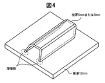
- a structure as shown in FIG. 4 was assembled by welding. The state of the welded portion at that time was as shown in FIG.
- the upper plate thickness in FIG. 4 was set to 6 mm.
- various welding materials were made as prototypes.
- SMAW manual welding
- GMAW carbon dioxide gas welding
- the amount of heat input was changed.
- the amount of heat input is described for the second pass SMAW.
- the second-pass welding material there are a case where the same welding material as that in the first pass is used and a case where a normal welding material, that is, a welding material having a strength level in the range of 490 MPa to 780 MPa is selected. In either case, the above conditions were adopted as the welding conditions.
- the welding conditions are limited to the above welding conditions. is not.
- the normal welding material the following components (welded metal components) were used.
- FIG. 6 is a schematic diagram showing a load application direction when a fatigue test is performed, and an arrow in FIG. 6 indicates a load application direction.
- the fatigue test was performed by a four-point bending test, and the fatigue load was measured by attaching a strain gauge to the inner weld toe of the weld metal formed in the first welding process. Note that the strain gauge was able to be attached because it was a specimen, and it is considered difficult to measure stress with the strain gauge in the case of an actual welded structure.
- Table 1 below shows the measurement results of the components and transformation start temperatures of the weld metal formed in the first welding process.
- the weld metal component was measured by collecting a specimen for component analysis directly from the formed weld metal after welding.
- the transformation start temperature is the result of measuring the transformation start temperature by taking a formaster test from the weld metal formed after welding. That is, a round bar-shaped test piece was collected from the weld metal, heated and cooled, and the length of the test piece at each temperature was measured to measure the expansion and contraction of the weld metal, thereby determining the transformation start temperature.
- numbers 1 to 14 indicate that the weld metal component and the transformation start temperature are within the scope of the present invention.
- the present invention relates to a method for improving fatigue strength
- the present invention is not necessarily an example of the present invention if the weld metal component and the transformation start temperature are within the scope of the present invention.
- the components and transformation start temperatures within the scope of the present invention are described as examples of the present invention.
- the components of the weld metal shown in Table 1 below are examples of Ni-based components in the present invention.
- Table 2 the components of the weld metal formed in the first welding step when a test body as shown in FIG. 4 was produced with a welded joint as shown in FIG.
- the transformation start temperature was indicated. 4 and 5, welded joints exist on the left and right, but the joints were produced under the same welding conditions.
- numbers 101 to 116 are weld metals within the scope of the present invention.
- the weld metal component and the transformation start temperature are It is not necessarily the case of the present invention that is within the scope of the present invention.
- the components and transformation start temperatures within the scope of the present invention are also described as examples of the present invention.
- Numbers 151 to 162 are comparative examples in the present invention. Among these, numbers 152, 155, 160, 161, and 162 are examples in which cracks and defects occurred in the weld metal, and the transformation start temperature was measured by selecting a weld metal portion in which no cracks occurred. In other comparative examples, cracks and the like are not generated, but since the composition of the weld metal is outside the scope of the present invention, the transformation start temperature is outside the scope of the present invention.
- Table 3 below shows the fatigue strength when the component type weld metals shown in Tables 1 and 2 are formed in the first welding step and a fatigue load as shown in FIG. 6 is applied.
- the fatigue strength at this time was determined as a stress range that does not break even when fatigue load was applied 2 million times.
- the stress range is a value measured by attaching a strain gauge to the test body before the fatigue test is performed in the vicinity of the weld metal side formed by the first-pass welding.
- the fatigue strength of 200 MPa means that the stress range was 0 to 200 MPa, and it did not break even after repeated loading 2 million times.
- SMAW manual welding method
- GMAW gas shield welding method
- [1] means the first welding process
- [2] means the second welding process.
- the components of the weld metal formed in the first welding process are those in Tables 1 and 2, and the weld metal numbers ([1] weld metal numbers) for the respective joints are shown in Table 3 below.
- the same welding material as that in the first welding process is not necessarily used, and a normal 590 MPa class welding material may be used.
- the welding materials (welding materials [2]) used in the second welding step for each joint are also shown in Table 3 below.
- Table 3 also shows the results of whether or not the weld metal formed in the first welding process has been retransformed to austenite by macro test observation.
- J1 to J36 in Table 3 indicate that the weld metal having the components and the transformation start temperature within the scope of the present invention is formed in the first welding step. It is a joint when it retransforms to austenite in the second welding process, and as can be seen from Table 3, the fatigue strengths all exceed 250 MPa.
- J33 to J36 are cases where the strength of the welding material used in the second welding process is different from that of J1 to J32, but because retransformation of the weld metal formed in the first welding process is achieved, It can be seen that the fatigue strength is improved.
- J101 to J111 are comparative examples, and since the transformation start temperature was outside the range of the present invention, the fatigue strength did not reach 250 MPa.
- J101, J103, J105, J108, and J109 are joints in which weld metals of numbers 53 and 55 in Table 1 and numbers 151, 156, and 157 in Table 2 are formed in the first welding process, and transformation starts.
- the temperature after the heating is lower than the range of the present invention.
- These joints are considered to be examples in which the effect of improving the fatigue strength is insufficient because the transformation start temperature is too low and a sufficient transformation expansion amount cannot be obtained.
- J102, J104, J106, J107, J110, and J111 are joints in which weld metals of numbers 54 and 58 in Table 1 and numbers 153, 154, 158, and 159 in Table 2 are formed by the first welding process.
- the transformation start temperature was higher than the range of the present invention and the residual stress reduction was insufficient.
- the four joints J112 to J115 have a second pass from the macro observation even though the transformation start temperature of the low temperature transformation weld metal formed in the first welding process is within the scope of the present invention. Since the heat input was small, it was found that the low temperature transformation weld metal was retransformed to austenite only in a part of the unmelted part in the second welding process. In this case, it is considered that the compressive residual stress introduced in the first welding process disappears and the compressive residual stress is not introduced again in the second welding process, so that the fatigue strength is not improved.
- the transformation start temperature was within the range of the present invention, but the amount of heat input in the second pass was inappropriate, and there was no unmelted portion of the weld metal formed in the first pass.
- the fatigue strength was not improved.
- the fatigue strength improvement effect was confirmed altogether and it became clear that it is industrially significant.
- Example 2 is an example relating to the heat treatment type fatigue strength improving method of the present invention.
- the heat treatment type method in this example in order to make the number of welding passes in the second welding process two, the upper plate thickness in FIG. Added pass welding.
- the total welding is a total of three passes, one pass in the first welding step and two passes in the second welding step.
- two types of induction heating and current heating were selected. Induction heating was performed at 2.0 kHz of 20 kW, and energization heating was performed by supplying a current of 250 A to the weld bead.
- Table 4 below shows the results of Example 2.
- the meanings of the welding materials [1] and [2], [1] weld metal number, and [2] of the welding method are the same as in Table 3.
- the determination of retransformation is a determination of whether or not retransformation was performed by heat treatment after the heat treatment.
- the fatigue test was implemented by the same method as Example 1, and let the stress range which was not fractured by 2 million times be the fatigue strength.
- the numbers from J201 to J230 are examples of the present invention when heat treatment was performed by induction heating using a 590 MPa class welding material in the second welding step, and the fatigue strengths all exceeded 250 MPa.
- J231 and J232 are examples of the present invention when the same welding material is used in the second welding process as in the first welding process, and it can be seen that there is an effect of improving fatigue strength.
- J232 to J235 are examples of the present invention in which electric heating is used for heat treatment, and an effect of improving fatigue strength is recognized.
- the weld metal formed in the first welding process is the same as J201, but the strength of the welding material used in the second welding process is 490 MPa and 780 MPa, which is different from J201.
- the fatigue strength exceeds 250 MPa, and this is an example in which the strength improvement effect has been confirmed.
- J301 to J315 in Table 4 are comparative examples in the present invention, and the fatigue strength does not reach 250 MPa, unlike the examples of the present invention.
- J301, J303, J305, J308, and J309 have a lower residual stress reduction because the transformation start temperature of the weld metal formed in the first welding process is lower than the range of the present invention and transformation expansion is insufficient. It is thought that it was not enough.
- J302, J304, J306, J307, J310, and J311 it is considered that the transformation start temperature of the weld metal formed in the first welding process is higher than the range of the present invention, and the residual stress reduction effect itself is small. .
- J312 to J315 have the transformation start temperature of the low temperature transformation weld metal within the range of the present invention, but the heat treatment was insufficient and only a part of the unmelted portion was retransformed to austenite. That was not possible.
- the last comparative example J316 in Table 4 is an example in which the weld metal in the first pass was completely melted by the weld in the second pass, and the unmelted portion disappeared. Therefore, the fatigue strength was not improved. It is an example. As mentioned above, in the case of this invention example, the fatigue strength improvement effect was confirmed altogether and it became clear that it is industrially significant.
- Example 3 in this invention is an example at the time of post-processing as a fatigue strength improvement measure to the outer side weld toe part of the weld metal formed at the 2nd welding process.
- Example 1 and Example 2 since the fatigue strength on the weld metal side formed in the first welding process was considered as a problem, the fatigue test was performed as shown in FIG. , And the difference was made in the stress at the weld metal toe portion formed in the first welding process and the second welding process.
- Example 3 in order to apply the same level of stress as shown in FIG. 7, the position of the inner two fulcrums in the four-point bending test was positioned outside the welded joint. The stress was measured by attaching a strain gauge.
- the arrow in FIG. 7 shows a load load direction.
- Fatigue strength improvement measures applied to the outer weld toe of the weld metal formed in the second welding process are shot peening, TIG tanning welding, ultrasonic peening, low temperature transformation weld metal formation, grinder processing, local heating It is either of stress relief by.
- the welding material used for forming the low temperature transformation weld metal was the same as the welding material used in the first welding process.
- shot peening, ultrasonic peening, and low temperature transformation weld metal formation are methods for introducing compressive residual stress, and among these, the two further have the effect of improving the toe shape.
- TIG tanning welding and grinder processing are methods for improving the toe shape and reducing stress concentration.
- the final stress removal by local heating is a method of eliminating the tensile residual stress of the welded portion, but at the same time, there is a risk of eliminating the compressive residual stress introduced in the first welding process. is there.
- Table 5 below shows the results of Example 3.
- the joint numbers in Table 5 below correspond to the joint numbers in Table 3, which means that measures for improving fatigue strength were applied to the outer weld toes on the second welding process side.
- the processing method shown in the following Table 5 is a countermeasure method for improving fatigue strength at that time.
- [1] means that a fatigue crack has occurred at the inner weld toe on the first welding process side, and [2] 2 occurred at the outer welding toe on the welding process side.
- K1 to K5 and K101 to K105 are examples of the present invention, and K51 and K151 are comparative examples.
- K1 had a fatigue strength of 290 MPa, almost the same value as J1 in Table 3, and the crack generation position was [1]. This is considered that the fatigue strength of [2] became higher than [1] by shot peening.
- a similar tendency is observed for the numbers K3 and K4.
- K2 and K5 fatigue cracks occurred in [2] and the fatigue strength is considered to be lower in [2] than in [1]. Since these are almost the same as J1, in these cases, [1] and [2] are considered to have almost the same fatigue strength.
- a similar tendency is observed for K101 to K105.
- K51 and K151 are stress relief by local heating, that is, SR, and the heating method is heating using a gas burner.
- the fatigue strength does not reach 250 MPa.
- fatigue cracks occurred on the [1] side, that is, from the inner weld toe where the low temperature transformation weld metal was formed. In this example, it is lower than the fatigue strength of Table 3 shown in Example 1 (280 MPa for the J1 joint and 350 MPa for the J28 joint). The reason for this is considered that the compressive residual stress introduced to the first welding process side by local heating has disappeared by local heating.
- Example 4 is an example of measures for improving the fatigue strength of the non-heating type, but the point different from Example 1 is an example when the number of welding passes is 3 or more.
- SMAW was adopted as the welding method.
- the preparation of the test body at that time was the same as in Example 2, and the structure shown in FIG. 4 was adopted.
- the upper plate thickness was 8 mm, the same as in Example 2.
- the first two-pass welding was performed using a 3.2 mm diameter welding rod, and the component values of the weld metal at that time are as shown in Table 6.
- Table 6 four types of two-pass welding were performed.
- the welding conditions are 120A-22V-25 cm / min for each pass.
- a third pass of welding was performed on these four types of joints.
- the welding rod diameter of 4 mm is adopted when the heat input is 1.5 kJ / mm or more, and 3.2 mm is adopted below it. did.
- the welding conditions were 170A-25V for a 4 mm rod diameter and 120A-22V for a 3.2 mm diameter, and the heat input was adjusted by changing the welding speed.
- the number of welding passes of the joint used in Example 4 corresponds to the case where the number of passes is larger than that of 3-pass welding and 2-pass welding shown in Example 1.
- Table 7 shows the fatigue test results of the specimens thus produced.
- L1 to L8 are examples of the present invention, and L51 to L55 are comparative examples.
- the amount of heat input shown in Table 7 is the amount of heat input in the third pass, and it was determined whether or not the weld metal in the first pass was retransformed in this third pass welding. Judgment was made by observation. As can be seen from Table 7, it was confirmed that all of the weld metals in the first pass were retransformed in the inventive examples. On the other hand, in Comparative Examples L51 to L55, since the heat input was low, only a part of the weld metal in the first pass was retransformed. In Comparative Example L56, the amount of heat input was large, so the unmelted portion disappeared. Although the fatigue test was carried out by the loading method shown in FIG.
- Example 5 is an example in which the influence of the joint shape is investigated.
- the effect of forming the weld metal provided by the present invention in the first pass and then retransforming the weld metal formed in the first pass in the final weld pass is verified. Therefore, a joint in which a U-shaped rib structure member is welded to a flat plate was used as the joint shape.
- the essence of the present invention is to retransform the low temperature transformation weld metal formed in the first pass by the final pass welding, and is not limited to such a joint.
- the effect of the present invention was verified with a corner joint, a lap joint, and a T joint that can be welded only from one side because of an unwelded portion.
- the joints employed in Example 5 are the three types of joints shown in FIGS. 8, 10, and 11, which are a corner joint, a lap joint, and a T joint, respectively.
- FIGS. 8, 10, and 11 which are a corner joint, a lap joint, and a T joint, respectively.
- FIGS. 8, 10, and 11 which are a corner joint, a lap joint, and a T joint, respectively.
- FIG. 9 first, welding is performed so that there is no unwelded portion on one side, and thereafter, fatigue characteristics are measured. Welds corresponding to the corner joints intended for investigation were formed.
- the lap joint of FIG. 10 the distance between the left and right lap joint portions was 200 mm.
- the T-joint in FIG. 11 is a partially-penetrating groove that can be welded only from the left side, and is a joint shape that can be welded only from one side.
- welding is SMAW
- the welding condition for the first pass is 130A-23V-14 cm / min
- the welding condition for the second pass final pass
- the welding material for the first pass the same welding material as No. 1 in Table 1 and No. 102 in Table 2 was used, but the components were slightly different depending on the dilution from the base material, and therefore have the components shown in Table 8.
- a weld metal was formed.
- the 590 MPa SMAW welding material shown in Example 1 was used as the welding material for the second pass.
- Table 9 lists the fatigue test results.
- M1 to M6 are examples of the present invention, and M51 to M56 are comparative examples. Whether or not retransformation was performed was confirmed by collecting a macro test piece from the joint and observing the microstructure.
- fatigue results of joints manufactured under two conditions of 2.5 kJ / mm where the welding heat input of the final pass is high and 1.1 kJ / mm where low are listed.
- the weld metal formed in the first pass is all retransformed at 2.5 kJ / mm, but the weld metal formed in the first pass is 1.1 kJ / mm. Only a part of was transformed again.
- the inventive examples had improved fatigue strength compared to the comparative examples.
- the fatigue strength in Table 9 is a value obtained by dividing the fatigue load by the cross section of the welded portion and the value obtained by dividing the other by the steel plate cross section for the corner joint. The reason is that in the joint adopted in Example 5, it was difficult to attach a strain gauge near the weld metal formed by the first-pass welding.
- the three comparative examples in Table 9, M57, M58, and M59 are examples in which the weld metal formed in the first pass was melted and disappeared in the second pass, and the fatigue strength was not improved. It is.
- the fatigue strength was higher than that of the comparative example, and it was proved that the effect of the present invention was effective not only for the T joint but also for other joints.
- Example 6 is an example regarding the T joint and the cross joint that are welded from both sides.
- the thickness of the weld metal in each welding pass is defined, and the thickness and the length of the unwelded portion existing between the welded portions on both sides are compared.
- cross joints consideration is also given to comparison with plate thickness.
- the T joint is formed of weld beads 1, 2, 3, and 4, and the welding order is 1, 2, 3, 4.
- 1 and 3 are low-temperature transformation weld metals, which are 206 component systems shown in Table 8. That is, welding passes 1 and 3 were made of the same material as that used in Example 5. These welding constructions were performed under the same construction conditions as the construction conditions performed with the T joint in Example 5.
- Table 10 shows examples of T joints.
- parameters different in each example number are the thickness of the weld bead 4 and the length W of the unwelded portion.
- the weld bead 4 has the largest thickness among the weld beads 1, 2, 3, 4.
- the case where the length W of the unwelded portion is three times or more than the thickness of the weld bead 4 is an example of the present invention, and an improvement in fatigue strength was confirmed.
- the fatigue strength is not improved.
- Table 10 it turned out that all the fatigue cracks have occurred from the weld bead 1 side. This is presumably because the residual stress on the weld bead 1 side is affected by the weld beads 3 and 4 and the effect of the low temperature transformation weld metal has disappeared.
- Table 11 is an example of a cross joint. It can be considered that the procedure for producing the cross joint is performed by performing the procedure for producing the T joint twice, front and back. Therefore, in this example, a low temperature transformation weld metal of a cruciform joint was produced in the same manner as the T joint.
- the component system of the low temperature transformation weld metal is the same component as 206 in Table 8 in Example 5.
- the cross joint it is necessary to consider the length of the plate thickness t2 as shown in FIG. In FIG. 13, the plate thickness t1 is not described in Table 11 because it does not become shorter than the length W of the unwelded portion.
- weld metals 1, 3, 5, and 7 are low-temperature transformation weld metals, and the component system is the same as 206 in Table 8.
- a welding order it constructed from the weld bead 1 and welded in the same order as the bead number.
- a T-joint is produced with the weld beads 1 to 4, and then the back-side T-joint is produced with 5 to 8, and as the respective T-joint production procedures, N1, One of N2 is applied.
- N1 One of N2 is applied.
- the length of the unwelded portion is sufficiently long, so that the fatigue strength can be improved.
- the cross joint in addition to this, it is necessary to consider the case of affecting the residual stress through the horizontal plate (thickness t2) in FIG. 13, and in the embodiment of the cross joint, the influence of t2 is mainly observed.
- P1 and P2 are examples of the present invention, and P51, P52, P53, and P54 are comparative examples.
- both the front-side T joint and the back-side T joint in FIG. 13 were implemented by the N1 T-joint preparation method of Table 10 that had an effect of improving fatigue strength, but the plate thickness t2 was 10 mm.
- the fatigue strength was not improved because 12 mm and 3 times the maximum weld bead thickness were not reached. The reason for this can be considered that when welding beads 5, 6, 7, and 8 are constructed, their welding heat penetrates to the surface through the horizontal plate.
- t2 is less than three times (21 mm) of the maximum value of the weld bead thickness of 7 mm (21 mm), the fatigue strength is not improved. In the example of the present invention, since this condition is achieved, an effect of improving fatigue strength is confirmed.
- TIG tanning welding is a method of applying heat to the joint, care should be taken not to lose the compressive residual stress introduced to the inner weld toe on the first welding process side, and it should be applied to actual structures. It is desirable to check before doing this. Note that checking in advance is not a particularly difficult problem for welding personnel.
- the residual stress may be measured, or a fatigue test may be performed as in the third embodiment and compared with the fatigue test result of the first embodiment.
Abstract
Description
図1は溶接継手及び溶接構造物の一例を示す図であり、この図1は、曲げ剛性を確保するために、平板にU形断面を持つ部材を溶接で取り付けた場合の構造を説明する模式図である。図1に示す例の場合、U形部材は、平板と2箇所で溶接され、その継手はT型継手である。この際、疲労き裂は応力集中部に発生するため、図1に示す例では符号A~Dで示した4箇所に発生することとなる。これらのうち、符号A、Bで示した2箇所は溶接構造物の外側に位置するため、補修を実施することが容易であり、また、事前に溶接止端部の形状を滑らかに加工したり、ピーニング処理を実施して圧縮残留応力を付与したりすることにより、疲労強度の向上を図ることが可能である。 However, in the conventional technique including the technique described in Patent Document 1, for example, how to apply to a joint in which the weld toe is structurally sealed is not disclosed. It was.
FIG. 1 is a view showing an example of a welded joint and a welded structure. FIG. 1 is a schematic diagram for explaining a structure when a member having a U-shaped cross section is attached to a flat plate by welding to ensure bending rigidity. FIG. In the case of the example shown in FIG. 1, the U-shaped member is welded to the flat plate at two locations, and the joint is a T-shaped joint. At this time, since fatigue cracks occur in the stress concentration portion, they occur in the four locations indicated by reference signs A to D in the example shown in FIG. Of these, the two locations indicated by reference signs A and B are located outside the welded structure, so that it is easy to carry out repairs, and the shape of the weld toe is processed smoothly in advance. It is possible to improve the fatigue strength by performing a peening process and applying compressive residual stress.
(2)鋼材の接合部を多パス溶接により溶接する溶接継手の製造方法において、前記多パス溶接は、1パス目の溶接金属の変態開始温度が175℃~400℃の範囲となるような溶接材料を用いて溶接を施す第1の溶接工程と、次いで、前記第1の溶接工程で形成した溶接金属の一部が未溶融部となるように、溶接金属を1パスまたは2パス以上で盛り上げる溶接を施す第2の溶接工程、を有し、その後、前記未溶融部を全てオーステナイトに再変態させる熱処理を施す工程、を有することを特徴とする、溶接継手の製造方法。
(3)前記溶接継手の接合部を片側からの溶接によってのみ形成することを特徴とする(1)または(2)に記載の溶接継手の製造方法。
(4)前記溶接継手は、溶接継手の構造または溶接構造物の構造上、前記溶接継手の片側からのみ溶接が可能な構造であることを特徴とする、(1)~(3)の何れかに記載の溶接継手の製造方法。
(5)前記溶接継手は、T継手、角継手または重ね継手であることを特徴とする、(1)~(4)の何れかに記載の溶接継手の製造方法。
(6)前記溶接継手はT継手であり、前記T継手の接合部は未溶着部分と前記未溶着部分を挟む両側の溶接部からなり、前記溶接部を片側からのみ部分溶解溶接により多パス溶接する請求項1に記載の溶接継手の製造方法において、前記未溶着部分の長さが、該各多パス溶接における各パス溶接ビード厚みの最大値の3倍以上であることを特徴とする、溶接継手の製造方法。
(7)前記溶接継手は十字継手であり、前記十字継手の接合部は未溶着部分と前記未溶着部分を挟む両側の溶接部からなり、前記溶接部を片側からのみ部分溶解溶接により多パス溶接する(1)に記載の溶接継手の製造方法において、該各多パス溶接の間に存在する未溶着部分の長さ、および、該T継手を形成する鋼材板厚の最小値が、該各多パス溶接における各パス溶接ビードの厚みの最大値の3倍以上であることを特徴とする、溶接継手の製造方法。
(8)前記溶接継手はT継手または十字継手であり、前記溶接継手の接合部は未溶着部分と前記未溶着部分を挟む両側の溶接部からなり、前記溶接部を片側からのみ部分溶解溶接により多パス溶接する(2)に記載の溶接継手の製造方法において、前記熱処理をすべての溶接部の各多パス溶接をすべて終了した後に行うことを特徴とする、溶接継手の製造方法。
(9)前記熱処理工程は、誘導加熱または通電加熱の何れかの加熱方法を用いることを特徴とする、(2)~(5)、(8)の何れかに記載の溶接継手の製造方法。
(10)前記第1の溶接工程において用いられる前記溶接金属の成分が、質量%で、C:0.01~0.15%、Si:0.2~0.8%、Mn:0.4~2.0%、P:0.03%以下、S:0.02%以下、Ni:7.0~11.5%を含有し、さらに、Cu:0.4%以下、Ti:0.1%以下、Nb:0.1%以下、V:0.5%以下、Cr:3.0%以下、Mo:2.0%以下の内の1種または2種以上を含有することを特徴とする、(1)~(9)の何れかに記載の溶接継手の製造方法。
(11)前記第1の溶接工程において用いられる前記溶接金属の成分が、質量%で、C:0.005~0.10%、Si:0.1~0.7%、Mn:0.1~2.0%、P:0.03%以下、S:0.02%以下、Ni:4.0~8.0%、Cr:8.0~15.0%を含有し、さらに、Mo:2.0%以下、Cu:0.4%以下、Ti:0.1%以下、Nb:0.1%以下、V:0.5%以下の内の1種または2種以上を含有することを特徴とする、(1)~(10)の何れかに記載の溶接継手の製造方法。
(12)前記第2の溶接工程後において、溶接を行った側の溶接ビードの止端部に対して、グラインダー加工による後処理を施すことを特徴とする、(1)~(11)の何れかに記載の溶接継手の製造方法。
(13)前記第2の溶接工程後において、溶接を行った側の溶接ビードの止端部に対して、ピーニング処理による後処理を施すことを特徴とする、(1)~(11)の何れかに記載の溶接継手の製造方法。
(14)前記第2の溶接工程後において、溶接を行った側の溶接ビードの止端部に対して、TIGアークによる再加熱処理を施すことを特徴とする、(1)~(11)の何れかに記載の溶接継手の製造方法。
(15)(1)~(14)の何れか1項に記載の溶接継手の製造方法により製造された溶接継手。 (1) In the method for manufacturing a welded joint in which a steel joint is welded by multi-pass welding, the multi-pass welding is performed such that the transformation start temperature of the weld metal in the first pass is in the range of 175 ° C to 400 ° C. A first welding step in which welding is performed using a material, and then welding in which the weld metal is raised in one or more passes so that a part of the weld metal formed in the first welding step becomes an unmelted portion. And a second welding step for retransforming all the unmelted portions into austenite by the welding heat of the final pass.
(2) In the method for manufacturing a welded joint in which a steel joint is welded by multi-pass welding, the multi-pass welding is performed such that the transformation start temperature of the weld metal in the first pass is in the range of 175 ° C to 400 ° C. A first welding process in which welding is performed using a material, and then the weld metal is raised in one or more passes so that a part of the weld metal formed in the first welding process becomes an unmelted portion. A method for manufacturing a welded joint, comprising: a second welding step for performing welding, and then a heat treatment for retransforming all the unmelted portions into austenite.
(3) The method for manufacturing a welded joint according to (1) or (2), wherein the joint portion of the welded joint is formed only by welding from one side.
(4) Any of (1) to (3), wherein the welded joint is a structure that can be welded only from one side of the welded joint because of the structure of the welded joint or the welded structure. The manufacturing method of the welded joint as described in 1 ..
(5) The method for manufacturing a welded joint according to any one of (1) to (4), wherein the welded joint is a T joint, a square joint, or a lap joint.
(6) The weld joint is a T joint, and the joint portion of the T joint is composed of an unwelded portion and welded portions on both sides sandwiching the unwelded portion, and the welded portion is subjected to multi-pass welding by partial melting welding only from one side. The weld joint manufacturing method according to claim 1, wherein the length of the unwelded portion is three times or more the maximum value of the thickness of each pass weld bead in each multi-pass welding. A method for manufacturing a joint.
(7) The weld joint is a cruciform joint, and a joint portion of the cruciform joint is composed of an unwelded portion and welded portions on both sides sandwiching the unwelded portion, and the welded portion is subjected to multi-pass welding by partial melting welding only from one side. In the method for manufacturing a welded joint according to (1), the length of the unwelded portion existing between the multipass welds and the minimum thickness of the steel plate forming the T joint are the A method for manufacturing a welded joint, characterized in that it is at least three times the maximum thickness of each pass weld bead in pass welding.
(8) The weld joint is a T joint or a cross joint, and a joint portion of the weld joint includes an unwelded portion and welded portions on both sides sandwiching the unwelded portion, and the welded portion is subjected to partial melting welding only from one side. The method for manufacturing a welded joint according to (2), wherein the heat treatment is performed after all the multipass welds of all the welds have been completed.
(9) The method for manufacturing a welded joint according to any one of (2) to (5) and (8), wherein the heat treatment step uses any one of induction heating and current heating.
(10) Components of the weld metal used in the first welding step are mass%, C: 0.01 to 0.15%, Si: 0.2 to 0.8%, Mn: 0.4 ~ 2.0%, P: 0.03% or less, S: 0.02% or less, Ni: 7.0-11.5%, Cu: 0.4% or less, Ti: 0.0. 1% or less, Nb: 0.1% or less, V: 0.5% or less, Cr: 3.0% or less, Mo: 2.0% or less, containing one or more kinds The method for manufacturing a welded joint according to any one of (1) to (9).
(11) The components of the weld metal used in the first welding step are mass%, C: 0.005 to 0.10%, Si: 0.1 to 0.7%, Mn: 0.1 -2.0%, P: 0.03% or less, S: 0.02% or less, Ni: 4.0-8.0%, Cr: 8.0-15.0%, Mo : 2.0% or less, Cu: 0.4% or less, Ti: 0.1% or less, Nb: 0.1% or less, and V: 0.5% or less The method for producing a welded joint according to any one of (1) to (10), wherein:
(12) After the second welding step, any one of (1) to (11) is characterized in that post-processing is performed by grinder processing on the toe portion of the weld bead on the welding side. A method for producing a welded joint according to claim 1.
(13) Any one of (1) to (11) is characterized in that after the second welding step, post-treatment by peening treatment is performed on the toe portion of the weld bead on the welding side. A method for producing a welded joint according to claim 1.
(14) After the second welding step, the toe portion of the weld bead on the welded side is subjected to a reheating treatment with a TIG arc, (1) to (11) The manufacturing method of the welded joint in any one.
(15) A welded joint manufactured by the method for manufacturing a welded joint according to any one of (1) to (14).
本発明では、疲労強度向上方法を、大きく3種類に分けている。1つ目は、ショットピーニングなどのように、衝撃などの力学的あるいは機械的な処理を表面に与える方法、2つ目は、溶接金属の成分を調整し、溶接金属の変態膨張を利用するなど、鋼材または溶接材料の成分など材料学的な特徴に工夫を加える方法、3つ目は、溶接後に熱を加えるなどの方法である。これら方法を、本発明では、それぞれ、機械的方法、材料学的方法、熱処理的方法と呼ぶことにする。
このような分類に従えば、本発明は、材料学的方法と熱処理的方法の両方を用いる方法といえる。 First, the technical idea of the present invention will be described.
In the present invention, the fatigue strength improving methods are roughly divided into three types. The first is a method of applying mechanical or mechanical treatment such as impact to the surface, such as shot peening, and the second is to adjust the composition of the weld metal and use the transformation expansion of the weld metal. , A method of adding ingenuity to material characteristics such as components of steel or welding material, and the third is a method of applying heat after welding. In the present invention, these methods will be called a mechanical method, a material method, and a heat treatment method, respectively.
According to such a classification, the present invention can be said to be a method using both a materialistic method and a heat treatment method.
本発明における、非熱処理型の溶接継手の製造方法は、図1または図2に例示するように、溶接継手の構造、または、溶接構造物の構造上、溶接継手10(30)の鋼材11(31)の片側からのみ溶接が可能な構造であり、溶接構造物1で覆われる内側溶接止端部21、あるいは、部分溶け込み溶接で形成される外部から接近不可能なルート部41が、機械的または溶接による後処理のできない構造の溶接継手10(30)を製造する方法であり、内側溶接止端部21またはルート部41を、変態開始温度が175℃~400℃の範囲である溶接金属を用いて形成する溶接を施す第1の溶接工程と、さらに、第1の溶接工程で形成した内側溶接止端部21またはルート部41をなす溶接金属の少なくとも一部が未溶融部となり、かつ、該未溶融部が全てオーステナイトに再変態するまで加熱される溶接入熱で、溶接金属を1パスで盛り上げる溶接を施すことにより、内側溶接止端部21またはルート部41に圧縮残留応力を導入する第2の溶接工程と、を備える方法である。 First, the non-heat treatment type will be described.
In the present invention, as shown in FIG. 1 or FIG. 2, the method for manufacturing a non-heat treatment type welded joint includes a steel material 11 (of the welded joint 10 (30) in terms of the structure of the welded joint or the welded structure. 31) is a structure that can be welded only from one side, and the inner weld toe portion 21 covered with the welded structure 1 or the route portion 41, which is formed by partial penetration welding and cannot be accessed from the outside, is mechanical. Or it is a method of manufacturing a welded joint 10 (30) having a structure that cannot be post-processed by welding. A first welding step for performing welding to be used, and further, at least part of the weld metal forming the inner weld toe portion 21 or the root portion 41 formed in the first welding step is an unmelted portion, and The insoluble Second, which introduces compressive residual stress to the inner weld toe portion 21 or the root portion 41 by performing welding that heats up the weld metal in one pass with welding heat input that is heated until the melted portion is retransformed into austenite. And a welding process.
次に、両側から溶接するT継手に関して述べる。
この場合は、図2bのような場合であり、ルート部に疲労強度を向上させるためには、2か所存在する溶接金属が十分離れている場合に限定し、各溶接金属を形成させるための第1及び第2の溶接工程が、もう一方の溶接工程で導入された残留応力を消失させないようにすればよい。すなわち、両側に存在する溶接金属が、それぞれ独立と見なせるようになれば、各溶接金属を形成させるための溶接工程に対して、既に述べた非熱処理形の技術を適用することで、ルート部の疲労強度を向上させることができる。図2bでは、継手としてはT継手という1つの継手であるが、本発明は、残留応力を制御することで疲労強度を向上させることを目的としているため、それぞれの溶接がもう一方の残留応力に与える影響が無視できれば、片側からのみ溶接する溶接部が2か所存在している、と考えている。この場合、未溶着部分は両側の溶接部に挟まれた密閉空間に対応する。
残留応力に影響しない程度に離れている、というのは溶接入熱量にも依存する。入熱量が高い場合は、そのときの溶接パスで形成された溶接金属の厚みも大きくなるため、本発明では、この溶接金属の厚みを入熱量の代わりに採用した。本発明では、溶接金属の厚みは図3に示されるように定義する。まず、溶接金属表面の1点、Aを定める。このAにおける溶接金属表面の接線を定め、次に、その接線に垂直に交わりかつ点Aを通る直線を求める。この直線と該溶接金属の融合線の交点をBと定め、点A、点B間の距離を点Aにおける厚みと定義する。このようにして、溶接金属各点で厚みを定義し、その最大値を該溶接金属の厚みと定める。なお、この定義では、後続の溶接が行われると、溶接金属表面が消失してしまうので、各溶接パスが行われた後の、後続溶接パスが行われる前に厚みを決定する必要があることに注意が必要である。そして、各溶接パスで形成された溶接金属の厚みのうち、その最大値と未溶着部分の長さを比較し、未溶着部分の長さがその最大値の3倍以上ある場合は、両側に存在する溶接金属は互いに独立と見なすことができ、残留応力に影響しないということを見出したものである。未溶着部分がこれより短い場合は、片側の溶接工程がもう一方側の残留応力に影響し、疲労強度が必ずしも向上しない場合があるため、この値を設定した。 The above improves the fatigue strength of the joint as shown in FIGS. 1 and 2a.
Next, a T joint welded from both sides will be described.
In this case, as shown in FIG. 2b, in order to improve the fatigue strength in the root portion, it is limited to the case where the two weld metals are sufficiently separated from each other, and each weld metal is formed. What is necessary is just to make it the 1st and 2nd welding process not lose | disappear the residual stress introduced by the other welding process. In other words, if the weld metals existing on both sides can be regarded as independent from each other, the above-described non-heat treatment type technology is applied to the welding process for forming each weld metal. The fatigue strength can be improved. In FIG. 2b, the joint is a joint called a T joint, but the present invention aims to improve the fatigue strength by controlling the residual stress. If the effect is negligible, it is considered that there are two welds that are welded only from one side. In this case, the unwelded portion corresponds to a sealed space sandwiched between the welds on both sides.
The fact that it is far enough not to affect the residual stress also depends on the welding heat input. When the heat input amount is high, the thickness of the weld metal formed in the welding pass at that time also increases. Therefore, in the present invention, the thickness of the weld metal is employed instead of the heat input amount. In the present invention, the thickness of the weld metal is defined as shown in FIG. First, one point A on the surface of the weld metal is determined. A tangent of the weld metal surface at A is determined, and then a straight line that intersects the tangent perpendicularly and passes through the point A is obtained. The intersection of this straight line and the fusion line of the weld metal is defined as B, and the distance between point A and point B is defined as the thickness at point A. In this way, the thickness is defined at each point of the weld metal, and the maximum value is determined as the thickness of the weld metal. In this definition, when the subsequent welding is performed, the weld metal surface disappears. Therefore, it is necessary to determine the thickness after each welding pass and before the subsequent welding pass is performed. It is necessary to pay attention to. And among the thickness of the weld metal formed in each welding pass, the maximum value is compared with the length of the unwelded part, and when the length of the unwelded part is more than three times the maximum value, It has been found that the existing weld metals can be regarded as independent of each other and do not affect the residual stress. When the unwelded portion is shorter than this, the welding process on one side affects the residual stress on the other side, and the fatigue strength may not always improve, so this value was set.
十字継手に関しては、1枚の鋼板の表側と裏側、それぞれに対して、両側から溶接するT継手を形成させたものと考えることができる。この場合、それぞれのT継手を形成させるための限定条件は、T継手を形成させるときに設定した限定条件を満たす必要がある。十字継手に関しては、この条件に加え、鋼板を通して伝わる溶接熱に関しても注意する必要がある。この場合は、板厚が残留応力に影響しない程度に厚くなっていればよい。すなわち、未溶着部分の長さおよび十字継手を形成する鋼板の最少板厚が、各溶接パスで形成された溶接金属の厚みの最大値の3倍以上ある場合は、新たに形成された溶接金属は、互いに独立と見なすことができ、残留応力に影響しないということを見出したものである。未溶着部分がこれより短い場合は、片側の溶接工程がもう一方側の残留応力に影響し、疲労強度が必ずしも向上しない場合があるため、この値を設定した。
以上が、非熱処理型の疲労強度向上方法における本発明の技術思想である。
上記の低温変態溶接金属の変態は、本発明が規定している低温で発生する体積膨張する変態であれば、必ずしも特定の変態に限らなくても効果があるが、一般に本発明の温度範囲内で発生する変態はマルテンサイト変態である。マルテンサイト変態の変態開始温度は、ベイナイト変態やフェライトパーライト変態の場合と異なり、溶接時の冷却速度に依存せず、溶接金属成分のみで決定されるという特徴がある。そして、成分を用いた推定式も知られており、例えば以下の様な推定式が提案されている。
Ms=719−795C−20Cr−32Ni−35.6Si−13.3Mn−23.7Mo−11.9Nb
なお、Msは、マルテンサイト変態開始温度(℃)で、C等は、溶接金属成分値(質量%)を示す。このような推定式の存在は、溶接技術者にとって、材料開発の指針になりえる便利な指標である。なお、本発明の温度範囲で発生する変態が主としてマルテンサイト変態である点は、次に述べる熱処理型でも同じである。 Next, a cross joint will be described.
Regarding the cross joint, it can be considered that a T-joint welded from both sides is formed on each of the front side and the back side of one steel plate. In this case, the limiting conditions for forming the respective T joints must satisfy the limiting conditions set when forming the T joints. With regard to the cross joint, in addition to this condition, it is necessary to pay attention to the welding heat transmitted through the steel plate. In this case, it is sufficient that the plate thickness is thick enough not to affect the residual stress. That is, if the length of the unwelded portion and the minimum thickness of the steel plate forming the cross joint are more than three times the maximum thickness of the weld metal formed in each welding pass, the newly formed weld metal Was found to be independent of each other and not to affect the residual stress. When the unwelded portion is shorter than this, the welding process on one side affects the residual stress on the other side, and the fatigue strength may not always improve, so this value was set.
The above is the technical idea of the present invention in the non-heat treatment type fatigue strength improving method.
The transformation of the above-mentioned low temperature transformation weld metal is not necessarily limited to a specific transformation as long as it is a volume expansion transformation that occurs at a low temperature defined by the present invention, but is generally within the temperature range of the present invention. The transformation that occurs in is the martensitic transformation. Unlike the bainite transformation and the ferrite pearlite transformation, the martensitic transformation start temperature is characterized by being determined only by the weld metal component without depending on the cooling rate during welding. And the estimation formula using a component is also known, for example, the following estimation formula is proposed.
Ms = 719-795C-20Cr-32Ni-35.6Si-13.3Mn-23.7Mo-11.9Nb
Ms is the martensitic transformation start temperature (° C.), and C and the like indicate weld metal component values (mass%). The existence of such an estimation formula is a convenient index that can be a guide for material development for welding engineers. It should be noted that the transformation that occurs in the temperature range of the present invention is mainly the martensitic transformation in the heat treatment type described below.
本発明における、熱処理型の溶接継手の製造方法は、上述のような溶接継手、または、溶接構造物の構造とされた溶接継手10(30)を製造する方法において、内側溶接止端部21またはルート部41を、変態開始温度が175℃~400℃の範囲である溶接金属を用いて形成する溶接を施す第1の溶接工程と、さらに、第1の溶接工程で形成した内側溶接止端部21またはルート部41をなす溶接金属の少なくとも一部が未溶融部となるように、溶接金属を1パスまたは2パス以上で盛り上げる溶接を施す第2の溶接工程と、その後、第1の溶接工程で形成した溶接金属の未溶融部を全てオーステナイトに再変態させる熱処理を施すことにより、内側溶接止端部21またはルート部41に圧縮残留応力を導入する熱処理工程と、を備える方法である。 Next, a method for improving the fatigue strength of the heat treatment type in the present invention will be described.
The manufacturing method of the heat treatment type welded joint in the present invention is the method of manufacturing the welded joint 10 (30) having the structure of a welded joint or a welded structure as described above. A first welding step for performing welding in which the root portion 41 is formed using a weld metal having a transformation start temperature in the range of 175 ° C. to 400 ° C., and an inner weld toe portion formed in the first welding step A second welding process in which welding is performed to raise the weld metal in one or more passes so that at least a part of the weld metal forming 21 or the root part 41 becomes an unmelted part, and then the first welding process. A heat treatment step for introducing a compressive residual stress into the inner weld toe portion 21 or the root portion 41 by performing a heat treatment for retransforming all unmelted portions of the weld metal formed in step 1 into austenite. Is the law.
以上が、本発明における非熱処理型および熱処理型の疲労強度向上方法の技術思想である。なお、非熱処理型で第2の溶接工程が2パス以上になる場合、第2の溶接工程の最終パスが第1の溶接工程で形成された溶接金属から離れてくるため、非熱処理型の第2の溶接工程は1パス溶接の場合に限定することが望ましい。 It is not particularly difficult for welding personnel to determine in advance the welding conditions and heat treatment conditions of the heat treatment type fatigue strength improving method of the present invention. As in the case of the non-heat treatment type, a test body having the same shape as the actual weld joint is prepared in advance, and the first welding process and the second welding process are performed using the same welding material as that to be used when actual welding is performed. The welded joint thus prepared is then processed in a heat treatment step, and then a cross-sectional macro is taken from the welded joint to determine whether there is an unmelted portion of the low temperature transformation weld metal, Whether or not all of the unmelted low-temperature transformation weld metal has been retransformed into austenite by heat treatment may be determined from the observation of the structure of the cross-sectional macro. In this way, welding conditions and heat treatment conditions are determined in advance, and an actual welded joint may be constructed under these conditions. The transformation start temperature of the low temperature transformation weld metal can also be confirmed by collecting a test piece from an unmelted low temperature transformation weld metal portion of a weld joint prepared in advance and measuring the transformation start temperature.
The above is the technical idea of the non-heat treatment type and heat treatment type fatigue strength improving method in the present invention. In addition, when the second welding process has two or more passes in the non-heat treatment type, the final pass of the second welding step is separated from the weld metal formed in the first welding step, so It is desirable to limit the
次に、本発明における限定理由について述べる。 [Reason for limitation of manufacturing method of welded joint]
Next, the reason for limitation in the present invention will be described.
最初に、低温変態溶接金属の変態開始温度を限定した理由について述べる。
本発明では、疲労が問題となる、機械的または溶接による後処理で疲労強度向上対策が実施できない内側溶接止端部またはルート部に低温変態溶接金属を形成させ、該低温変態溶接金属の変態膨張により圧縮残留応力を溶接止端部またはルート部に導入させる。そのためには、変態終了後の熱収縮を小さくする必要がある。変態開始温度の上限である400℃は、これを上回る変態開始温度では、変態終了後の熱収縮が大きくなり、変態膨張時に導入された圧縮応力が消失してしまうため、この値を設定した。一方、下限の175℃は、これを下回る変態開始温度にしても、その効果はほぼ同じであること、また、175℃を下回るような変態開始温度を得るようにするためには、本発明の限定範囲を上回る合金元素料を添加しなければならず、溶接材料製造コストの点、さらには、高温割れを発生する危険が高くなってくるため、この値を設定した。 "Transformation start temperature of weld metal used in the first welding process"
First, the reason for limiting the transformation start temperature of the low temperature transformation weld metal will be described.
In the present invention, fatigue is a problem, and a low temperature transformation weld metal is formed at the inner weld toe or root portion where fatigue strength improvement measures cannot be implemented by mechanical or welding post-treatment, and the transformation expansion of the low temperature transformation weld metal Thus, compressive residual stress is introduced into the weld toe or root. For this purpose, it is necessary to reduce the heat shrinkage after the transformation is completed. The upper limit of the transformation start temperature, 400 ° C., was set at a transformation start temperature higher than this, because the thermal shrinkage after the end of transformation increased and the compressive stress introduced during transformation expansion disappeared. On the other hand, the lower limit of 175 ° C. has almost the same effect even when the transformation start temperature is lower than this, and in order to obtain a transformation start temperature lower than 175 ° C., This value was set because an alloying element material exceeding the limited range must be added, and the cost of welding material production and the risk of hot cracking increase.
次に、熱処理型における、熱処理方法について述べる。
溶接継手を熱処理する方法としては、ガスバーナーによる加熱、電気ヒーターによる通電加熱、あるいは、構造物全体を熱処理路に入れる、などの方法が考えられる。本発明では通電加熱または誘導加熱による熱処理方法が好ましい。通電加熱または誘導加熱と、ガスバーナーや電気ヒーターによる加熱とでは、次の点で大きく異なる。 "Heat treatment method in heat treatment process"
Next, a heat treatment method in the heat treatment mold will be described.
As a method for heat-treating the welded joint, a method such as heating with a gas burner, energization heating with an electric heater, or putting the entire structure into a heat treatment path can be considered. In the present invention, a heat treatment method by electric heating or induction heating is preferred. Electric heating or induction heating and heating by a gas burner or an electric heater are greatly different in the following points.
次に、第1の溶接工程で用いる、低温変態する溶接金属の成分を限定した理由について述べる。
本発明では、低温変態溶接金属として、Niを主体とした成分系と、CrおよびNiの両方を主体とした成分系を提供している。本発明では、前者をNi系、後者をCr−Ni系と呼ぶことにする。なお、以下の説明において、各元素の含有量を示す「%」は、特に指定の無い限り、「質量%」を表す。 [Components of weld metal (low temperature transformation): first welding step]
Next, the reason for limiting the components of the weld metal that undergoes low temperature transformation used in the first welding process will be described.
In the present invention, a component system mainly composed of Ni and a component system mainly composed of both Cr and Ni are provided as the low temperature transformation weld metal. In the present invention, the former is called Ni-based and the latter is called Cr-Ni-based. In the following description, “%” indicating the content of each element represents “mass%” unless otherwise specified.
まず、Ni系について、その成分範囲の限定理由について説明する。 "Ni-based components"
First, the reason for limiting the component range of Ni-based materials will be described.
Cは、それを鉄に添加することによりMs温度を下げる働きをする。しかし、その一方で、過度の添加は、溶接金属の靱性劣化および溶接金属割れの問題を引き起こすため、その上限を0.15%とした。しかし、Cが無添加の場合は、マルテンサイトが得られにくく、また他の高価な元素のみで残留応力低減を図らなければならず、経済的とはいえない。Cを0.01%以上添加する場合に限定したのは、安価な元素であるCを利用し、その経済メリットが出る最低限の値として設定した。なお、Cの上限は、溶接金属割れの観点から、より好ましくは0.10%に設定することが望ましい。 (C: carbon) 0.01 to 0.15%
C serves to lower the Ms temperature by adding it to iron. However, excessive addition causes problems of weld metal toughness degradation and weld metal cracking, so the upper limit was made 0.15%. However, when C is not added, martensite is difficult to obtain, and the residual stress must be reduced only with other expensive elements, which is not economical. The reason for limiting the addition to 0.01% or more of C was to use C, which is an inexpensive element, and set it as the minimum value that would bring about its economic merit. The upper limit of C is more preferably set to 0.10% from the viewpoint of weld metal cracking.
Siは、脱酸元素として知られる。Siは、溶接金属の酸素レベルを下げる効果がある。特に溶接施工中においては、溶接中に空気が混入する危険性があるため、Si量を適切な値にコントロールすることはきわめて重要である。まず、Siの下限についてであるが、Si量として0.2%に満たない場合、低温変態溶接材料のSi量も低いことになる。この場合、脱酸効果が薄れ溶接金属中の酸素レベルが高くなりすぎ、機械的特性、特に靱性の劣化を引き起こす危険性がある。そのため、本発明では、その下限を0.2%とした。一方、過度のSi添加も靱性劣化を発生せしめるため、その上限を0.8%とした。 (Si: silicon) 0.2-0.8%
Si is known as a deoxidizing element. Si has the effect of lowering the oxygen level of the weld metal. Especially during welding, there is a risk of air being mixed during welding, so it is extremely important to control the amount of Si to an appropriate value. First, regarding the lower limit of Si, when the Si content is less than 0.2%, the Si content of the low-temperature transformation welding material is also low. In this case, there is a risk that the deoxidizing effect is weakened, the oxygen level in the weld metal becomes too high, and mechanical properties, particularly toughness, are deteriorated. Therefore, in the present invention, the lower limit is set to 0.2%. On the other hand, excessive addition of Si also causes toughness deterioration, so the upper limit was made 0.8%.
Mnは、強度を上げる元素として知られる。Mnの下限0.4%は、強度確保という効果が得られる最低限の値として設定した。一方、過度の添加は、これ以上の添加を行っても、特に疲労強度向上が期待できないため、上限を2.0%に設定した。 (Mn: Manganese) 0.4-2.0%
Mn is known as an element that increases strength. The lower limit of 0.4% of Mn was set as a minimum value at which the effect of securing the strength was obtained. On the other hand, excessive addition is not expected to improve fatigue strength even if more addition is performed, so the upper limit was set to 2.0%.
(S:硫黄)0.02%以下
PおよびSは、本発明では不可避的不純物である。しかし、これら元素は、溶接金属に多く存在すると、靱性が劣化するため、その上限をそれぞれ0.03%、0.02%とした。 (P: phosphorus) 0.03% or less (S: sulfur) 0.02% or less P and S are inevitable impurities in the present invention. However, if these elements are present in large amounts in the weld metal, the toughness deteriorates, so the upper limits were made 0.03% and 0.02%, respectively.
Niは、単体でオーステナイト、すなわち面心構造を持つ金属であり、溶接金属に添加することにより、オーステナイトの状態をより安定な状態にする元素である。鉄そのものは、高温域でオーステナイト構造になり、低温域でフェライトすなわち体心構造になる。Niは、それを添加することにより、鉄の高温域における面心構造をより安定な構造にするため、無添加の場合に比べ、より低温度域においても面心構造となる。このことは、体心構造に変態する温度が低くなることを意味する。Niの下限7.0%は、残留応力低減効果が現れる最低限の添加量という意味で決定した。Niの上限11.5%は、残留応力低減の観点からは、これ以上添加してもあまり効果が変わらない上、これ以上添加するとNiが高価であるという経済的デメリットが生じてくることに加え、高温割れの危険性が生じてくるためである。なお、Niの下限は、確実に疲労強度を向上させるために、より好ましくは8.0%に設定することが望ましい。
以上が本発明におけるNi系の必須成分に対する限定理由である。 (Ni: nickel) 7.0 to 11.5%
Ni is austenite by itself, that is, a metal having a face-centered structure, and is an element that makes the austenite state more stable when added to the weld metal. Iron itself has an austenite structure at high temperatures and a ferrite or body core structure at low temperatures. When Ni is added, the face-centered structure in the high-temperature region of iron becomes a more stable structure, so that it becomes a face-centered structure even in a lower temperature region than in the case where Ni is not added. This means that the temperature at which it transforms into a body-centered structure is lowered. The lower limit of Ni of 7.0% was determined in the sense of the minimum addition amount at which the residual stress reduction effect appears. The upper limit of 11.5% of Ni does not change much in effect from the viewpoint of reducing residual stress, and in addition to adding more than this, there is an economic disadvantage that Ni is expensive. This is because there is a risk of hot cracking. The lower limit of Ni is more preferably set to 8.0% in order to surely improve the fatigue strength.
The above is the reason for limitation to the Ni-based essential components in the present invention.
Cuは、溶接材料がワイヤである場合は、それにメッキすることにより通電性をよくする効果があるため、溶接作業性を改善するために有効な元素である。しかし、過度の添加は、作業性改善の効果が飽和してくること、さらには、ワイヤ製造コストを上げるため産業上も好ましくはない。Cuの上限0.4%、はこのような理由により設定した。一方、Cuの下限0.05%は、通電性をよくする効果が得られる最低限の値として設定した。 (Cu: Copper) 0.05-0.4%
Cu is an effective element for improving welding workability because, when the welding material is a wire, it has the effect of improving the electrical conductivity by plating on the wire. However, excessive addition is not preferable in the industry because the effect of improving workability is saturated, and further, the wire manufacturing cost is increased. The upper limit of Cu of 0.4% is set for this reason. On the other hand, the lower limit of 0.05% of Cu was set as a minimum value at which the effect of improving the electrical conductivity was obtained.
Nbは、溶接金属中においてCと結合し、炭化物を形成する。Nb炭化物は、少量で母材および溶接金属の強度を上げる働きがあり、従って、有効利用することの経済メリットは大きい。しかし、一方で、過度の炭化物形成は過大な析出硬化が発生するため、自ずと上限が設定される。Nbの下限は、炭化物を形成せしめ、強度増加効果が期待できる最低の値として0.005%に設定した。また、Nbの上限は、強度増加が著しいことによる溶接割れの問題、かつ、溶接割れの問題を回避できたとしても、強度増加効果が飽和してくるために0.1%とした。 (Nb: niobium) 0.005 to 0.1%
Nb combines with C in the weld metal to form a carbide. Nb carbide works to increase the strength of the base metal and the weld metal in a small amount, and therefore, the economic merit of effective use is great. However, on the other hand, excessive carbide formation causes excessive precipitation hardening, so the upper limit is set naturally. The lower limit of Nb was set to 0.005% as the lowest value at which carbides can be formed and an effect of increasing strength can be expected. Further, the upper limit of Nb is set to 0.1% because the effect of increasing the strength is saturated even if the problem of weld cracking due to a significant increase in strength and the problem of weld cracking can be avoided.
Vも、Nbと同様な働きをする元素である。しかし、Nbと異なり、同じ析出効果を期待するためには、Nbよりも添加量を多くする必要がある。このため、V添加の下限0.01%は、添加することにより析出硬化が期待できる最低値として設定した。また、Vの上限は、これより多く添加すると析出硬化が顕著になりすぎ、また、過度の添加を実施しても、疲労向上効果の観点からは改善が飽和し、さらには、過度の析出硬化のため、溶接割れの問題が発生してくることから、0.5%とした。 (V: Vanadium) 0.01-0.5%
V is also an element that functions similarly to Nb. However, unlike Nb, in order to expect the same precipitation effect, it is necessary to add more than Nb. For this reason, the lower limit of 0.01% for V addition is set as the lowest value at which precipitation hardening can be expected by addition. Further, when the upper limit of V is added more than this, precipitation hardening becomes too remarkable, and even if excessive addition is carried out, the improvement is saturated from the viewpoint of fatigue improvement effect, and further, excessive precipitation hardening is caused. Therefore, the problem of weld cracking occurs, so 0.5% was set.
Tiも、Nb、V同様、炭化物を形成し析出硬化を生じせしめる。しかし、Vの析出硬化がNbのそれと違っていたように、Tiの析出硬化もまたNb、Vとは異なる。そのため、Tiの添加量の範囲も、Nb、Vと異なった範囲が設定される。Ti添加量の下限0.005%は、その効果が期待できる最低量として、また、Tiの上限の0.1%は、これを超えて添加すると、疲労強度向上効果が飽和し、また、過度の析出効果により割れの問題も発生するため、この値を設定した。 (Ti: Titanium) 0.005 to 0.1%
Ti, like Nb and V, forms carbides and causes precipitation hardening. However, just as the precipitation hardening of V is different from that of Nb, the precipitation hardening of Ti is also different from Nb and V. Therefore, the range of the addition amount of Ti is also set to a range different from Nb and V. The lower limit of Ti addition amount of 0.005% is the minimum amount at which the effect can be expected, and the upper limit of Ti of 0.1% is excessively added, the fatigue strength improving effect is saturated, and excessively Since the problem of cracking also occurs due to the precipitation effect, this value was set.
Crは、Nb、V、Tiと同様、析出硬化元素である。また、CrはMs温度を低減する効果も合わせ持つので、有効活用すべき元素である。しかし、本発明における低温変態溶接金属は、主としてNi添加によりMs温度低減を達成しているため、Cr添加量はNiより少なくすべきである。過度のCr添加は、必ずしも残留応力低減効果を向上させず、また、Crが高価であるため産業上好ましくはない。Cr添加量の下限0.1%は、これを添加し、残留応力低減効果が得られる最低限の値として設定した。また、Cr添加量の上限3.0%は、Ni系については、Ms温度がNi添加により、すでに低減されていること、他の析出元素により強度も確保されていることから、これ以上添加しても残留応力低減効果があまり変わらなくなることにより設定した。 (Cr: chrome) 0.1-3.0%
Cr is a precipitation hardening element like Nb, V, and Ti. In addition, Cr has an effect of reducing the Ms temperature, and is therefore an element that should be used effectively. However, since the low temperature transformation weld metal in the present invention achieves Ms temperature reduction mainly by adding Ni, the Cr addition amount should be less than that of Ni. Excessive Cr addition does not necessarily improve the residual stress reduction effect and is not industrially preferable because Cr is expensive. The lower limit of 0.1% of the Cr addition amount was set as a minimum value at which the residual stress reduction effect was obtained by adding this. In addition, the upper limit of the Cr addition amount is 3.0% for the Ni type because the Ms temperature has already been reduced by the addition of Ni and the strength is secured by other precipitation elements. However, the residual stress reduction effect is not changed so much.
Moも、Cr同様の効果を持つ元素である。しかし、Moは、Cr以上に析出硬化が期待できる元素である。そのため、添加範囲はCrよりも狭く設定した。下限の0.1%は、Mo添加の効果が期待できる最低限の値として設定した。また、Moの上限の2.0%は、これ以上添加しても、疲労強度向上代が飽和してくるために設定した。 (Mo: Molybdenum) 0.1-2.0%
Mo is an element having the same effect as Cr. However, Mo is an element for which precipitation hardening can be expected more than Cr. Therefore, the addition range was set narrower than Cr. The lower limit of 0.1% was set as the minimum value at which the effect of Mo addition can be expected. Moreover, 2.0% of the upper limit of Mo was set because the fatigue strength improvement allowance would be saturated even if added more than this.
Cは、それを鉄に添加することにより、Ms温度を下げる働きをする。しかし、その一方で、過度の添加は、溶接割れの問題や靱性劣化の問題を引き起こし、また、本発明におけるCr−Ni系では、CrおよびNi添加でMn温度をかなり下げているので、Cの上限はNi系より低く設定すべきである。このため、Cr−Ni系におけるCの上限は、高温割れ防止および靭性の観点から、その上限を0.10%とした。しかし、Cが無添加の場合は、マルテンサイトが得られにくく、また他の高価な元素のみで残留応力低減を図らなければならず経済的とはいえない。Cを0.005%以上添加する場合に限定したのは、安価な元素であるCを利用し、その経済メリットが出る最低限の値として設定した。 (C: carbon) 0.005-0.10%
C serves to lower the Ms temperature by adding it to iron. On the other hand, however, excessive addition causes problems of weld cracking and toughness deterioration, and in the Cr—Ni system in the present invention, the Mn temperature is considerably lowered by the addition of Cr and Ni. The upper limit should be set lower than that of Ni. For this reason, the upper limit of C in the Cr—Ni system is set to 0.10% from the viewpoint of hot cracking prevention and toughness. However, when C is not added, it is difficult to obtain martensite, and it is not economical because residual stress must be reduced only with other expensive elements. The case where C is added in an amount of 0.005% or more is set to a minimum value that produces an economic merit by using C, which is an inexpensive element.
Siは、脱酸元素として知られる。特に、溶接金属では、溶接中に空気が混入する危険性があるため、Si量を適切な値にコントロールすることはきわめて重要である。まず、Siの下限についてであるが、低温変態溶接金属のSi量が0.1%に満たない場合、低温変態溶接材料のSi量もそれだけ低いことを意味し、脱酸効果が薄れて低温変態溶接金属中の酸素レベルが高くなりすぎ、機械的特性、特に靱性の劣化を引き起こす危険性がある。そのため、低温変態溶接金属のSi量の下限を0.1%とした。なお、Siは脱酸効果以外にも、溶接時の作業性を改善する効果があるので、Siの下限は0.30%とすることがより好ましい。一方、0.7%を上回るSi添加を行っても、作業性改善効果は飽和してくるので、その上限を0.7%とした。 (Si: silicon) 0.1-0.7%
Si is known as a deoxidizing element. In particular, in the case of a weld metal, since there is a risk of air being mixed during welding, it is extremely important to control the amount of Si to an appropriate value. First, regarding the lower limit of Si, when the amount of Si in the low temperature transformation weld metal is less than 0.1%, it means that the amount of Si in the low temperature transformation welding material is also low, and the deoxidation effect is diminished and the low temperature transformation. There is a risk that the oxygen level in the weld metal becomes too high, leading to degradation of mechanical properties, especially toughness. Therefore, the lower limit of the Si content of the low temperature transformation weld metal is set to 0.1%. Since Si has the effect of improving workability during welding in addition to the deoxidizing effect, the lower limit of Si is more preferably 0.30%. On the other hand, even if Si addition exceeding 0.7% is performed, the workability improvement effect is saturated, so the upper limit was made 0.7%.
Mnは、一般的には強度を上げる元素として用いられるが、本発明におけるCr−Ni系では、Crなどにより、その効果は既に得られている。そのため、Mnの添加は、Siと同じ、主として脱酸効果を目的とする。Mnの下限0.1%は、脱酸効果が得られる最低限の値として設定した。一方、上限の2.0%は、これ以上の添加を行っても、脱酸効果代が飽和してくるため、上限を2.0%に設定した。 (Mn: Manganese) 0.1-2.0%
In general, Mn is used as an element for increasing the strength, but in the Cr—Ni system in the present invention, the effect has already been obtained by Cr or the like. Therefore, the addition of Mn is mainly aimed at the deoxidation effect as in Si. The lower limit of 0.1% of Mn was set as the minimum value at which a deoxidizing effect was obtained. On the other hand, the upper limit of 2.0% was set to 2.0% because the deoxidation effect allowance would be saturated even if more additions were made.
(S:硫黄)0.02%以下
PおよびSは、本発明では不可避的不純物である。しかし、これら元素は、母材および溶接金属に多く存在すると、靱性が劣化するため、その上限をそれぞれ0.03%、0.02%とした。 (P: phosphorus) 0.03% or less (S: sulfur) 0.02% or less P and S are inevitable impurities in the present invention. However, if these elements are present in large amounts in the base metal and the weld metal, the toughness deteriorates, so the upper limits were made 0.03% and 0.02%, respectively.
Niは、単体でオーステナイトすなわち面心構造を持つ金属である。鉄そのものは、高温域でオーステナイト構造になり、低温域でフェライト、すなわち体心構造になる。Niは、それを添加することにより、鉄の高温域における面心構造をより安定な構造にするため、無添加の場合に比べ、より低温度域においても面心構造となる。このことは、体心構造に変態する温度が低くなることを意味する。また、Niは、それを添加することにより溶接金属の靱性を改善するという効果を持つ。Cr−Ni系低温変態溶接金属におけるNi添加量の下限4.0%は、残留応力低減効果が現れる最低限の添加量および靱性確保の観点から決定した。Ni添加量の上限8.0%は、Cr系溶接ワイヤにおいては、次に述べるCr添加により、ある程度Ms温度が低減されていること、および、残留応力低減の観点からは、これ以上添加してもあまり効果が変わらない上、これ以上添加するとNiが高価であるという経済的デメリットが生じてくるため、この値を設定した。 (Ni: nickel) 4.0-8.0%
Ni is a single austenite, that is, a metal having a face-centered structure. Iron itself has an austenite structure at a high temperature range and ferrite, that is, a body-centered structure at a low temperature range. When Ni is added, the face-centered structure in the high-temperature region of iron becomes a more stable structure, so that it becomes a face-centered structure even in a lower temperature region than in the case where Ni is not added. This means that the temperature at which it transforms into a body-centered structure is lowered. Moreover, Ni has the effect of improving the toughness of the weld metal by adding it. The lower limit of 4.0% of the addition amount of Ni in the Cr-Ni low temperature transformation weld metal was determined from the viewpoint of securing the minimum addition amount and toughness in which the residual stress reduction effect appears. The upper limit of the Ni addition amount is 8.0% in the case of Cr-based welding wires, since the Ms temperature is reduced to some extent by the addition of Cr described below, and from the viewpoint of reducing residual stress, the upper limit of Ni addition amount is However, the effect is not changed so much, and if it is added more than this, an economic demerit that Ni is expensive is caused, so this value was set.
Crは、Niと異なり、フェライトフォーマーである。しかし、Crは、それを鉄に添加すると、高温度域ではフェライトであるものの、中温度域ではオーステナイトを形成し、さらに温度が低くなると再びフェライトを形成する。実際は、低い温度側のフェライトは一般的に得られず、マルテンサイトが得られることになる。これは、Crを添加することの利点が、焼入性の増加であることが原因である。すなわち、Crを添加することによるマルテンサイト変態は、焼入性が増加することによるフェライト変態が生じない点と、Ms温度そのものが低くなるという2つの点が存在する。これら両方の効果を満たしながら、残留応力を低減するための変態膨張を有効利用するCr添加範囲として、下限8.0%を設定した。また、Crの上限15.0%は、これを上回る量を添加すると変態温度が低くなりすぎ、変態膨張量が小さくなるため、疲労強度向上効果が減少する傾向がでてくるため、この値を設定した。
以上が、本発明におけるCr−Ni系の必須成分の限定理由である。 (Cr: Chromium) 8.0-15.0%
Cr is a ferrite former unlike Ni. However, when Cr is added to iron, it is ferrite in the high temperature range, but forms austenite in the intermediate temperature range, and again forms ferrite when the temperature is lowered. Actually, ferrite on the lower temperature side is generally not obtained, and martensite is obtained. This is because the advantage of adding Cr is an increase in hardenability. That is, the martensitic transformation by adding Cr has two points, that is, the ferrite transformation due to the increase in hardenability does not occur and the Ms temperature itself is lowered. A lower limit of 8.0% was set as a Cr addition range for effectively utilizing transformation expansion for reducing residual stress while satisfying both of these effects. Further, the upper limit of 15.0% of Cr is that when the amount exceeding this is added, the transformation temperature becomes too low and the transformation expansion amount becomes small, so that the effect of improving fatigue strength tends to decrease. Set.
The above is the reason for limiting the Cr—Ni-based essential components in the present invention.
Cuは、低温変態溶接材料がワイヤの場合、それにメッキすることにより通電性をよくする効果があることから、溶接作業性を改善するために有効な元素である。Cuの下限0.05%は、低温変態溶接金属中のCuがこれを下回る場合、ワイヤにメッキされたCuの量もそれだけ低いことになり、通電性増加による作業性改善のために必要な最低限の値として設定した。しかし、Cuの過度の添加は、作業性改善の効果がないだけでなく、ワイヤ製造コストを上げるため、産業上も好ましくはない。Cuの上限0.4%はこのような理由により設定した。なお、低温変態溶接材料が手棒の場合、Cuをメッキすることは特に、必要とはならない。低温変態溶接材料にCuを添加するかどうかは、本発明では、Cuが選択元素であるため、疲労強度向上対策だけではなく、作業性の観点から選択してもよいものであり、溶接関係者であれば、Cu添加すべきかどうかは容易に判断できる。 (Cu: Copper) 0.05-0.4%
Cu is an effective element for improving welding workability because it has the effect of improving the conductivity by plating on the low-temperature transformation welding material when it is a wire. The lower limit of 0.05% of Cu is that the amount of Cu plated on the wire is also lower when the Cu in the low temperature transformation weld metal is lower than this. The limit value was set. However, excessive addition of Cu not only has an effect of improving workability but also increases the wire manufacturing cost, which is not preferable from an industrial viewpoint. The upper limit of Cu of 0.4% is set for this reason. In addition, when the low temperature transformation welding material is a hand stick, it is not particularly necessary to plate Cu. Whether or not Cu is added to the low-temperature transformation welding material is not limited to measures for improving fatigue strength but may be selected from the viewpoint of workability because Cu is a selective element in the present invention. If so, it can be easily determined whether or not Cu should be added.
Nbは、溶接金属中においてCと結合し、炭化物を形成する。Nb炭化物は、少量で溶接金属の強度を上げる働きがあり、従って、有効利用することの経済メリットは大きい。しかし、一方で、過度の炭化物形成は、強度が高くなりすぎて溶接割れの問題や靱性劣化が発生するため、自ずと上限が設定される。Nbの下限は、炭化物を形成せしめ、強度増加効果が期待できる最低の値として0.005%と設定した。また、Nbの上限は、割れの問題を防ぎ、靱性劣化による溶接部の信頼性が損なわれない値として0.1%とした。 (Nb: niobium) 0.005 to 0.1%
Nb combines with C in the weld metal to form a carbide. Nb carbide works to increase the strength of the weld metal in a small amount, and therefore, the economic merit of effective use is great. However, excessive carbide formation, on the other hand, has an excessively high strength and causes a problem of weld cracking and deterioration of toughness. The lower limit of Nb was set to 0.005% as the lowest value at which carbides can be formed and an effect of increasing strength can be expected. Further, the upper limit of Nb is set to 0.1% as a value that prevents the problem of cracking and does not impair the reliability of the weld due to toughness deterioration.
Vも、Nbと同様な働きをする元素である。しかし、Nbと異なり、同じ析出効果を期待するためには、Nbより添加量を多くする必要がある。V添加の下限0.01%は、添加することにより析出硬化が期待できる最低値として設定した。Vの上限を設定した理由は、Nbの場合と同じで、これより多く添加すると、析出硬化が顕著になりすぎて靱性劣化を引き起こす、過度の硬化により溶接割れを引き起こすという観点から、上限を0.5%とした。 (V: Vanadium) 0.05-0.5%
V is also an element that functions similarly to Nb. However, unlike Nb, in order to expect the same precipitation effect, it is necessary to add more than Nb. The lower limit of V addition of 0.01% was set as the lowest value at which precipitation hardening can be expected by addition. The reason for setting the upper limit of V is the same as in the case of Nb, and if added more than this, precipitation hardening becomes excessively significant, causing toughness deterioration, and from the viewpoint of causing weld cracking due to excessive hardening, the upper limit is set to 0. 0.5%.
Tiも、Nb、Vと同様、炭化物を形成して析出硬化を生じせしめる。しかし、Vの析出硬化がNbのそれと違っていたように、Tiの析出硬化もまたNb、Vとは異なる。そのため、Tiの添加量の範囲も、Nb、Vと異なった範囲が設定される。Ti添加量の下限0.005%は、その効果が期待できる最低量として、また、上限の0.1%は靱性劣化や過度の鋼による溶接割れを防止する観点から決定した。 (Ti: Titanium) 0.005 to 0.1%
Ti, like Nb and V, forms carbides and causes precipitation hardening. However, just as the precipitation hardening of V is different from that of Nb, the precipitation hardening of Ti is also different from Nb and V. Therefore, the range of the addition amount of Ti is also set to a range different from Nb and V. The lower limit of 0.005% of the Ti addition amount is determined as the minimum amount at which the effect can be expected, and the upper limit of 0.1% is determined from the viewpoint of preventing toughness deterioration and excessive weld cracking due to steel.
Moも、Nb、V、Ti同様析出硬化が期待できる元素である。しかし、Moは、Nb、V、Tiと同等な効果を得るためには、Nb、V、Ti以上に添加する必要がある。Mo添加量の下限0.1%は、析出硬化による降伏強度増加が期待できる最低値として設定した。また、Moの上限の2.0%は、これ以上添加しても疲労強度向上代が飽和してくるため、この値を設定した。 (Mo: Molybdenum) 0.1-2.0%
Mo is also an element that can be expected to precipitate and harden like Nb, V, and Ti. However, Mo needs to be added more than Nb, V, Ti in order to obtain the same effect as Nb, V, Ti. The lower limit of 0.1% of the Mo addition amount was set as the minimum value at which an increase in yield strength due to precipitation hardening can be expected. Further, 2.0% of the upper limit of Mo is set to this value because the fatigue strength improvement allowance is saturated even if it is added more than this.
次に、溶接を行った側の内側溶接止端部に対する、疲労強度向上対策法を限定した理由について述べる。 “Post-processing to improve fatigue strength”
Next, the reason why the fatigue strength improvement countermeasure method for the inner weld toe portion on the side where welding is performed is limited will be described.
実施例1は、非加熱型の疲労強度向上対策の実施例である。
まず、片側からの溶接しかできない構造物として、図4に示すような構造体を溶接にて組み立てた。そのときの溶接部の様子は、図5に示すような状態であった。非加熱型の場合、溶接パス数は2パスに限定されているため、図4における上部の板厚は6mmに設定した。また、図5の継手を作製するために、種々の溶接材料を試作し、まず、第1の溶接工程として、図5に示すような、機械的な疲労向上対策ができない側の内側溶接止端部にビードを形成させた。その後、第2の溶接工程として、2パス目の溶接ビード(外側溶接止端部)を作製した。
用いた溶接方法は、手溶接(SMAW)、炭酸ガス溶接(GMAW)の2種類で、そのときの溶接条件は以下のとおりである。
1パス目SMAW;130A−23V−14cm/分
2パス目SMAW;140~190A−25~30V
1パス目GMAW;200A−27V−23cm/分
2パス目GMAW;250A−31V−18.5cm/分
なお、2パス目SMAWの溶接条件に関しては、再変態した場合やしない場合、さらには未溶融部分が残らない又は未溶融部の一部しかオーステナイト変態しない実施例も作製するため、入熱量を変更する目的で、上記のような範囲の電流および電圧を選択し、溶接速度をさらに制御して入熱量を変化させるようにした。のちに示す実施例の表では、2パス目SMAWに関しては入熱量を記載している。また、2パス目溶接材料については、1パス目と同じ溶接材料を用いた場合と、通常の溶接材料、すなわち、強度レベルが490MPaから780MPaの範囲の溶接材料を選択した場合とがある。いずれの場合も、溶接条件は上記条件を採用した。なお、2パス目の溶接条件は、1パス目に形成された溶接金属に熱影響を与え、オーステナイトに再変態させることが目的であるため、これが達成されれば上記溶接条件に限定されるものではない。また、通常溶接材料としては、その成分(溶着金属成分)が以下のものを使用した。
490MPa級SMAW; C:0.07%、Si:0.62%、Mn:1.2%、P:0.011%、S:0.006%
490MPa級GMAW; C:0.10%,Si:0.52%,Mn:1.2%,P:0.010%,S:0.008%
590MPa級SMAW; C:0.07%、Si:0.40%、Mn:1.2%、P:0.011%、S:0.006%、Ni:0.76%、Mo:0.23%
590MPa級GMAW; C:0.07%,Si:0.38%,Mn:1.4%,P:0.005%,S:0.008%,Mo:0.35%
780MPa級SMAW; C:0.05%、Si:0.44%、Mn:1.4%、P:0.011%、S:0.008%、Ni:2.56%、Mo:0.51%、Cr:0.18%
780MPa級GMAW; C:0.07%、Si:0.54%、Mn:1.3%、P:0.006%、S:0.007%、Ni:2.26%、Mo:0.48%
このときの溶接材料としては、第1の溶接工程と同じ溶接材料を用いた場合や、590MPa級の溶接材料を用いた場合など、種々のものを用いた。そして、このような溶接継手をいくつか作製し、そのうちの一部は、第1の溶接工程で作製された溶接金属の成分分析、変態開始温度測定、ミクロ組織観察によるオーステナイトまでの再変態の判断に用い、残りは、疲労試験用の試験体とした。 [Example 1]
Example 1 is an example of a non-heating type fatigue strength improvement measure.
First, as a structure that can only be welded from one side, a structure as shown in FIG. 4 was assembled by welding. The state of the welded portion at that time was as shown in FIG. In the case of the non-heating type, since the number of welding passes is limited to 2 passes, the upper plate thickness in FIG. 4 was set to 6 mm. Further, in order to produce the joint shown in FIG. 5, various welding materials were made as prototypes. First, as a first welding process, as shown in FIG. A bead was formed on the part. Thereafter, a second-pass welding bead (outer weld toe) was produced as a second welding step.
There are two types of welding methods, manual welding (SMAW) and carbon dioxide gas welding (GMAW). The welding conditions at that time are as follows.
1st pass SMAW; 130A-23V-14cm / min 2nd pass SMAW; 140-190A-25-30V
1st pass GMAW; 200A-27V-23cm / min 2nd pass GMAW; 250A-31V-18.5cm / min Regarding the welding conditions of the second pass SMAW, it may or may not be retransformed, or even unmelted In order to produce an example in which no part remains or only a part of the unmelted part is transformed to austenite, in order to change the heat input, a current and voltage in the above range are selected, and the welding speed is further controlled. The amount of heat input was changed. In the table of Examples shown later, the amount of heat input is described for the second pass SMAW. As for the second-pass welding material, there are a case where the same welding material as that in the first pass is used and a case where a normal welding material, that is, a welding material having a strength level in the range of 490 MPa to 780 MPa is selected. In either case, the above conditions were adopted as the welding conditions. In addition, since the purpose of the welding conditions in the second pass is to affect the weld metal formed in the first pass and retransform to austenite, if this is achieved, the welding conditions are limited to the above welding conditions. is not. Further, as the normal welding material, the following components (welded metal components) were used.
490 MPa class SMOW; C: 0.07%, Si: 0.62%, Mn: 1.2%, P: 0.011%, S: 0.006%
490 MPa class GMAW; C: 0.10%, Si: 0.52%, Mn: 1.2%, P: 0.010%, S: 0.008%
590 MPa class SMOW; C: 0.07%, Si: 0.40%, Mn: 1.2%, P: 0.011%, S: 0.006%, Ni: 0.76%, Mo: 0.00. 23%
590 MPa class GMAW; C: 0.07%, Si: 0.38%, Mn: 1.4%, P: 0.005%, S: 0.008%, Mo: 0.35%
780 MPa class SMAU; C: 0.05%, Si: 0.44%, Mn: 1.4%, P: 0.011%, S: 0.008%, Ni: 2.56%, Mo: 0.00. 51%, Cr: 0.18%
780 MPa class GMAW; C: 0.07%, Si: 0.54%, Mn: 1.3%, P: 0.006%, S: 0.007%, Ni: 2.26%, Mo: 0.00. 48%
As the welding material at this time, various materials were used, such as when the same welding material as in the first welding process was used or when a 590 MPa class welding material was used. Then, several such welded joints are produced, and some of them are used for component analysis of the weld metal produced in the first welding process, transformation start temperature measurement, and determination of retransformation up to austenite by microstructure observation. The remainder was used as a specimen for fatigue testing.
本発明の範囲内である番号1~14は、割れや欠陥が発生せず、かつ、変態開始温度が本発明の範囲内にあったものである。なお、比較例の番号53、54、55、58は、割れなどの問題はなかったが、成分が本発明の範囲外であり、そのため、変態開始温も本発明の範囲外であるものである。これらの評価は、疲労試験の結果から判断すべきである。 In Table 1, numbers 51 to 59 are outside the scope of the present invention, but some of them do not describe the transformation start temperature. Since cracks occurred in the weld metal, the transformation start temperature was measured by selecting a portion where cracks did not occur and collecting specimens. In No. 51, C was 0.20%, exceeding the range of the present invention, and weld cracking (hot cracking) occurred. In No. 52, Ni is out of the range of the present invention, and similarly to No. 51, a weld crack occurred. In No. 56, Nb is outside the range of the present invention, and weld cracking (cold cracking) occurred due to excessive strength. In No. 57, V is out of the range of the present invention, and similarly to No. 56, a weld crack occurred. In No. 59, Ti is outside the scope of the present invention, and as in Nos. 56 and 57, a weld crack occurred. In No. 59, Si was outside the scope of the present invention, and no weld cracking occurred, but a defect occurred due to insufficient deoxidation.
Numbers 1 to 14 within the scope of the present invention are those in which no cracks or defects occur and the transformation start temperature is within the scope of the present invention. In Comparative Examples Nos. 53, 54, 55, and 58, there was no problem such as cracking, but the component was outside the scope of the present invention, and therefore the transformation start temperature was also outside the scope of the present invention. . These evaluations should be judged from the results of fatigue tests.


一方、J101~J111は比較例であり、変態開始温度が本発明の範囲外であったために疲労強度は250MPaに達していないものである。このうち、J101、J103、J105、J108、J109は、表1の番号53、55、表2の番号151、156、157の溶接金属が、第1の溶接工程で形成された継手で、変態開始温後が本発明の範囲より低くなっているものである。これらの継手は、変態開始温度が低すぎ、充分な変態膨張量が得られないことから疲労強度向上効果が不十分であった例と考えられる。逆に、J102、J104、J106、J107、J110、J111は、表1の番号54、58、表2の番号153、154、158、159の溶接金属が第1の溶接工程により形成された継手で、変態開始温度が本発明の範囲を上回っていたもので、残留応力低減が不十分であったことが考えられる。さらに、J112~J115の4つの継手は、第1の溶接工程で形成された低温変態溶接金属の変態開始温度が本発明の範囲内であったにもかかわらず、マクロ観察より、2パス目の入熱量が小さかったため、低温変態溶接金属が第2の溶接工程で未溶融部の一部しかオーステナイトまで再変態していなかったことがわかった継手である。この場合、第1の溶接工程で導入された圧縮残留応力が消失し、かつ、第2の溶接工程で再度圧縮残留応力が導入されないため、疲労強度が向上しなかったものと考えられる。J116の比較例は、変態開始温度は本発明の範囲内であったが、2パス目の入熱量が不適切で、1パス目で形成された溶接金属の未溶融部分が存在せず、すべて溶融してしまった例で、疲労強度が向上しなかった例である。
以上より、本発明例の場合は、全て疲労強度向上効果が確認され、産業上有意義であることが明確になった。 The numbers J1 to J36 in Table 3 indicate that the weld metal having the components and the transformation start temperature within the scope of the present invention is formed in the first welding step. It is a joint when it retransforms to austenite in the second welding process, and as can be seen from Table 3, the fatigue strengths all exceed 250 MPa. J33 to J36 are cases where the strength of the welding material used in the second welding process is different from that of J1 to J32, but because retransformation of the weld metal formed in the first welding process is achieved, It can be seen that the fatigue strength is improved.
On the other hand, J101 to J111 are comparative examples, and since the transformation start temperature was outside the range of the present invention, the fatigue strength did not reach 250 MPa. Among these, J101, J103, J105, J108, and J109 are joints in which weld metals of numbers 53 and 55 in Table 1 and numbers 151, 156, and 157 in Table 2 are formed in the first welding process, and transformation starts. The temperature after the heating is lower than the range of the present invention. These joints are considered to be examples in which the effect of improving the fatigue strength is insufficient because the transformation start temperature is too low and a sufficient transformation expansion amount cannot be obtained. Conversely, J102, J104, J106, J107, J110, and J111 are joints in which weld metals of numbers 54 and 58 in Table 1 and numbers 153, 154, 158, and 159 in Table 2 are formed by the first welding process. It is considered that the transformation start temperature was higher than the range of the present invention and the residual stress reduction was insufficient. In addition, the four joints J112 to J115 have a second pass from the macro observation even though the transformation start temperature of the low temperature transformation weld metal formed in the first welding process is within the scope of the present invention. Since the heat input was small, it was found that the low temperature transformation weld metal was retransformed to austenite only in a part of the unmelted part in the second welding process. In this case, it is considered that the compressive residual stress introduced in the first welding process disappears and the compressive residual stress is not introduced again in the second welding process, so that the fatigue strength is not improved. In the comparative example of J116, the transformation start temperature was within the range of the present invention, but the amount of heat input in the second pass was inappropriate, and there was no unmelted portion of the weld metal formed in the first pass. In this example, the fatigue strength was not improved.
As mentioned above, in the case of this invention example, the fatigue strength improvement effect was confirmed altogether and it became clear that it is industrially significant.
実施例2は、本発明における熱処理型の疲労強度向上方法に関する実施例である。本実施例における熱処理型の方法では、第2の溶接工程の溶接パス数を2パスにするために、図3における上部の板厚を8mmと、実施例1よりも若干厚めに設定し、2パス溶接ができるようにした。溶接全体としては、第1の溶接工程で1パス、第2の溶接工程で2パス、の合計3パスである。また、熱処理の際の加熱方法としては、誘導加熱および通電加熱の2種類を選択した。誘導加熱は、20kWの2.0kHzで、通電加熱は、250Aの電流を溶接ビードに通電して実施した。 [Example 2]
Example 2 is an example relating to the heat treatment type fatigue strength improving method of the present invention. In the heat treatment type method in this example, in order to make the number of welding passes in the second welding process two, the upper plate thickness in FIG. Added pass welding. The total welding is a total of three passes, one pass in the first welding step and two passes in the second welding step. In addition, as a heating method in the heat treatment, two types of induction heating and current heating were selected. Induction heating was performed at 2.0 kHz of 20 kW, and energization heating was performed by supplying a current of 250 A to the weld bead.

以上より、本発明例の場合は、全て疲労強度向上効果が確認され、産業上有意義であることが明確になった。 J301 to J315 in Table 4 are comparative examples in the present invention, and the fatigue strength does not reach 250 MPa, unlike the examples of the present invention. Of these, J301, J303, J305, J308, and J309 have a lower residual stress reduction because the transformation start temperature of the weld metal formed in the first welding process is lower than the range of the present invention and transformation expansion is insufficient. It is thought that it was not enough. On the other hand, in J302, J304, J306, J307, J310, and J311, it is considered that the transformation start temperature of the weld metal formed in the first welding process is higher than the range of the present invention, and the residual stress reduction effect itself is small. . J312 to J315 have the transformation start temperature of the low temperature transformation weld metal within the range of the present invention, but the heat treatment was insufficient and only a part of the unmelted portion was retransformed to austenite. That was not possible. The last comparative example J316 in Table 4 is an example in which the weld metal in the first pass was completely melted by the weld in the second pass, and the unmelted portion disappeared. Therefore, the fatigue strength was not improved. It is an example.
As mentioned above, in the case of this invention example, the fatigue strength improvement effect was confirmed altogether and it became clear that it is industrially significant.
本発明における実施例3は、第2の溶接工程で形成された溶接金属の外側溶接止端部に、疲労強度向上対策として後処理を施した場合の実施例である。
実施例1および実施例2では、第1の溶接工程で形成された溶接金属側の疲労強度を問題にしていたため、疲労試験は、図6に示すように、4点曲げ試験における内側の2支点の間隔を狭くし、第1の溶接工程および第2の溶接工程で形成された溶接金属止端部での応力に差をつけていた。これに対し、実施例3では、同レベルの応力を作用させるため、図7に示すように、4点曲げ試験における内側2支点の位置を、溶接継手の外側に位置するようにした。また、応力は、歪ゲージを貼り付けることにより測定した。なお、図7中の矢印は、荷重負荷方向を示すものである。 [Example 3]
Example 3 in this invention is an example at the time of post-processing as a fatigue strength improvement measure to the outer side weld toe part of the weld metal formed at the 2nd welding process.
In Example 1 and Example 2, since the fatigue strength on the weld metal side formed in the first welding process was considered as a problem, the fatigue test was performed as shown in FIG. , And the difference was made in the stress at the weld metal toe portion formed in the first welding process and the second welding process. On the other hand, in Example 3, in order to apply the same level of stress, as shown in FIG. 7, the position of the inner two fulcrums in the four-point bending test was positioned outside the welded joint. The stress was measured by attaching a strain gauge. In addition, the arrow in FIG. 7 shows a load load direction.

実施例4は、非加熱型の疲労強度向上対策の実施例であるが、実施例1と異なる点は、溶接パスが、3パス以上の場合についての実施例である。
実施例4では、溶接方法はSMAWを採用した。その時の試験体作製は、実施例2同様で、図4に示されている構造体を採用した。上部の板厚は実施例2と同じ8mmとした。最初の2パスの溶接は、3.2mm直径の溶接棒を用いて行い、そのときの溶接金属の成分値は、表6に示すとおりである。表6に示す通り、4種類の2パス溶接を実施した。溶接条件は、各パスともに、120A−22V−25cm/分である。
次に、これら4種類の継手に対し、3パス目の溶接を実施した。3パス目の溶接に関しては、入熱量を変化させ、その影響を見るために、入熱量が1.5kJ/mm以上では溶接棒径が4mmのものを、それ以下では3.2mmのものを採用した。溶接条件としては、4mm棒径の場合は170A−25V、3.2mmの場合は120A−22Vとし、溶接速度を変化させることにより入熱量を調整した。その結果、実施例4で用いる継手の溶接パス数は、すべて3パス溶接、実施例1で示した2パス溶接よりパス数が多い場合に対応する。
表7は、このようにして作製した試験体の疲労試験結果である。表7のうち、L1~L8は本発明例で、L51~L55は比較例である。表7に示す入熱量は3パス目の入熱量で、この3パス目溶接で1パス目の溶接金属が再変態したかどうかの判断を、試験体継手からマクロ試験片を採取し、ミクロ組織観察をすることにより判断した。表7からわかるように、本発明例では、すべて1パス目の溶接金属が再変態していたことを確認した。一方、比較例L51~L55では、入熱量が低かったため、1パス目の溶接金属の一部しか再変態していなかった。比較例L56では、入熱量が大きかったため、未溶融部分が消失していた。疲労試験は、図5に示す荷重方法で実施したが、本発明例では、表7に示すように、すべて250MPa以上であり、比較例と比べるとわかるように、疲労向上が明白である。比較例L51~L55では、1パス目、2パス目の溶接金属成分が同じでも、3パス目の溶接入熱量が不適切である場合、すなわち、1パス目の溶接金属の全ての再変態が達成されない場合、疲労強度は必ずしも向上しないことが明白である。表7の最後の比較例L56は、1パス目の溶接金属が3パス目の溶接によりすべて溶融してしまった実施例で、そのため未溶融部分が消失してしまい、疲労強度が向上しなかった例である。 [Example 4]
Example 4 is an example of measures for improving the fatigue strength of the non-heating type, but the point different from Example 1 is an example when the number of welding passes is 3 or more.
In Example 4, SMAW was adopted as the welding method. The preparation of the test body at that time was the same as in Example 2, and the structure shown in FIG. 4 was adopted. The upper plate thickness was 8 mm, the same as in Example 2. The first two-pass welding was performed using a 3.2 mm diameter welding rod, and the component values of the weld metal at that time are as shown in Table 6. As shown in Table 6, four types of two-pass welding were performed. The welding conditions are 120A-22V-25 cm / min for each pass.
Next, a third pass of welding was performed on these four types of joints. For the third pass welding, in order to change the heat input and see the effect, the welding rod diameter of 4 mm is adopted when the heat input is 1.5 kJ / mm or more, and 3.2 mm is adopted below it. did. The welding conditions were 170A-25V for a 4 mm rod diameter and 120A-22V for a 3.2 mm diameter, and the heat input was adjusted by changing the welding speed. As a result, the number of welding passes of the joint used in Example 4 corresponds to the case where the number of passes is larger than that of 3-pass welding and 2-pass welding shown in Example 1.
Table 7 shows the fatigue test results of the specimens thus produced. In Table 7, L1 to L8 are examples of the present invention, and L51 to L55 are comparative examples. The amount of heat input shown in Table 7 is the amount of heat input in the third pass, and it was determined whether or not the weld metal in the first pass was retransformed in this third pass welding. Judgment was made by observation. As can be seen from Table 7, it was confirmed that all of the weld metals in the first pass were retransformed in the inventive examples. On the other hand, in Comparative Examples L51 to L55, since the heat input was low, only a part of the weld metal in the first pass was retransformed. In Comparative Example L56, the amount of heat input was large, so the unmelted portion disappeared. Although the fatigue test was carried out by the loading method shown in FIG. 5, in the example of the present invention, as shown in Table 7, all are 250 MPa or more, and as can be seen from the comparison example, the improvement in fatigue is obvious. In Comparative Examples L51 to L55, even if the weld metal components in the first pass and the second pass are the same, the welding heat input amount in the third pass is inappropriate, that is, all retransformation of the weld metal in the first pass is performed. Obviously, if not achieved, the fatigue strength does not necessarily improve. The last comparative example L56 in Table 7 is an example in which the weld metal in the first pass was completely melted by the weld in the third pass. Therefore, the unmelted portion disappeared and the fatigue strength was not improved. It is an example.


実施例5は、継手形状の影響を調査する実施例である。実施例1~4では、1パス目に本発明が提供している溶接金属を形成させ、その後、最終溶接パスで、1パス目に形成された溶接金属を再変態させることの効果を検証することを目的としていたため、継手形状としてはU形のリブ構造部材が平板に溶接されている継手を用いた。しかし、本発明の本質は、最終パス溶接により1パス目に形成された低温変態溶接金属を再変態させることであり、このような継手に限定されるものではない。実施例5では、角継手、重ね継手、および、未溶着部分が存在するために片側からのみしか溶接できないT継手で本発明の効果を検証した。
実施例5で採用した継手は、図8、図10、図11に示す3種類の継手であり、それぞれ、角継手、重ね継手、T継手である。なお、図8の角継手の場合は、疲労試験を行うことが難しいため、図9に示すように、初めに片側に、未溶着部分がないように溶接施工を実施し、その後、疲労特性の調査を目的とした角継手に対応する溶接部を形成させた。図10の重ね継手に関しては、左右の重ね継手部の距離を200mmになるように作製した。図11のT継手は、左側からしか溶接できない部分溶け込み形状の開先であり、片側からしか溶接できない継手形状の場合である。
溶接はSMAWを採用し、1パス目の溶接条件は、実施例1と同じ、130A−23V−14cm/分であり、2パス目(最終パス)の溶接条件は、150A−25V−9cm/分(入熱量2.5kJ/mm)、および150A−25V−20cm/分(入熱量11kJ/mm)の2条件である。1パス目の溶接材料としては、表1の番号1と表2の番号102と同じ溶接材料を利用したが、母材からの希釈によって若干成分がそれぞれ異なったため、表8の様な成分を持つ溶接金属が形成された。2パス目の溶接材料は、実施例1に示した590MPa用のSMAW用溶接材料を用いた。
表9に、疲労試験結果を載せた。表9で、M1~M6は、本発明例であり、M51~M56は比較例である。再変態をしたかどうかは、継手からマクロ試験片を採取し、ミクロ組織観察をすることで確認した。表9では、各継手に対して、最終パスの溶接入熱量が高い2.5kJ/mmの場合と、低い1.1kJ/mmの2種類の条件で作製した継手の疲労結果を載せているが、表9からわかるように、2.5kJ/mmでは1パス目に形成された溶接金属が全て再変態しているが、1.1kJ/mmの条件では、1パス目に形成された溶接金属の一部のみしか再変態していなかった。疲労試験も、本発明例は、比較例と比べて疲労強度が向上していることが確認された。なお、実施例1などと異なり、表9における疲労強度は、角継手に関しては、疲労荷重を溶接部の断面で割った値を、その他は鋼板断面で割った値を採用した。その理由は、実施例5で採用した継手では、1パス目の溶接で形成された溶接金属近傍にひずみゲージを張り付けることが困難であったためである。表9の3つの比較例、M57、M58、M59は、いずれも1パス目に形成された溶接金属が、2パス目により溶融し消失してしまった例で、疲労強度が向上しなかった例である。
表9からわかるように、本発明例の場合、比較例よりも疲労強度が高く、本発明の効果は、T継手だけでなく、その他の継ぎ手に対しても有効である点が実証された。 [Example 5]
Example 5 is an example in which the influence of the joint shape is investigated. In Examples 1 to 4, the effect of forming the weld metal provided by the present invention in the first pass and then retransforming the weld metal formed in the first pass in the final weld pass is verified. Therefore, a joint in which a U-shaped rib structure member is welded to a flat plate was used as the joint shape. However, the essence of the present invention is to retransform the low temperature transformation weld metal formed in the first pass by the final pass welding, and is not limited to such a joint. In Example 5, the effect of the present invention was verified with a corner joint, a lap joint, and a T joint that can be welded only from one side because of an unwelded portion.
The joints employed in Example 5 are the three types of joints shown in FIGS. 8, 10, and 11, which are a corner joint, a lap joint, and a T joint, respectively. In the case of the corner joint of FIG. 8, it is difficult to conduct a fatigue test. Therefore, as shown in FIG. 9, first, welding is performed so that there is no unwelded portion on one side, and thereafter, fatigue characteristics are measured. Welds corresponding to the corner joints intended for investigation were formed. Regarding the lap joint of FIG. 10, the distance between the left and right lap joint portions was 200 mm. The T-joint in FIG. 11 is a partially-penetrating groove that can be welded only from the left side, and is a joint shape that can be welded only from one side.
Welding is SMAW, the welding condition for the first pass is 130A-23V-14 cm / min, the same as in Example 1, and the welding condition for the second pass (final pass) is 150A-25V-9 cm / min. There are two conditions of (heat input 2.5 kJ / mm) and 150A-25V-20 cm / min (heat input 11 kJ / mm). As the welding material for the first pass, the same welding material as No. 1 in Table 1 and No. 102 in Table 2 was used, but the components were slightly different depending on the dilution from the base material, and therefore have the components shown in Table 8. A weld metal was formed. As the welding material for the second pass, the 590 MPa SMAW welding material shown in Example 1 was used.
Table 9 lists the fatigue test results. In Table 9, M1 to M6 are examples of the present invention, and M51 to M56 are comparative examples. Whether or not retransformation was performed was confirmed by collecting a macro test piece from the joint and observing the microstructure. In Table 9, for each joint, fatigue results of joints manufactured under two conditions of 2.5 kJ / mm where the welding heat input of the final pass is high and 1.1 kJ / mm where low are listed. As can be seen from Table 9, the weld metal formed in the first pass is all retransformed at 2.5 kJ / mm, but the weld metal formed in the first pass is 1.1 kJ / mm. Only a part of was transformed again. Also in the fatigue test, it was confirmed that the inventive examples had improved fatigue strength compared to the comparative examples. Note that, unlike Example 1 and the like, the fatigue strength in Table 9 is a value obtained by dividing the fatigue load by the cross section of the welded portion and the value obtained by dividing the other by the steel plate cross section for the corner joint. The reason is that in the joint adopted in Example 5, it was difficult to attach a strain gauge near the weld metal formed by the first-pass welding. The three comparative examples in Table 9, M57, M58, and M59 are examples in which the weld metal formed in the first pass was melted and disappeared in the second pass, and the fatigue strength was not improved. It is.
As can be seen from Table 9, in the case of the present invention example, the fatigue strength was higher than that of the comparative example, and it was proved that the effect of the present invention was effective not only for the T joint but also for other joints.


実施例6は、両側から溶接するT継手および十字継手に関する実施例である。本発明では、両側から溶接するT継手および十字継手の場合でも、一方側の溶接が他方側の溶接に影響を与えない、すなわち、残留応力に影響を与えないなら、それぞれを独立した溶接部と見なすことができると考えている。そのために、各溶接パスにおける溶接金属の厚みを定義し、その厚みと両側溶接部の間に存在する未溶着部の長さを比較している。これに加え、十字継手に関しては、板厚との比較も考慮している。
T継手は、図12に示すように、溶接ビード1、2、3、4で形成され、溶接順序は、1、2、3、4の順番で行われている。そのうち、1、3が低温変態溶接金属で、表8に示している206の成分系である。すなわち、実施例5で採用した溶接材料と同じ材料で溶接パス1および3を施工した。これら溶接施工は、実施例5におけるT継手で行った施工条件と同じ施工条件で実施した。表10は、T継手の実施例である。表10において、各実施例番号で異なっているパラメーターは、溶接ビード4の厚みと未溶着部分の長さWである。なお、表10からわかるように、溶接ビード1、2、3、4で厚みが最大なものは溶接ビード4である。表10からわかるように、未溶着部分の長さWが、溶接ビード4の厚みより3倍以上ある場合が本発明例であり、疲労強度の向上が確認された。一方、比較例では疲労強度の向上が見られない結果になっている。また、表10の比較例では、疲労亀裂はすべて溶接ビード1側から発生していることが分かった。これは、溶接ビード1側の残留応力が、溶接ビード3、4に影響され、低温変態溶接金属の効果が消失したためと考えられる。
表11は、十字継手の実施例である。十字継手の作製手順はT継手の作製手順を表と裏の2回行うものと考えることができる。そこで、本実施例では、T継手と同じ作製要領で十字継手の低温変態溶接金属を作製した。そのため、低温変態溶接金属の成分系は実施例5における表8の206と同じ成分である。十字継手に関しては、図13のように板厚t2の長さも考える必要がある。なお、図13で板厚t1は、未溶着部分の長さWより短くなることはないため、表11には記載されていない。図13のうち、溶接金属1、3、5、7が低温変態溶接金属であり、その成分系が表8の206と同じである。また、溶接順序としては、溶接ビード1から施工し、ビード番号と同じ順番で溶接を実施した。このとき、溶接ビード1~4でT継手を作製し、その後5~8で裏側のT継手を作製することになるため、それぞれのT継手作製手順として、表10の作製手順である、N1、N2のいずれかを適用している。これらT継手の作製手順によれば、表10で示したように、未溶着部分の長さが十分長いため、疲労強度向上が期待できる作製手順である。十字継手に関しては、これに加え、図13における、横板(板厚t2)を通して残留応力に影響する場合も考慮する必要があり、十字継手の実施例に関しては、おもにt2の影響を見ている。表11では、P1、P2が本発明例であり、P51、P52、P53、P54が比較例である。比較例P51、P52では、図13での表側T継手、裏側T継手をともに、疲労強度向上効果があった、表10のN1のT継手作製方法で実施しているが、板厚t2が10mm、12mmと最大溶接ビード厚みの3倍には達していないため、疲労強度向上が達成されていなかった。この理由は、溶接ビード5、6、7、8を施工する際に、横板を通してそれらの溶接熱が表面に突き抜けためと考えることができる。同様に、比較例P53、P54もt2が溶接ビード厚みの最大値7mmの3倍(21mm)より下回っているため、疲労強度が向上していない。本発明例では、この条件が達成されているため、疲労強度向上効果が確認されている。 [Example 6]
Example 6 is an example regarding the T joint and the cross joint that are welded from both sides. In the present invention, even in the case of a T joint and a cruciform joint that are welded from both sides, if welding on one side does not affect the welding on the other side, that is, does not affect residual stress, I think it can be considered. Therefore, the thickness of the weld metal in each welding pass is defined, and the thickness and the length of the unwelded portion existing between the welded portions on both sides are compared. In addition, regarding cross joints, consideration is also given to comparison with plate thickness.
As shown in FIG. 12, the T joint is formed of
Table 11 is an example of a cross joint. It can be considered that the procedure for producing the cross joint is performed by performing the procedure for producing the T joint twice, front and back. Therefore, in this example, a low temperature transformation weld metal of a cruciform joint was produced in the same manner as the T joint. Therefore, the component system of the low temperature transformation weld metal is the same component as 206 in Table 8 in Example 5. Regarding the cross joint, it is necessary to consider the length of the plate thickness t2 as shown in FIG. In FIG. 13, the plate thickness t1 is not described in Table 11 because it does not become shorter than the length W of the unwelded portion. In FIG. 13,


Claims (15)
- 鋼材の接合部を多パス溶接により溶接する溶接継手の製造方法において、前記多パス溶接は、1パス目の溶接金属の変態開始温度が175℃~400℃の範囲となるような溶接材料を用いて溶接を施す第1の溶接工程、次いで、前記第1の溶接工程で形成した溶接金属の一部が未溶融部となるように、溶接金属を1パスまたは2パス以上で盛り上げる溶接を施す第2の溶接工程であって、最終パスの溶接熱により前記未溶融部を全てオーステナイトに再変態させる第2の溶接工程、を有することを特徴とする、溶接継手の製造方法。 In the method for manufacturing a welded joint in which a steel joint is welded by multi-pass welding, the multi-pass welding uses a welding material such that the transformation start temperature of the weld metal in the first pass is in the range of 175 ° C to 400 ° C. A first welding step in which welding is performed, and then welding in which the weld metal is raised in one or more passes so that a part of the weld metal formed in the first welding step becomes an unmelted portion. A method for manufacturing a welded joint, comprising: a second welding step, wherein a second welding step is performed in which all the unmelted portions are retransformed into austenite by welding heat in a final pass.
- 鋼材の接合部を多パス溶接により溶接する溶接継手の製造方法において、前記多パス溶接は、1パス目の溶接金属の変態開始温度が175℃~400℃の範囲となるような溶接材料を用いて溶接を施す第1の溶接工程と、次いで、前記第1の溶接工程で形成した溶接金属の一部が未溶融部となるように、溶接金属を1パスまたは2パス以上で盛り上げる溶接を施す第2の溶接工程、を有し、その後、前記未溶融部を全てオーステナイトに再変態させる熱処理を施す工程、を有することを特徴とする、溶接継手の製造方法。 In the method for manufacturing a welded joint in which a steel joint is welded by multi-pass welding, the multi-pass welding uses a welding material such that the transformation start temperature of the weld metal in the first pass is in the range of 175 ° C to 400 ° C. A first welding step in which welding is performed, and then welding in which the weld metal is raised in one or more passes so that a part of the weld metal formed in the first welding step becomes an unmelted portion. A method for producing a welded joint, comprising: a second welding step, followed by a heat treatment for retransforming all the unmelted portions into austenite.
- 前記溶接継手の接合部を片側からの溶接によってのみ形成することを特徴とする請求項1または2に記載の溶接継手の製造方法。 The method for manufacturing a welded joint according to claim 1 or 2, wherein the joint portion of the welded joint is formed only by welding from one side.
- 前記溶接継手は、溶接継手の構造または溶接構造物の構造上、前記溶接継手の片側からのみ溶接が可能な構造であることを特徴とする、請求項1~3の何れかに1項に記載の溶接継手の製造方法。 The weld joint according to any one of claims 1 to 3, wherein the weld joint is a structure that can be welded only from one side of the weld joint in terms of a weld joint structure or a welded structure. Method for manufacturing a welded joint.
- 前記溶接継手は、T継手、角継手または重ね継手であることを特徴とする、請求項1~4の何れかに記載の溶接継手の製造方法。 The method for manufacturing a welded joint according to any one of claims 1 to 4, wherein the welded joint is a T joint, a square joint, or a lap joint.
- 前記溶接継手はT継手であり、前記T継手の接合部は未溶着部分と前記未溶着部分を挟む両側の溶接部からなり、前記溶接部を片側からのみ部分溶解溶接により多パス溶接する請求項1に記載の溶接継手の製造方法において、前記未溶着部分の長さが、該各多パス溶接における各パス溶接ビード厚みの最大値の3倍以上であることを特徴とする、溶接継手の製造方法。 The weld joint is a T joint, and a joint portion of the T joint is composed of an unwelded portion and weld portions on both sides sandwiching the unwelded portion, and the welded portion is subjected to multi-pass welding by partial melting welding only from one side. 2. The method for manufacturing a welded joint according to 1, wherein the length of the unwelded portion is at least three times the maximum value of the thickness of each pass weld bead in each multi-pass welding. Method.
- 前記溶接継手は十字継手であり、前記十字継手の接合部は未溶着部分と前記未溶着部分を挟む両側の溶接部からなり、前記溶接部を片側からのみ部分溶解溶接により多パス溶接する請求項1に記載の溶接継手の製造方法において、該各多パス溶接の間に存在する未溶着部分の長さ、および、該T継手を形成する鋼材板厚の最小値が、該各多パス溶接における各パス溶接ビードの厚みの最大値の3倍以上であることを特徴とする、溶接継手の製造方法。 The weld joint is a cruciform joint, and a joint portion of the cruciform joint includes an unwelded portion and welded portions on both sides sandwiching the unwelded portion, and the welded portion is subjected to multi-pass welding by partial melting welding only from one side. In the method for manufacturing a welded joint according to 1, the length of the unwelded portion existing between the multi-pass welds and the minimum thickness of the steel plate forming the T joint are determined in the multi-pass welds. A method for manufacturing a welded joint, wherein the thickness is at least three times the maximum value of the thickness of each pass weld bead.
- 前記溶接継手はT継手または十字継手であり、前記溶接継手の接合部は未溶着部分と前記未溶着部分を挟む両側の溶接部からなり、前記溶接部を片側からのみ部分溶解溶接により多パス溶接する請求項2に記載の溶接継手の製造方法において、前記熱処理をすべての溶接部の各多パス溶接をすべて終了した後に行うことを特徴とする、溶接継手の製造方法。 The welded joint is a T-joint or a cross joint, and the joint portion of the welded joint is composed of an unwelded portion and welded portions on both sides sandwiching the unwelded portion, and the welded portion is multipass welded by partial melting welding only from one side. The method for manufacturing a welded joint according to claim 2, wherein the heat treatment is performed after all the multi-pass weldings of all the welds are completed.
- 前記熱処理工程は、誘導加熱または通電加熱の何れかの加熱方法を用いることを特徴とする、請求項2~5、8の何れかに記載の溶接継手の製造方法。 The method for manufacturing a welded joint according to any one of claims 2 to 5, wherein the heat treatment step uses any one of induction heating and heating methods.
- 前記第1の溶接工程において用いられる前記溶接金属の成分が、質量%で、C:0.01~0.15%、Si:0.2~0.8%、Mn:0.4~2.0%、P:0.03%以下、S:0.02%以下、Ni:7.0~11.5%を含有し、さらに、Cu:0.4%以下、Ti:0.1%以下、Nb:0.1%以下、V:0.5%以下、Cr:3.0%以下、Mo:2.0%以下の内の1種または2種以上を含有することを特徴とする、請求項1~9の何れかに記載の溶接継手の製造方法。 The components of the weld metal used in the first welding step are mass%, C: 0.01 to 0.15%, Si: 0.2 to 0.8%, Mn: 0.4 to 2. 0%, P: 0.03% or less, S: 0.02% or less, Ni: 7.0 to 11.5%, Cu: 0.4% or less, Ti: 0.1% or less Nb: 0.1% or less, V: 0.5% or less, Cr: 3.0% or less, and Mo: 2.0% or less The method for producing a welded joint according to any one of claims 1 to 9.
- 前記第1の溶接工程において用いられる前記溶接金属の成分が、質量%で、C:0.005~0.10%、Si:0.1~0.7%、Mn:0.1~2.0%、P:0.03%以下、S:0.02%以下、Ni:4.0~8.0%、Cr:8.0~15.0%を含有し、さらに、Mo:2.0%以下、Cu:0.4%以下、Ti:0.1%以下、Nb:0.1%以下、V:0.5%以下の内の1種または2種以上を含有することを特徴とする、請求項1~10の何れかに記載の溶接継手の製造方法。 The components of the weld metal used in the first welding step are mass%, C: 0.005 to 0.10%, Si: 0.1 to 0.7%, Mn: 0.1 to 2. 0%, P: 0.03% or less, S: 0.02% or less, Ni: 4.0 to 8.0%, Cr: 8.0 to 15.0%, and Mo: 2. 0% or less, Cu: 0.4% or less, Ti: 0.1% or less, Nb: 0.1% or less, and V: 0.5% or less The method for producing a welded joint according to any one of claims 1 to 10.
- 前記第2の溶接工程後において、溶接を行った側の溶接ビードの止端部に対して、グラインダー加工による後処理を施すことを特徴とする、請求項1~11の何れかに記載の溶接継手の製造方法。 The welding according to any one of claims 1 to 11, wherein after the second welding step, a post-treatment by a grinder process is applied to a toe end portion of a weld bead on a welding side. A method for manufacturing a joint.
- 前記第2の溶接工程後において、溶接を行った側の溶接ビードの止端部に対して、ピーニング処理による後処理を施すことを特徴とする、請求項1~11の何れかに記載の溶接継手の製造方法。 The welding according to any one of claims 1 to 11, wherein after the second welding step, a post-treatment by a peening treatment is applied to a toe end portion of a weld bead on a side where welding is performed. A method for manufacturing a joint.
- 前記第2の溶接工程後において、溶接を行った側の溶接ビードの止端部に対して、TIGアークによる再加熱処理を施すことを特徴とする、請求項1~11の何れか1項に記載の溶接継手の製造方法。 The reheating process using a TIG arc is performed on the toe portion of the weld bead on the side on which welding is performed after the second welding step, according to any one of claims 1 to 11. The manufacturing method of the welding joint of description.
- 請求項1~14の何れか1項に記載の溶接継手の製造方法により製造された溶接継手。 A welded joint manufactured by the method for manufacturing a welded joint according to any one of claims 1 to 14.
Priority Applications (6)
| Application Number | Priority Date | Filing Date | Title |
|---|---|---|---|
| US13/818,330 US9138828B2 (en) | 2011-02-23 | 2011-02-23 | Method of production of welded joint |
| KR1020127011830A KR101222128B1 (en) | 2011-02-23 | 2011-02-23 | Method of production of welded joint |
| IN3248DEN2012 IN2012DN03248A (en) | 2011-02-23 | 2011-02-23 | |
| JP2011531076A JP4865112B1 (en) | 2011-02-23 | 2011-02-23 | Welded joint manufacturing method and welded joint |
| PCT/JP2011/054664 WO2012114532A1 (en) | 2011-02-23 | 2011-02-23 | Manufacturing method for welded joint and welded joint |
| CN201180004378.3A CN102770227B (en) | 2011-02-23 | 2011-02-23 | Manufacturing method for welded joint and welded joint |
Applications Claiming Priority (1)
| Application Number | Priority Date | Filing Date | Title |
|---|---|---|---|
| PCT/JP2011/054664 WO2012114532A1 (en) | 2011-02-23 | 2011-02-23 | Manufacturing method for welded joint and welded joint |
Publications (1)
| Publication Number | Publication Date |
|---|---|
| WO2012114532A1 true WO2012114532A1 (en) | 2012-08-30 |
Family
ID=45781845
Family Applications (1)
| Application Number | Title | Priority Date | Filing Date |
|---|---|---|---|
| PCT/JP2011/054664 WO2012114532A1 (en) | 2011-02-23 | 2011-02-23 | Manufacturing method for welded joint and welded joint |
Country Status (6)
| Country | Link |
|---|---|
| US (1) | US9138828B2 (en) |
| JP (1) | JP4865112B1 (en) |
| KR (1) | KR101222128B1 (en) |
| CN (1) | CN102770227B (en) |
| IN (1) | IN2012DN03248A (en) |
| WO (1) | WO2012114532A1 (en) |
Cited By (4)
| Publication number | Priority date | Publication date | Assignee | Title |
|---|---|---|---|---|
| JP2017519638A (en) * | 2014-05-07 | 2017-07-20 | リンカーン グローバル, インコーポレイテッドLincoln Global, Inc. | Metal cored welding electrode |
| WO2017131186A1 (en) * | 2016-01-28 | 2017-08-03 | 新日鐵住金株式会社 | Method for improving fatigue strength of lap-welded joint, lap-welded joint manufacturing method, and lap-welded joint |
| JP2017150234A (en) * | 2016-02-25 | 2017-08-31 | ヤマダインフラテクノス株式会社 | Precautionary maintenance method for existing steel bridge |
| WO2021215208A1 (en) * | 2020-04-21 | 2021-10-28 | 株式会社日立製作所 | Weld structure |
Families Citing this family (10)
| Publication number | Priority date | Publication date | Assignee | Title |
|---|---|---|---|---|
| IN2014DN11167A (en) * | 2012-11-29 | 2015-10-02 | Nippon Steel & Sumitomo Metal Corp | |
| KR101562963B1 (en) | 2013-08-29 | 2015-10-23 | 주식회사 포스코 | Tube for high temperature annealing furnace of box type |
| TW201604077A (en) * | 2014-05-15 | 2016-02-01 | 希恩季股份有限公司 | Gas storage structure and method of manufacture |
| CN106794554B (en) * | 2014-10-03 | 2019-08-27 | 日本制铁株式会社 | Welded structural element and its manufacturing method |
| JP2016083691A (en) * | 2014-10-29 | 2016-05-19 | ヤマハ発動機株式会社 | Welding method |
| JP6065147B1 (en) * | 2015-10-26 | 2017-01-25 | Jfeスチール株式会社 | Joint structure of lap fillet arc welded joints and press-formed parts |
| CN105665896A (en) * | 2016-03-15 | 2016-06-15 | 广船国际有限公司 | Welding method of transverse position angle joint |
| CN106053477B (en) * | 2016-06-27 | 2018-10-23 | 山东大学 | A kind of assessment method of high strength steel lap joint welding crack sensibility |
| CN112302890B (en) * | 2019-07-31 | 2023-09-29 | 北京金风科创风电设备有限公司 | Fixing device, tower and wind generating set |
| CN115948647B (en) * | 2023-02-10 | 2023-07-18 | 中建五洲工程装备有限公司 | Heat treatment equipment for on-site butt welding seam of U rib of top plate of steel box girder |
Citations (7)
| Publication number | Priority date | Publication date | Assignee | Title |
|---|---|---|---|---|
| JPH10296480A (en) * | 1997-04-22 | 1998-11-10 | Press Kogyo Co Ltd | Pressure method and pressure device for weld toe part |
| JP2005279768A (en) * | 2004-03-30 | 2005-10-13 | National Institute For Materials Science | Flux cored wire for welding and weld joint for steel structure |
| JP2007044698A (en) * | 2005-08-05 | 2007-02-22 | Toshiba Corp | Welded structure, and welding method of structure |
| JP2007268591A (en) * | 2006-03-31 | 2007-10-18 | Komatsu Ltd | Welding method |
| JP2008018458A (en) * | 2006-07-13 | 2008-01-31 | Ihi Corp | Stiffening plate, and method for manufacturing the same |
| JP2008137024A (en) * | 2006-11-30 | 2008-06-19 | Jfe Steel Kk | Welded joint having excellent fatigue strength |
| JP2008307561A (en) * | 2007-06-13 | 2008-12-25 | Ihi Corp | Weld joint and steel plate deck, and manufacturing method of steel plate deck |
Family Cites Families (9)
| Publication number | Priority date | Publication date | Assignee | Title |
|---|---|---|---|---|
| US4711986A (en) * | 1986-11-24 | 1987-12-08 | General Electric Company | Method and apparatus for measuring weld penetration in an arc welding process |
| EP0850719B1 (en) | 1996-12-27 | 2003-09-03 | Kawasaki Steel Corporation | Welding method |
| JP3350726B2 (en) | 1996-12-27 | 2002-11-25 | 川崎製鉄株式会社 | Welding method and welding material |
| KR100520371B1 (en) | 1999-12-17 | 2005-10-11 | 제이에프이 스틸 가부시키가이샤 | Welding material and method for producing welding joint by using the same and welding joint by the method |
| JP3858077B2 (en) | 1999-12-28 | 2006-12-13 | Jfeスチール株式会社 | Welding material and method for manufacturing welded joint |
| JP4995066B2 (en) * | 2007-01-05 | 2012-08-08 | 新日本製鐵株式会社 | Butt multipass weld joint and welded structure with excellent brittle crack propagation characteristics |
| CN100528465C (en) * | 2007-08-10 | 2009-08-19 | 四川东风电机厂有限公司 | Water wheel generating set cast steel part defect repair welding crackle processing method |
| CN101270459B (en) * | 2007-12-29 | 2010-06-09 | 大连交通大学 | Method for improving welded joint fatigue strength following chilling treatment after weld toe TIG refusion |
| US8075714B2 (en) * | 2008-01-22 | 2011-12-13 | Caterpillar Inc. | Localized induction heating for residual stress optimization |
-
2011
- 2011-02-23 JP JP2011531076A patent/JP4865112B1/en active Active
- 2011-02-23 IN IN3248DEN2012 patent/IN2012DN03248A/en unknown
- 2011-02-23 KR KR1020127011830A patent/KR101222128B1/en active IP Right Grant
- 2011-02-23 CN CN201180004378.3A patent/CN102770227B/en not_active Expired - Fee Related
- 2011-02-23 WO PCT/JP2011/054664 patent/WO2012114532A1/en active Application Filing
- 2011-02-23 US US13/818,330 patent/US9138828B2/en not_active Expired - Fee Related
Patent Citations (7)
| Publication number | Priority date | Publication date | Assignee | Title |
|---|---|---|---|---|
| JPH10296480A (en) * | 1997-04-22 | 1998-11-10 | Press Kogyo Co Ltd | Pressure method and pressure device for weld toe part |
| JP2005279768A (en) * | 2004-03-30 | 2005-10-13 | National Institute For Materials Science | Flux cored wire for welding and weld joint for steel structure |
| JP2007044698A (en) * | 2005-08-05 | 2007-02-22 | Toshiba Corp | Welded structure, and welding method of structure |
| JP2007268591A (en) * | 2006-03-31 | 2007-10-18 | Komatsu Ltd | Welding method |
| JP2008018458A (en) * | 2006-07-13 | 2008-01-31 | Ihi Corp | Stiffening plate, and method for manufacturing the same |
| JP2008137024A (en) * | 2006-11-30 | 2008-06-19 | Jfe Steel Kk | Welded joint having excellent fatigue strength |
| JP2008307561A (en) * | 2007-06-13 | 2008-12-25 | Ihi Corp | Weld joint and steel plate deck, and manufacturing method of steel plate deck |
Cited By (7)
| Publication number | Priority date | Publication date | Assignee | Title |
|---|---|---|---|---|
| JP2017519638A (en) * | 2014-05-07 | 2017-07-20 | リンカーン グローバル, インコーポレイテッドLincoln Global, Inc. | Metal cored welding electrode |
| WO2017131186A1 (en) * | 2016-01-28 | 2017-08-03 | 新日鐵住金株式会社 | Method for improving fatigue strength of lap-welded joint, lap-welded joint manufacturing method, and lap-welded joint |
| RU2707762C1 (en) * | 2016-01-28 | 2019-11-29 | Ниппон Стил Корпорейшн | Method for improving fatigue limit of an overlapped weld joint, a method for making an overlapped weld joint and an overlapped weld joint |
| JP2017150234A (en) * | 2016-02-25 | 2017-08-31 | ヤマダインフラテクノス株式会社 | Precautionary maintenance method for existing steel bridge |
| WO2021215208A1 (en) * | 2020-04-21 | 2021-10-28 | 株式会社日立製作所 | Weld structure |
| JPWO2021215208A1 (en) * | 2020-04-21 | 2021-10-28 | ||
| JP7375175B2 (en) | 2020-04-21 | 2023-11-07 | 株式会社日立製作所 | welded structure |
Also Published As
| Publication number | Publication date |
|---|---|
| CN102770227A (en) | 2012-11-07 |
| US20130153092A1 (en) | 2013-06-20 |
| KR20120107072A (en) | 2012-09-28 |
| US9138828B2 (en) | 2015-09-22 |
| KR101222128B1 (en) | 2013-01-14 |
| JPWO2012114532A1 (en) | 2014-07-07 |
| CN102770227B (en) | 2015-07-15 |
| JP4865112B1 (en) | 2012-02-01 |
| IN2012DN03248A (en) | 2015-10-23 |
Similar Documents
| Publication | Publication Date | Title |
|---|---|---|
| JP4865112B1 (en) | Welded joint manufacturing method and welded joint | |
| Guo et al. | Microstructure and mechanical properties of laser welded S960 high strength steel | |
| Thibault et al. | Residual stress characterization in low transformation temperature 13% Cr–4% Ni stainless steel weld by neutron diffraction and the contour method | |
| Lee et al. | Evaluation of high strength TMCP steel weld for use in cold regions | |
| JP5210552B2 (en) | High strength spot welded joint | |
| MX2014003224A (en) | High performance material for coiled tubing applications and the method of producing the same. | |
| Borrego et al. | Mould steels repaired by laser welding | |
| JP5942392B2 (en) | Resistance spot welding method for high strength steel sheet | |
| JP2016055337A (en) | Welding method and welded structure | |
| CA2869964C (en) | Pearlite rail, flash butt welding method for pearlite rail, and method for manufacturing pearlite rail | |
| Meng et al. | Investigation on creep behavior of welded joint of advanced 9% Cr steels | |
| Park et al. | Characterization of mechanical and metallurgical notch effects of DP980 steel weld joints in fatigue performance | |
| JP6379819B2 (en) | Lap welding member, lap resistance seam welding method of lap welding member, and lap welding member for automobile having lap welding part | |
| US20110036469A1 (en) | Steel plate that exhibits excellent low-temperature toughness in base material and weld heat-affected zone and has small strength anisotropy, and manufacturing method thereof | |
| Borrego et al. | Fatigue behaviour of laser repairing welded joints | |
| JP2012087410A (en) | Steel for submarine hull with improved weldability | |
| JP7115223B2 (en) | Method for manufacturing resistance spot welded joints | |
| JP2011526654A (en) | Ferritic stainless steel excellent in workability of welded portion, welded steel pipe using the same, and manufacturing method thereof | |
| JP6885523B2 (en) | Manufacturing method of spot welded joints and spot welded joints | |
| TWI436847B (en) | Welded joint manufacturing method | |
| Stroetmann et al. | Welded connections of high-strength steels | |
| Costa et al. | Fracture toughness of the heat affected zone on Nd-YAG laser welded joints | |
| DAMLACIK et al. | Study on mechanical and microstructural properties of advanced high-strength welded sheet metal | |
| JP7453600B2 (en) | Spot welded joints and method for manufacturing spot welded joints | |
| Sejč et al. | The effect of welding parameters on the properties of join between studs and steel sheet USIBOR Type 22MnB5 |
Legal Events
| Date | Code | Title | Description |
|---|---|---|---|
| WWE | Wipo information: entry into national phase |
Ref document number: 201180004378.3 Country of ref document: CN |
|
| WWE | Wipo information: entry into national phase |
Ref document number: 2011531076 Country of ref document: JP |
|
| WWE | Wipo information: entry into national phase |
Ref document number: 3248/DELNP/2012 Country of ref document: IN |
|
| ENP | Entry into the national phase |
Ref document number: 20127011830 Country of ref document: KR Kind code of ref document: A |
|
| 121 | Ep: the epo has been informed by wipo that ep was designated in this application |
Ref document number: 11859320 Country of ref document: EP Kind code of ref document: A1 |
|
| WWE | Wipo information: entry into national phase |
Ref document number: 13818330 Country of ref document: US |
|
| NENP | Non-entry into the national phase |
Ref country code: DE |
|
| WWE | Wipo information: entry into national phase |
Ref document number: 1201003324 Country of ref document: TH |
|
| 122 | Ep: pct application non-entry in european phase |
Ref document number: 11859320 Country of ref document: EP Kind code of ref document: A1 |