WO2012114497A1 - 固体電池 - Google Patents
固体電池 Download PDFInfo
- Publication number
- WO2012114497A1 WO2012114497A1 PCT/JP2011/054155 JP2011054155W WO2012114497A1 WO 2012114497 A1 WO2012114497 A1 WO 2012114497A1 JP 2011054155 W JP2011054155 W JP 2011054155W WO 2012114497 A1 WO2012114497 A1 WO 2012114497A1
- Authority
- WO
- WIPO (PCT)
- Prior art keywords
- layer
- electrode layer
- solid electrolyte
- positive electrode
- negative electrode
- Prior art date
- Legal status (The legal status is an assumption and is not a legal conclusion. Google has not performed a legal analysis and makes no representation as to the accuracy of the status listed.)
- Ceased
Links
Images




Classifications
-
- H—ELECTRICITY
- H01—ELECTRIC ELEMENTS
- H01M—PROCESSES OR MEANS, e.g. BATTERIES, FOR THE DIRECT CONVERSION OF CHEMICAL ENERGY INTO ELECTRICAL ENERGY
- H01M10/00—Secondary cells; Manufacture thereof
- H01M10/05—Accumulators with non-aqueous electrolyte
- H01M10/052—Li-accumulators
- H01M10/0525—Rocking-chair batteries, i.e. batteries with lithium insertion or intercalation in both electrodes; Lithium-ion batteries
-
- H—ELECTRICITY
- H01—ELECTRIC ELEMENTS
- H01M—PROCESSES OR MEANS, e.g. BATTERIES, FOR THE DIRECT CONVERSION OF CHEMICAL ENERGY INTO ELECTRICAL ENERGY
- H01M10/00—Secondary cells; Manufacture thereof
- H01M10/05—Accumulators with non-aqueous electrolyte
- H01M10/056—Accumulators with non-aqueous electrolyte characterised by the materials used as electrolytes, e.g. mixed inorganic/organic electrolytes
- H01M10/0564—Accumulators with non-aqueous electrolyte characterised by the materials used as electrolytes, e.g. mixed inorganic/organic electrolytes the electrolyte being constituted of organic materials only
- H01M10/0565—Polymeric materials, e.g. gel-type or solid-type
-
- H—ELECTRICITY
- H01—ELECTRIC ELEMENTS
- H01M—PROCESSES OR MEANS, e.g. BATTERIES, FOR THE DIRECT CONVERSION OF CHEMICAL ENERGY INTO ELECTRICAL ENERGY
- H01M10/00—Secondary cells; Manufacture thereof
- H01M10/05—Accumulators with non-aqueous electrolyte
- H01M10/058—Construction or manufacture
- H01M10/0585—Construction or manufacture of accumulators having only flat construction elements, i.e. flat positive electrodes, flat negative electrodes and flat separators
-
- H—ELECTRICITY
- H01—ELECTRIC ELEMENTS
- H01M—PROCESSES OR MEANS, e.g. BATTERIES, FOR THE DIRECT CONVERSION OF CHEMICAL ENERGY INTO ELECTRICAL ENERGY
- H01M50/00—Constructional details or processes of manufacture of the non-active parts of electrochemical cells other than fuel cells, e.g. hybrid cells
- H01M50/40—Separators; Membranes; Diaphragms; Spacing elements inside cells
- H01M50/463—Separators, membranes or diaphragms characterised by their shape
-
- Y—GENERAL TAGGING OF NEW TECHNOLOGICAL DEVELOPMENTS; GENERAL TAGGING OF CROSS-SECTIONAL TECHNOLOGIES SPANNING OVER SEVERAL SECTIONS OF THE IPC; TECHNICAL SUBJECTS COVERED BY FORMER USPC CROSS-REFERENCE ART COLLECTIONS [XRACs] AND DIGESTS
- Y02—TECHNOLOGIES OR APPLICATIONS FOR MITIGATION OR ADAPTATION AGAINST CLIMATE CHANGE
- Y02E—REDUCTION OF GREENHOUSE GAS [GHG] EMISSIONS, RELATED TO ENERGY GENERATION, TRANSMISSION OR DISTRIBUTION
- Y02E60/00—Enabling technologies; Technologies with a potential or indirect contribution to GHG emissions mitigation
- Y02E60/10—Energy storage using batteries
-
- Y—GENERAL TAGGING OF NEW TECHNOLOGICAL DEVELOPMENTS; GENERAL TAGGING OF CROSS-SECTIONAL TECHNOLOGIES SPANNING OVER SEVERAL SECTIONS OF THE IPC; TECHNICAL SUBJECTS COVERED BY FORMER USPC CROSS-REFERENCE ART COLLECTIONS [XRACs] AND DIGESTS
- Y02—TECHNOLOGIES OR APPLICATIONS FOR MITIGATION OR ADAPTATION AGAINST CLIMATE CHANGE
- Y02P—CLIMATE CHANGE MITIGATION TECHNOLOGIES IN THE PRODUCTION OR PROCESSING OF GOODS
- Y02P70/00—Climate change mitigation technologies in the production process for final industrial or consumer products
- Y02P70/50—Manufacturing or production processes characterised by the final manufactured product
-
- Y—GENERAL TAGGING OF NEW TECHNOLOGICAL DEVELOPMENTS; GENERAL TAGGING OF CROSS-SECTIONAL TECHNOLOGIES SPANNING OVER SEVERAL SECTIONS OF THE IPC; TECHNICAL SUBJECTS COVERED BY FORMER USPC CROSS-REFERENCE ART COLLECTIONS [XRACs] AND DIGESTS
- Y02—TECHNOLOGIES OR APPLICATIONS FOR MITIGATION OR ADAPTATION AGAINST CLIMATE CHANGE
- Y02T—CLIMATE CHANGE MITIGATION TECHNOLOGIES RELATED TO TRANSPORTATION
- Y02T10/00—Road transport of goods or passengers
- Y02T10/60—Other road transportation technologies with climate change mitigation effect
- Y02T10/70—Energy storage systems for electromobility, e.g. batteries
Definitions
- the present invention relates to a solid state battery including a pair of electrode layers and a solid electrolyte layer disposed between the pair of electrode layers.
- a lithium ion secondary battery (hereinafter sometimes simply referred to as “battery”) has a feature that it has a higher energy density than other secondary batteries and can operate at a high voltage. For this reason, it is used as a secondary battery that can be easily reduced in size and weight in information equipment such as a mobile phone, and in recent years, there is an increasing demand for large motive power such as for electric vehicles and hybrid vehicles.
- a lithium ion secondary battery includes a positive electrode layer and a negative electrode layer (a pair of electrode layers) and an electrolyte layer disposed between them.
- an electrolyte used for the electrolyte layer for example, a non-aqueous liquid state And solid substances are known.
- electrolytic solution a liquid electrolyte (hereinafter referred to as “electrolytic solution”)
- the electrolytic solution easily penetrates into the positive electrode layer and the negative electrode layer. Therefore, an interface between the active material contained in the positive electrode layer or the negative electrode layer and the electrolytic solution is easily formed, and the performance is easily improved.
- the widely used electrolyte is flammable, it is necessary to mount a system for ensuring safety.
- solid electrolyte since the solid electrolyte (hereinafter referred to as “solid electrolyte”) is nonflammable, the above system can be simplified. Therefore, a lithium ion secondary battery (hereinafter referred to as “solid battery”) in a form provided with a layer containing a solid electrolyte that is nonflammable (hereinafter referred to as “solid electrolyte layer”) has been proposed. Yes.
- an end surface of a positive electrode active material layer is coated with an insulating material particle assembly layer, and the positive electrode active material layer is formed from a negative electrode active material layer that forms a pair as a battery layer.
- the separator formed in a size that does not protrude and interposed between the positive electrode active material layer and the negative electrode active material layer is an insulating material particle assembly layer in which insulating material particles are bonded together with a binder,
- a non-aqueous secondary battery that is fixed to at least one of the negative electrode, covers at least the entire surface of the positive electrode active material layer facing the negative electrode, and does not protrude from the end face of the current collector. It is disclosed.
- Patent Document 2 a resin infiltrating portion formed by infiltrating a non-ion permeable resin is formed on the outer periphery of an electrode reaction portion effective for an electrochemical reaction in the surface direction of the positive electrode active material layer or the negative electrode active material layer.
- a non-aqueous electrolyte secondary battery in which the outer peripheral edge of the electrode reaction part in the positive electrode active material layer is located in alignment with or inward of the outer peripheral edge of the electrode reaction part in the negative electrode active material layer .
- the form with which the contact bonding layer which consists of non-ion-permeable resin is provided in the outer side of the positive electrode active material layer and / or the negative electrode active material layer is also disclosed.
- a laminate including a positive electrode layer connected to a positive electrode current collector and a negative electrode layer connected to a negative electrode current collector, and a solid electrolyte layer disposed between the positive electrode layer and the negative electrode layer is air.
- the laminate is housed in a gas-impermeable outer casing, and when the inner casing is decompressed and sealed, a force is applied from the outer side of the outer casing to the inner side of the outer casing.
- the positive electrode layer, the solid electrolyte layer, and the size so that the positions of the end faces of the surface (hereinafter referred to as “lamination surface”) whose normal direction is the lamination direction of the layers constituting the laminate are aligned, and
- laminate surface whose normal direction is the lamination direction of the layers constituting the laminate are aligned
- part of the electrode layer the end of the positive electrode layer or the end of the negative electrode layer (hereinafter referred to as “part of the electrode layer”). ) May slide down, and the positive electrode layer and the negative electrode layer may be connected via a part of the electrode layer that has slipped down, causing a short circuit.
- the size of the laminated surface of the positive electrode layer and the size of the laminated surface of the negative electrode layer are not the same, and the size of the laminated surface is It can be considered that suppression is possible by disposing both electrode layers such that one electrode layer having a relatively small size is disposed in the center of the other electrode layer having a relatively large laminated surface.
- the technique disclosed in Patent Document 1 if the adhesion between the separator and the insulating material particle assembly layer is insufficient, one of the positive electrode layers that have moved through the gap between the separator and the insulating material particle assembly layer.
- the positive electrode layer and the negative electrode layer are connected to each other through a portion, and a short circuit occurs.
- the positive electrode active material layer and the resin permeation portion disposed on the outer periphery of the positive electrode active material layer, and the negative electrode active material layer and the negative electrode active material layer are disposed outside. If the adhesion between the resin infiltrating part and the adhesive layer is insufficient, the positive electrode active material layer and the negative electrode active material layer may be connected via a part of the positive electrode active material layer that has moved through the gap, thereby causing a short circuit. there were. When such a short circuit occurs, the performance of the battery deteriorates. Therefore, a technical development capable of preventing the short circuit has been demanded.
- an object of the present invention is to provide a solid state battery capable of suppressing a short circuit between electrodes.
- the present invention is a solid state battery comprising a first electrode layer, a second electrode layer, and a solid electrolyte layer disposed between the first electrode layer and the second electrode layer, and the outer periphery of the first electrode layer.
- the first insulating layer is disposed, and the size of the laminated surface in which the normal direction is the lamination direction of the first electrode layer, the solid electrolyte layer, and the second electrode layer is such that the first electrode layer is larger than the solid electrolyte layer.
- the outer edge of the solid electrolyte layer is located on the outer periphery of the first electrode layer, and the outer edge of the first insulating layer is located on the outer periphery of the solid electrolyte layer.
- the solid state battery is characterized in that the first electrode layer, the first insulating layer, and the solid electrolyte layer are disposed so as to be in contact with the end portion of the solid electrolyte layer.
- one of the “first electrode layer” and the “second electrode layer” is a positive electrode layer, and the other is a negative electrode layer.
- the outer edge of the solid electrolyte layer is located on the outer periphery of the first electrode layer, and the outer edge of the first insulating layer is positioned on the outer periphery of the solid electrolyte layer” means from the stacking direction.
- the outer edge of the solid electrolyte layer having a larger lamination surface than the first electrode layer protrudes from the periphery of the first electrode layer, and the outer edge of the first insulating layer protrudes from the periphery of the solid electrolyte layer. It means that an electrode layer, a first insulating layer, and a solid electrolyte layer are laminated.
- the thickness of the first insulating layer is preferably not more than the thickness of the first electrode layer.
- a second insulating layer is further disposed on the outer periphery of the second electrode layer.
- the thickness of the second insulating layer is preferably equal to or less than the thickness of the second electrode layer.
- the size of the laminated surface of the second electrode layer is larger than the size of the laminated surface of the first electrode layer, and the second electrode is disposed on the outer periphery of the first electrode layer when viewed from the lamination direction.
- the outer edge of the layer is preferably located.
- the outer edge of the solid electrolyte layer when viewed from the stacking direction, is located on the outer periphery of the first electrode layer, and the outer edge of the first insulating layer is located on the outer periphery of the solid electrolyte layer.
- the first electrode layer, the first insulating layer, and the solid electrolyte layer are disposed so that the outer edge of the insulating layer is in contact with the end of the solid electrolyte layer. Therefore, according to the battery of the present invention, even if the end portion of the first electrode layer is chipped and slips, a part of the slipped first electrode layer is separated from the first electrode layer, the first insulating layer, and the solid electrolyte layer.
- the solid battery which can suppress the short circuit between electrodes can be provided.
- the thickness of the first insulating layer is equal to or less than the thickness of the first electrode layer, it is possible to suppress a situation where the solid electrolyte layer is bent and damaged.
- a part of the first electrode layer that has entered the breakage site of the solid electrolyte layer and / or a part of the second electrode layer that has entered the breakage site of the solid electrolyte layer are used.
- the second insulating layer is further provided on the outer periphery of the second electrode layer, it is easy to suppress a short circuit between the first electrode layer and the second electrode layer.
- the thickness of the second insulating layer is equal to or less than the thickness of the second electrode layer, it is possible to suppress the situation where the solid electrolyte layer is bent and damaged. Therefore, it becomes easy to suppress the short circuit between electrodes by setting it as this form.
- the size of the laminated surface of the second electrode layer is larger than the size of the laminated surface of the first electrode layer, and the second electrode layer is disposed on the outer periphery of the first electrode layer when viewed from the lamination direction. By positioning the outer edge, it is easy to suppress a short circuit between the first electrode layer and the second electrode layer.
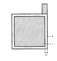
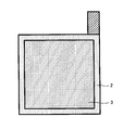
- FIG. 1 is a cross-sectional view illustrating a solid battery 10. It is a figure explaining the positive electrode collector 1 and the 1st insulating layer 2.
- FIG. It is a figure explaining the 1st insulating layer 2 and the positive electrode layer 3.
- FIG. It is a figure explaining the 2nd insulating layer 6 and the negative electrode collector 7.
- FIG. It is a figure explaining the negative electrode layer 5 and the 2nd insulating layer 6.
- the battery of the present invention is a lithium ion secondary battery
- the form shown below is an illustration of this invention and this invention is not limited to the form shown below.
- FIG. 1 is a cross-sectional view illustrating a solid battery 10 of the present invention
- FIGS. 2A to 2D are diagrams illustrating a manufacturing process of the solid battery 10.
- the stacking direction is the vertical direction of the paper surface of FIG. 1 and the back / front direction of the paper surface of FIGS. 2A to 2D.
- the solid battery 10 includes a positive electrode current collector 1, a positive electrode layer 3 formed on the surface of the positive electrode current collector 1, and a first insulation disposed on the outer periphery of the positive electrode layer 3.
- a layer 2 a solid electrolyte layer 4, a negative electrode layer 5 disposed on the opposite side of the positive electrode layer 3 with the solid electrolyte layer 4 in the center, and a second insulating layer 6 disposed on the outer periphery of the negative electrode layer 5.
- a negative electrode current collector 7 in contact with the negative electrode layer 5 and the second insulating layer 6, and a first laminate film 8 and a second laminate film 9 that enclose them.
- the stacking surfaces of the positive electrode current collector 1 and the negative electrode current collector 7, whose normal direction is the stacking direction of the positive electrode layer 3, the solid electrolyte layer 4, the negative electrode layer 5, and the like, have a size and shape. Are substantially the same.
- the solid battery 10 is manufactured through the following steps, for example.
- the first insulating layer 2 is formed on the outer edge of the positive electrode current collector 1 by a known method such as enamel coating or electrostatic coating.
- a masking material is disposed on the surface of the first insulating layer 2.
- a positive electrode slurry prepared by dispersing at least a positive electrode active material and a solid electrolyte in a solvent is applied to the entire surface of the positive electrode current collector 1 surrounded by the first insulating layer 2 by a known method such as a doctor blade method.
- the positive electrode layer 3 is formed as shown in FIG. 2B.
- the thickness of the positive electrode layer 3 is about several ⁇ m thicker than the thickness of the first insulating layer 2 (thickness in the back / front direction of FIG. 2B). To do.
- the first insulating layer 2 and the positive electrode layer 3 in this way, the first insulating layer 2 can be disposed on the outer periphery of the positive electrode layer 3.
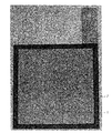
- a prototype of the positive electrode current collector 1 having the first insulating layer 2 formed on the outer edge is shown in FIG.
- the first insulating layer 2 shown in FIG. 3 has a thickness in the back / front direction of FIG. 3 of 25 ⁇ m.
- the second insulating layer 6 is formed on the outer edge of the negative electrode current collector 7 by a known method such as enamel coating or electrostatic coating.
- the width w2 of the second insulating layer 6 shown in FIG. 2C is narrower than the width w1 of the first insulating layer 2 shown in FIG. 2A.
- a masking material is disposed on the surface of the second insulating layer 6.
- a negative electrode slurry prepared by dispersing at least a negative electrode active material and a solid electrolyte in a solvent is applied to the entire surface of the negative electrode current collector 7 surrounded by the second insulating layer 6 by a known method such as a doctor blade method.
- a known method such as a doctor blade method.
- the negative electrode layer 5 is formed as shown in FIG. 2D.
- the thickness of the negative electrode layer 5 is about several ⁇ m thicker than the thickness of the second insulating layer 6 (thickness in the rear side / front side of FIG. 2D).
- FIG. 4 shows a prototype of the negative electrode current collector 7 in which the second insulating layer 6 is formed on the outer edge.
- the second insulating layer 6 shown in FIG. 4 has a thickness in the back / front direction of FIG. 4 of 25 ⁇ m.
- an electrolyte slurry prepared by dispersing at least a solid electrolyte in a solvent while the masking material is disposed on the surface of the second insulating layer 6 is used.
- the solid electrolyte layer 4 having the same size and shape of the laminated surface as that of the negative electrode layer 5 can be formed by applying to the surface by a known method such as a doctor blade method and volatilizing the solvent.
- the positive electrode layer 3 formed on the surface of the positive electrode current collector 1 surrounded by the first insulating layer 2 is disposed on the surface of the solid electrolyte layer 4, and the solid electrolyte layer 4 is A laminated body sandwiched between the positive electrode layer 3 and the negative electrode layer 5 is produced, and a predetermined compressive force is applied and pressed in the laminating direction of the laminated body. Thereafter, the pressed laminate is wrapped with the first laminate film 8 and the second laminate film 9. Next, the process of depressurizing (vacuum laminating) the space enclosed by the first laminate film 8 and the second laminate film 9 and thermally welding the outer edge 8a of the first laminate film 8 and the outer edge 9a of the second laminate film 9, for example. Through this, the solid battery 10 can be manufactured.
- the outer edge of the solid electrolyte layer 4 is located on the outer periphery (periphery) of the positive electrode layer 3 and the outer periphery (periphery) of the solid electrolyte layer 4 when viewed from the stacking direction.
- the outer edge of the first insulating layer 2 is located.
- the outer edge of the curved first insulating layer 2 and the end of the solid electrolyte layer 4 are in contact with each other over the entire circumference, and the positive electrode layer 3 and the A site X defined by the insulating layer 2 and the solid electrolyte layer 4 can be provided.
- the 1st insulating layer 2 which has adhered the site
- the thickness of the first insulating layer 2 is about several ⁇ m thinner than the thickness of the positive electrode layer 3, and the thickness of the second insulating layer 6 is about several ⁇ m thinner than the thickness of the negative electrode layer 5.
- the contact between the outer edge of the layer 2 and the outer edge of the second insulating layer 6 can be received, and as a result, the degree of bending of the negative electrode current collector 7 can be reduced.
- the degree to which the negative electrode current collector 7 is bent it is possible to prevent the solid electrolyte layer 4 from being broken at the boundary between the positive electrode layer 3 and the part X, which is the stress maximum part.
- the solid electrolyte layer 4 is cracked, when cracked from the positive electrode layer 3 side, it penetrates through a part of the positive electrode layer 3 that has entered the crack, and when cracked from the negative electrode layer 5 side, it enters the crack.
- the positive electrode layer 3 and the negative electrode layer 5 are connected via a part of the negative electrode layer 5 and short-circuited.
- the solid battery 10 it is possible to prevent the solid electrolyte layer 4 from being broken, so that a part of the positive electrode layer 3 and a part of the negative electrode layer 5 entering the crack of the solid electrolyte layer 4 are interposed. It becomes possible to prevent the short circuit.
- the positive electrode current collector 1 and the negative electrode current collector 7 can be made of a known conductive material that can be used as a positive electrode current collector or a negative electrode current collector of a lithium ion secondary battery.
- a conductive material include one or more elements selected from the group consisting of Cu, Ni, Al, V, Au, Pt, Mg, Fe, Ti, Co, Cr, Zn, Ge, and In. Examples of the metal material to be included can be given.
- the positive electrode collector 1 and the negative electrode collector 7 can be made into shapes, such as metal foil and a metal mesh, for example.
- the first insulating layer 2 and the second insulating layer 6 can be made of a known insulating material that can withstand the environment when the solid battery 10 is used.
- Examples of such an insulating material include polytetrafluoroethylene, polyamideimide, polypropylene (PP), and a mixture of two or more thereof.
- the well-known active material which can be contained in the positive electrode layer of a lithium ion secondary battery can be used suitably.
- examples of such a positive electrode active material include lithium cobaltate (LiCoO 2 ).
- the electrolyte contained in the positive electrode layer 3 a known electrolyte that can be contained in the positive electrode layer of the battery can be appropriately used.
- organic solid electrolytes such as polyethylene oxide can be exemplified.
- the positive electrode layer 3 may contain a binder for binding the positive electrode active material and the electrolyte and a conductive material for improving conductivity.
- Examples of the binder that can be contained in the positive electrode layer 3 include butylene rubber, and examples of the conductive material that can be contained in the positive electrode layer 3 include carbon black.
- a solvent used when manufacturing the positive electrode layer 3 the well-known solvent which can be used when adjusting the slurry used at the time of positive electrode layer preparation of a lithium ion secondary battery can be used suitably. As such a solvent, heptane and the like can be exemplified.
- examples of the electrolyte contained in the solid electrolyte layer 4 include the inorganic solid electrolyte and the organic solid electrolyte that can be contained in the positive electrode layer 3.
- the said solvent etc. which can be used when producing the positive electrode layer 3 can be illustrated.
- the negative electrode active material to be contained in the negative electrode layer 5 a known active material that can be contained in the negative electrode layer of the lithium ion secondary battery can be appropriately used. Examples of such an active material include graphite.
- the electrolyte contained in the negative electrode layer 5 a known electrolyte that can be contained in the negative electrode layer of the lithium ion secondary battery can be appropriately used. As such an electrolyte, the said inorganic solid electrolyte, organic solid electrolyte, etc. which can be contained in the positive electrode layer 3 can be illustrated.
- the negative electrode layer 5 may contain a binder for binding the negative electrode active material and the electrolyte, and a conductive material for improving conductivity.
- binder and conductive material that can be contained in the negative electrode layer 5 examples include the binder and conductive material that can be contained in the positive electrode layer 3. Moreover, as a solvent used when producing the negative electrode layer 5, the said solvent etc. which can be used when producing the positive electrode layer 3 can be illustrated.
- first laminate film 8 and the second laminate film 9 can withstand the environment when the lithium ion secondary battery is used, have a property of not allowing gas or liquid to permeate, and can be sealed. Can be used without any particular limitation.
- a film in which polypropylene (PP) is coated on the surface of aluminum can be exemplified.
- the first insulating layer 2 has a thickness that is about several ⁇ m thinner than the thickness of the positive electrode layer 3, but the solid state battery of the present invention is not limited to this form.
- the first insulating layer and the first electrode layer may have the same thickness, and the thickness of the first insulating layer is the first. It may be thicker than the thickness of the electrode layer.
- the thickness of the first insulating layer is from the viewpoint of making it easy to prevent a short circuit through a part of the electrode layer entering the crack of the solid electrolyte layer by making the solid electrolyte layer difficult to break. It is preferable that the thickness is equal to or less than the thickness of the first electrode layer.
- the first insulating layer 2 is disposed on the outer periphery of the positive electrode layer 3 and the second insulating layer 6 is disposed on the outer periphery of the negative electrode layer 5.
- the solid battery of the present invention is not limited to this form.
- the solid battery of the present invention may be configured such that the second insulating layer is not disposed on the outer periphery of the second electrode layer (the negative electrode layer 5 in the solid battery 10; the same applies hereinafter).
- the second insulating layer is disposed on the outer periphery of the second electrode layer. Is preferred.
- the solid battery of the present invention is not limited to this form.
- the second insulating layer and the second electrode layer may have the same thickness.
- the thickness may be larger than the thickness of the second electrode layer.
- the thickness of the second insulating layer is from the viewpoint of making it easy to prevent a short circuit through a part of the electrode layer entering the crack of the solid electrolyte layer by making the solid electrolyte layer difficult to break. It is preferable that the thickness is equal to or less than the thickness of the second electrode layer.
- the width of the second insulating layer 6 is made smaller than the width w1 of the first insulating layer 5 so that the size of the laminated surface of the negative electrode layer 5 is the same as that of the laminated surface of the positive electrode layer 3.
- the embodiment is illustrated in which the outer edge of the negative electrode layer 5 is located on the outer periphery of the positive electrode layer 3 when viewed from the stacking direction, and the solid state battery of the present invention is not limited to this form.
- the laminate surface of the positive electrode layer and the laminate surface of the negative electrode layer may be the same size, and the laminate surface of the positive electrode layer may be larger than the laminate surface of the negative electrode layer. is there.
- the size of the laminated surface of the negative electrode layer is made larger than the size of the laminated surface of the positive electrode layer
- the positive electrode layer and the negative electrode layer are preferably arranged so that the outer edge of the negative electrode layer is positioned on the outer periphery of the positive electrode layer when viewed from the stacking direction.
- the solid battery 10 which is a lithium ion secondary battery is illustrated, but the solid battery of the present invention is not limited to this form.
- the solid state battery of the present invention may be configured such that ions other than lithium ions move between the first electrode layer and the second electrode layer. Examples of such ions include sodium ions and potassium ions.
- the positive electrode active material, the solid electrolyte, and the negative electrode active material may be appropriately selected according to the moving ions.
Landscapes
- Chemical & Material Sciences (AREA)
- Engineering & Computer Science (AREA)
- Electrochemistry (AREA)
- General Chemical & Material Sciences (AREA)
- Chemical Kinetics & Catalysis (AREA)
- Manufacturing & Machinery (AREA)
- Materials Engineering (AREA)
- Physics & Mathematics (AREA)
- Condensed Matter Physics & Semiconductors (AREA)
- Dispersion Chemistry (AREA)
- General Physics & Mathematics (AREA)
- Inorganic Chemistry (AREA)
- Secondary Cells (AREA)
- Primary Cells (AREA)
Abstract
Description
本発明は、第1電極層及び第2電極層、並びに、第1電極層及び第2電極層の間に配設された固体電解質層を備える固体電池であって、第1電極層の外周に第1絶縁層が配設され、第1電極層、固体電解質層、及び、第2電極層の積層方向を法線方向とする積層面の大きさは、第1電極層が固体電解質層よりも小さく、積層方向から見た時に、第1電極層の外周に固体電解質層の外縁が位置し、且つ、固体電解質層の外周に第1絶縁層の外縁が位置し、第1絶縁層の外縁と固体電解質層の端部とが接触するように、第1電極層、第1絶縁層、及び、固体電解質層が配設されていることを特徴とする、固体電池である。
2…第1絶縁層
3…正極層(第1電極層)
4…固体電解質層(電解質層)
5…負極層(第2電極層)
6…第2絶縁層
7…負極集電体
8…第1ラミネートフィルム
9…第2ラミネートフィルム
10…固体電池
Claims (5)
- 第1電極層及び第2電極層、並びに、前記第1電極層及び前記第2電極層の間に配設された固体電解質層を備える固体電池であって、
前記第1電極層の外周に第1絶縁層が配設され、
前記第1電極層、前記固体電解質層、及び、前記第2電極層の積層方向を法線方向とする積層面の大きさは、前記第1電極層が前記固体電解質層よりも小さく、
前記積層方向から見た時に、前記第1電極層の外周に前記固体電解質層の外縁が位置し、且つ、前記固体電解質層の外周に前記第1絶縁層の外縁が位置し、
前記第1絶縁層の外縁と前記固体電解質層の端部とが接触するように、前記第1電極層、前記第1絶縁層、及び、前記固体電解質層が配設されていることを特徴とする、固体電池。 - 前記第1絶縁層の厚さは、前記第1電極層の厚さ以下であることを特徴とする、請求項1に記載の固体電池。
- 前記第2電極層の外周に、さらに第2絶縁層が配設されていることを特徴とする、請求項1又は2に記載の固体電池。
- 前記第2絶縁層の厚さは、前記第2電極層の厚さ以下であることを特徴とする、請求項3に記載の固体電池。
- 前記第2電極層の前記積層面の大きさは前記第1電極層の前記積層面の大きさよりも大きく、且つ、前記積層方向から見た時に、前記第1電極層の外周に前記第2電極層の外縁が位置していることを特徴とする、請求項1~4のいずれか1項に記載の固体電池。
Priority Applications (4)
| Application Number | Priority Date | Filing Date | Title |
|---|---|---|---|
| CN201180066013.3A CN103620856B (zh) | 2011-02-24 | 2011-02-24 | 固体电池 |
| US13/993,479 US9853274B2 (en) | 2011-02-24 | 2011-02-24 | Solid battery |
| PCT/JP2011/054155 WO2012114497A1 (ja) | 2011-02-24 | 2011-02-24 | 固体電池 |
| JP2013500787A JP5610057B2 (ja) | 2011-02-24 | 2011-02-24 | 固体電池 |
Applications Claiming Priority (1)
| Application Number | Priority Date | Filing Date | Title |
|---|---|---|---|
| PCT/JP2011/054155 WO2012114497A1 (ja) | 2011-02-24 | 2011-02-24 | 固体電池 |
Publications (1)
| Publication Number | Publication Date |
|---|---|
| WO2012114497A1 true WO2012114497A1 (ja) | 2012-08-30 |
Family
ID=46720314
Family Applications (1)
| Application Number | Title | Priority Date | Filing Date |
|---|---|---|---|
| PCT/JP2011/054155 Ceased WO2012114497A1 (ja) | 2011-02-24 | 2011-02-24 | 固体電池 |
Country Status (4)
| Country | Link |
|---|---|
| US (1) | US9853274B2 (ja) |
| JP (1) | JP5610057B2 (ja) |
| CN (1) | CN103620856B (ja) |
| WO (1) | WO2012114497A1 (ja) |
Cited By (13)
| Publication number | Priority date | Publication date | Assignee | Title |
|---|---|---|---|---|
| JP2014127463A (ja) * | 2012-12-27 | 2014-07-07 | Toyota Motor Corp | 全固体電池の製造方法 |
| JP2015069775A (ja) * | 2013-09-27 | 2015-04-13 | 株式会社村田製作所 | 全固体電池およびその製造方法 |
| JP2015076178A (ja) * | 2013-10-07 | 2015-04-20 | 古河機械金属株式会社 | 電気素子および電気素子の製造方法 |
| JP2016091750A (ja) * | 2014-11-04 | 2016-05-23 | 日立造船株式会社 | 全固体二次電池 |
| JP2016157576A (ja) * | 2015-02-24 | 2016-09-01 | 株式会社豊田自動織機 | 蓄電装置 |
| WO2017187494A1 (ja) * | 2016-04-26 | 2017-11-02 | 日立造船株式会社 | 全固体二次電池 |
| JP2018073816A (ja) * | 2016-10-13 | 2018-05-10 | 輝能科技股▲分▼有限公司Prologium Technology Co., Ltd. | 電池構造 |
| JP2019121532A (ja) * | 2018-01-09 | 2019-07-22 | トヨタ自動車株式会社 | 全固体電池 |
| CN111095660A (zh) * | 2017-09-13 | 2020-05-01 | 富士胶片株式会社 | 全固态二次电池、全固态二次电池用外装材料及全固态二次电池的制造方法 |
| JP2020135974A (ja) * | 2019-02-14 | 2020-08-31 | 日産自動車株式会社 | 全固体電池 |
| US11431023B2 (en) | 2018-12-17 | 2022-08-30 | Panasonic Intellectual Property Management Co., Ltd. | All-solid-state battery |
| US11476503B2 (en) | 2018-12-12 | 2022-10-18 | Panasonic Intellectual Property Management Co., Ltd. | All-solid-state battery |
| JP2025035842A (ja) * | 2023-09-04 | 2025-03-14 | トヨタ自動車株式会社 | 蓄電セル |
Families Citing this family (10)
| Publication number | Priority date | Publication date | Assignee | Title |
|---|---|---|---|---|
| DE102014222332A1 (de) * | 2014-10-31 | 2016-05-04 | Robert Bosch Gmbh | Schichtaufbau für ein galvanisches Element |
| CN106981621A (zh) | 2016-01-19 | 2017-07-25 | 株式会社杰士汤浅国际 | 负极板及其制造方法、蓄电元件及其制造方法 |
| JP6772855B2 (ja) * | 2017-01-20 | 2020-10-21 | トヨタ自動車株式会社 | 全固体電池 |
| JP6683165B2 (ja) * | 2017-04-05 | 2020-04-15 | トヨタ自動車株式会社 | 全固体電池の製造方法 |
| CN108933227B (zh) * | 2017-05-23 | 2020-06-09 | 辉能科技股份有限公司 | 电池结构 |
| CN111480260B (zh) * | 2018-03-02 | 2023-07-25 | 株式会社村田制作所 | 全固体电池 |
| JP6856042B2 (ja) * | 2018-03-06 | 2021-04-07 | トヨタ自動車株式会社 | 全固体電池 |
| CN114616706B (zh) * | 2019-10-25 | 2024-07-23 | 夏普株式会社 | 层叠电池及其制造方法 |
| CN115548460A (zh) * | 2021-06-29 | 2022-12-30 | 广汽埃安新能源汽车有限公司 | 叠片电芯结构制造方法及叠片电芯结构 |
| CN115513532A (zh) * | 2022-09-02 | 2022-12-23 | 中国第一汽车股份有限公司 | 一种防短路固态电池及其制备方法 |
Citations (4)
| Publication number | Priority date | Publication date | Assignee | Title |
|---|---|---|---|---|
| JPS59196576A (ja) * | 1983-04-20 | 1984-11-07 | Sanyo Electric Co Ltd | 固体電解質電池 |
| JPH07249403A (ja) * | 1994-03-11 | 1995-09-26 | Yuasa Corp | 積層型電池およびその製造方法 |
| JP2010092696A (ja) * | 2008-10-07 | 2010-04-22 | Nissan Motor Co Ltd | 非水電解質二次電池 |
| JP2010272368A (ja) * | 2009-05-21 | 2010-12-02 | Toyota Motor Corp | 固体電解質電池の製造方法 |
Family Cites Families (3)
| Publication number | Priority date | Publication date | Assignee | Title |
|---|---|---|---|---|
| CN1139142C (zh) | 1997-02-28 | 2004-02-18 | 旭化成株式会社 | 无水二次电池及其制造方法 |
| JP3813364B2 (ja) * | 1998-11-30 | 2006-08-23 | 三洋電機株式会社 | 薄型非水電解質電池及びその製造方法 |
| JP2003197474A (ja) * | 2001-12-28 | 2003-07-11 | Nec Tokin Corp | エネルギーデバイスおよびその製造方法 |
-
2011
- 2011-02-24 CN CN201180066013.3A patent/CN103620856B/zh active Active
- 2011-02-24 WO PCT/JP2011/054155 patent/WO2012114497A1/ja not_active Ceased
- 2011-02-24 US US13/993,479 patent/US9853274B2/en active Active
- 2011-02-24 JP JP2013500787A patent/JP5610057B2/ja active Active
Patent Citations (4)
| Publication number | Priority date | Publication date | Assignee | Title |
|---|---|---|---|---|
| JPS59196576A (ja) * | 1983-04-20 | 1984-11-07 | Sanyo Electric Co Ltd | 固体電解質電池 |
| JPH07249403A (ja) * | 1994-03-11 | 1995-09-26 | Yuasa Corp | 積層型電池およびその製造方法 |
| JP2010092696A (ja) * | 2008-10-07 | 2010-04-22 | Nissan Motor Co Ltd | 非水電解質二次電池 |
| JP2010272368A (ja) * | 2009-05-21 | 2010-12-02 | Toyota Motor Corp | 固体電解質電池の製造方法 |
Cited By (15)
| Publication number | Priority date | Publication date | Assignee | Title |
|---|---|---|---|---|
| JP2014127463A (ja) * | 2012-12-27 | 2014-07-07 | Toyota Motor Corp | 全固体電池の製造方法 |
| JP2015069775A (ja) * | 2013-09-27 | 2015-04-13 | 株式会社村田製作所 | 全固体電池およびその製造方法 |
| JP2015076178A (ja) * | 2013-10-07 | 2015-04-20 | 古河機械金属株式会社 | 電気素子および電気素子の製造方法 |
| JP2016091750A (ja) * | 2014-11-04 | 2016-05-23 | 日立造船株式会社 | 全固体二次電池 |
| JP2016157576A (ja) * | 2015-02-24 | 2016-09-01 | 株式会社豊田自動織機 | 蓄電装置 |
| WO2017187494A1 (ja) * | 2016-04-26 | 2017-11-02 | 日立造船株式会社 | 全固体二次電池 |
| JP2018073816A (ja) * | 2016-10-13 | 2018-05-10 | 輝能科技股▲分▼有限公司Prologium Technology Co., Ltd. | 電池構造 |
| CN111095660A (zh) * | 2017-09-13 | 2020-05-01 | 富士胶片株式会社 | 全固态二次电池、全固态二次电池用外装材料及全固态二次电池的制造方法 |
| US11670796B2 (en) | 2017-09-13 | 2023-06-06 | Fujifilm Corporation | All-solid state secondary battery, exterior material for all-solid state secondary battery, and method for manufacturing all-solid state secondary battery |
| JP2019121532A (ja) * | 2018-01-09 | 2019-07-22 | トヨタ自動車株式会社 | 全固体電池 |
| US11476503B2 (en) | 2018-12-12 | 2022-10-18 | Panasonic Intellectual Property Management Co., Ltd. | All-solid-state battery |
| US11431023B2 (en) | 2018-12-17 | 2022-08-30 | Panasonic Intellectual Property Management Co., Ltd. | All-solid-state battery |
| JP2020135974A (ja) * | 2019-02-14 | 2020-08-31 | 日産自動車株式会社 | 全固体電池 |
| JP7274300B2 (ja) | 2019-02-14 | 2023-05-16 | 日産自動車株式会社 | 全固体電池 |
| JP2025035842A (ja) * | 2023-09-04 | 2025-03-14 | トヨタ自動車株式会社 | 蓄電セル |
Also Published As
| Publication number | Publication date |
|---|---|
| US9853274B2 (en) | 2017-12-26 |
| JPWO2012114497A1 (ja) | 2014-07-07 |
| JP5610057B2 (ja) | 2014-10-22 |
| US20130323568A1 (en) | 2013-12-05 |
| CN103620856B (zh) | 2016-08-17 |
| CN103620856A (zh) | 2014-03-05 |
Similar Documents
| Publication | Publication Date | Title |
|---|---|---|
| JP5610057B2 (ja) | 固体電池 | |
| US9818996B2 (en) | Solid battery and method for manufacturing solid battery | |
| JP5720779B2 (ja) | バイポーラ全固体電池 | |
| JP5636965B2 (ja) | リチウムイオン二次電池用電極体の製造方法、及びリチウムイオン二次電池の製造方法 | |
| KR101473145B1 (ko) | 전극 조립체, 전지셀, 전극 조립체의 제조방법 및 전지셀의 제조 방법 | |
| JP5413129B2 (ja) | 固体電池の製造方法 | |
| WO2017057762A1 (ja) | リチウムイオン二次電池の電極部、リチウムイオン二次電池及びリチウムイオン二次電池の製造方法 | |
| CN105322195A (zh) | 全固体电池的制造方法和全固体电池 | |
| JP2019192564A (ja) | 全固体電池 | |
| CN103688403A (zh) | 固体电池的制造方法 | |
| JP2013243004A (ja) | 固体電池、及び固体電池の製造方法 | |
| JP2014102982A (ja) | 全固体電池及びその製造方法 | |
| JP2013093216A (ja) | 電池 | |
| JP5343663B2 (ja) | 双極型二次電池の製造方法および製造装置 | |
| JP2025061361A (ja) | 電池ケースおよび電池 | |
| KR102069512B1 (ko) | 2종의 분리막을 사용한 전극조립체 | |
| CN114335750A (zh) | 非水电解液二次电池 | |
| JP6681017B2 (ja) | 電極体を有する二次電池 | |
| CN114914518B (zh) | 非水电解液二次电池 | |
| JP2012248294A (ja) | 電池 | |
| JP7158449B2 (ja) | 非水電解液二次電池 | |
| CN114725526A (zh) | 非水电解液二次电池 | |
| JP2013084358A (ja) | 電池の製造方法 | |
| JP2013030357A (ja) | 電池の製造方法 | |
| CN118738713A (zh) | 薄型层叠电池 |
Legal Events
| Date | Code | Title | Description |
|---|---|---|---|
| 121 | Ep: the epo has been informed by wipo that ep was designated in this application |
Ref document number: 11859145 Country of ref document: EP Kind code of ref document: A1 |
|
| ENP | Entry into the national phase |
Ref document number: 2013500787 Country of ref document: JP Kind code of ref document: A |
|
| WWE | Wipo information: entry into national phase |
Ref document number: 13993479 Country of ref document: US |
|
| NENP | Non-entry into the national phase |
Ref country code: DE |
|
| 122 | Ep: pct application non-entry in european phase |
Ref document number: 11859145 Country of ref document: EP Kind code of ref document: A1 |