WO2012111480A1 - 導電性ペースト及び太陽電池 - Google Patents
導電性ペースト及び太陽電池 Download PDFInfo
- Publication number
- WO2012111480A1 WO2012111480A1 PCT/JP2012/052708 JP2012052708W WO2012111480A1 WO 2012111480 A1 WO2012111480 A1 WO 2012111480A1 JP 2012052708 W JP2012052708 W JP 2012052708W WO 2012111480 A1 WO2012111480 A1 WO 2012111480A1
- Authority
- WO
- WIPO (PCT)
- Prior art keywords
- solvent
- conductive paste
- conductive
- electrode
- semiconductor substrate
- Prior art date
Links
- 239000002904 solvent Substances 0.000 claims abstract description 106
- 239000000843 powder Substances 0.000 claims abstract description 46
- 239000011347 resin Substances 0.000 claims abstract description 42
- 229920005989 resin Polymers 0.000 claims abstract description 42
- 229910052739 hydrogen Inorganic materials 0.000 claims abstract description 37
- 239000001257 hydrogen Substances 0.000 claims abstract description 37
- 239000011230 binding agent Substances 0.000 claims abstract description 35
- 239000011521 glass Substances 0.000 claims abstract description 29
- 125000002887 hydroxy group Chemical group [H]O* 0.000 claims abstract description 23
- 125000003262 carboxylic acid ester group Chemical group [H]C([H])([*:2])OC(=O)C([H])([H])[*:1] 0.000 claims abstract description 17
- RUOJZAUFBMNUDX-UHFFFAOYSA-N propylene carbonate Chemical compound CC1COC(=O)O1 RUOJZAUFBMNUDX-UHFFFAOYSA-N 0.000 claims abstract description 14
- 239000004065 semiconductor Substances 0.000 claims description 69
- 239000000758 substrate Substances 0.000 claims description 53
- 238000007639 printing Methods 0.000 claims description 18
- QVGXLLKOCUKJST-UHFFFAOYSA-N atomic oxygen Chemical compound [O] QVGXLLKOCUKJST-UHFFFAOYSA-N 0.000 claims description 14
- 229910052760 oxygen Inorganic materials 0.000 claims description 14
- 239000001301 oxygen Substances 0.000 claims description 14
- BGHCVCJVXZWKCC-UHFFFAOYSA-N tetradecane Chemical compound CCCCCCCCCCCCCC BGHCVCJVXZWKCC-UHFFFAOYSA-N 0.000 claims description 14
- OKTJSMMVPCPJKN-UHFFFAOYSA-N Carbon Chemical compound [C] OKTJSMMVPCPJKN-UHFFFAOYSA-N 0.000 claims description 13
- 229910052799 carbon Inorganic materials 0.000 claims description 13
- RRQYJINTUHWNHW-UHFFFAOYSA-N 1-ethoxy-2-(2-ethoxyethoxy)ethane Chemical compound CCOCCOCCOCC RRQYJINTUHWNHW-UHFFFAOYSA-N 0.000 claims description 7
- YCOZIPAWZNQLMR-UHFFFAOYSA-N heptane - octane Natural products CCCCCCCCCCCCCCC YCOZIPAWZNQLMR-UHFFFAOYSA-N 0.000 claims description 7
- 150000001733 carboxylic acid esters Chemical class 0.000 claims description 4
- HYLLZXPMJRMUHH-UHFFFAOYSA-N 1-[2-(2-methoxyethoxy)ethoxy]butane Chemical compound CCCCOCCOCCOC HYLLZXPMJRMUHH-UHFFFAOYSA-N 0.000 claims description 3
- SNAQINZKMQFYFV-UHFFFAOYSA-N 1-[2-[2-(2-methoxyethoxy)ethoxy]ethoxy]butane Chemical compound CCCCOCCOCCOCCOC SNAQINZKMQFYFV-UHFFFAOYSA-N 0.000 claims description 3
- 229940019778 diethylene glycol diethyl ether Drugs 0.000 claims description 3
- 230000000149 penetrating effect Effects 0.000 claims description 3
- 238000005245 sintering Methods 0.000 claims description 2
- DAFHKNAQFPVRKR-UHFFFAOYSA-N (3-hydroxy-2,2,4-trimethylpentyl) 2-methylpropanoate Chemical compound CC(C)C(O)C(C)(C)COC(=O)C(C)C DAFHKNAQFPVRKR-UHFFFAOYSA-N 0.000 abstract description 11
- 238000006243 chemical reaction Methods 0.000 description 27
- 239000003960 organic solvent Substances 0.000 description 15
- 238000000034 method Methods 0.000 description 14
- 238000002156 mixing Methods 0.000 description 10
- 238000012856 packing Methods 0.000 description 10
- 239000012046 mixed solvent Substances 0.000 description 6
- 239000000203 mixture Substances 0.000 description 6
- UDSFAEKRVUSQDD-UHFFFAOYSA-N Dimethyl adipate Chemical compound COC(=O)CCCCC(=O)OC UDSFAEKRVUSQDD-UHFFFAOYSA-N 0.000 description 5
- 238000007650 screen-printing Methods 0.000 description 5
- 230000015572 biosynthetic process Effects 0.000 description 4
- 230000002349 favourable effect Effects 0.000 description 4
- 239000001856 Ethyl cellulose Substances 0.000 description 3
- ZZSNKZQZMQGXPY-UHFFFAOYSA-N Ethyl cellulose Chemical compound CCOCC1OC(OC)C(OCC)C(OCC)C1OC1C(O)C(O)C(OC)C(CO)O1 ZZSNKZQZMQGXPY-UHFFFAOYSA-N 0.000 description 3
- 239000002253 acid Substances 0.000 description 3
- 235000014113 dietary fatty acids Nutrition 0.000 description 3
- 239000006185 dispersion Substances 0.000 description 3
- 238000004090 dissolution Methods 0.000 description 3
- 150000002148 esters Chemical class 0.000 description 3
- 229920001249 ethyl cellulose Polymers 0.000 description 3
- 235000019325 ethyl cellulose Nutrition 0.000 description 3
- 239000000194 fatty acid Substances 0.000 description 3
- 229930195729 fatty acid Natural products 0.000 description 3
- 150000004665 fatty acids Chemical class 0.000 description 3
- 238000010304 firing Methods 0.000 description 3
- 239000011810 insulating material Substances 0.000 description 3
- 239000012454 non-polar solvent Substances 0.000 description 3
- 239000002245 particle Substances 0.000 description 3
- 239000002798 polar solvent Substances 0.000 description 3
- 239000003981 vehicle Substances 0.000 description 3
- WUOACPNHFRMFPN-SECBINFHSA-N (S)-(-)-alpha-terpineol Chemical compound CC1=CC[C@@H](C(C)(C)O)CC1 WUOACPNHFRMFPN-SECBINFHSA-N 0.000 description 2
- RSWGJHLUYNHPMX-UHFFFAOYSA-N Abietic-Saeure Natural products C12CCC(C(C)C)=CC2=CCC2C1(C)CCCC2(C)C(O)=O RSWGJHLUYNHPMX-UHFFFAOYSA-N 0.000 description 2
- UFHFLCQGNIYNRP-UHFFFAOYSA-N Hydrogen Chemical compound [H][H] UFHFLCQGNIYNRP-UHFFFAOYSA-N 0.000 description 2
- KHPCPRHQVVSZAH-HUOMCSJISA-N Rosin Natural products O(C/C=C/c1ccccc1)[C@H]1[C@H](O)[C@@H](O)[C@@H](O)[C@@H](CO)O1 KHPCPRHQVVSZAH-HUOMCSJISA-N 0.000 description 2
- 229910052581 Si3N4 Inorganic materials 0.000 description 2
- OVKDFILSBMEKLT-UHFFFAOYSA-N alpha-Terpineol Natural products CC(=C)C1(O)CCC(C)=CC1 OVKDFILSBMEKLT-UHFFFAOYSA-N 0.000 description 2
- 229940088601 alpha-terpineol Drugs 0.000 description 2
- 230000000052 comparative effect Effects 0.000 description 2
- 238000000354 decomposition reaction Methods 0.000 description 2
- 230000006866 deterioration Effects 0.000 description 2
- DOIRQSBPFJWKBE-UHFFFAOYSA-N dibutyl phthalate Chemical compound CCCCOC(=O)C1=CC=CC=C1C(=O)OCCCC DOIRQSBPFJWKBE-UHFFFAOYSA-N 0.000 description 2
- JXTHNDFMNIQAHM-UHFFFAOYSA-N dichloroacetic acid Chemical compound OC(=O)C(Cl)Cl JXTHNDFMNIQAHM-UHFFFAOYSA-N 0.000 description 2
- 230000002209 hydrophobic effect Effects 0.000 description 2
- 239000002184 metal Substances 0.000 description 2
- 229910052751 metal Inorganic materials 0.000 description 2
- 229910021421 monocrystalline silicon Inorganic materials 0.000 description 2
- 239000011368 organic material Substances 0.000 description 2
- 238000000623 plasma-assisted chemical vapour deposition Methods 0.000 description 2
- 238000000518 rheometry Methods 0.000 description 2
- HQVNEWCFYHHQES-UHFFFAOYSA-N silicon nitride Chemical compound N12[Si]34N5[Si]62N3[Si]51N64 HQVNEWCFYHHQES-UHFFFAOYSA-N 0.000 description 2
- KHPCPRHQVVSZAH-UHFFFAOYSA-N trans-cinnamyl beta-D-glucopyranoside Natural products OC1C(O)C(O)C(CO)OC1OCC=CC1=CC=CC=C1 KHPCPRHQVVSZAH-UHFFFAOYSA-N 0.000 description 2
- ZXUOFCUEFQCKKH-UHFFFAOYSA-N 12-methyltridecan-1-ol Chemical compound CC(C)CCCCCCCCCCCO ZXUOFCUEFQCKKH-UHFFFAOYSA-N 0.000 description 1
- OAYXUHPQHDHDDZ-UHFFFAOYSA-N 2-(2-butoxyethoxy)ethanol Chemical compound CCCCOCCOCCO OAYXUHPQHDHDDZ-UHFFFAOYSA-N 0.000 description 1
- VXQBJTKSVGFQOL-UHFFFAOYSA-N 2-(2-butoxyethoxy)ethyl acetate Chemical compound CCCCOCCOCCOC(C)=O VXQBJTKSVGFQOL-UHFFFAOYSA-N 0.000 description 1
- 229910018072 Al 2 O 3 Inorganic materials 0.000 description 1
- 229910015902 Bi 2 O 3 Inorganic materials 0.000 description 1
- 239000004803 Di-2ethylhexylphthalate Substances 0.000 description 1
- 239000000020 Nitrocellulose Substances 0.000 description 1
- 229910004298 SiO 2 Inorganic materials 0.000 description 1
- VYPSYNLAJGMNEJ-UHFFFAOYSA-N Silicium dioxide Chemical compound O=[Si]=O VYPSYNLAJGMNEJ-UHFFFAOYSA-N 0.000 description 1
- 235000021355 Stearic acid Nutrition 0.000 description 1
- GWEVSGVZZGPLCZ-UHFFFAOYSA-N Titan oxide Chemical compound O=[Ti]=O GWEVSGVZZGPLCZ-UHFFFAOYSA-N 0.000 description 1
- 229910052784 alkaline earth metal Inorganic materials 0.000 description 1
- 150000001342 alkaline earth metals Chemical class 0.000 description 1
- 125000003368 amide group Chemical group 0.000 description 1
- 238000013528 artificial neural network Methods 0.000 description 1
- 239000012298 atmosphere Substances 0.000 description 1
- BJQHLKABXJIVAM-UHFFFAOYSA-N bis(2-ethylhexyl) phthalate Chemical compound CCCCC(CC)COC(=O)C1=CC=CC=C1C(=O)OCC(CC)CCCC BJQHLKABXJIVAM-UHFFFAOYSA-N 0.000 description 1
- SCABKEBYDRTODC-UHFFFAOYSA-N bis[2-(2-butoxyethoxy)ethyl] hexanedioate Chemical compound CCCCOCCOCCOC(=O)CCCCC(=O)OCCOCCOCCCC SCABKEBYDRTODC-UHFFFAOYSA-N 0.000 description 1
- -1 carboxylate ester Chemical class 0.000 description 1
- 150000001732 carboxylic acid derivatives Chemical group 0.000 description 1
- 239000004359 castor oil Substances 0.000 description 1
- 235000019438 castor oil Nutrition 0.000 description 1
- 229920006217 cellulose acetate butyrate Polymers 0.000 description 1
- 238000002485 combustion reaction Methods 0.000 description 1
- 239000004020 conductor Substances 0.000 description 1
- 239000013078 crystal Substances 0.000 description 1
- 229910021419 crystalline silicon Inorganic materials 0.000 description 1
- 230000007423 decrease Effects 0.000 description 1
- 230000001419 dependent effect Effects 0.000 description 1
- 239000002270 dispersing agent Substances 0.000 description 1
- 230000000694 effects Effects 0.000 description 1
- 239000000839 emulsion Substances 0.000 description 1
- 230000007613 environmental effect Effects 0.000 description 1
- 125000004185 ester group Chemical group 0.000 description 1
- 238000011156 evaluation Methods 0.000 description 1
- 238000000605 extraction Methods 0.000 description 1
- 238000011049 filling Methods 0.000 description 1
- ZEMPKEQAKRGZGQ-XOQCFJPHSA-N glycerol triricinoleate Natural products CCCCCC[C@@H](O)CC=CCCCCCCCC(=O)OC[C@@H](COC(=O)CCCCCCCC=CC[C@@H](O)CCCCCC)OC(=O)CCCCCCCC=CC[C@H](O)CCCCCC ZEMPKEQAKRGZGQ-XOQCFJPHSA-N 0.000 description 1
- 230000001771 impaired effect Effects 0.000 description 1
- 239000012535 impurity Substances 0.000 description 1
- 230000003993 interaction Effects 0.000 description 1
- 230000001788 irregular Effects 0.000 description 1
- 150000002576 ketones Chemical class 0.000 description 1
- 238000004898 kneading Methods 0.000 description 1
- 238000004519 manufacturing process Methods 0.000 description 1
- 239000000463 material Substances 0.000 description 1
- 239000011812 mixed powder Substances 0.000 description 1
- 229920001220 nitrocellulos Polymers 0.000 description 1
- QIQXTHQIDYTFRH-UHFFFAOYSA-N octadecanoic acid Chemical compound CCCCCCCCCCCCCCCCCC(O)=O QIQXTHQIDYTFRH-UHFFFAOYSA-N 0.000 description 1
- OQCDKBAXFALNLD-UHFFFAOYSA-N octadecanoic acid Natural products CCCCCCCC(C)CCCCCCCCC(O)=O OQCDKBAXFALNLD-UHFFFAOYSA-N 0.000 description 1
- 125000002347 octyl group Chemical group [H]C([*])([H])C([H])([H])C([H])([H])C([H])([H])C([H])([H])C([H])([H])C([H])([H])C([H])([H])[H] 0.000 description 1
- WXZMFSXDPGVJKK-UHFFFAOYSA-N pentaerythritol Chemical compound OCC(CO)(CO)CO WXZMFSXDPGVJKK-UHFFFAOYSA-N 0.000 description 1
- 239000004014 plasticizer Substances 0.000 description 1
- 229910021420 polycrystalline silicon Inorganic materials 0.000 description 1
- 238000002360 preparation method Methods 0.000 description 1
- 238000007665 sagging Methods 0.000 description 1
- 229910052814 silicon oxide Inorganic materials 0.000 description 1
- 239000004071 soot Substances 0.000 description 1
- 238000003892 spreading Methods 0.000 description 1
- 239000008117 stearic acid Substances 0.000 description 1
- 238000003756 stirring Methods 0.000 description 1
- 239000000126 substance Substances 0.000 description 1
- 239000012756 surface treatment agent Substances 0.000 description 1
- 229920002803 thermoplastic polyurethane Polymers 0.000 description 1
- 239000002562 thickening agent Substances 0.000 description 1
- 239000013008 thixotropic agent Substances 0.000 description 1
- OGIDPMRJRNCKJF-UHFFFAOYSA-N titanium oxide Inorganic materials [Ti]=O OGIDPMRJRNCKJF-UHFFFAOYSA-N 0.000 description 1
- 238000005303 weighing Methods 0.000 description 1
Images


Classifications
-
- H—ELECTRICITY
- H01—ELECTRIC ELEMENTS
- H01L—SEMICONDUCTOR DEVICES NOT COVERED BY CLASS H10
- H01L31/00—Semiconductor devices sensitive to infrared radiation, light, electromagnetic radiation of shorter wavelength or corpuscular radiation and specially adapted either for the conversion of the energy of such radiation into electrical energy or for the control of electrical energy by such radiation; Processes or apparatus specially adapted for the manufacture or treatment thereof or of parts thereof; Details thereof
- H01L31/02—Details
- H01L31/0224—Electrodes
- H01L31/022408—Electrodes for devices characterised by at least one potential jump barrier or surface barrier
- H01L31/022425—Electrodes for devices characterised by at least one potential jump barrier or surface barrier for solar cells
-
- H—ELECTRICITY
- H01—ELECTRIC ELEMENTS
- H01B—CABLES; CONDUCTORS; INSULATORS; SELECTION OF MATERIALS FOR THEIR CONDUCTIVE, INSULATING OR DIELECTRIC PROPERTIES
- H01B1/00—Conductors or conductive bodies characterised by the conductive materials; Selection of materials as conductors
- H01B1/20—Conductive material dispersed in non-conductive organic material
- H01B1/22—Conductive material dispersed in non-conductive organic material the conductive material comprising metals or alloys
-
- Y—GENERAL TAGGING OF NEW TECHNOLOGICAL DEVELOPMENTS; GENERAL TAGGING OF CROSS-SECTIONAL TECHNOLOGIES SPANNING OVER SEVERAL SECTIONS OF THE IPC; TECHNICAL SUBJECTS COVERED BY FORMER USPC CROSS-REFERENCE ART COLLECTIONS [XRACs] AND DIGESTS
- Y02—TECHNOLOGIES OR APPLICATIONS FOR MITIGATION OR ADAPTATION AGAINST CLIMATE CHANGE
- Y02E—REDUCTION OF GREENHOUSE GAS [GHG] EMISSIONS, RELATED TO ENERGY GENERATION, TRANSMISSION OR DISTRIBUTION
- Y02E10/00—Energy generation through renewable energy sources
- Y02E10/50—Photovoltaic [PV] energy
Definitions
- the present invention relates to a conductive paste and a solar cell, and more particularly to a conductive paste suitable for forming an electrode of a solar cell, and a solar cell manufactured using this conductive paste.
- a solar cell usually has a light-receiving surface electrode of a predetermined pattern formed on one main surface of a semiconductor substrate. Further, an antireflection film is formed on the semiconductor substrate excluding the light receiving surface electrode, and the reflection loss of incident sunlight is suppressed by the antireflection film, thereby converting the conversion efficiency of sunlight into electric energy. Has improved.
- the light receiving surface electrode is usually formed as follows using a conductive paste. That is, the conductive paste contains conductive powder, glass frit, and an organic vehicle including at least a binder resin and a solvent. Then, a conductive paste is applied to the surface of the antireflection film formed on the semiconductor substrate to form a conductive film having a predetermined pattern. Next, the glass frit is melted in the baking process, and the antireflection film under the conductive film is decomposed and removed, whereby the conductive film is sintered to form a light receiving surface electrode, and the light receiving surface electrode and the semiconductor substrate are bonded together. They are bonded to make them both conductive.
- a conductive paste contains conductive powder, glass frit, and an organic vehicle including at least a binder resin and a solvent. Then, a conductive paste is applied to the surface of the antireflection film formed on the semiconductor substrate to form a conductive film having a predetermined pattern. Next, the glass frit is melted in the baking process, and the
- This method of disassembling and removing the antireflection film in the firing process and bonding the semiconductor substrate and the light-receiving surface electrode is called fire-through, and the conversion efficiency of the solar cell is greatly increased in fire-through performance.
- Dependent That is, it is known that if the fire-through property is insufficient, the conversion efficiency is lowered and the basic performance as a solar cell is inferior. For this reason, techniques for improving the fire-through performance have been actively researched and developed.
- Patent Document 1 As a glass composition, Bi 2 O 3 : 73.1 to 90%, B 2 O 3 : 2 to 14.5%, ZnO: 0 to 25 in terms of mass% in terms of oxide. %, MgO + CaO + SrO + BaO 2: 0.2 to 20%, SiO 2 + Al 2 O 3 : 0 to 8.5%, a glass composition for electrode formation has been proposed.
- the electrode forming conductive paste includes a metal powder such as Ag, a glass powder made of the above-described electrode forming glass composition, a binder resin such as ethyl cellulose resin, ⁇ -terpineol, propylene carbonate, and the like. It contains an organic vehicle composed of an arbitrary organic solvent, and by setting the glass component to the above-described composition range, a glass composition for electrode formation having good fire-through property and excellent thermal stability is obtained. ing.
- Patent Document 2 one or more kinds of conductive powder and one or more kinds of glass frit are dispersed in an organic solvent, and the organic solvent contains bis (2- (2butoxyethoxy) ethyl) adipate, two A thick film conductor containing at least one selected from the group consisting of basic acid ester, octyl epoxytalate, isotetradecanol, and hydrogenated rosin pentaerythritol has been proposed.
- JP 2010-83748 A (Claim 1, paragraph numbers [0044], [0053], etc.) International Publication No. 2009/146398 (Claim 1, Tables 9 and 10)
- a conductive paste for electrode formation of a solar cell usually contains a conductive powder, glass frit (glass powder), and an organic vehicle containing at least a binder resin and a solvent. Since the solvent needs to dissolve the binder resin, an organic material having a polar group such as a carboxylic acid ester group or a hydroxyl group is usually used in consideration of the solubility of the binder resin.
- Patent Document 1 suggests the possibility of using an organic solvent having a non-polar group such as propylene carbonate, but the organic solvent having a non-polar group is inferior in solubility in a binder resin, so that it is made into a paste. However, it is difficult to produce a desired conductive paste. Therefore, in Patent Document 1, an organic material having a polar group is actually used, and an example using ⁇ -terpineol is described.
- Patent Document 2 uses a specific organic solvent containing a polar hydroxyl group as a paste. That is, Patent Document 2 describes an example in which a specific organic solvent such as a dibasic acid ester and an organic solvent having two or more types of polar groups such as texanol are mixed to form a paste.
- a specific organic solvent such as a dibasic acid ester and an organic solvent having two or more types of polar groups such as texanol are mixed to form a paste.
- Patent Document 1 when only an organic solvent having a polar group is used as in Patent Document 1 and Patent Document 2, there are the following problems.
- the inorganic component conductive powder, glass frit, etc.
- the inorganic component is generated by Coulomb force or hydrogen bonding via the organic solvent.
- a pattern emulsion mask hereinafter simply referred to as “mask”
- liquidity of the inorganic component with respect to a pattern or a semiconductor substrate will fall.
- the conductive paste may adhere to the mask and cause clogging of the plate, which may cause deterioration of so-called plate slippage. Furthermore, since the fluidity of the inorganic component with respect to the semiconductor substrate is reduced, the packing property (fillability) of the inorganic component along the micro uneven structure on the surface of the semiconductor substrate may be reduced.
- This invention is made
- the printing paste is favorable and the electroconductive paste for electrode formation of a solar cell with favorable battery characteristics, and the sun manufactured using this electroconductive paste
- An object is to provide a battery.
- the present inventor has a solvent having a carboxylic acid ester group or a hydroxyl group which is a polar group (hereinafter also referred to as “polar solvent”) and a solvent having no such polar group (hereinafter also referred to as “nonpolar solvent”). And the polarity of the mixed solvent was lowered to such an extent that the binder resin did not cause poor dissolution. As a result, by using a mixed solvent in which a nonpolar solvent having a hydrogen bond term of Hansen solubility parameter of 7 (J / cm 3 ) 1/2 or less is mixed with a polar solvent, the occurrence of plate clogging is suppressed. As a result, it has been found that the printability is improved by improving the plate slippage. In addition, the inventors have obtained the knowledge that the fluidity of the inorganic component to the semiconductor substrate is improved, the packing property is improved, and the battery characteristics of the solar cell are also improved.
- the conductive paste according to the present invention is a conductive paste for printing and forming an electrode of a solar cell, and includes conductive powder, glass frit, A binder resin and a solvent, wherein the solvent contains a first solvent containing at least one of a carboxylic acid ester group and a hydroxyl group, and does not contain the carboxylic acid ester and the hydroxyl group, and has a Hansen solubility parameter of hydrogen. And a second solvent having a bond term of 7 (J / cm 3 ) 1/2 or less.
- the adhesiveness of the pattern to the mask or mesh is moderately reduced during printing, so the fluidity to the pattern is increased without impairing the solubility in the binder resin, and the discharge rate to the pattern also increases.
- plate clogging is less likely to occur, and the plate slippage is improved.
- liquidity of the inorganic component to a semiconductor substrate also increases, the packing property of the inorganic component with respect to the semiconductor substrate surface improves, As a result, a fire through property improves and it can improve conversion efficiency.
- the second solvent is diethylene glycol butyl methyl ether (hereinafter referred to as “DEGBME”), triethylene glycol butyl methyl ether (hereinafter referred to as “TEGBME”), diethylene glycol diethyl ether. (Hereinafter referred to as “DEGDEE”), propylene carbonate, and at least one selected from n-tetradecane are preferable.
- DEGBME diethylene glycol butyl methyl ether
- TEGBME triethylene glycol butyl methyl ether
- DEGDEE diethylene glycol diethyl ether
- propylene carbonate and at least one selected from n-tetradecane are preferable.
- the use of a solvent having a molar ratio of the oxygen component to the carbon component in the molecular structure of 0.3 or more as the second solvent does not impair the printability.
- the fire-through property can be further improved.
- solvents other than n-tetradecane are suitable as the second solvent.
- the second solvent has at least an oxygen component and a carbon component in the molecular structure, and a molar ratio of the oxygen component to the carbon component is 0.3 or more. .
- the second solvent contains at least one selected from DEGBME, TEGBME, DEGDEEE, and propylene carbonate.
- the first solvent includes texanol, dimethyl adipate, butyl carbitol acetate (hereinafter referred to as “BCA”), and butyl carbitol (hereinafter referred to as “BC”). It is preferable to include at least one selected from the group consisting of
- the present invention is particularly effective in the case of a conductive powder having hydrophilicity.
- the conductive paste of the present invention is preferably surface-treated so that the conductive powder becomes hydrophilic.
- the conductive powder is preferably Ag powder.
- the glass frit does not contain lead.
- an antireflection film and an electrode penetrating the antireflection film are formed on one main surface of the semiconductor substrate, and the conductive paste according to any one of the above is sintered. It is characterized by being made.
- the conductive paste of the present invention contains conductive powder such as Ag powder, preferably lead-free glass frit containing no lead, a binder resin, and a solvent, and the solvent is a carboxylic acid.
- conductive powder such as Ag powder, preferably lead-free glass frit containing no lead, a binder resin, and a solvent
- the solvent is a carboxylic acid.
- One or more kinds of first solvents for example, texanol, dimethyl adipate, BCA, BC) containing at least one of an ester group and a hydroxyl group, and hydrogen having a Hansen solubility parameter not containing the carboxylate ester and the hydroxyl group
- the conductive paste contains one or more second solvents (for example, DEGBME, TEGBME, DEGDEEE, propylene carbonate, n-tetradecane, etc.) having a bond term of 7 (J / cm 3 ) 1/2 or less.
- the adhesion of the pattern to the mask or mesh is moderately lowered during printing.
- liquidity with respect to a pattern increases without impairing the solubility with respect to binder resin, the discharge amount to a pattern also increases, plate
- liquidity of the inorganic component to a semiconductor substrate also increases, the packing property of the inorganic component with respect to the semiconductor substrate surface improves, As a result, a fire through property improves and it can improve conversion efficiency.
- an antireflection film and an electrode penetrating the antireflection film are formed on one main surface of the semiconductor substrate, and the electrode has the conductivity described in any of the above. Since the paste is sintered, it has good printability and fire-through property, and even if continuous printing is performed, disconnection or the like does not occur, so that a solar cell having a desired film thickness can be stably mass-produced, and conversion efficiency is improved. A solar cell having excellent battery characteristics can be obtained efficiently.
- FIG. 1 is a cross-sectional view of an essential part showing an embodiment of a solar cell manufactured using a conductive paste according to the present invention.
- an antireflection film 2 and a light receiving surface electrode 3 are formed on one main surface of a semiconductor substrate 1 containing Si as a main component, and a back electrode 4 is formed on the other main surface of the semiconductor substrate 1.
- the semiconductor substrate 1 has a p-type semiconductor layer 1b and an n-type semiconductor layer 1a, and an n-type semiconductor layer 1a is formed on the upper surface of the p-type semiconductor layer 1b.
- the semiconductor substrate 1 can be obtained, for example, by diffusing impurities on one main surface of a single-crystal or polycrystalline p-type semiconductor layer 1b to form a thin n-type semiconductor layer 1a.
- the n-type semiconductor layer 1a is formed on the upper surface of the layer 1b, its structure and manufacturing method are not particularly limited.
- the semiconductor substrate 1 has a structure in which a thin p-type semiconductor layer 1b is formed on one main surface of the n-type semiconductor layer 1a, or a p-type semiconductor layer 1b on a part of one main surface of the semiconductor substrate 1.
- a structure in which both the n-type semiconductor layer 1a and the n-type semiconductor layer 1a are formed may be used.
- the conductive paste according to the present invention can be used effectively as long as it is the main surface of the semiconductor substrate 1 on which the antireflection film 2 is formed.
- the surface of the semiconductor substrate 1 is shown in a flat shape, but the surface is formed to have a fine concavo-convex structure in order to effectively confine sunlight to the semiconductor substrate 1.
- the antireflection film 2 is formed of an insulating material such as silicon nitride (SiN x ), suppresses reflection of light to the light receiving surface of sunlight indicated by an arrow A, and allows sunlight to be quickly and efficiently applied to the semiconductor substrate 1. Lead.
- the material constituting the antireflection film 2 is not limited to the above silicon nitride, and other insulating materials such as silicon oxide and titanium oxide may be used, and two or more kinds of insulating materials may be used. May be used in combination. In addition, as long as it is crystalline Si, either single crystal Si or polycrystalline Si may be used.
- the light receiving surface electrode 3 is formed on the semiconductor substrate 1 through the antireflection film 2.
- the light-receiving surface electrode 3 is formed by applying a conductive paste of the present invention, which will be described later, onto the semiconductor substrate 1 by using screen printing or the like to produce a conductive film and baking it. That is, in the baking process for forming the light receiving surface electrode 3, the antireflection film 2 under the conductive film is decomposed and removed and fired through, whereby the light receiving surface electrode is formed on the semiconductor substrate 1 so as to penetrate the antireflection film 2. 3 is formed.
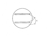
- the light-receiving surface electrode 3 has a large number of finger electrodes 5a, 5b,... 5n arranged in a comb-like shape and intersects with the finger electrodes 5a, 5b,.
- Bus bar electrode 6 is provided, and finger electrodes 5a, 5b,... 5n and bus bar electrode 6 are electrically connected.
- the antireflection film 2 is formed in the remaining region excluding the portion where the light receiving surface electrode 3 is provided. In this way, the electric power generated in the semiconductor substrate 1 is collected by the finger electrodes 5n and taken out to the outside by the bus bar electrodes 6.
- the back electrode 4 is formed on the back surface of the current collecting electrode 7 and the current collecting electrode 7 made of Al or the like formed on the back surface of the p-type semiconductor layer 1b. It is comprised with the extraction electrode 8 which consists of Ag etc. which were electrically connected with the current collection electrode 7. FIG. Then, the electric power generated in the semiconductor substrate 1 is collected by the collecting electrode 7 and is taken out by the extracting electrode 8.
- the conductive paste of the present invention contains conductive powder, glass frit, binder resin, and solvent.
- the solvent contains at least one of a carboxylic acid ester group and a hydroxyl group, and does not include the carboxylic acid ester and the hydroxyl group, and the hydrogen bond term of the Hansen solubility parameter is 7 It is comprised with the mixed solvent containing 1 or more types of 2nd solvent B which is (J / cm ⁇ 3 >) ⁇ 1/2 > or less.
- a polar solvent containing a carboxylic acid ester group or a hydroxyl group, which is a polar group is usually used in consideration of solubility in the binder resin.
- inorganic components such as conductive powder and glass frit wetted with an organic solvent may cause a pattern mask or mesh due to Coulomb force or hydrogen bonding, It adheres to the semiconductor substrate 1 through the antireflection film 2.
- the fluidity of the inorganic component with respect to the pattern and the semiconductor substrate 1 is lowered, plate clogging occurs, the plate slippage is deteriorated, and the printability is lowered.
- the packing property of the inorganic component along the fine concavo-convex structure of the semiconductor substrate 1 is deteriorated, and the desired fire-through property may not be obtained.
- the second solvent B having a nonpolar group is mixed to such an extent that the binder resin does not cause poor dissolution, and the two are mixed. Binder resin is dissolved in the solvent.
- a solvent having a Hansen solubility parameter hydrogen bond term ⁇ h of 7 (J / cm 3 ) 1/2 or less is used as the second solvent B.
- the Hansen solubility parameter is a three-dimensional space obtained by dividing the solubility parameter ⁇ introduced by Hildebrand in regular solution theory into three components: a dispersion term ⁇ d, a polar term ⁇ p, and a hydrogen bond term ⁇ h.
- the solubility parameter ⁇ introduced by Hildebrand is defined as the square root of the cohesive energy density.
- the Hildebrand solubility parameter ⁇ is only applicable to non-polar solvents. For this reason, Hansen extends the concept of the solubility parameter ⁇ , and divides the solubility parameter ⁇ into three components: a dispersion term ⁇ d, a polar term ⁇ p, and a hydrogen bond term ⁇ h, as shown in Equation (1).
- a dispersion term ⁇ d a polar term ⁇ p
- a hydrogen bond term ⁇ h as shown in Equation (1).
- Non-Patent Document 1 “Hansen Solubility Parameters: A User's Handbook", HSPiP 3rd Edition ver.3.0.20
- the hydrogen bond term ⁇ h of the Hansen solubility parameter the value of the above database can be used. However, when there is no description in the database, the Hansen solubility parameter is estimated by the estimation method using the neural network method called Y-MB method. The hydrogen bond term ⁇ h of can be calculated.
- a solvent whose hydrogen bond term ⁇ h is close to the hydrogen bond term ⁇ h of the binder resin easily dissolves the binder resin, and a solvent whose hydrogen bond term ⁇ h is significantly different from the hydrogen bond term ⁇ h of the binder resin dissolves the binder resin. It is difficult to let it.
- the hydrogen bond term ⁇ h is 8 (J / cm 3 ) 1/2 or more, and the carboxylic acid ester group (—COO—) and the hydroxyl group (—OH) have good solubility in the binder resin.
- a solvent containing at least one of them is used as the first solvent A, does not contain both carboxylic acid ester groups and hydroxyl groups, and has a hydrogen bond term ⁇ h of 7 (J / cm 3 ) 1/2 or less with respect to the binder resin.
- What is difficult to dissolve is used as the second solvent B, and a mixed solvent obtained by mixing the first solvent A and the second solvent B is used as the solvent.
- the mixed solvent obtained by mixing the first solvent A and the second solvent B is reduced in polarity to such an extent that the binder resin does not cause poor dissolution. descend.
- the fluidity to the pattern is increased without impairing the solubility of the solvent in the binder resin, the discharge amount to the antireflection film 2 is increased, the plate clogging is less likely to occur, and the plate slippage is improved.
- the fluidity of the inorganic component to the semiconductor substrate 1 is also improved, the packing property of the inorganic component on the surface of the semiconductor substrate is improved. As a result, the fire-through property is improved and the conversion efficiency can be improved.
- the first solvent A is not particularly limited as long as it contains at least one of a carboxylic acid ester group and a hydroxyl group.
- the second solvent B is not particularly limited as long as it does not contain both a carboxylic acid ester group and a hydroxyl group, and the hydrogen bond term ⁇ h of the Hansen solubility parameter is 7 (J / cm 3 ) 1/2 or less.
- these second solvents B it is preferable to use a solvent having a molar ratio of the oxygen component to the carbon component in the molecular structure of 0.3 or more.
- the baking treatment is performed in an extremely short time (for example, 1 to 3 minutes), there is a possibility that a solvent remaining without being dried may be present. Therefore, when a solvent having a molar ratio of carbon component to oxygen component in the molecular structure is less than 0.3, when the solvent burns, the oxygen concentration around the light-receiving surface electrode decreases, and soot generated by combustion causes fire. There is a possibility that the through performance is lowered and the conversion efficiency is lowered.
- the mixing ratio of the first solvent A and the second solvent B is not particularly limited, and is appropriately determined according to the numerical value of the hydrogen bond term ⁇ h of the first solvent A and the second solvent B. can do.
- mixing the ratio A / B of the first solvent A and the second solvent B in the range of 7/1 to 1/3 may hinder the solubility of the binder resin. It is possible to realize a conductive paste that can ensure flowability with respect to a pattern and the semiconductor substrate 1 without being generated, and thereby can obtain a solar cell having good printability and good battery characteristics. it can.
- the binder resin is not particularly limited as long as it can suppress fluidity imparting at the time of paste filling by squeezing at the time of printing or spreading of the paste after release (sagging), etc., ethyl cellulose resin, Cellulose acetate butyrate resin, nitrocellulose resin, urethane resin, fatty acid amide, hydrogenated castor oil, rosin resin, ketone resin, or combinations thereof can be used.
- the glass frit is not particularly limited, and for example, a Si—B—Bi—M glass frit (M is an alkaline earth metal) can be used.
- M is an alkaline earth metal
- Pb-based glass frit has better fire-through properties than non-Pb-based glass frit, but has a large environmental load and is not preferable.
- the present invention is particularly effective when the conductive powder has hydrophilicity. That is, when the conductive powder has hydrophilicity, if only a solvent having a polar group is used, it adheres to the mask or mesh of the pattern and further to the semiconductor substrate 1 due to Coulomb force or hydrogen bonding, and in particular, inorganic to the semiconductor substrate 1 There is a possibility that the packing property of the component is lowered and the fire-through property is lowered.
- the conductive powder has hydrophilicity
- a mixed solvent in which the first solvent A and the second solvent B are mixed is used, the adhesion to the mask is lowered and the fluidity on the semiconductor substrate is reduced.
- the packing property is improved and the fire-through property can be improved.
- the conductive powder is not particularly limited as long as it is a metal powder having good conductivity, but good conductivity without being oxidized even when the baking treatment is performed in the air. Ag powder capable of maintaining the properties can be preferably used.
- the shape of the conductive powder is not particularly limited, and may be, for example, a spherical shape, a flat shape, an irregular shape, or a mixed powder thereof.
- the average particle diameter of the conductive powder is not particularly limited, but from the viewpoint of securing a desired contact point between the conductive powder and the semiconductor substrate 1, in terms of spherical powder, 1. 0 to 5.0 ⁇ m is preferable.
- ZnO facilitates the decomposition and removal of the antireflection film formed in advance on the surface of the semiconductor substrate 1 when firing the conductive paste, thereby enabling smooth fire-through.
- the light-receiving surface electrode 3 and the semiconductor substrate 1 Reduce the contact resistance.
- the decomposition action of the antireflection film occurs at a location where the conductive powder and ZnO are in contact.
- This conductive paste is obtained by weighing, mixing and stirring conductive powder, glass frit, binder resin, and first and second solvents so as to have a predetermined mixing ratio, and using a three-roll mill or the like. It can be easily manufactured by kneading.
- the conductive powder such as Ag, preferably a glass frit substantially free of Pb, a binder resin, and a solvent are contained, and the solvent includes a carboxylic acid ester group and a hydroxyl group.
- the first solvent A containing at least one of them, the carboxylic acid ester and the hydroxyl group are not included, and the hydrogen bond term of the Hansen solubility parameter is 7 (J / cm 3 ) 1/2 or less. Since it contains 1 or more types of 2nd solvent B, the electroconductive paste becomes moderately low in the adhesiveness with respect to the mask or mesh of a pattern at the time of printing.
- the fluidity with respect to the pattern is increased, the discharge amount is increased, the plate clogging is less likely to occur, the plate slippage is improved, and the conductive film is disconnected even after continuous printing. Can be suppressed, and printability is improved.
- liquidity of the inorganic component to a semiconductor substrate also increases, the packing property of the inorganic component with respect to the semiconductor substrate surface improves, As a result, a fire through property improves and it can improve conversion efficiency.
- the second solvent B has at least an oxygen component and a carbon component in the molecular structure, and the molar ratio of the oxygen component to the carbon component is 0.3 or more, so that printability is not impaired. Further, it is possible to further improve the fire-through property.
- the printability and fire-through property can be improved particularly effectively.
- the conductive paste it is possible to achieve both solubility in the binder resin and fluidity in the pattern and the semiconductor substrate.
- the solar cell which concerns on this invention has favorable printability and fire-through property by using the said electrically conductive paste for a light-receiving surface electrode, it is excellent in mass-productivity, and it is in the battery characteristic with favorable conversion efficiency. An excellent solar cell can be obtained.
- the conductive paste may include one or more plasticizers such as di-2-ethylhexyl phthalate and dibutyl phthalate as necessary. It is also preferred to add a combination. Further, a thixotropic agent, a thickener, a dispersant, and the like may be added, and a rheology adjuster such as a fatty acid amide or a fatty acid may be added as necessary.
- the present invention only needs to contain one or more types of the first solvent A and the second solvent, and therefore each of them may contain two or more types.
- ZnO having a specific surface area of 10 m 2 / g, ethyl cellulose resin as a binder resin, B—Si—Bi—Ba-based glass frit, and texanol, dimethyl adipate, BCA, and BC as the first solvent A are prepared. Further, propylene carbonate, DEGDEE, DEGBME, TEGBME and n-tetradecane were prepared as the second solvent B.
- Sample Nos. 1 to 5 are blended with the first solvent A and the second solvent B so that the mixing ratio A / B is 3/1.
- Sample numbers 6 to 10 are comparative example samples using only the first solvent A as the solvent, and sample number 11 is a comparative example sample using only the second solvent B as the solvent.
- an antireflection film having a thickness of 0.1 ⁇ m was formed by plasma enhanced chemical vapor deposition (PECVD) over the entire surface of a single crystal Si-based semiconductor substrate having a length of 50 mm, a width of 50 mm, and a thickness of 0.2 mm.
- PECVD plasma enhanced chemical vapor deposition
- P is diffused into a part of the p-type Si-based semiconductor layer, whereby an n-type Si-based semiconductor layer is formed on the upper surface of the p-type Si-based semiconductor layer.
- an Al paste containing Al and an Ag paste containing Ag were appropriately applied to the back surface of the Si-based semiconductor substrate and dried to produce a back electrode conductive film.
- the continuous printability is determined to be rejected (x) when the conductive film is disconnected at 10 sheets or less during screen printing, and passed ( ⁇ ) when the conductive film is not disconnected even after the continuous 10 sheets. As evaluated. In addition, the presence or absence of the disconnection of a conductive film was judged visually.
- the ejection property is determined by screen printing so that the film thickness of the conductive film is 30 ⁇ m, and screen printing is performed. X), and the case where the film thickness of the conductive film exceeded 21 ⁇ m was evaluated as a pass ( ⁇ ).
- each sample was placed in an oven set at a temperature of 150 ° C. to dry the conductive film.
- FF Pmax / (Voc ⁇ Isc) (2)
- Pmax is the maximum output of the sample
- Voc is the open circuit voltage
- Isc is the short circuit current
- the conversion efficiency ⁇ was obtained from the maximum output Pmax, the area A of the light receiving surface electrode, and the irradiance E based on the formula (3).
- Sample No. 6 uses only texanol containing a carboxylic acid ester group and a hydroxyl group as a solvent. Therefore, disconnection occurred during continuous printing, the film thickness of the conductive film was thin, and dischargeability was lowered. Therefore, it was found that the fill factor FF was as low as 0.745 and the conversion efficiency ⁇ was also as low as 15.78%.
- Sample No. 7 uses only dimethyl adipate containing a carboxylic acid ester group, so that the ejection performance is good, but disconnection occurs during continuous printing, so the fill factor FF is as low as 0.701, The conversion efficiency was also as low as 14.53%.
- Sample Nos. 8 and 9 are mixed with two kinds of solvents, but only the first solvent A containing a carboxylic acid ester group and a hydroxyl group is used. However, disconnection occurred during continuous printing, the fill factor FF was as low as 0.657 and 0.721, and the conversion efficiency ⁇ was as low as 14.00% and 15.50%, respectively.
- Sample No. 10 uses only the first solvent A containing a carboxylic acid ester group and a hydroxyl group, so that the discharge performance is lowered, and thus disconnection occurs during continuous printing, and the film thickness of the conductive film is also thin. . Further, the fill factor FF was as low as 0.715, and the conversion efficiency ⁇ was also low as 15.20%.
- Sample No. 11 uses only propylene carbonate as the second solvent B, the binder resin did not dissolve in the solvent and could not be pasted.
- Sample Nos. 1 to 5 are mixed with the first solvent A and the second solvent B, so that the continuous printability and the discharge property are good, and therefore the fill factor FF is 0.749 to It was found that the conversion efficiency was improved to 0.769 and the conversion efficiency ⁇ was also improved to 16.08 to 16.49%.
- sample numbers 1 to 4 in which the molar ratio of the oxygen component to the carbon component in the molecular structure is 0.3 or more have a fill factor FF and a conversion efficiency ⁇ that are higher than those of sample number 5 in which the molar ratio is less than 0.3. It was found that both improved and the battery characteristics improved.
- Table 3 shows the printability (continuous printability, dischargeability) and battery characteristics (curve factor FF, conversion efficiency ⁇ ) of each sample Nos. 21 to 24.
- a spherical Ag powder having an average particle diameter of 1.6 ⁇ m was prepared as a conductive powder. Then, this Ag powder and stearic acid were mixed, washed and dried, whereby the Ag powder was subjected to a hydrophobic treatment.
- sample numbers 31 to 35 were prepared in the same manner and procedure as in Example 1 with the same solvent type and solvent mixing ratio as those of sample numbers 1 to 3, 5, and 8.
- Table 4 shows the printability (continuous printability, dischargeability) and battery characteristics (curve factor FF, conversion efficiency ⁇ ) of each sample Nos. 31 to 35.
- sample numbers 1 to 3 and 5 and sample number 8 when the Ag powder is hydrophilic, the battery characteristics are remarkably improved.
- the Ag powder is hydrophilic. was found to be more effective.
- a lead-free conductive paste with good printability and discharge properties and good battery characteristics can be realized, whereby a solar cell with high conversion efficiency can be obtained stably and efficiently.
Priority Applications (2)
| Application Number | Priority Date | Filing Date | Title |
|---|---|---|---|
| JP2012557899A JPWO2012111480A1 (ja) | 2011-02-16 | 2012-02-07 | 導電性ペースト及び太陽電池 |
| US13/963,303 US20140007937A1 (en) | 2011-02-16 | 2013-08-09 | Electroconductive paste and solar cell |
Applications Claiming Priority (4)
| Application Number | Priority Date | Filing Date | Title |
|---|---|---|---|
| JP2011030703 | 2011-02-16 | ||
| JP2011-030703 | 2011-02-16 | ||
| JP2011166344 | 2011-07-29 | ||
| JP2011-166344 | 2011-07-29 |
Related Child Applications (1)
| Application Number | Title | Priority Date | Filing Date |
|---|---|---|---|
| US13/963,303 Continuation US20140007937A1 (en) | 2011-02-16 | 2013-08-09 | Electroconductive paste and solar cell |
Publications (1)
| Publication Number | Publication Date |
|---|---|
| WO2012111480A1 true WO2012111480A1 (ja) | 2012-08-23 |
Family
ID=46672408
Family Applications (1)
| Application Number | Title | Priority Date | Filing Date |
|---|---|---|---|
| PCT/JP2012/052708 WO2012111480A1 (ja) | 2011-02-16 | 2012-02-07 | 導電性ペースト及び太陽電池 |
Country Status (4)
| Country | Link |
|---|---|
| US (1) | US20140007937A1 (zh) |
| JP (1) | JPWO2012111480A1 (zh) |
| TW (1) | TW201243866A (zh) |
| WO (1) | WO2012111480A1 (zh) |
Cited By (4)
| Publication number | Priority date | Publication date | Assignee | Title |
|---|---|---|---|---|
| JP2015074768A (ja) * | 2013-10-11 | 2015-04-20 | 住友金属鉱山株式会社 | ペースト組成物 |
| WO2016117392A1 (ja) * | 2015-01-21 | 2016-07-28 | 株式会社ダイセル | 印刷法による電子部品製造用溶剤 |
| JP2018173336A (ja) * | 2017-03-31 | 2018-11-08 | 学校法人 関西大学 | ハンセン溶解度指数の推定方法 |
| CN111868841A (zh) * | 2018-04-19 | 2020-10-30 | 东洋油墨Sc控股株式会社 | 成形膜用导电性组合物、成形膜、成形体及其制造方法 |
Families Citing this family (4)
| Publication number | Priority date | Publication date | Assignee | Title |
|---|---|---|---|---|
| DE102006053689A1 (de) * | 2006-11-13 | 2008-05-15 | Vishay Bccomponents Beyschlag Gmbh | Sensoranordnung |
| EP2463915A4 (en) * | 2009-08-06 | 2014-01-08 | Mitsubishi Electric Corp | METHOD FOR FORMING SOLAR CELL ELECTRODES, METHOD FOR MANUFACTURING SOLAR CELL, AND SOLAR CELL |
| RU2018145297A (ru) | 2013-02-28 | 2019-01-22 | Гардиан Индастриз Корп. | Оконные модули, изготовленные с использованием керамической фритты, которая растворяет покрытия, нанесенные методом физического осаждения из паровой фазы (pvd), и/или соответствующие способы |
| WO2017121740A1 (en) * | 2016-01-15 | 2017-07-20 | Basf Se | Conductive paste |
Citations (7)
| Publication number | Priority date | Publication date | Assignee | Title |
|---|---|---|---|---|
| JP2004273446A (ja) * | 2003-02-18 | 2004-09-30 | Toray Ind Inc | 導電性ペーストおよびそれを用いたディスプレイパネル用部材の製造方法 |
| JP2010097808A (ja) * | 2008-10-16 | 2010-04-30 | Hitachi Chem Co Ltd | 低粘度分散液、これを用いた銅ナノ粒子配線及び複合材料 |
| JP2010199034A (ja) * | 2009-02-27 | 2010-09-09 | Dic Corp | 太陽電池用導電性ペースト及びその製造方法 |
| JP2011142052A (ja) * | 2010-01-08 | 2011-07-21 | Hitachi Chem Co Ltd | 銅導体インク及び導電性基板及びその製造方法 |
| JP2011140598A (ja) * | 2010-01-08 | 2011-07-21 | Hitachi Chem Co Ltd | ナノ粒子分散液の製造方法、及びインクジェット用分散液 |
| JP2011171439A (ja) * | 2010-02-17 | 2011-09-01 | Mitsubishi Materials Corp | 導電性組成物及びそれを用いた太陽電池の製造方法並びに太陽電池 |
| JP2011256382A (ja) * | 2010-06-09 | 2011-12-22 | Xerox Corp | 特定のハンセン溶解度パラメータを有する溶媒を含む銀ナノ粒子組成物 |
Family Cites Families (5)
| Publication number | Priority date | Publication date | Assignee | Title |
|---|---|---|---|---|
| US6083426A (en) * | 1998-06-12 | 2000-07-04 | Matsushita Electric Industrial Co., Ltd. | Conductive paste |
| US7556748B2 (en) * | 2005-04-14 | 2009-07-07 | E. I. Du Pont De Nemours And Company | Method of manufacture of semiconductor device and conductive compositions used therein |
| JP4828269B2 (ja) * | 2006-03-16 | 2011-11-30 | 住友ゴム工業株式会社 | 導電パターンの製造方法 |
| JP2010070669A (ja) * | 2008-09-19 | 2010-04-02 | Fujifilm Corp | インクジェット記録液 |
| PL2416218T3 (pl) * | 2009-03-31 | 2014-07-31 | Toray Industries | Prekursor do bezwodnej litograficznej formy drukowej o bezpośrednim typie drukowania i sposób jego wytwarzania |
-
2012
- 2012-02-07 WO PCT/JP2012/052708 patent/WO2012111480A1/ja active Application Filing
- 2012-02-07 JP JP2012557899A patent/JPWO2012111480A1/ja active Pending
- 2012-02-14 TW TW101104777A patent/TW201243866A/zh unknown
-
2013
- 2013-08-09 US US13/963,303 patent/US20140007937A1/en not_active Abandoned
Patent Citations (7)
| Publication number | Priority date | Publication date | Assignee | Title |
|---|---|---|---|---|
| JP2004273446A (ja) * | 2003-02-18 | 2004-09-30 | Toray Ind Inc | 導電性ペーストおよびそれを用いたディスプレイパネル用部材の製造方法 |
| JP2010097808A (ja) * | 2008-10-16 | 2010-04-30 | Hitachi Chem Co Ltd | 低粘度分散液、これを用いた銅ナノ粒子配線及び複合材料 |
| JP2010199034A (ja) * | 2009-02-27 | 2010-09-09 | Dic Corp | 太陽電池用導電性ペースト及びその製造方法 |
| JP2011142052A (ja) * | 2010-01-08 | 2011-07-21 | Hitachi Chem Co Ltd | 銅導体インク及び導電性基板及びその製造方法 |
| JP2011140598A (ja) * | 2010-01-08 | 2011-07-21 | Hitachi Chem Co Ltd | ナノ粒子分散液の製造方法、及びインクジェット用分散液 |
| JP2011171439A (ja) * | 2010-02-17 | 2011-09-01 | Mitsubishi Materials Corp | 導電性組成物及びそれを用いた太陽電池の製造方法並びに太陽電池 |
| JP2011256382A (ja) * | 2010-06-09 | 2011-12-22 | Xerox Corp | 特定のハンセン溶解度パラメータを有する溶媒を含む銀ナノ粒子組成物 |
Cited By (5)
| Publication number | Priority date | Publication date | Assignee | Title |
|---|---|---|---|---|
| JP2015074768A (ja) * | 2013-10-11 | 2015-04-20 | 住友金属鉱山株式会社 | ペースト組成物 |
| WO2016117392A1 (ja) * | 2015-01-21 | 2016-07-28 | 株式会社ダイセル | 印刷法による電子部品製造用溶剤 |
| JPWO2016117392A1 (ja) * | 2015-01-21 | 2017-10-26 | 株式会社ダイセル | 印刷法による電子部品製造用溶剤 |
| JP2018173336A (ja) * | 2017-03-31 | 2018-11-08 | 学校法人 関西大学 | ハンセン溶解度指数の推定方法 |
| CN111868841A (zh) * | 2018-04-19 | 2020-10-30 | 东洋油墨Sc控股株式会社 | 成形膜用导电性组合物、成形膜、成形体及其制造方法 |
Also Published As
| Publication number | Publication date |
|---|---|
| JPWO2012111480A1 (ja) | 2014-07-03 |
| TW201243866A (en) | 2012-11-01 |
| US20140007937A1 (en) | 2014-01-09 |
Similar Documents
| Publication | Publication Date | Title |
|---|---|---|
| WO2012111480A1 (ja) | 導電性ペースト及び太陽電池 | |
| TWI570748B (zh) | 電極用膠組成物及太陽電池 | |
| JP5816738B1 (ja) | 導電性組成物 | |
| JP6735046B2 (ja) | 太陽電池電極形成用導電性ペースト | |
| TW201533754A (zh) | 電極用膠組成物、太陽電池元件以及太陽電池 | |
| US8748304B2 (en) | Devices containing silver compositions deposited by micro-deposition direct writing silver conductor lines | |
| TW201115592A (en) | Glass compositions used in conductors for photovoltaic cells | |
| TW201515017A (zh) | 一種含無鉛玻璃熔塊之導電漿(一) | |
| KR20140091090A (ko) | 태양전지 전극용 페이스트 조성물 및 이로부터 제조된 전극 | |
| US8128846B2 (en) | Silver composition for micro-deposition direct writing silver conductor lines on photovoltaic wafers | |
| WO2014050704A1 (ja) | 導電性ペースト及び太陽電池 | |
| WO2012111478A1 (ja) | 導電性ペースト及び太陽電池 | |
| JP2017092253A (ja) | 導電性組成物 | |
| JP5403304B2 (ja) | 導電性ペースト、太陽電池、及び太陽電池の製造方法 | |
| JP2019106525A (ja) | 太陽電池 | |
| JP5990315B2 (ja) | 導電性組成物 | |
| JP6074483B1 (ja) | 導電性組成物 | |
| WO2013069727A1 (ja) | 導電性ペースト、及び貫通電極の製造方法 | |
| JP2013504177A (ja) | 光電池のための導体 | |
| JP2011525700A (ja) | 光電池の導体に使用されるサブミクロン粒子を含む組成物の使用方法 | |
| US8008179B2 (en) | Methods using silver compositions for micro-deposition direct writing silver conductor lines on photovoltaic wafers | |
| JP2019106524A (ja) | 太陽電池 | |
| CN110797134B (zh) | 用于太阳能电池电极的组合物以及太阳能电池 | |
| JP2011522423A (ja) | 光電池の導体:サブミクロン粒子を含む組成物 | |
| KR20200078173A (ko) | 태양전지 전극 형성 방법 및 태양전지 |
Legal Events
| Date | Code | Title | Description |
|---|---|---|---|
| 121 | Ep: the epo has been informed by wipo that ep was designated in this application |
Ref document number: 12747426 Country of ref document: EP Kind code of ref document: A1 |
|
| ENP | Entry into the national phase |
Ref document number: 2012557899 Country of ref document: JP Kind code of ref document: A |
|
| NENP | Non-entry into the national phase |
Ref country code: DE |
|
| 122 | Ep: pct application non-entry in european phase |
Ref document number: 12747426 Country of ref document: EP Kind code of ref document: A1 |