WO2012111343A1 - 自動分析機 - Google Patents
自動分析機 Download PDFInfo
- Publication number
- WO2012111343A1 WO2012111343A1 PCT/JP2012/001056 JP2012001056W WO2012111343A1 WO 2012111343 A1 WO2012111343 A1 WO 2012111343A1 JP 2012001056 W JP2012001056 W JP 2012001056W WO 2012111343 A1 WO2012111343 A1 WO 2012111343A1
- Authority
- WO
- WIPO (PCT)
- Prior art keywords
- standard deviation
- liquid
- absorbance
- time
- container
- Prior art date
- Legal status (The legal status is an assumption and is not a legal conclusion. Google has not performed a legal analysis and makes no representation as to the accuracy of the status listed.)
- Ceased
Links
Images


Classifications
-
- G—PHYSICS
- G01—MEASURING; TESTING
- G01N—INVESTIGATING OR ANALYSING MATERIALS BY DETERMINING THEIR CHEMICAL OR PHYSICAL PROPERTIES
- G01N30/00—Investigating or analysing materials by separation into components using adsorption, absorption or similar phenomena or using ion-exchange, e.g. chromatography or field flow fractionation
-
- G—PHYSICS
- G01—MEASURING; TESTING
- G01N—INVESTIGATING OR ANALYSING MATERIALS BY DETERMINING THEIR CHEMICAL OR PHYSICAL PROPERTIES
- G01N21/00—Investigating or analysing materials by the use of optical means, i.e. using sub-millimetre waves, infrared, visible or ultraviolet light
- G01N21/17—Systems in which incident light is modified in accordance with the properties of the material investigated
- G01N21/25—Colour; Spectral properties, i.e. comparison of effect of material on the light at two or more different wavelengths or wavelength bands
- G01N21/31—Investigating relative effect of material at wavelengths characteristic of specific elements or molecules, e.g. atomic absorption spectrometry
-
- G—PHYSICS
- G01—MEASURING; TESTING
- G01N—INVESTIGATING OR ANALYSING MATERIALS BY DETERMINING THEIR CHEMICAL OR PHYSICAL PROPERTIES
- G01N21/00—Investigating or analysing materials by the use of optical means, i.e. using sub-millimetre waves, infrared, visible or ultraviolet light
- G01N21/01—Arrangements or apparatus for facilitating the optical investigation
- G01N21/15—Preventing contamination of the components of the optical system or obstruction of the light path
-
- G—PHYSICS
- G01—MEASURING; TESTING
- G01N—INVESTIGATING OR ANALYSING MATERIALS BY DETERMINING THEIR CHEMICAL OR PHYSICAL PROPERTIES
- G01N21/00—Investigating or analysing materials by the use of optical means, i.e. using sub-millimetre waves, infrared, visible or ultraviolet light
- G01N21/17—Systems in which incident light is modified in accordance with the properties of the material investigated
- G01N21/25—Colour; Spectral properties, i.e. comparison of effect of material on the light at two or more different wavelengths or wavelength bands
- G01N21/251—Colorimeters; Construction thereof
- G01N21/253—Colorimeters; Construction thereof for batch operation, i.e. multisample apparatus
-
- G—PHYSICS
- G01—MEASURING; TESTING
- G01N—INVESTIGATING OR ANALYSING MATERIALS BY DETERMINING THEIR CHEMICAL OR PHYSICAL PROPERTIES
- G01N21/00—Investigating or analysing materials by the use of optical means, i.e. using sub-millimetre waves, infrared, visible or ultraviolet light
- G01N21/84—Systems specially adapted for particular applications
- G01N21/88—Investigating the presence of flaws or contamination
- G01N21/90—Investigating the presence of flaws or contamination in a container or its contents
- G01N21/9018—Dirt detection in containers
-
- G—PHYSICS
- G01—MEASURING; TESTING
- G01N—INVESTIGATING OR ANALYSING MATERIALS BY DETERMINING THEIR CHEMICAL OR PHYSICAL PROPERTIES
- G01N21/00—Investigating or analysing materials by the use of optical means, i.e. using sub-millimetre waves, infrared, visible or ultraviolet light
- G01N21/01—Arrangements or apparatus for facilitating the optical investigation
- G01N21/15—Preventing contamination of the components of the optical system or obstruction of the light path
- G01N2021/155—Monitoring cleanness of window, lens, or other parts
- G01N2021/157—Monitoring by optical means
-
- G—PHYSICS
- G01—MEASURING; TESTING
- G01N—INVESTIGATING OR ANALYSING MATERIALS BY DETERMINING THEIR CHEMICAL OR PHYSICAL PROPERTIES
- G01N35/00—Automatic analysis not limited to methods or materials provided for in any single one of groups G01N1/00 - G01N33/00; Handling materials therefor
- G01N35/00584—Control arrangements for automatic analysers
- G01N35/00722—Communications; Identification
- G01N2035/00891—Displaying information to the operator
- G01N2035/009—Displaying information to the operator alarms, e.g. audible
-
- G—PHYSICS
- G01—MEASURING; TESTING
- G01N—INVESTIGATING OR ANALYSING MATERIALS BY DETERMINING THEIR CHEMICAL OR PHYSICAL PROPERTIES
- G01N2201/00—Features of devices classified in G01N21/00
- G01N2201/04—Batch operation; multisample devices
- G01N2201/0415—Carrusel, sequential
-
- G—PHYSICS
- G01—MEASURING; TESTING
- G01N—INVESTIGATING OR ANALYSING MATERIALS BY DETERMINING THEIR CHEMICAL OR PHYSICAL PROPERTIES
- G01N35/00—Automatic analysis not limited to methods or materials provided for in any single one of groups G01N1/00 - G01N33/00; Handling materials therefor
- G01N35/02—Automatic analysis not limited to methods or materials provided for in any single one of groups G01N1/00 - G01N33/00; Handling materials therefor using a plurality of sample containers moved by a conveyor system past one or more treatment or analysis stations
- G01N35/025—Automatic analysis not limited to methods or materials provided for in any single one of groups G01N1/00 - G01N33/00; Handling materials therefor using a plurality of sample containers moved by a conveyor system past one or more treatment or analysis stations having a carousel or turntable for reaction cells or cuvettes
Definitions
- the present invention relates to a method and an apparatus for detecting that a liquid is overflowing from at least one of a plurality of containers provided in the analyzer, and an analyzer.
- an analyzer for analyzing a sample by dispensing a sample and a reagent into a reaction vessel and measuring the absorbance of a reaction solution generated in the reaction vessel is known.
- This analyzer is equipped with a photometric unit having a light source and a light receiving unit, and after the light source irradiates light to the reaction container containing the reaction liquid, the amount of light transmitted through the reaction liquid in the reaction container received by the light receiving unit The sample is analyzed by calculating the absorbance based on the above.
- the photometry unit continuously irradiates light to a plurality of measurement points on the reaction container, and transmits the light transmitted through the reaction solution.
- the amount of light at the measurement point is low, and the absorbance is calculated as a value higher than the original value.
- Patent Literature 1 discloses an analyzer that excludes the light amount of a protruding measurement point that is different from the light amount of a normal chemical reaction within a plurality of measurement points.
- the method of the present invention is a method for detecting that liquid overflows from at least one of the plurality of containers in an analyzer comprising a plurality of containers containing liquids,
- the method Measuring the absorbance of the liquid contained in the one container at a plurality of locations of one of the plurality of containers at time T1; and Calculating a standard deviation of the absorbance of the liquid measured at a plurality of locations of the one container at time T1, as a first standard deviation; Measuring the absorbance of the liquid contained in the one container at time T2, Calculating a standard deviation of the absorbance of the liquid measured at a plurality of locations of the one container at time T2 as a second standard deviation; Determining whether a difference between the first standard deviation and the second standard deviation is greater than a predetermined threshold; Determining that liquid is overflowing from at least one of the plurality of containers when it is determined that a difference between the first standard deviation and the second standard deviation is greater than the predetermined threshold. It can be determined that the liquid
- the method Measuring the absorbance of the liquid contained in the other one container at a plurality of locations of the other one of the plurality of containers at time T3; Calculating a standard deviation of the absorbance of the liquid measured at a plurality of locations of the other one container at time T3 as a third standard deviation; Measuring the absorbance of the liquid contained in the other one container at time T4; Calculating a standard deviation of the absorbance of the liquid measured at a plurality of locations of the other one container at time T4 as a fourth standard deviation; Determining whether a difference between the third standard deviation and the fourth standard deviation is greater than the predetermined threshold, Determining that at least one of the plurality of containers is overflowing with liquid, It is determined that the difference between the first standard deviation and the second standard deviation is greater than the predetermined threshold, and the difference between the third standard deviation and the fourth standard deviation is greater than the predetermined threshold. May be determined that the liquid is overflowing from at least one of the plurality of containers.
- the method may further include a step of stopping the analyzer when it is determined that liquid is overflowing from at least one of the plurality of containers.
- the method may further include displaying an alarm indicating that the liquid is overflowing when it is determined that the liquid is overflowing from at least one of the plurality of containers.
- the detection apparatus of the present invention is a detection apparatus that detects that liquid overflows from at least one of the plurality of containers in an analyzer including a plurality of containers in which liquids are stored.
- the detection device is: Means for measuring the absorbance of the liquid contained in the one container at a plurality of locations of one of the plurality of containers at time T1; Means for calculating, as a first standard deviation, the standard deviation of the absorbance of the liquid measured at a plurality of locations of the one container at time T1; Means for measuring the absorbance of the liquid contained in the one container at time T2, Means for calculating, as a second standard deviation, the standard deviation of the absorbance of the liquid measured at a plurality of locations of the one container at time T2.
- the detection device is: At time T3, means for measuring the absorbance of the liquid contained in the other one container at a plurality of locations of the other one of the plurality of containers; Means for calculating, as a third standard deviation, the standard deviation of the absorbance of the liquid measured at a plurality of locations of the other one container at time T3; Means for measuring the absorbance of the liquid contained in the other one container at time T4; Means for calculating, as a fourth standard deviation, the standard deviation of the absorbance of the liquid measured at a plurality of locations of the other one container at time T4; Means for determining whether or not a difference between the third standard deviation and the fourth standard deviation is greater than the predetermined threshold; The means for determining that liquid is overflowing from at least one of the plurality of containers, It is determined that the difference between the first standard deviation and the second standard deviation is greater than the predetermined threshold, and the difference between the third standard deviation and the fourth standard deviation is greater than the predetermined threshold. May be determined that the liquid is overflowing from at least
- the analyzer of the present invention is A plurality of containers containing liquid; Means for analyzing a liquid contained in at least one of the plurality of containers; A detection device that detects that liquid overflows from at least one of the plurality of containers, The detection device is: Means for measuring the absorbance of the liquid contained in the one container at a plurality of locations of one of the plurality of containers at time T1; Means for calculating, as a first standard deviation, the standard deviation of the absorbance of the liquid measured at a plurality of locations of the one container at time T1; Means for measuring the absorbance of the liquid contained in the one container at time T2, Means for calculating, as a second standard deviation, the standard deviation of the absorbance of the liquid measured at a plurality of locations of the one container at time T2.
- the detection device is: At time T3, means for measuring the absorbance of the liquid contained in the other one container at a plurality of locations of the other one of the plurality of containers; Means for calculating, as a third standard deviation, the standard deviation of the absorbance of the liquid measured at a plurality of locations of the other one container at time T3; Means for measuring the absorbance of the liquid contained in the other one container at time T4; Means for calculating, as a fourth standard deviation, the standard deviation of the absorbance of the liquid measured at a plurality of locations of the other one container at time T4; Means for determining whether a difference between the third standard deviation and the fourth standard deviation is greater than the predetermined threshold; May further comprise The means for determining that liquid is overflowing from at least one of the plurality of containers, It is determined that the difference between the first standard deviation and the second standard deviation is greater than the predetermined threshold, and the difference between the third standard deviation and the fourth standard deviation is greater than the predetermined threshold. May be determined that the liquid is overflowing from at
- the analyzer can be stopped immediately after detection, and damage caused by liquid overflow can be prevented. Further, according to the present invention, it is possible to notify the user that the liquid is overflowing from the container provided in the analyzer, and it is possible to prevent erroneous reports. Furthermore, even if the function according to the present invention is installed in the analyzer, the cost can be increased.
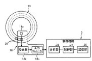
- FIG. 1 shows an example of the configuration of an analyzer 1 according to an embodiment of the present invention.
- FIG. 2 is a schematic diagram showing a schematic configuration of the photometry unit 18 according to the embodiment of the present invention.
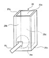
- FIG. 3 is a perspective view of the reaction vessel 20.
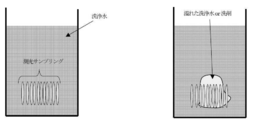
- FIG. 4 shows a normal state when the absorbance of the liquid contained in the reaction container 20 is measured at 11 positions of the reaction container 20 while the reaction container 20 passes through the photometry unit 18 once (left figure: liquid overflow occurs).
- 2 is a schematic diagram of the reaction vessel 20 when there is an abnormality (when there is a liquid overflow).
- FIG. 5 shows an example of a processing procedure for detecting that the liquid overflows from at least one of the plurality of reaction containers provided in the analyzer 1.
- FIG. 6 shows another example of the processing procedure for detecting that the liquid overflows from at least one of the plurality of reaction vessels provided in the analyzer 1.
- FIG. 1 shows an example of the configuration of an analyzer 1 according to an embodiment of the present invention.
- the analyzer 1 controls a measurement mechanism 2 that measures the absorbance of a liquid contained in a reaction vessel 20, and controls the entire analyzer 1 including the measurement mechanism 2, and measures in the measurement mechanism 2.
- a control mechanism 3 for analyzing the results.
- the analysis device 1 automatically detects that the liquid overflows from the reaction container provided in the analysis device 1 and analyzes the sample by cooperation of these two mechanisms.
- the measurement mechanism 2 includes a sample transport unit 11 that sequentially transports a sample rack 11b that holds a plurality of sample containers 11a containing samples such as blood and urine in the direction of the arrow in the figure, and a sample transport.
- a specimen dispensing mechanism 12 that dispenses a specimen contained in a specimen container 11a that is stationary at a predetermined position of the unit 11 into a reaction container 20, and a plurality of reaction containers 20 are held along the circumferential direction
- the reaction table 13 that moves the reaction container 20 to a predetermined position by orbiting in the direction of the arrow, the reagent container 14 that stores a plurality of reagent containers 15 that store the reagents dispensed in the reaction container 20, and the reagent
- a reagent dispensing mechanism 16 that dispenses a reagent contained in a reagent container 15 that is stationary at a predetermined position in the chamber 14 into the reaction container 20, and agitation that stirs the specimen and the reagent dispensed into the reaction container 20.
- Part 17 and accommodated in reaction vessel 20 It includes a metering unit 18 for measuring the absorbance of the liquid, and a cleaning unit 19 for cleaning the reaction vessel 20 being.
- the control mechanism 3 includes a control unit 31, an input unit 32, an analysis unit 33, a liquid overflow detection unit 34, a storage unit 35, an output unit 36, and a transmission / reception unit 37.
- the input unit 32, the analysis unit 33, the liquid overflow detection unit 34, the storage unit 35, the output unit 36, and the transmission / reception unit 37 are electrically connected to the control unit 31.
- the control unit 31 is realized by a CPU or the like, and controls processing and operation of each unit of the analyzer 1.
- the control unit 31 performs a predetermined process on information input from each component of the analyzer 1 and outputs information obtained by performing the predetermined process to each component.
- the input unit 32 is realized by a keyboard, a mouse, a touch panel having an input / output function, and the like, and obtains various information necessary for analyzing a sample, instruction information for analysis operation, and the like from the outside.
- the analysis unit 33 performs component analysis of the specimen based on the measurement result of the absorbance measured by the photometry unit 18.
- the liquid overflow detection unit 34 overflows liquid from at least one of the reaction containers 20 based on the absorbance of the liquid stored in the reaction container 20 measured by the photometry unit 18 during the cleaning process of the reaction container 20. Is detected.
- the liquid overflow detection unit 34 includes a standard deviation calculation unit 34a, a standard deviation determination unit 34b, and a liquid overflow determination unit 34c.
- the liquid overflow detection unit 34 may further include a notification processing unit 34d.
- the standard deviation calculation unit 34a is configured to measure the standard deviation of the absorbance of the plurality of liquids measured by the photometry unit 18 at a plurality of locations of the reaction vessel 20 while the reaction vessel 20 passes the photometry unit 18 once. It is calculated every time it passes through the section 18.
- the standard deviation determination unit 34b is configured to measure the absorbance of the plurality of liquids measured by the photometry unit 18 for each specific reaction vessel in the reaction vessel 20 while the reaction vessel passes through the photometry unit 18 once at a certain time.
- the liquid overflow determining unit 34c overflows liquid from at least one of the reaction containers 20 when the standard deviation determining unit 34b determines that the difference in standard deviation is greater than a predetermined threshold.
- the notification processing unit 34d issues an alarm indicating that the liquid is overflowing via the control unit 31. Output to the output unit 36.
- the storage unit 35 is realized by using a hard disk that stores information magnetically and a memory that loads various programs related to this process from the hard disk and electrically stores them when the analysis apparatus 1 executes the process. Various information including the analysis result of the specimen is stored.
- the storage unit 35 may include an auxiliary storage device that can read information stored in a storage medium such as a CD-ROM, a DVD-ROM, or a PC card.
- the output unit 36 is realized by a display, a printer, a speaker, and the like, and outputs various information.
- the transmission / reception unit 37 has a function as an interface for transmitting / receiving information according to a predetermined format via a communication network (not shown).
- the photometry unit 18 is configured to store the liquid contained in the reaction container 20 during the cleaning process by the cleaning unit 19 of the plurality of reaction containers 20 that are sequentially transferred on the reaction table 13. By measuring the absorbance and analyzing the liquid overflow detection unit 34 based on the measurement result, it is detected whether or not the liquid is overflowing from at least one of the reaction containers 20.
- the analysis apparatus 1 configured as described above performs sample component analysis or the like, the reagent dispensing mechanism 16 is provided with a reagent storage for a plurality of reaction containers 20 that are sequentially transferred on the reaction table 13.
- the sample dispensing mechanism 12 After dispensing the reagent from the 14 reagent containers 15, the sample dispensing mechanism 12 dispenses the sample from the sample container 11a at the sample aspirating position. Thereafter, the photometry unit 18 measures the absorbance of the reaction solution in a state in which the reagent and the sample are reacted, and the analysis unit 33 analyzes based on the measurement result to automatically perform the component analysis of the sample. Is called. Thereafter, the cleaning unit 19 cleans the reaction container 20 transported after the measurement by the photometry unit 18 is completed.
- FIG. 2 is a schematic diagram showing a schematic configuration of the photometry unit 18.
- FIG. 3 is a perspective view of the reaction vessel 20.
- the photometry unit 18 includes a light source 18a, a light receiving unit 18b, and an A / D converter 18c.
- the light source 18a and the light receiving unit 18b are arranged at positions facing each other across the reaction container 20 held by the reaction table 13.
- the light source 18 a is disposed on the inner peripheral side of the reaction table 13.
- the light receiving unit 18 b is disposed on the outer peripheral side of the reaction table 13.
- the light source 18a is realized by a halogen lamp or the like, and irradiates the reaction vessel 20 with light for analysis.
- the light receiving unit 18b measures a diffraction grating such as a concave diffraction grating and the light dispersed by the diffraction grating for each spectrum determined by the measurement item, and outputs a signal corresponding to the light quantity, a CCD sensor, a CMOS sensor And other light receiving sensors.
- the A / D converter 18 c converts the signal output from the light receiving unit 18 b into a digital value and outputs the digital value to the control unit 31.
- the reaction vessel 20 is a very small vessel having a capacity of, for example, several nL to several mL, and a liquid holding portion 20d that holds liquid is formed by the side wall 20a, the side wall 20b, and the bottom wall 20c.
- An opening 20e is provided above the liquid holding part 20d.
- the reaction container 20 includes a transparent material that transmits 80% or more of light included in the analysis light BL (for example, analysis light having a wavelength of 340 to 800 nm) irradiated from the light source 18a of the photometry unit 18, for example, heat-resistant glass. Synthetic resins such as glass, cyclic olefin and polystyrene are used.
- the reaction vessel 20 is arranged with the side wall 20b facing the radial direction of the reaction table 13.
- the reaction vessel 20 has a side wall as a photometric region Am through which the analysis light BL passes when passing through the analysis light BL irradiated by the light source of the photometry unit 18 as the reaction table 13 rotates.
- the lower part of 20b is used.
- the shape of the reaction vessel 20 is not limited to the shape of a rectangular parallelepiped as shown in FIG. 3 as long as the measurement of absorbance at a plurality of locations in the reaction vessel 20 does not vary. It is only necessary that the two surfaces of the side walls of which are exposed to the analysis light are parallel.
- FIG. 4 shows a normal state when the absorbance of the liquid contained in the reaction container 20 is measured at 11 locations of the reaction container 20 while the reaction container 20 passes through the photometry unit 18 once (left figure: liquid overflow).
- 2 is a schematic diagram of the reaction vessel 20 when there is no liquid) and when there is an abnormality (right figure: when there is liquid overflow).
- Each of the elongated regions of the photometric sampling in FIG. 4 corresponds to a location where the liquid absorbance is measured. Under normal conditions, since washing water or detergent does not adhere to the photometric surface, the variation in photometric sampling data is small, and the standard deviation of absorbance is small.
- this standard deviation of absorbance is a unique value for each reaction vessel and for each wavelength. Therefore, the reproducibility of the standard deviation of the absorbance is high when the absorbance of the liquid in the same reaction vessel is measured at the same wavelength under normal conditions. Thus, under normal conditions, the reproducibility of the standard deviation of the absorbance when measuring the absorbance of the liquid in the same reaction container at the same wavelength is high, so each of the liquid in the same reaction container measured at the same wavelength at two times The difference in the standard deviation of absorbance at the time of is small.
- the absorbance of the liquid in the same reaction vessel is measured at the same wavelength when abnormal, as opposed to normal.
- the reproducibility of the absorbance is low.
- the reproducibility of the standard deviation of the absorbance when the absorbance of the liquid in the same reaction vessel is measured at the same wavelength is low, so each of the liquid in the same reaction vessel measured at the same wavelength at two times The difference in the standard deviation of absorbance at the time of is large.
- the difference in the standard deviation of the absorbance at each time of the liquid in the same reaction vessel measured at the same wavelength at two times at normal time is small, and at the same wavelength at two times at abnormal time. Liquid overflow is detected by utilizing this feature that the difference in standard deviation of absorbance at each time of the liquid in the same reaction vessel is large.
- the difference between the standard deviation of the absorbance at each time of the liquid in the same reaction container measured at the same wavelength at two times and the magnitude of the predetermined threshold are compared, and the liquid is Detects overflow. If the standard deviation difference is less than the predetermined threshold value, it corresponds to the normal state, so it is determined that there is no liquid overflow. If the standard deviation difference is greater than or equal to the predetermined threshold value, it corresponds to the abnormal time, so the liquid overflows. It is judged that there is.
- FIG. 5 shows an example of a processing procedure for detecting that the liquid overflows from at least one of the plurality of reaction vessels provided in the analyzer 1. This processing procedure is performed during the cleaning process of the reaction vessel 20. In this processing procedure, the absorbance is measured at the same wavelength.
- Step S501 At time T1 when the specific reaction container of the plurality of reaction containers 20 is transferred by the reaction table 13 and passes through the photometry unit 18, it is accommodated in the specific reaction container by the photometry unit 18. The absorbance of the liquid is measured at a predetermined number of locations.
- Step S502 The standard deviation calculation unit 34a calculates the standard deviation of the absorbance of the liquid measured at a predetermined number of locations in the specific one reaction vessel at time T1 from the absorbance measured in step S501. The calculated standard deviation is stored in the storage unit 35.
- Step S503 At time T2 when the specific reaction container is transferred by the reaction table 13 and again passes through the photometry unit 18, the photometry unit 18 determines the absorbance of the liquid contained in the specific reaction container. Measure at a predetermined number of locations.
- Step S504 The standard deviation calculator 34a calculates the standard deviation of the absorbance of the liquid measured at a predetermined number of locations in the specific one reaction vessel at time T2 from the absorbance measured in step S503. The calculated standard deviation is stored in the storage unit 35.
- Step S505 It is determined whether or not the difference between the standard deviation calculated in step S502 and stored in the storage unit 35 and the standard deviation calculated in step S504 and stored in the storage unit 35 is greater than a predetermined threshold value. .
- the predetermined threshold is stored in advance in the storage unit 35.
- Step S506 When it is determined in step S505 that the difference in standard deviation is larger than the predetermined threshold, it is determined that at least one of the reaction containers 20 is overflowing with liquid.
- the analyzer 1 may be stopped, and an alarm indicating that the liquid is overflowing may be displayed by the notification processing unit 34d via the output unit 36. .
- step S505 when it is determined in step S505 that the difference in standard deviation is equal to or less than a predetermined threshold, the time when the specific reaction container passes through the photometry unit 18 again by the reaction table 13 At T3, the photometry unit 18 measures the absorbance of the liquid contained in the one specific reaction container at a predetermined number of locations, and the standard deviation calculation unit 34a determines the specific at the time T3 from the measured absorbance.
- the standard deviation of the absorbance of the liquid measured at a predetermined number of locations in one reaction vessel was calculated, the calculated standard deviation was stored in the storage unit 35, calculated for time T2, and stored in the storage unit 35.
- step S505 it is determined whether or not the difference between the standard deviation and the standard deviation calculated for time T3 and stored in the storage unit 35 is larger than a predetermined threshold value. 3 ⁇ S505 repeatedly, the process proceeds to step S506 if it is judged to be larger than the predetermined threshold value, may be repeated S503 ⁇ S505 again when it is determined to be equal to or lower than a predetermined threshold value.
- the specific reaction container may be any of the plurality of reaction containers 20.
- the time T1 and the time T2 are the times at which the absorbance of the liquid contained in the specific reaction container can be measured, that is, any time as long as the specific reaction container passes through the photometry unit 18. However, the difference between the time T1 and the time T2 is also arbitrary.
- the time T2 may be a time when the specific reaction container passes through the photometry unit 18 next to the time T1.
- the cleaning process is the detergent cleaning process 1, the detergent cleaning process 2, the cleaning water cleaning process 1, the cleaning water cleaning process 2, the cleaning water cleaning process 3, the cleaning water cleaning process 4, the suction process 1, the drying process 1, and the drying process 2.
- the photometric step of either step S501 or step S503 may be performed every time after the washing water cleaning step 4, and the photometric step of step S501 or step S503 is performed for each cleaning step (detergent). It may be performed every time after the washing steps 1 and 2 and the washing water washing steps 1 to 4).
- the state after the washing water washing process 4 is a state in which the reaction container is sufficiently washed, so that there is a possibility of erroneous detection due to dirt or remaining test solution. Therefore, performing the photometric step after each cleaning step has an advantage that the detection sensitivity is increased because more parts are determined.
- the absorbance is measured at the same wavelength, but may be measured at a plurality of wavelengths.
- the two values of the standard deviation and the predetermined threshold used in step S505 need to be for the same wavelength.
- FIG. 6 shows another example of the processing procedure for detecting that the liquid overflows from at least one of the plurality of reaction containers provided in the analyzer 1. This processing procedure is performed during the cleaning process of the reaction vessel 20. In this processing procedure, the absorbance is measured at the same wavelength.
- Step S601 At time T1 when the specific reaction container of the plurality of reaction containers 20 is transferred by the reaction table 13 and passes through the photometry unit 18, it is accommodated in the specific reaction container by the photometry unit 18. The absorbance of the liquid is measured at a predetermined number of locations.
- Step S602 The standard deviation calculation unit 34a calculates the standard deviation of the absorbance of the liquid measured at a predetermined number of locations in the specific one reaction container at time T1 from the absorbance measured in step S601. The calculated standard deviation is stored in the storage unit 35.
- Step S603 At time T2 when the specific reaction container is transferred by the reaction table 13 and again passes the photometry unit 18, the photometry unit 18 determines the absorbance of the liquid contained in the specific reaction container. Measure at a predetermined number of locations.
- Step S604 The standard deviation calculator 34a calculates the standard deviation of the absorbance of the liquid measured at a predetermined number of locations in the specific one reaction vessel at time T2 from the absorbance measured in step S603. The calculated standard deviation is stored in the storage unit 35.
- Step S605 It is determined whether or not the difference between the standard deviation calculated in step S602 and stored in the storage unit 35 and the standard deviation calculated in step S604 and stored in the storage unit 35 is greater than a predetermined threshold value. .
- the predetermined threshold is stored in advance in the storage unit 35.
- Step S606 At time T3 when another specific reaction container of the plurality of reaction containers 20 is transferred by the reaction table 13 and passes through the photometry unit 18, the specific another reaction is performed by the photometry unit 18 The absorbance of the liquid stored in the container is measured at a predetermined number of locations.
- Step S607 The standard deviation calculation unit 34a calculates the standard deviation of the absorbance of the liquid measured at a predetermined number of locations in the specific another reaction container at time T3 from the absorbance measured in step S606. The calculated standard deviation is stored in the storage unit 35.
- Step S608 At time T4 when the specific another reaction container is transferred by the reaction table 13 and passes through the photometry unit 18 again, it is accommodated in the specific another reaction container by the photometry unit 18.
- the liquid absorbance is measured at a predetermined number of locations.
- Step S609 The standard deviation calculation unit 34a calculates the standard deviation of the absorbance of the liquid measured at a predetermined number of locations in the specific another reaction container at time T4 from the absorbance measured in step S608. The calculated standard deviation is stored in the storage unit 35.
- Step S610 It is determined whether or not the difference between the standard deviation calculated in step S607 and stored in the storage unit 35 and the standard deviation calculated in step S609 and stored in the storage unit 35 is greater than a predetermined threshold value. .
- the predetermined threshold is the same as the predetermined threshold used in step S605.
- Step S611 If it is determined in step S605 that the standard deviation difference is greater than the predetermined threshold value, and if it is determined in step S610 that the standard deviation difference is greater than the predetermined threshold value, at least one of the reaction vessels 20 Judge that liquid is overflowing from one reaction vessel.
- the analyzer 1 may be stopped, and an alarm indicating that the liquid is overflowing may be displayed by the notification processing unit 34d via the output unit 36. .
- step S605 or step S610 When it is determined in step S605 or step S610 that one of the standard deviation differences is equal to or smaller than the predetermined threshold, time T5 is transferred by the reaction table 13 and the specific one reaction container passes through the photometry unit 18 again.
- the photometry unit 18 measures the absorbance of the liquid contained in the one specific reaction container at a predetermined number of locations, and the standard deviation calculation unit 34a determines the specific absorbance at time T5 from the measured absorbance.
- the standard deviation of the absorbance of the liquid measured at a predetermined number of locations in one reaction vessel is calculated, the calculated standard deviation is stored in the storage unit 35, the standard calculated for time T2 and stored in the storage unit 35 It is determined whether or not the difference between the deviation and the standard deviation calculated for the time T5 and stored in the storage unit 35 is larger than a predetermined threshold, and the reaction table 3 at time T6 when the other specific reaction container passes through the photometry unit 18 again by the photometry unit 18, the absorbance of the liquid stored in the specific another reaction container is determined by the photometry unit 18
- the standard deviation calculation unit 34a calculates the standard deviation of the absorbance of the liquid measured at a predetermined number of points in the specific another reaction container at time T6 from the measured absorbance in the standard deviation calculator 34a.
- the calculated standard deviation is stored in the storage unit 35, and the difference between the standard deviation calculated for the time T4 and stored in the storage unit 35 and the standard deviation calculated for the time T6 and stored in the storage unit 35 is Steps S603 to S605 and S608 to S610 are repeated so as to determine whether or not the threshold value is larger than the predetermined threshold value, and the difference in standard deviation and the previous value for the specific one reaction vessel are repeated. If it is determined that both the standard deviation differences for another specific reaction container are both greater than the predetermined threshold value, the process proceeds to step S611, and if any of them is determined to be equal to or less than the predetermined threshold value, S603 to S605 and S608 to S610 may be repeated.
- the specific one reaction container and the specific another reaction container may be any of the plurality of reaction containers 20.
- the relationship between the one specific reaction vessel and the one other specific reaction vessel is also arbitrary.
- the relationship between the one specific reaction vessel and the one other specific reaction vessel may be a relationship that is separated by one-fifth turn, or may be separated by one-half turn. It may be a relationship.
- the time T1 and the time T2 are the times at which the absorbance of the liquid contained in the specific reaction container can be measured, that is, any time as long as the specific reaction container passes through the photometry unit 18. However, the difference between the time T1 and the time T2 is also arbitrary.
- the time T2 may be a time when the specific reaction container passes through the photometry unit 18 next to the time T1.
- time T3 and the time T4 are times when the absorbance of the liquid contained in the specific another reaction container can be measured, that is, the specific another reaction container passes through the photometry unit 18. Any time may be used as long as it is within the range, and the difference between time T3 and time T4 is also arbitrary.
- the time T4 may be a time when the another specific reaction container passes through the photometry unit 18 after the time T3.
- the cleaning process is the detergent cleaning process 1, the detergent cleaning process 2, the cleaning water cleaning process 1, the cleaning water cleaning process 2, the cleaning water cleaning process 3, the cleaning water cleaning process 4, the suction process 1, the drying process 1, and the drying process 2.
- the photometric step of step S601, step S603, step S606, or step S608 may be performed every time after the washing water washing step 4, and step S601, step S603, step S606, or Any of the photometric steps in step S608 may be performed after every cleaning process (detergent cleaning process 1-2, cleaning water cleaning process 1-4).
- the state after the washing water washing process 4 is a state in which the reaction container is sufficiently washed, and there is a possibility that it is erroneously detected due to dirt or remaining test solution.
- the detection sensitivity is increased because more parts are determined.
- the absorbance is measured at the same wavelength, but it may be measured at a plurality of wavelengths.
- the three values of the two standard deviations and the predetermined threshold used in steps S605 and S610 need to be for the same wavelength.
- the difference in standard deviation is greater than or equal to a predetermined threshold due to reasons other than the overflow of liquid (for example, the reason that bubbles in the reaction vessel have moved between time T1 and time T2).
- a predetermined threshold due to reasons other than the overflow of liquid (for example, the reason that bubbles in the reaction vessel have moved between time T1 and time T2).
- the liquid from at least one of the reaction containers 20 is determined based on the determination of whether the difference between the standard deviations for the two reaction containers is greater than a predetermined threshold.
- the number of reaction containers used for determining that the liquid is overflowing from the reaction container is not limited to one or two of the embodiments shown in FIGS. . Three or more may be sufficient.
- the analyzer 1 having a configuration in which the reaction vessel 20 is arranged in a circle and is transferred in the circumferential direction by the reaction table 13 is described, this configuration is for the purpose of explanation, and the present invention is The configuration is not limited to this.
- the measurement target reaction container or the photometric unit 18 may be configured to be movable so that the measurement target reaction container can be measured by the photometric unit 18. It is obvious that even in such a configuration, it is possible to detect that the liquid according to the present invention is overflowing.
- the analyzer 1 having a configuration in which the photometry unit 18 and the liquid overflow detection unit 34 are separated from each other has been described, this configuration is for the purpose of explanation, and the present invention is not limited to this configuration.
- the photometry unit 18 and the liquid overflow detection unit 34 may be configured as one device called a detection device. It is obvious that even in such a configuration, it is possible to detect that the liquid according to the present invention is overflowing.
- the predetermined threshold used in the embodiment shown in FIGS. 5 and 6 is a predetermined threshold and is stored in the storage unit 35.
- the predetermined threshold for the embodiment shown in FIG. An example of the determination method will be described.
- the predetermined threshold is obtained from a sufficient number of standard deviation data (standard deviation difference data calculated in step S604 and step S609 in the embodiment shown in FIG. 6) and from the probability of occurrence of erroneous detection. .
- the probability that the difference in standard deviation exceeds the threshold value twice in succession is 9.52 ⁇ 10 ⁇ 8 .
- the probability that the difference in standard deviation exceeds the threshold once is obtained by using the binomial distribution.
- p corresponds to the probability that the difference in standard deviation exceeds the threshold once when normal
- P (x) is about 9.52 ⁇ 10 ⁇ 8 because it corresponds to the probability that the standard deviation difference exceeds the threshold twice in succession
- n is 2 because it corresponds to the number of determinations
- x is 2 because it corresponds to the number of times the threshold is exceeded.
- the threshold value is a position that is the probability of p obtained above in the difference data of the standard deviation. That is, when there are 1 million pieces of data, the predetermined threshold is determined to be the 309th difference value from the largest difference.
Landscapes
- Physics & Mathematics (AREA)
- Health & Medical Sciences (AREA)
- Life Sciences & Earth Sciences (AREA)
- Chemical & Material Sciences (AREA)
- Analytical Chemistry (AREA)
- Biochemistry (AREA)
- General Health & Medical Sciences (AREA)
- General Physics & Mathematics (AREA)
- Immunology (AREA)
- Pathology (AREA)
- Spectroscopy & Molecular Physics (AREA)
- Automatic Analysis And Handling Materials Therefor (AREA)
Priority Applications (3)
| Application Number | Priority Date | Filing Date | Title |
|---|---|---|---|
| US13/986,000 US10078070B2 (en) | 2011-02-17 | 2012-02-17 | Automated analyzer |
| CN201280009304.3A CN103380381B (zh) | 2011-02-17 | 2012-02-17 | 检测液体从多个容器中的至少一个容器溢出的方法和系统 |
| EP12747497.1A EP2677322B1 (en) | 2011-02-17 | 2012-02-17 | Automated analyzer |
Applications Claiming Priority (2)
| Application Number | Priority Date | Filing Date | Title |
|---|---|---|---|
| JP2011032332A JP5711564B2 (ja) | 2011-02-17 | 2011-02-17 | 自動分析機 |
| JP2011-032332 | 2011-02-17 |
Publications (1)
| Publication Number | Publication Date |
|---|---|
| WO2012111343A1 true WO2012111343A1 (ja) | 2012-08-23 |
Family
ID=46672287
Family Applications (1)
| Application Number | Title | Priority Date | Filing Date |
|---|---|---|---|
| PCT/JP2012/001056 Ceased WO2012111343A1 (ja) | 2011-02-17 | 2012-02-17 | 自動分析機 |
Country Status (5)
| Country | Link |
|---|---|
| US (1) | US10078070B2 (enExample) |
| EP (1) | EP2677322B1 (enExample) |
| JP (1) | JP5711564B2 (enExample) |
| CN (1) | CN103380381B (enExample) |
| WO (1) | WO2012111343A1 (enExample) |
Families Citing this family (4)
| Publication number | Priority date | Publication date | Assignee | Title |
|---|---|---|---|---|
| JP5865470B1 (ja) * | 2014-11-28 | 2016-02-17 | 上野精機株式会社 | 電子部品搬送装置 |
| JP7109967B2 (ja) * | 2018-04-04 | 2022-08-01 | キヤノンメディカルシステムズ株式会社 | 自動分析装置 |
| TWI670473B (zh) * | 2018-09-12 | 2019-09-01 | 財團法人工業技術研究院 | 液位檢測方法及其裝置 |
| CN111829951A (zh) * | 2020-08-12 | 2020-10-27 | 安徽清大云博环保科技有限公司 | 一种具有报警机构的微量硅酸根分析仪及其工作方法 |
Citations (5)
| Publication number | Priority date | Publication date | Assignee | Title |
|---|---|---|---|---|
| JP2001091518A (ja) * | 1999-09-20 | 2001-04-06 | Hitachi Ltd | 自動分析装置 |
| JP2007198739A (ja) | 2006-01-23 | 2007-08-09 | Hitachi High-Technologies Corp | 自動分析装置 |
| JP2008209353A (ja) * | 2007-02-28 | 2008-09-11 | Denso Corp | 液体性状検出方法 |
| JP2010151519A (ja) | 2008-12-24 | 2010-07-08 | Hitachi High-Technologies Corp | 自動分析装置 |
| JP2010160116A (ja) | 2009-01-09 | 2010-07-22 | Beckman Coulter Inc | 自動分析装置 |
Family Cites Families (20)
| Publication number | Priority date | Publication date | Assignee | Title |
|---|---|---|---|---|
| EP0041366B1 (en) * | 1980-05-30 | 1986-09-10 | Hitachi, Ltd. | Method for operating an apparatus for analysing samples optically |
| JPH0736021B2 (ja) * | 1984-07-14 | 1995-04-19 | 株式会社島津製作所 | 自動化学分析装置 |
| US4958295A (en) * | 1986-05-21 | 1990-09-18 | Hercules Incorporated | Analyzing apparatus and method for analysis of liquid samples |
| US4858768A (en) * | 1986-08-04 | 1989-08-22 | The Coca-Cola Company | Method for discrimination between contaminated and uncontaminated containers |
| US5230863A (en) * | 1987-07-21 | 1993-07-27 | Si Industrial Instruments, Inc. | Method of calibrating an automatic chemical analyzer |
| US6098029A (en) * | 1994-06-14 | 2000-08-01 | Hitachi, Ltd. | Liquid-level position measuring method and system |
| JP3794012B2 (ja) * | 1999-03-10 | 2006-07-05 | 日本電子株式会社 | 回転反応器の測定方式 |
| ITTO20010189A1 (it) | 2001-03-02 | 2002-09-02 | Gambro Dasco Spa | Metodo per misurare la concentrazione di emoglobina nel sangue in un circuito di una macchina di dialisi, dispositivo di misura e circuito p |
| US20050185176A1 (en) * | 2004-02-23 | 2005-08-25 | Moran Donald J.Jr. | Determining an analyte by multiple measurements through a cuvette |
| DE102005048053A1 (de) * | 2005-10-07 | 2007-04-12 | Voith Patent Gmbh | Messvorrichtung, insbesondere zur Messung von Entwässerungsmengen von Papiermaschinen |
| US7634378B2 (en) * | 2007-11-30 | 2009-12-15 | Siemens Healthcare Diagnostics Inc. | Detection of insufficient sample during aspiration with a pipette |
| JP5255265B2 (ja) * | 2007-12-18 | 2013-08-07 | ベックマン コールター, インコーポレイテッド | 洗浄装置および自動分析装置 |
| JP4991586B2 (ja) * | 2008-01-31 | 2012-08-01 | 株式会社日立ハイテクノロジーズ | 自動分析装置 |
| JP2009229140A (ja) * | 2008-03-19 | 2009-10-08 | Olympus Corp | 自動分析装置 |
| CN102216784B (zh) * | 2008-11-17 | 2014-07-09 | 株式会社日立高新技术 | 自动分析装置 |
| JP2010243307A (ja) * | 2009-04-06 | 2010-10-28 | Toshiba Corp | 自動分析装置 |
| JP5520519B2 (ja) * | 2009-05-20 | 2014-06-11 | 株式会社日立ハイテクノロジーズ | 自動分析装置及び分析方法 |
| US8715574B2 (en) * | 2009-06-19 | 2014-05-06 | Abbott Laboratories | System for managing inventory of bulk liquids |
| EP2316795A1 (en) * | 2009-11-03 | 2011-05-04 | Koninklijke Philips Electronics N.V. | Device for subjecting a liquid to a purifying process |
| US8790592B2 (en) * | 2010-02-04 | 2014-07-29 | Bio-Rad Laboratories, Inc. | Measuring multi-analyte samples using an in-line flow cell |
-
2011
- 2011-02-17 JP JP2011032332A patent/JP5711564B2/ja active Active
-
2012
- 2012-02-17 WO PCT/JP2012/001056 patent/WO2012111343A1/ja not_active Ceased
- 2012-02-17 EP EP12747497.1A patent/EP2677322B1/en not_active Not-in-force
- 2012-02-17 CN CN201280009304.3A patent/CN103380381B/zh active Active
- 2012-02-17 US US13/986,000 patent/US10078070B2/en active Active
Patent Citations (5)
| Publication number | Priority date | Publication date | Assignee | Title |
|---|---|---|---|---|
| JP2001091518A (ja) * | 1999-09-20 | 2001-04-06 | Hitachi Ltd | 自動分析装置 |
| JP2007198739A (ja) | 2006-01-23 | 2007-08-09 | Hitachi High-Technologies Corp | 自動分析装置 |
| JP2008209353A (ja) * | 2007-02-28 | 2008-09-11 | Denso Corp | 液体性状検出方法 |
| JP2010151519A (ja) | 2008-12-24 | 2010-07-08 | Hitachi High-Technologies Corp | 自動分析装置 |
| JP2010160116A (ja) | 2009-01-09 | 2010-07-22 | Beckman Coulter Inc | 自動分析装置 |
Non-Patent Citations (1)
| Title |
|---|
| See also references of EP2677322A4 |
Also Published As
| Publication number | Publication date |
|---|---|
| JP2012173002A (ja) | 2012-09-10 |
| US20140005952A1 (en) | 2014-01-02 |
| EP2677322A1 (en) | 2013-12-25 |
| CN103380381A (zh) | 2013-10-30 |
| CN103380381B (zh) | 2015-01-07 |
| EP2677322B1 (en) | 2020-10-21 |
| JP5711564B2 (ja) | 2015-05-07 |
| US10078070B2 (en) | 2018-09-18 |
| EP2677322A4 (en) | 2017-12-13 |
Similar Documents
| Publication | Publication Date | Title |
|---|---|---|
| JP5350811B2 (ja) | 自動分析装置 | |
| US9506942B2 (en) | Automatic analyzer and method for detecting measurement value abnormalities | |
| EP2667182B1 (en) | Automatic analysis device taking into account thermal drift | |
| US9513305B2 (en) | Multiple cleaning stations for a dispensing probe | |
| WO2015093166A1 (ja) | 自動分析装置 | |
| JP2010151519A (ja) | 自動分析装置 | |
| EP2009448B1 (en) | Automatic analyzing apparatus and quality control method for analysis supporting liquid in the same | |
| JP5711564B2 (ja) | 自動分析機 | |
| JP7330785B2 (ja) | 自動分析装置 | |
| EP3640648B1 (en) | Test method, dispensing device | |
| JP5993737B2 (ja) | 自動分析装置 | |
| JP6242252B2 (ja) | 自動分析装置及び異常検出方法 | |
| JP2009047638A (ja) | 自動分析装置 | |
| JP7246498B2 (ja) | 複合型自動分析装置、システム、及び異常判定方法 | |
| JP5839849B2 (ja) | 自動分析装置 | |
| JP2008076342A (ja) | 自動分析装置 | |
| JP6313960B2 (ja) | 自動分析装置 | |
| EP3667328A1 (en) | Automatic analysis device | |
| WO2024237046A1 (ja) | 自動分析装置およびタイミング設定方法 | |
| JP7109965B2 (ja) | 自動分析装置 | |
| JP2007285920A (ja) | 分析装置 | |
| JP6462224B2 (ja) | 自動分析装置 |
Legal Events
| Date | Code | Title | Description |
|---|---|---|---|
| 121 | Ep: the epo has been informed by wipo that ep was designated in this application |
Ref document number: 12747497 Country of ref document: EP Kind code of ref document: A1 |
|
| NENP | Non-entry into the national phase |
Ref country code: DE |
|
| WWE | Wipo information: entry into national phase |
Ref document number: 2012747497 Country of ref document: EP |
|
| WWE | Wipo information: entry into national phase |
Ref document number: 13986000 Country of ref document: US |