WO2012111343A1 - Automated analyzer - Google Patents
Automated analyzer Download PDFInfo
- Publication number
- WO2012111343A1 WO2012111343A1 PCT/JP2012/001056 JP2012001056W WO2012111343A1 WO 2012111343 A1 WO2012111343 A1 WO 2012111343A1 JP 2012001056 W JP2012001056 W JP 2012001056W WO 2012111343 A1 WO2012111343 A1 WO 2012111343A1
- Authority
- WO
- WIPO (PCT)
- Prior art keywords
- standard deviation
- liquid
- absorbance
- time
- container
- Prior art date
Links
Images


Classifications
-
- G—PHYSICS
- G01—MEASURING; TESTING
- G01N—INVESTIGATING OR ANALYSING MATERIALS BY DETERMINING THEIR CHEMICAL OR PHYSICAL PROPERTIES
- G01N30/00—Investigating or analysing materials by separation into components using adsorption, absorption or similar phenomena or using ion-exchange, e.g. chromatography or field flow fractionation
-
- G—PHYSICS
- G01—MEASURING; TESTING
- G01N—INVESTIGATING OR ANALYSING MATERIALS BY DETERMINING THEIR CHEMICAL OR PHYSICAL PROPERTIES
- G01N21/00—Investigating or analysing materials by the use of optical means, i.e. using sub-millimetre waves, infrared, visible or ultraviolet light
- G01N21/17—Systems in which incident light is modified in accordance with the properties of the material investigated
- G01N21/25—Colour; Spectral properties, i.e. comparison of effect of material on the light at two or more different wavelengths or wavelength bands
- G01N21/31—Investigating relative effect of material at wavelengths characteristic of specific elements or molecules, e.g. atomic absorption spectrometry
-
- G—PHYSICS
- G01—MEASURING; TESTING
- G01N—INVESTIGATING OR ANALYSING MATERIALS BY DETERMINING THEIR CHEMICAL OR PHYSICAL PROPERTIES
- G01N21/00—Investigating or analysing materials by the use of optical means, i.e. using sub-millimetre waves, infrared, visible or ultraviolet light
- G01N21/01—Arrangements or apparatus for facilitating the optical investigation
- G01N21/15—Preventing contamination of the components of the optical system or obstruction of the light path
-
- G—PHYSICS
- G01—MEASURING; TESTING
- G01N—INVESTIGATING OR ANALYSING MATERIALS BY DETERMINING THEIR CHEMICAL OR PHYSICAL PROPERTIES
- G01N21/00—Investigating or analysing materials by the use of optical means, i.e. using sub-millimetre waves, infrared, visible or ultraviolet light
- G01N21/17—Systems in which incident light is modified in accordance with the properties of the material investigated
- G01N21/25—Colour; Spectral properties, i.e. comparison of effect of material on the light at two or more different wavelengths or wavelength bands
- G01N21/251—Colorimeters; Construction thereof
- G01N21/253—Colorimeters; Construction thereof for batch operation, i.e. multisample apparatus
-
- G—PHYSICS
- G01—MEASURING; TESTING
- G01N—INVESTIGATING OR ANALYSING MATERIALS BY DETERMINING THEIR CHEMICAL OR PHYSICAL PROPERTIES
- G01N21/00—Investigating or analysing materials by the use of optical means, i.e. using sub-millimetre waves, infrared, visible or ultraviolet light
- G01N21/84—Systems specially adapted for particular applications
- G01N21/88—Investigating the presence of flaws or contamination
- G01N21/90—Investigating the presence of flaws or contamination in a container or its contents
- G01N21/9018—Dirt detection in containers
-
- G—PHYSICS
- G01—MEASURING; TESTING
- G01N—INVESTIGATING OR ANALYSING MATERIALS BY DETERMINING THEIR CHEMICAL OR PHYSICAL PROPERTIES
- G01N21/00—Investigating or analysing materials by the use of optical means, i.e. using sub-millimetre waves, infrared, visible or ultraviolet light
- G01N21/01—Arrangements or apparatus for facilitating the optical investigation
- G01N21/15—Preventing contamination of the components of the optical system or obstruction of the light path
- G01N2021/155—Monitoring cleanness of window, lens, or other parts
- G01N2021/157—Monitoring by optical means
-
- G—PHYSICS
- G01—MEASURING; TESTING
- G01N—INVESTIGATING OR ANALYSING MATERIALS BY DETERMINING THEIR CHEMICAL OR PHYSICAL PROPERTIES
- G01N35/00—Automatic analysis not limited to methods or materials provided for in any single one of groups G01N1/00 - G01N33/00; Handling materials therefor
- G01N35/00584—Control arrangements for automatic analysers
- G01N35/00722—Communications; Identification
- G01N2035/00891—Displaying information to the operator
- G01N2035/009—Displaying information to the operator alarms, e.g. audible
-
- G—PHYSICS
- G01—MEASURING; TESTING
- G01N—INVESTIGATING OR ANALYSING MATERIALS BY DETERMINING THEIR CHEMICAL OR PHYSICAL PROPERTIES
- G01N2201/00—Features of devices classified in G01N21/00
- G01N2201/04—Batch operation; multisample devices
- G01N2201/0415—Carrusel, sequential
-
- G—PHYSICS
- G01—MEASURING; TESTING
- G01N—INVESTIGATING OR ANALYSING MATERIALS BY DETERMINING THEIR CHEMICAL OR PHYSICAL PROPERTIES
- G01N35/00—Automatic analysis not limited to methods or materials provided for in any single one of groups G01N1/00 - G01N33/00; Handling materials therefor
- G01N35/02—Automatic analysis not limited to methods or materials provided for in any single one of groups G01N1/00 - G01N33/00; Handling materials therefor using a plurality of sample containers moved by a conveyor system past one or more treatment or analysis stations
- G01N35/025—Automatic analysis not limited to methods or materials provided for in any single one of groups G01N1/00 - G01N33/00; Handling materials therefor using a plurality of sample containers moved by a conveyor system past one or more treatment or analysis stations having a carousel or turntable for reaction cells or cuvettes
Definitions
- the present invention relates to a method and an apparatus for detecting that a liquid is overflowing from at least one of a plurality of containers provided in the analyzer, and an analyzer.
- an analyzer for analyzing a sample by dispensing a sample and a reagent into a reaction vessel and measuring the absorbance of a reaction solution generated in the reaction vessel is known.
- This analyzer is equipped with a photometric unit having a light source and a light receiving unit, and after the light source irradiates light to the reaction container containing the reaction liquid, the amount of light transmitted through the reaction liquid in the reaction container received by the light receiving unit The sample is analyzed by calculating the absorbance based on the above.
- the photometry unit continuously irradiates light to a plurality of measurement points on the reaction container, and transmits the light transmitted through the reaction solution.
- the amount of light at the measurement point is low, and the absorbance is calculated as a value higher than the original value.
- Patent Literature 1 discloses an analyzer that excludes the light amount of a protruding measurement point that is different from the light amount of a normal chemical reaction within a plurality of measurement points.
- the method of the present invention is a method for detecting that liquid overflows from at least one of the plurality of containers in an analyzer comprising a plurality of containers containing liquids,
- the method Measuring the absorbance of the liquid contained in the one container at a plurality of locations of one of the plurality of containers at time T1; and Calculating a standard deviation of the absorbance of the liquid measured at a plurality of locations of the one container at time T1, as a first standard deviation; Measuring the absorbance of the liquid contained in the one container at time T2, Calculating a standard deviation of the absorbance of the liquid measured at a plurality of locations of the one container at time T2 as a second standard deviation; Determining whether a difference between the first standard deviation and the second standard deviation is greater than a predetermined threshold; Determining that liquid is overflowing from at least one of the plurality of containers when it is determined that a difference between the first standard deviation and the second standard deviation is greater than the predetermined threshold. It can be determined that the liquid
- the method Measuring the absorbance of the liquid contained in the other one container at a plurality of locations of the other one of the plurality of containers at time T3; Calculating a standard deviation of the absorbance of the liquid measured at a plurality of locations of the other one container at time T3 as a third standard deviation; Measuring the absorbance of the liquid contained in the other one container at time T4; Calculating a standard deviation of the absorbance of the liquid measured at a plurality of locations of the other one container at time T4 as a fourth standard deviation; Determining whether a difference between the third standard deviation and the fourth standard deviation is greater than the predetermined threshold, Determining that at least one of the plurality of containers is overflowing with liquid, It is determined that the difference between the first standard deviation and the second standard deviation is greater than the predetermined threshold, and the difference between the third standard deviation and the fourth standard deviation is greater than the predetermined threshold. May be determined that the liquid is overflowing from at least one of the plurality of containers.
- the method may further include a step of stopping the analyzer when it is determined that liquid is overflowing from at least one of the plurality of containers.
- the method may further include displaying an alarm indicating that the liquid is overflowing when it is determined that the liquid is overflowing from at least one of the plurality of containers.
- the detection apparatus of the present invention is a detection apparatus that detects that liquid overflows from at least one of the plurality of containers in an analyzer including a plurality of containers in which liquids are stored.
- the detection device is: Means for measuring the absorbance of the liquid contained in the one container at a plurality of locations of one of the plurality of containers at time T1; Means for calculating, as a first standard deviation, the standard deviation of the absorbance of the liquid measured at a plurality of locations of the one container at time T1; Means for measuring the absorbance of the liquid contained in the one container at time T2, Means for calculating, as a second standard deviation, the standard deviation of the absorbance of the liquid measured at a plurality of locations of the one container at time T2.
- the detection device is: At time T3, means for measuring the absorbance of the liquid contained in the other one container at a plurality of locations of the other one of the plurality of containers; Means for calculating, as a third standard deviation, the standard deviation of the absorbance of the liquid measured at a plurality of locations of the other one container at time T3; Means for measuring the absorbance of the liquid contained in the other one container at time T4; Means for calculating, as a fourth standard deviation, the standard deviation of the absorbance of the liquid measured at a plurality of locations of the other one container at time T4; Means for determining whether or not a difference between the third standard deviation and the fourth standard deviation is greater than the predetermined threshold; The means for determining that liquid is overflowing from at least one of the plurality of containers, It is determined that the difference between the first standard deviation and the second standard deviation is greater than the predetermined threshold, and the difference between the third standard deviation and the fourth standard deviation is greater than the predetermined threshold. May be determined that the liquid is overflowing from at least
- the analyzer of the present invention is A plurality of containers containing liquid; Means for analyzing a liquid contained in at least one of the plurality of containers; A detection device that detects that liquid overflows from at least one of the plurality of containers, The detection device is: Means for measuring the absorbance of the liquid contained in the one container at a plurality of locations of one of the plurality of containers at time T1; Means for calculating, as a first standard deviation, the standard deviation of the absorbance of the liquid measured at a plurality of locations of the one container at time T1; Means for measuring the absorbance of the liquid contained in the one container at time T2, Means for calculating, as a second standard deviation, the standard deviation of the absorbance of the liquid measured at a plurality of locations of the one container at time T2.
- the detection device is: At time T3, means for measuring the absorbance of the liquid contained in the other one container at a plurality of locations of the other one of the plurality of containers; Means for calculating, as a third standard deviation, the standard deviation of the absorbance of the liquid measured at a plurality of locations of the other one container at time T3; Means for measuring the absorbance of the liquid contained in the other one container at time T4; Means for calculating, as a fourth standard deviation, the standard deviation of the absorbance of the liquid measured at a plurality of locations of the other one container at time T4; Means for determining whether a difference between the third standard deviation and the fourth standard deviation is greater than the predetermined threshold; May further comprise The means for determining that liquid is overflowing from at least one of the plurality of containers, It is determined that the difference between the first standard deviation and the second standard deviation is greater than the predetermined threshold, and the difference between the third standard deviation and the fourth standard deviation is greater than the predetermined threshold. May be determined that the liquid is overflowing from at
- the analyzer can be stopped immediately after detection, and damage caused by liquid overflow can be prevented. Further, according to the present invention, it is possible to notify the user that the liquid is overflowing from the container provided in the analyzer, and it is possible to prevent erroneous reports. Furthermore, even if the function according to the present invention is installed in the analyzer, the cost can be increased.
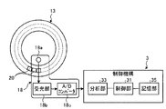
- FIG. 1 shows an example of the configuration of an analyzer 1 according to an embodiment of the present invention.
- FIG. 2 is a schematic diagram showing a schematic configuration of the photometry unit 18 according to the embodiment of the present invention.
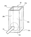
- FIG. 3 is a perspective view of the reaction vessel 20.
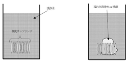
- FIG. 4 shows a normal state when the absorbance of the liquid contained in the reaction container 20 is measured at 11 positions of the reaction container 20 while the reaction container 20 passes through the photometry unit 18 once (left figure: liquid overflow occurs).
- 2 is a schematic diagram of the reaction vessel 20 when there is an abnormality (when there is a liquid overflow).
- FIG. 5 shows an example of a processing procedure for detecting that the liquid overflows from at least one of the plurality of reaction containers provided in the analyzer 1.
- FIG. 6 shows another example of the processing procedure for detecting that the liquid overflows from at least one of the plurality of reaction vessels provided in the analyzer 1.
- FIG. 1 shows an example of the configuration of an analyzer 1 according to an embodiment of the present invention.
- the analyzer 1 controls a measurement mechanism 2 that measures the absorbance of a liquid contained in a reaction vessel 20, and controls the entire analyzer 1 including the measurement mechanism 2, and measures in the measurement mechanism 2.
- a control mechanism 3 for analyzing the results.
- the analysis device 1 automatically detects that the liquid overflows from the reaction container provided in the analysis device 1 and analyzes the sample by cooperation of these two mechanisms.
- the measurement mechanism 2 includes a sample transport unit 11 that sequentially transports a sample rack 11b that holds a plurality of sample containers 11a containing samples such as blood and urine in the direction of the arrow in the figure, and a sample transport.
- a specimen dispensing mechanism 12 that dispenses a specimen contained in a specimen container 11a that is stationary at a predetermined position of the unit 11 into a reaction container 20, and a plurality of reaction containers 20 are held along the circumferential direction
- the reaction table 13 that moves the reaction container 20 to a predetermined position by orbiting in the direction of the arrow, the reagent container 14 that stores a plurality of reagent containers 15 that store the reagents dispensed in the reaction container 20, and the reagent
- a reagent dispensing mechanism 16 that dispenses a reagent contained in a reagent container 15 that is stationary at a predetermined position in the chamber 14 into the reaction container 20, and agitation that stirs the specimen and the reagent dispensed into the reaction container 20.
- Part 17 and accommodated in reaction vessel 20 It includes a metering unit 18 for measuring the absorbance of the liquid, and a cleaning unit 19 for cleaning the reaction vessel 20 being.
- the control mechanism 3 includes a control unit 31, an input unit 32, an analysis unit 33, a liquid overflow detection unit 34, a storage unit 35, an output unit 36, and a transmission / reception unit 37.
- the input unit 32, the analysis unit 33, the liquid overflow detection unit 34, the storage unit 35, the output unit 36, and the transmission / reception unit 37 are electrically connected to the control unit 31.
- the control unit 31 is realized by a CPU or the like, and controls processing and operation of each unit of the analyzer 1.
- the control unit 31 performs a predetermined process on information input from each component of the analyzer 1 and outputs information obtained by performing the predetermined process to each component.
- the input unit 32 is realized by a keyboard, a mouse, a touch panel having an input / output function, and the like, and obtains various information necessary for analyzing a sample, instruction information for analysis operation, and the like from the outside.
- the analysis unit 33 performs component analysis of the specimen based on the measurement result of the absorbance measured by the photometry unit 18.
- the liquid overflow detection unit 34 overflows liquid from at least one of the reaction containers 20 based on the absorbance of the liquid stored in the reaction container 20 measured by the photometry unit 18 during the cleaning process of the reaction container 20. Is detected.
- the liquid overflow detection unit 34 includes a standard deviation calculation unit 34a, a standard deviation determination unit 34b, and a liquid overflow determination unit 34c.
- the liquid overflow detection unit 34 may further include a notification processing unit 34d.
- the standard deviation calculation unit 34a is configured to measure the standard deviation of the absorbance of the plurality of liquids measured by the photometry unit 18 at a plurality of locations of the reaction vessel 20 while the reaction vessel 20 passes the photometry unit 18 once. It is calculated every time it passes through the section 18.
- the standard deviation determination unit 34b is configured to measure the absorbance of the plurality of liquids measured by the photometry unit 18 for each specific reaction vessel in the reaction vessel 20 while the reaction vessel passes through the photometry unit 18 once at a certain time.
- the liquid overflow determining unit 34c overflows liquid from at least one of the reaction containers 20 when the standard deviation determining unit 34b determines that the difference in standard deviation is greater than a predetermined threshold.
- the notification processing unit 34d issues an alarm indicating that the liquid is overflowing via the control unit 31. Output to the output unit 36.
- the storage unit 35 is realized by using a hard disk that stores information magnetically and a memory that loads various programs related to this process from the hard disk and electrically stores them when the analysis apparatus 1 executes the process. Various information including the analysis result of the specimen is stored.
- the storage unit 35 may include an auxiliary storage device that can read information stored in a storage medium such as a CD-ROM, a DVD-ROM, or a PC card.
- the output unit 36 is realized by a display, a printer, a speaker, and the like, and outputs various information.
- the transmission / reception unit 37 has a function as an interface for transmitting / receiving information according to a predetermined format via a communication network (not shown).
- the photometry unit 18 is configured to store the liquid contained in the reaction container 20 during the cleaning process by the cleaning unit 19 of the plurality of reaction containers 20 that are sequentially transferred on the reaction table 13. By measuring the absorbance and analyzing the liquid overflow detection unit 34 based on the measurement result, it is detected whether or not the liquid is overflowing from at least one of the reaction containers 20.
- the analysis apparatus 1 configured as described above performs sample component analysis or the like, the reagent dispensing mechanism 16 is provided with a reagent storage for a plurality of reaction containers 20 that are sequentially transferred on the reaction table 13.
- the sample dispensing mechanism 12 After dispensing the reagent from the 14 reagent containers 15, the sample dispensing mechanism 12 dispenses the sample from the sample container 11a at the sample aspirating position. Thereafter, the photometry unit 18 measures the absorbance of the reaction solution in a state in which the reagent and the sample are reacted, and the analysis unit 33 analyzes based on the measurement result to automatically perform the component analysis of the sample. Is called. Thereafter, the cleaning unit 19 cleans the reaction container 20 transported after the measurement by the photometry unit 18 is completed.
- FIG. 2 is a schematic diagram showing a schematic configuration of the photometry unit 18.
- FIG. 3 is a perspective view of the reaction vessel 20.
- the photometry unit 18 includes a light source 18a, a light receiving unit 18b, and an A / D converter 18c.
- the light source 18a and the light receiving unit 18b are arranged at positions facing each other across the reaction container 20 held by the reaction table 13.
- the light source 18 a is disposed on the inner peripheral side of the reaction table 13.
- the light receiving unit 18 b is disposed on the outer peripheral side of the reaction table 13.
- the light source 18a is realized by a halogen lamp or the like, and irradiates the reaction vessel 20 with light for analysis.
- the light receiving unit 18b measures a diffraction grating such as a concave diffraction grating and the light dispersed by the diffraction grating for each spectrum determined by the measurement item, and outputs a signal corresponding to the light quantity, a CCD sensor, a CMOS sensor And other light receiving sensors.
- the A / D converter 18 c converts the signal output from the light receiving unit 18 b into a digital value and outputs the digital value to the control unit 31.
- the reaction vessel 20 is a very small vessel having a capacity of, for example, several nL to several mL, and a liquid holding portion 20d that holds liquid is formed by the side wall 20a, the side wall 20b, and the bottom wall 20c.
- An opening 20e is provided above the liquid holding part 20d.
- the reaction container 20 includes a transparent material that transmits 80% or more of light included in the analysis light BL (for example, analysis light having a wavelength of 340 to 800 nm) irradiated from the light source 18a of the photometry unit 18, for example, heat-resistant glass. Synthetic resins such as glass, cyclic olefin and polystyrene are used.
- the reaction vessel 20 is arranged with the side wall 20b facing the radial direction of the reaction table 13.
- the reaction vessel 20 has a side wall as a photometric region Am through which the analysis light BL passes when passing through the analysis light BL irradiated by the light source of the photometry unit 18 as the reaction table 13 rotates.
- the lower part of 20b is used.
- the shape of the reaction vessel 20 is not limited to the shape of a rectangular parallelepiped as shown in FIG. 3 as long as the measurement of absorbance at a plurality of locations in the reaction vessel 20 does not vary. It is only necessary that the two surfaces of the side walls of which are exposed to the analysis light are parallel.
- FIG. 4 shows a normal state when the absorbance of the liquid contained in the reaction container 20 is measured at 11 locations of the reaction container 20 while the reaction container 20 passes through the photometry unit 18 once (left figure: liquid overflow).
- 2 is a schematic diagram of the reaction vessel 20 when there is no liquid) and when there is an abnormality (right figure: when there is liquid overflow).
- Each of the elongated regions of the photometric sampling in FIG. 4 corresponds to a location where the liquid absorbance is measured. Under normal conditions, since washing water or detergent does not adhere to the photometric surface, the variation in photometric sampling data is small, and the standard deviation of absorbance is small.
- this standard deviation of absorbance is a unique value for each reaction vessel and for each wavelength. Therefore, the reproducibility of the standard deviation of the absorbance is high when the absorbance of the liquid in the same reaction vessel is measured at the same wavelength under normal conditions. Thus, under normal conditions, the reproducibility of the standard deviation of the absorbance when measuring the absorbance of the liquid in the same reaction container at the same wavelength is high, so each of the liquid in the same reaction container measured at the same wavelength at two times The difference in the standard deviation of absorbance at the time of is small.
- the absorbance of the liquid in the same reaction vessel is measured at the same wavelength when abnormal, as opposed to normal.
- the reproducibility of the absorbance is low.
- the reproducibility of the standard deviation of the absorbance when the absorbance of the liquid in the same reaction vessel is measured at the same wavelength is low, so each of the liquid in the same reaction vessel measured at the same wavelength at two times The difference in the standard deviation of absorbance at the time of is large.
- the difference in the standard deviation of the absorbance at each time of the liquid in the same reaction vessel measured at the same wavelength at two times at normal time is small, and at the same wavelength at two times at abnormal time. Liquid overflow is detected by utilizing this feature that the difference in standard deviation of absorbance at each time of the liquid in the same reaction vessel is large.
- the difference between the standard deviation of the absorbance at each time of the liquid in the same reaction container measured at the same wavelength at two times and the magnitude of the predetermined threshold are compared, and the liquid is Detects overflow. If the standard deviation difference is less than the predetermined threshold value, it corresponds to the normal state, so it is determined that there is no liquid overflow. If the standard deviation difference is greater than or equal to the predetermined threshold value, it corresponds to the abnormal time, so the liquid overflows. It is judged that there is.
- FIG. 5 shows an example of a processing procedure for detecting that the liquid overflows from at least one of the plurality of reaction vessels provided in the analyzer 1. This processing procedure is performed during the cleaning process of the reaction vessel 20. In this processing procedure, the absorbance is measured at the same wavelength.
- Step S501 At time T1 when the specific reaction container of the plurality of reaction containers 20 is transferred by the reaction table 13 and passes through the photometry unit 18, it is accommodated in the specific reaction container by the photometry unit 18. The absorbance of the liquid is measured at a predetermined number of locations.
- Step S502 The standard deviation calculation unit 34a calculates the standard deviation of the absorbance of the liquid measured at a predetermined number of locations in the specific one reaction vessel at time T1 from the absorbance measured in step S501. The calculated standard deviation is stored in the storage unit 35.
- Step S503 At time T2 when the specific reaction container is transferred by the reaction table 13 and again passes through the photometry unit 18, the photometry unit 18 determines the absorbance of the liquid contained in the specific reaction container. Measure at a predetermined number of locations.
- Step S504 The standard deviation calculator 34a calculates the standard deviation of the absorbance of the liquid measured at a predetermined number of locations in the specific one reaction vessel at time T2 from the absorbance measured in step S503. The calculated standard deviation is stored in the storage unit 35.
- Step S505 It is determined whether or not the difference between the standard deviation calculated in step S502 and stored in the storage unit 35 and the standard deviation calculated in step S504 and stored in the storage unit 35 is greater than a predetermined threshold value. .
- the predetermined threshold is stored in advance in the storage unit 35.
- Step S506 When it is determined in step S505 that the difference in standard deviation is larger than the predetermined threshold, it is determined that at least one of the reaction containers 20 is overflowing with liquid.
- the analyzer 1 may be stopped, and an alarm indicating that the liquid is overflowing may be displayed by the notification processing unit 34d via the output unit 36. .
- step S505 when it is determined in step S505 that the difference in standard deviation is equal to or less than a predetermined threshold, the time when the specific reaction container passes through the photometry unit 18 again by the reaction table 13 At T3, the photometry unit 18 measures the absorbance of the liquid contained in the one specific reaction container at a predetermined number of locations, and the standard deviation calculation unit 34a determines the specific at the time T3 from the measured absorbance.
- the standard deviation of the absorbance of the liquid measured at a predetermined number of locations in one reaction vessel was calculated, the calculated standard deviation was stored in the storage unit 35, calculated for time T2, and stored in the storage unit 35.
- step S505 it is determined whether or not the difference between the standard deviation and the standard deviation calculated for time T3 and stored in the storage unit 35 is larger than a predetermined threshold value. 3 ⁇ S505 repeatedly, the process proceeds to step S506 if it is judged to be larger than the predetermined threshold value, may be repeated S503 ⁇ S505 again when it is determined to be equal to or lower than a predetermined threshold value.
- the specific reaction container may be any of the plurality of reaction containers 20.
- the time T1 and the time T2 are the times at which the absorbance of the liquid contained in the specific reaction container can be measured, that is, any time as long as the specific reaction container passes through the photometry unit 18. However, the difference between the time T1 and the time T2 is also arbitrary.
- the time T2 may be a time when the specific reaction container passes through the photometry unit 18 next to the time T1.
- the cleaning process is the detergent cleaning process 1, the detergent cleaning process 2, the cleaning water cleaning process 1, the cleaning water cleaning process 2, the cleaning water cleaning process 3, the cleaning water cleaning process 4, the suction process 1, the drying process 1, and the drying process 2.
- the photometric step of either step S501 or step S503 may be performed every time after the washing water cleaning step 4, and the photometric step of step S501 or step S503 is performed for each cleaning step (detergent). It may be performed every time after the washing steps 1 and 2 and the washing water washing steps 1 to 4).
- the state after the washing water washing process 4 is a state in which the reaction container is sufficiently washed, so that there is a possibility of erroneous detection due to dirt or remaining test solution. Therefore, performing the photometric step after each cleaning step has an advantage that the detection sensitivity is increased because more parts are determined.
- the absorbance is measured at the same wavelength, but may be measured at a plurality of wavelengths.
- the two values of the standard deviation and the predetermined threshold used in step S505 need to be for the same wavelength.
- FIG. 6 shows another example of the processing procedure for detecting that the liquid overflows from at least one of the plurality of reaction containers provided in the analyzer 1. This processing procedure is performed during the cleaning process of the reaction vessel 20. In this processing procedure, the absorbance is measured at the same wavelength.
- Step S601 At time T1 when the specific reaction container of the plurality of reaction containers 20 is transferred by the reaction table 13 and passes through the photometry unit 18, it is accommodated in the specific reaction container by the photometry unit 18. The absorbance of the liquid is measured at a predetermined number of locations.
- Step S602 The standard deviation calculation unit 34a calculates the standard deviation of the absorbance of the liquid measured at a predetermined number of locations in the specific one reaction container at time T1 from the absorbance measured in step S601. The calculated standard deviation is stored in the storage unit 35.
- Step S603 At time T2 when the specific reaction container is transferred by the reaction table 13 and again passes the photometry unit 18, the photometry unit 18 determines the absorbance of the liquid contained in the specific reaction container. Measure at a predetermined number of locations.
- Step S604 The standard deviation calculator 34a calculates the standard deviation of the absorbance of the liquid measured at a predetermined number of locations in the specific one reaction vessel at time T2 from the absorbance measured in step S603. The calculated standard deviation is stored in the storage unit 35.
- Step S605 It is determined whether or not the difference between the standard deviation calculated in step S602 and stored in the storage unit 35 and the standard deviation calculated in step S604 and stored in the storage unit 35 is greater than a predetermined threshold value. .
- the predetermined threshold is stored in advance in the storage unit 35.
- Step S606 At time T3 when another specific reaction container of the plurality of reaction containers 20 is transferred by the reaction table 13 and passes through the photometry unit 18, the specific another reaction is performed by the photometry unit 18 The absorbance of the liquid stored in the container is measured at a predetermined number of locations.
- Step S607 The standard deviation calculation unit 34a calculates the standard deviation of the absorbance of the liquid measured at a predetermined number of locations in the specific another reaction container at time T3 from the absorbance measured in step S606. The calculated standard deviation is stored in the storage unit 35.
- Step S608 At time T4 when the specific another reaction container is transferred by the reaction table 13 and passes through the photometry unit 18 again, it is accommodated in the specific another reaction container by the photometry unit 18.
- the liquid absorbance is measured at a predetermined number of locations.
- Step S609 The standard deviation calculation unit 34a calculates the standard deviation of the absorbance of the liquid measured at a predetermined number of locations in the specific another reaction container at time T4 from the absorbance measured in step S608. The calculated standard deviation is stored in the storage unit 35.
- Step S610 It is determined whether or not the difference between the standard deviation calculated in step S607 and stored in the storage unit 35 and the standard deviation calculated in step S609 and stored in the storage unit 35 is greater than a predetermined threshold value. .
- the predetermined threshold is the same as the predetermined threshold used in step S605.
- Step S611 If it is determined in step S605 that the standard deviation difference is greater than the predetermined threshold value, and if it is determined in step S610 that the standard deviation difference is greater than the predetermined threshold value, at least one of the reaction vessels 20 Judge that liquid is overflowing from one reaction vessel.
- the analyzer 1 may be stopped, and an alarm indicating that the liquid is overflowing may be displayed by the notification processing unit 34d via the output unit 36. .
- step S605 or step S610 When it is determined in step S605 or step S610 that one of the standard deviation differences is equal to or smaller than the predetermined threshold, time T5 is transferred by the reaction table 13 and the specific one reaction container passes through the photometry unit 18 again.
- the photometry unit 18 measures the absorbance of the liquid contained in the one specific reaction container at a predetermined number of locations, and the standard deviation calculation unit 34a determines the specific absorbance at time T5 from the measured absorbance.
- the standard deviation of the absorbance of the liquid measured at a predetermined number of locations in one reaction vessel is calculated, the calculated standard deviation is stored in the storage unit 35, the standard calculated for time T2 and stored in the storage unit 35 It is determined whether or not the difference between the deviation and the standard deviation calculated for the time T5 and stored in the storage unit 35 is larger than a predetermined threshold, and the reaction table 3 at time T6 when the other specific reaction container passes through the photometry unit 18 again by the photometry unit 18, the absorbance of the liquid stored in the specific another reaction container is determined by the photometry unit 18
- the standard deviation calculation unit 34a calculates the standard deviation of the absorbance of the liquid measured at a predetermined number of points in the specific another reaction container at time T6 from the measured absorbance in the standard deviation calculator 34a.
- the calculated standard deviation is stored in the storage unit 35, and the difference between the standard deviation calculated for the time T4 and stored in the storage unit 35 and the standard deviation calculated for the time T6 and stored in the storage unit 35 is Steps S603 to S605 and S608 to S610 are repeated so as to determine whether or not the threshold value is larger than the predetermined threshold value, and the difference in standard deviation and the previous value for the specific one reaction vessel are repeated. If it is determined that both the standard deviation differences for another specific reaction container are both greater than the predetermined threshold value, the process proceeds to step S611, and if any of them is determined to be equal to or less than the predetermined threshold value, S603 to S605 and S608 to S610 may be repeated.
- the specific one reaction container and the specific another reaction container may be any of the plurality of reaction containers 20.
- the relationship between the one specific reaction vessel and the one other specific reaction vessel is also arbitrary.
- the relationship between the one specific reaction vessel and the one other specific reaction vessel may be a relationship that is separated by one-fifth turn, or may be separated by one-half turn. It may be a relationship.
- the time T1 and the time T2 are the times at which the absorbance of the liquid contained in the specific reaction container can be measured, that is, any time as long as the specific reaction container passes through the photometry unit 18. However, the difference between the time T1 and the time T2 is also arbitrary.
- the time T2 may be a time when the specific reaction container passes through the photometry unit 18 next to the time T1.
- time T3 and the time T4 are times when the absorbance of the liquid contained in the specific another reaction container can be measured, that is, the specific another reaction container passes through the photometry unit 18. Any time may be used as long as it is within the range, and the difference between time T3 and time T4 is also arbitrary.
- the time T4 may be a time when the another specific reaction container passes through the photometry unit 18 after the time T3.
- the cleaning process is the detergent cleaning process 1, the detergent cleaning process 2, the cleaning water cleaning process 1, the cleaning water cleaning process 2, the cleaning water cleaning process 3, the cleaning water cleaning process 4, the suction process 1, the drying process 1, and the drying process 2.
- the photometric step of step S601, step S603, step S606, or step S608 may be performed every time after the washing water washing step 4, and step S601, step S603, step S606, or Any of the photometric steps in step S608 may be performed after every cleaning process (detergent cleaning process 1-2, cleaning water cleaning process 1-4).
- the state after the washing water washing process 4 is a state in which the reaction container is sufficiently washed, and there is a possibility that it is erroneously detected due to dirt or remaining test solution.
- the detection sensitivity is increased because more parts are determined.
- the absorbance is measured at the same wavelength, but it may be measured at a plurality of wavelengths.
- the three values of the two standard deviations and the predetermined threshold used in steps S605 and S610 need to be for the same wavelength.
- the difference in standard deviation is greater than or equal to a predetermined threshold due to reasons other than the overflow of liquid (for example, the reason that bubbles in the reaction vessel have moved between time T1 and time T2).
- a predetermined threshold due to reasons other than the overflow of liquid (for example, the reason that bubbles in the reaction vessel have moved between time T1 and time T2).
- the liquid from at least one of the reaction containers 20 is determined based on the determination of whether the difference between the standard deviations for the two reaction containers is greater than a predetermined threshold.
- the number of reaction containers used for determining that the liquid is overflowing from the reaction container is not limited to one or two of the embodiments shown in FIGS. . Three or more may be sufficient.
- the analyzer 1 having a configuration in which the reaction vessel 20 is arranged in a circle and is transferred in the circumferential direction by the reaction table 13 is described, this configuration is for the purpose of explanation, and the present invention is The configuration is not limited to this.
- the measurement target reaction container or the photometric unit 18 may be configured to be movable so that the measurement target reaction container can be measured by the photometric unit 18. It is obvious that even in such a configuration, it is possible to detect that the liquid according to the present invention is overflowing.
- the analyzer 1 having a configuration in which the photometry unit 18 and the liquid overflow detection unit 34 are separated from each other has been described, this configuration is for the purpose of explanation, and the present invention is not limited to this configuration.
- the photometry unit 18 and the liquid overflow detection unit 34 may be configured as one device called a detection device. It is obvious that even in such a configuration, it is possible to detect that the liquid according to the present invention is overflowing.
- the predetermined threshold used in the embodiment shown in FIGS. 5 and 6 is a predetermined threshold and is stored in the storage unit 35.
- the predetermined threshold for the embodiment shown in FIG. An example of the determination method will be described.
- the predetermined threshold is obtained from a sufficient number of standard deviation data (standard deviation difference data calculated in step S604 and step S609 in the embodiment shown in FIG. 6) and from the probability of occurrence of erroneous detection. .
- the probability that the difference in standard deviation exceeds the threshold value twice in succession is 9.52 ⁇ 10 ⁇ 8 .
- the probability that the difference in standard deviation exceeds the threshold once is obtained by using the binomial distribution.
- p corresponds to the probability that the difference in standard deviation exceeds the threshold once when normal
- P (x) is about 9.52 ⁇ 10 ⁇ 8 because it corresponds to the probability that the standard deviation difference exceeds the threshold twice in succession
- n is 2 because it corresponds to the number of determinations
- x is 2 because it corresponds to the number of times the threshold is exceeded.
- the threshold value is a position that is the probability of p obtained above in the difference data of the standard deviation. That is, when there are 1 million pieces of data, the predetermined threshold is determined to be the 309th difference value from the largest difference.
Abstract
Provided is a method and device for detecting overflow of liquid from a container provided to an analysis device, and an analysis device. This method for detecting overflow of liquid from a container provided to an analysis device comprises a step of determining that liquid is overflowing from at least one container when the difference between the standard deviation of the light absorbance of a liquid measured at a plurality of locations in one container at time T1 and the standard deviation of the light absorbance of a liquid measured at a plurality of locations in the container at time T2 is determined to be greater than a predetermined threshold.
Description
本発明は、分析装置が備える複数の容器のうちの少なくとも1つから液体が溢れていることを検知する方法および装置ならびに分析装置に関する。
The present invention relates to a method and an apparatus for detecting that a liquid is overflowing from at least one of a plurality of containers provided in the analyzer, and an analyzer.
従来から、検体と試薬とを反応容器に分注し、この反応容器内で生じる反応液の吸光度を測定することによって検体を分析する分析装置が知られている。この分析装置は、光源と受光部とを有する測光部を備えており、光源が反応液を収容した反応容器に光を照射した後、受光部が受光した反応容器内の反応液を透過した光量をもとに吸光度を算出することによって検体の分析を行っている。
Conventionally, an analyzer for analyzing a sample by dispensing a sample and a reagent into a reaction vessel and measuring the absorbance of a reaction solution generated in the reaction vessel is known. This analyzer is equipped with a photometric unit having a light source and a light receiving unit, and after the light source irradiates light to the reaction container containing the reaction liquid, the amount of light transmitted through the reaction liquid in the reaction container received by the light receiving unit The sample is analyzed by calculating the absorbance based on the above.
ところで、吸光度を算出する方法の一つとして、反応容器が測光部を通過するごとに、測光部が反応容器上における複数の測定ポイントに対して光を連続照射し、反応液を透過した光をそれぞれ受光し、受光した光を平均化することによって反応液の吸光度を算出する方法がある。この方法は、測定ポイントごとの光量のばらつきを防止し、吸光度を算出することができる。しかし、検体と試薬との混ざり具合が不十分な測定ポイント、あるいは反応液に異物等が混入している測定ポイントが存在する場合、この測定ポイントによって反応液を透過する光が遮断されるため、この測定ポイントの光量が低くなり、吸光度が本来の値よりも高い値として算出される場合があった。
By the way, as one of the methods for calculating the absorbance, every time the reaction container passes through the photometry unit, the photometry unit continuously irradiates light to a plurality of measurement points on the reaction container, and transmits the light transmitted through the reaction solution. There is a method of calculating the absorbance of the reaction solution by receiving each light and averaging the received light. This method can prevent variation in the amount of light at each measurement point and calculate the absorbance. However, if there is a measurement point where the sample and reagent are not sufficiently mixed, or if there is a measurement point where foreign substances are mixed in the reaction solution, the light that passes through the reaction solution is blocked by this measurement point. In some cases, the amount of light at the measurement point is low, and the absorbance is calculated as a value higher than the original value.
このため、誤測定と考えられる吸光度測定データを分析対象から除外して、信頼性の高い吸光度測定データのみを用いて分析を行なう分析装置が知られている。
For this reason, there are known analyzers that perform analysis using only highly reliable absorbance measurement data by excluding absorbance measurement data considered to be erroneous measurement from the analysis target.
複数の測定ポイント内で通常の化学反応の光量とは異なる突出した測定ポイントの光量を除外する分析装置は、例えば特許文献1に記載されている。
For example, Patent Literature 1 discloses an analyzer that excludes the light amount of a protruding measurement point that is different from the light amount of a normal chemical reaction within a plurality of measurement points.
複数の測定ポイントにおける吸光度データを測定し、複数の測定ポイントについて吸光度データ変化率を算出し、算出した吸光度データ変化率が許容範囲外の吸光度データを除外する分析装置は、例えば特許文献2に記載されている。
An analyzer that measures absorbance data at a plurality of measurement points, calculates absorbance data change rates at the plurality of measurement points, and excludes absorbance data whose calculated absorbance data change rates are outside the allowable range is described in Patent Document 2, for example. Has been.
複数の測定ポイントにおける吸光度データを測定し、複数の測定ポイントについての吸光度データ変化率の標準偏差を算出し、算出した標準偏差を用いて、傷や汚れを有する反応容器を判別し、その反応容器の吸光度データを除外する分析装置は、例えば特許文献3に記載されている。
Measure the absorbance data at multiple measurement points, calculate the standard deviation of the rate of change in absorbance data at multiple measurement points, use the calculated standard deviation to determine the reaction container with scratches and dirt, and then the reaction container An analyzer that excludes the absorbance data of is described in, for example, Patent Document 3.
これらの分析装置は、誤測定と考えられる吸光測定データを分析対象から除外するというものであるが、液溢れを検知することはできない。また、従来の液溢れ検知方法では、追加の検知装置を据え付ける必要があった。
These analyzers exclude absorption measurement data considered to be erroneous measurement from the object of analysis, but cannot detect liquid overflow. Further, in the conventional liquid overflow detection method, it is necessary to install an additional detection device.
本発明の方法は、液体が収容されている複数の容器を備える分析装置において、前記複数の容器のうちの少なくとも1つから液体が溢れていることを検知する方法であって、
前記方法は、
時刻T1において、前記複数の容器のうちの1つの容器の複数の箇所で前記1つの容器に収容されている液体の吸光度を測定するステップと、
時刻T1において前記1つの容器の複数の箇所で測定された液体の吸光度の標準偏差を第1の標準偏差として算出するステップと、
時刻T2において、前記1つの容器に収容されている液体の吸光度を測定するステップと、
時刻T2において前記1つの容器の複数の箇所で測定された液体の吸光度の標準偏差を第2の標準偏差として算出するステップと、
前記第1の標準偏差と前記第2の標準偏差との差が所定閾値よりも大きいか否かを判断するステップと、
前記第1の標準偏差と前記第2の標準偏差との差が前記所定閾値よりも大きいと判断された場合に、前記複数の容器のうちの少なくとも1つから液体が溢れていると判断するステップと
を含み、容器から液体が溢れていると判断することができる。 The method of the present invention is a method for detecting that liquid overflows from at least one of the plurality of containers in an analyzer comprising a plurality of containers containing liquids,
The method
Measuring the absorbance of the liquid contained in the one container at a plurality of locations of one of the plurality of containers at time T1; and
Calculating a standard deviation of the absorbance of the liquid measured at a plurality of locations of the one container at time T1, as a first standard deviation;
Measuring the absorbance of the liquid contained in the one container at time T2,
Calculating a standard deviation of the absorbance of the liquid measured at a plurality of locations of the one container at time T2 as a second standard deviation;
Determining whether a difference between the first standard deviation and the second standard deviation is greater than a predetermined threshold;
Determining that liquid is overflowing from at least one of the plurality of containers when it is determined that a difference between the first standard deviation and the second standard deviation is greater than the predetermined threshold. It can be determined that the liquid overflows from the container.
前記方法は、
時刻T3において、前記複数の容器のうちの別の1つの容器の複数の箇所で前記別の1つの容器に収容されている液体の吸光度を測定するステップと、
時刻T3において前記別の1つの容器の複数の箇所で測定された液体の吸光度の標準偏差を第3の標準偏差として算出するステップと、
時刻T4において、前記別の1つの容器に収容されている液体の吸光度を測定するステップと、
時刻T4において前記別の1つの容器の複数の箇所で測定された液体の吸光度の標準偏差を第4の標準偏差として算出するステップと、
前記第3の標準偏差と前記第4の標準偏差との差が前記所定閾値よりも大きいか否かを判断するステップと
をさらに含んでもよく、
前記複数の容器のうちの少なくとも1つから液体が溢れていると判断するステップは、
前記第1の標準偏差と前記第2の標準偏差との差が前記所定閾値よりも大きいと判断され、かつ、前記第3の標準偏差と前記第4の標準偏差との差が前記所定閾値よりも大きいと判断された場合に、前記複数の容器のうちの少なくとも1つから液体が溢れていると判断してもよい。 The method
Measuring the absorbance of the liquid contained in the other one container at a plurality of locations of the other one of the plurality of containers at time T3;
Calculating a standard deviation of the absorbance of the liquid measured at a plurality of locations of the other one container at time T3 as a third standard deviation;
Measuring the absorbance of the liquid contained in the other one container at time T4;
Calculating a standard deviation of the absorbance of the liquid measured at a plurality of locations of the other one container at time T4 as a fourth standard deviation;
Determining whether a difference between the third standard deviation and the fourth standard deviation is greater than the predetermined threshold,
Determining that at least one of the plurality of containers is overflowing with liquid,
It is determined that the difference between the first standard deviation and the second standard deviation is greater than the predetermined threshold, and the difference between the third standard deviation and the fourth standard deviation is greater than the predetermined threshold. May be determined that the liquid is overflowing from at least one of the plurality of containers.
前記方法は、前記複数の容器のうちの少なくとも1つから液体が溢れていると判断された場合に、前記分析装置を停止するステップをさらに含んでもよい。
The method may further include a step of stopping the analyzer when it is determined that liquid is overflowing from at least one of the plurality of containers.
前記方法は、前記複数の容器のうちの少なくとも1つから液体が溢れていると判断された場合に、液体が溢れていることを示す警報を表示するステップをさらに含んでもよい。
The method may further include displaying an alarm indicating that the liquid is overflowing when it is determined that the liquid is overflowing from at least one of the plurality of containers.
本発明の検知装置は、液体が収容されている複数の容器を備える分析装置において、前記複数の容器のうちの少なくとも1つから液体が溢れていることを検知する検知装置であって、
前記検知装置は、
時刻T1において、前記複数の容器のうちの1つの容器の複数の箇所で前記1つの容器に収容されている液体の吸光度を測定する手段と、
時刻T1において前記1つの容器の複数の箇所で測定された液体の吸光度の標準偏差を第1の標準偏差として算出する手段と、
時刻T2において、前記1つの容器に収容されている液体の吸光度を測定する手段と、
時刻T2において前記1つの容器の複数の箇所で測定された液体の吸光度の標準偏差を第2の標準偏差として算出する手段と、
前記第1の標準偏差と前記第2の標準偏差との差が所定閾値よりも大きいか否かを判断する手段と、
前記第1の標準偏差と前記第2の標準偏差との差が前記所定閾値よりも大きいと判断された場合に、前記複数の容器のうちの少なくとも1つから液体が溢れていると判断する手段と
を備える、検知装置であり、容器から液体が溢れていると判断することができる。 The detection apparatus of the present invention is a detection apparatus that detects that liquid overflows from at least one of the plurality of containers in an analyzer including a plurality of containers in which liquids are stored.
The detection device is:
Means for measuring the absorbance of the liquid contained in the one container at a plurality of locations of one of the plurality of containers at time T1;
Means for calculating, as a first standard deviation, the standard deviation of the absorbance of the liquid measured at a plurality of locations of the one container at time T1;
Means for measuring the absorbance of the liquid contained in the one container at time T2,
Means for calculating, as a second standard deviation, the standard deviation of the absorbance of the liquid measured at a plurality of locations of the one container at time T2.
Means for determining whether a difference between the first standard deviation and the second standard deviation is greater than a predetermined threshold;
Means for determining that liquid is overflowing from at least one of the plurality of containers when it is determined that the difference between the first standard deviation and the second standard deviation is greater than the predetermined threshold. It can be judged that the liquid overflows from the container.
前記検知装置は、
時刻T3において、前記複数の容器のうちの別の1つの容器の複数の箇所で前記別の1つの容器に収容されている液体の吸光度を測定する手段と、
時刻T3において前記別の1つの容器の複数の箇所で測定された液体の吸光度の標準偏差を第3の標準偏差として算出する手段と、
時刻T4において、前記別の1つの容器に収容されている液体の吸光度を測定する手段と、
時刻T4において前記別の1つの容器の複数の箇所で測定された液体の吸光度の標準偏差を第4の標準偏差として算出する手段と、
前記第3の標準偏差と前記第4の標準偏差との差が前記所定閾値よりも大きいか否かを判断する手段と
をさらに備えてもよく、
前記複数の容器のうちの少なくとも1つから液体が溢れていると判断する手段は、
前記第1の標準偏差と前記第2の標準偏差との差が前記所定閾値よりも大きいと判断され、かつ、前記第3の標準偏差と前記第4の標準偏差との差が前記所定閾値よりも大きいと判断された場合に、前記複数の容器のうちの少なくとも1つから液体が溢れていると判断してもよい。 The detection device is:
At time T3, means for measuring the absorbance of the liquid contained in the other one container at a plurality of locations of the other one of the plurality of containers;
Means for calculating, as a third standard deviation, the standard deviation of the absorbance of the liquid measured at a plurality of locations of the other one container at time T3;
Means for measuring the absorbance of the liquid contained in the other one container at time T4;
Means for calculating, as a fourth standard deviation, the standard deviation of the absorbance of the liquid measured at a plurality of locations of the other one container at time T4;
Means for determining whether or not a difference between the third standard deviation and the fourth standard deviation is greater than the predetermined threshold;
The means for determining that liquid is overflowing from at least one of the plurality of containers,
It is determined that the difference between the first standard deviation and the second standard deviation is greater than the predetermined threshold, and the difference between the third standard deviation and the fourth standard deviation is greater than the predetermined threshold. May be determined that the liquid is overflowing from at least one of the plurality of containers.
本発明の分析装置は、
液体が収容されている複数の容器と、
前記複数の容器のうちの少なくとも1つの容器に収容されている液体を分析する手段と
、
前記複数の容器のうちの少なくとも1つから液体が溢れていることを検知する検知装置と
を備える分析装置であって、
前記検知装置は、
時刻T1において、前記複数の容器のうちの1つの容器の複数の箇所で前記1つの容器に収容されている液体の吸光度を測定する手段と、
時刻T1において前記1つの容器の複数の箇所で測定された液体の吸光度の標準偏差を第1の標準偏差として算出する手段と、
時刻T2において、前記1つの容器に収容されている液体の吸光度を測定する手段と、
時刻T2において前記1つの容器の複数の箇所で測定された液体の吸光度の標準偏差を第2の標準偏差として算出する手段と、
前記第1の標準偏差と前記第2の標準偏差との差が所定閾値よりも大きいか否かを判断する手段と、
前記第1の標準偏差と前記第2の標準偏差との差が前記所定閾値よりも大きいと判断された場合に、前記複数の容器のうちの少なくとも1つから液体が溢れていると判断する手段と
を備える、分析装置であり、容器から液体が溢れていると判断することができる。 The analyzer of the present invention is
A plurality of containers containing liquid;
Means for analyzing a liquid contained in at least one of the plurality of containers;
A detection device that detects that liquid overflows from at least one of the plurality of containers,
The detection device is:
Means for measuring the absorbance of the liquid contained in the one container at a plurality of locations of one of the plurality of containers at time T1;
Means for calculating, as a first standard deviation, the standard deviation of the absorbance of the liquid measured at a plurality of locations of the one container at time T1;
Means for measuring the absorbance of the liquid contained in the one container at time T2,
Means for calculating, as a second standard deviation, the standard deviation of the absorbance of the liquid measured at a plurality of locations of the one container at time T2.
Means for determining whether a difference between the first standard deviation and the second standard deviation is greater than a predetermined threshold;
Means for determining that liquid is overflowing from at least one of the plurality of containers when it is determined that the difference between the first standard deviation and the second standard deviation is greater than the predetermined threshold. It is possible to judge that the liquid overflows from the container.
前記検知装置は、
時刻T3において、前記複数の容器のうちの別の1つの容器の複数の箇所で前記別の1つの容器に収容されている液体の吸光度を測定する手段と、
時刻T3において前記別の1つの容器の複数の箇所で測定された液体の吸光度の標準偏差を第3の標準偏差として算出する手段と、
時刻T4において、前記別の1つの容器に収容されている液体の吸光度を測定する手段と、
時刻T4において前記別の1つの容器の複数の箇所で測定された液体の吸光度の標準偏差を第4の標準偏差として算出する手段と、
前記第3の標準偏差と前記第4の標準偏差との差が前記所定閾値よりも大きいか否かを判断する手段と、
をさらに備えてもよく、
前記複数の容器のうちの少なくとも1つから液体が溢れていると判断する手段は、
前記第1の標準偏差と前記第2の標準偏差との差が前記所定閾値よりも大きいと判断され、かつ、前記第3の標準偏差と前記第4の標準偏差との差が前記所定閾値よりも大きいと判断された場合に、前記複数の容器のうちの少なくとも1つから液体が溢れていると判断してもよい。 The detection device is:
At time T3, means for measuring the absorbance of the liquid contained in the other one container at a plurality of locations of the other one of the plurality of containers;
Means for calculating, as a third standard deviation, the standard deviation of the absorbance of the liquid measured at a plurality of locations of the other one container at time T3;
Means for measuring the absorbance of the liquid contained in the other one container at time T4;
Means for calculating, as a fourth standard deviation, the standard deviation of the absorbance of the liquid measured at a plurality of locations of the other one container at time T4;
Means for determining whether a difference between the third standard deviation and the fourth standard deviation is greater than the predetermined threshold;
May further comprise
The means for determining that liquid is overflowing from at least one of the plurality of containers,
It is determined that the difference between the first standard deviation and the second standard deviation is greater than the predetermined threshold, and the difference between the third standard deviation and the fourth standard deviation is greater than the predetermined threshold. May be determined that the liquid is overflowing from at least one of the plurality of containers.
本発明により、分析装置が備える容器から液体が溢れていることを検知することができる。また、本発明により、検知後に分析装置をすぐに停止することができ、液溢れによる被害を食い止めることができる。また、本発明により、分析装置が備える容器から液体が溢れていることをユーザーに知らせることができ、誤報告を防止することができる。さらに、本発明による機能を分析装置に搭載しても原価を上げずにすませることができる。
According to the present invention, it is possible to detect that the liquid overflows from the container provided in the analyzer. Further, according to the present invention, the analyzer can be stopped immediately after detection, and damage caused by liquid overflow can be prevented. Further, according to the present invention, it is possible to notify the user that the liquid is overflowing from the container provided in the analyzer, and it is possible to prevent erroneous reports. Furthermore, even if the function according to the present invention is installed in the analyzer, the cost can be increased.
以下、図面を参照して、本発明の実施の形態を説明する。
Hereinafter, an embodiment of the present invention will be described with reference to the drawings.
図1は、本発明の実施の形態の分析装置1の構成の一例を示す。図1に示すように、分析装置1は、反応容器20に収容されている液体の吸光度を測定する測定機構2と、測定機構2を含む分析装置1全体の制御を行うとともに測定機構2における測定結果の分析を行う制御機構3とを備える。分析装置1は、これらの二つの機構が連携することによって、分析装置1が備える反応容器から液体が溢れていることの検知、および検体の分析を自動的に行う。
FIG. 1 shows an example of the configuration of an analyzer 1 according to an embodiment of the present invention. As shown in FIG. 1, the analyzer 1 controls a measurement mechanism 2 that measures the absorbance of a liquid contained in a reaction vessel 20, and controls the entire analyzer 1 including the measurement mechanism 2, and measures in the measurement mechanism 2. And a control mechanism 3 for analyzing the results. The analysis device 1 automatically detects that the liquid overflows from the reaction container provided in the analysis device 1 and analyzes the sample by cooperation of these two mechanisms.
まず、測定機構2について説明する。図1に示すように、測定機構2は、血液や尿等の検体を収容した複数の検体容器11aを保持する検体ラック11bを図中の矢印方向に順次移送する検体移送部11と、検体移送部11の所定の位置で静止している検体容器11aが収容する検体を反応容器20に分注する検体分注機構12と、複数の反応容器20を円周方向に沿って保持し、図中の矢印方向に周回することにより反応容器20を所定の位置まで移送する反応テーブル13と、反応容器20内に分注される試薬が収容された試薬容器15を複数収容する試薬庫14と、試薬庫14内の所定の位置で静止している試薬容器15が収容する試薬を反応容器20に分注する試薬分注機構16と、反応容器20に分注された検体と試薬とを攪拌する攪拌部17と、反応容器20に収容されている液体の吸光度を測定する測光部18と、反応容器20を洗浄する洗浄部19とを備える。
First, the measurement mechanism 2 will be described. As shown in FIG. 1, the measurement mechanism 2 includes a sample transport unit 11 that sequentially transports a sample rack 11b that holds a plurality of sample containers 11a containing samples such as blood and urine in the direction of the arrow in the figure, and a sample transport. A specimen dispensing mechanism 12 that dispenses a specimen contained in a specimen container 11a that is stationary at a predetermined position of the unit 11 into a reaction container 20, and a plurality of reaction containers 20 are held along the circumferential direction, The reaction table 13 that moves the reaction container 20 to a predetermined position by orbiting in the direction of the arrow, the reagent container 14 that stores a plurality of reagent containers 15 that store the reagents dispensed in the reaction container 20, and the reagent A reagent dispensing mechanism 16 that dispenses a reagent contained in a reagent container 15 that is stationary at a predetermined position in the chamber 14 into the reaction container 20, and agitation that stirs the specimen and the reagent dispensed into the reaction container 20. Part 17 and accommodated in reaction vessel 20 It includes a metering unit 18 for measuring the absorbance of the liquid, and a cleaning unit 19 for cleaning the reaction vessel 20 being.
つぎに、制御機構3について説明する。制御機構3は、制御部31、入力部32、分析部33、液溢れ検知部34、記憶部35、出力部36および送受信部37を備える。入力部32、分析部33、液溢れ検知部34、記憶部35、出力部36および送受信部37は、制御部31に電気的に接続されている。
Next, the control mechanism 3 will be described. The control mechanism 3 includes a control unit 31, an input unit 32, an analysis unit 33, a liquid overflow detection unit 34, a storage unit 35, an output unit 36, and a transmission / reception unit 37. The input unit 32, the analysis unit 33, the liquid overflow detection unit 34, the storage unit 35, the output unit 36, and the transmission / reception unit 37 are electrically connected to the control unit 31.
制御部31は、CPU等によって実現され、分析装置1の各部の処理および動作を制御する。制御部31は、分析装置1の各構成部から入力される情報について所定の処理を行い、かつ、これらの各構成部に所定の処理を行った情報を出力する。
The control unit 31 is realized by a CPU or the like, and controls processing and operation of each unit of the analyzer 1. The control unit 31 performs a predetermined process on information input from each component of the analyzer 1 and outputs information obtained by performing the predetermined process to each component.
入力部32は、キーボード、マウス、入出力機能を備えたタッチパネル等によって実現され、検体の分析に必要な諸情報や分析動作の指示情報等を外部から取得する。
The input unit 32 is realized by a keyboard, a mouse, a touch panel having an input / output function, and the like, and obtains various information necessary for analyzing a sample, instruction information for analysis operation, and the like from the outside.
分析部33は、測光部18によって測定された吸光度の測定結果に基づいて検体の成分分析等を行う。
The analysis unit 33 performs component analysis of the specimen based on the measurement result of the absorbance measured by the photometry unit 18.
液溢れ検知部34は、反応容器20の洗浄工程中に、測光部18によって測定された反応容器20に収容されている液体の吸光度に基づいて反応容器20のうちの少なくとも1つから液体が溢れていることを検知する。液溢れ検知部34は、標準偏差算出部34a、標準偏差判断部34bおよび液溢れ判断部34cを備える、液溢れ検知部34は、報知処理部34dをさらに備えていてもよい。標準偏差算出部34aは、反応容器20が測光部18を1回通過する間に測光部18が反応容器20の複数の箇所で測定した複数の液体の吸光度の標準偏差を、反応容器20が測光部18を通過するごとに算出する。標準偏差判断部34bは、反応容器20のうちの特定の反応容器のそれぞれについて、ある時刻においてその反応容器が測光部18を1回通過する間に測光部18が測定した複数の液体の吸光度の標準偏差算出部34aが算出した標準偏差と、別の時刻においてその反応容器が測光部18を1回通過する間に測光部18が測定した複数の液体の吸光度の標準偏差算出部34aが算出した標準偏差との差(絶対値)が所定閾値より大きいか否かを判断する。液溢れ判断部34cは、一つの実施の形態では、標準偏差判断部34bが標準偏差の差が所定閾値より大きいと判断した場合に、反応容器20のうちの少なくとも1つから液体が溢れていると判断する。報知処理部34dは、液溢れ判断部34cが反応容器20のうちの少なくとも1つから液体が溢れていると判断した場合に、液体が溢れていることを示す警報を、制御部31を介して出力部36に出力する。
The liquid overflow detection unit 34 overflows liquid from at least one of the reaction containers 20 based on the absorbance of the liquid stored in the reaction container 20 measured by the photometry unit 18 during the cleaning process of the reaction container 20. Is detected. The liquid overflow detection unit 34 includes a standard deviation calculation unit 34a, a standard deviation determination unit 34b, and a liquid overflow determination unit 34c. The liquid overflow detection unit 34 may further include a notification processing unit 34d. The standard deviation calculation unit 34a is configured to measure the standard deviation of the absorbance of the plurality of liquids measured by the photometry unit 18 at a plurality of locations of the reaction vessel 20 while the reaction vessel 20 passes the photometry unit 18 once. It is calculated every time it passes through the section 18. The standard deviation determination unit 34b is configured to measure the absorbance of the plurality of liquids measured by the photometry unit 18 for each specific reaction vessel in the reaction vessel 20 while the reaction vessel passes through the photometry unit 18 once at a certain time. The standard deviation calculated by the standard deviation calculating unit 34a and the standard deviation calculating unit 34a of the absorbance of a plurality of liquids measured by the photometric unit 18 while the reaction container passes through the photometric unit 18 once at another time. It is determined whether the difference (absolute value) from the standard deviation is greater than a predetermined threshold value. In one embodiment, the liquid overflow determining unit 34c overflows liquid from at least one of the reaction containers 20 when the standard deviation determining unit 34b determines that the difference in standard deviation is greater than a predetermined threshold. Judge. When the liquid overflow determination unit 34c determines that the liquid is overflowing from at least one of the reaction containers 20, the notification processing unit 34d issues an alarm indicating that the liquid is overflowing via the control unit 31. Output to the output unit 36.
記憶部35は、情報を磁気的に記憶するハードディスクと、分析装置1が処理を実行する際に、この処理にかかる各種プログラムをハードディスクからロードして電気的に記憶するメモリとを用いて実現され、検体の分析結果等を含む諸情報を記憶する。記憶部35は、CD-ROM、DVD-ROM、PCカード等の記憶媒体に記憶された情報を読み取ることができる補助記憶装置を備えてもよい。
The storage unit 35 is realized by using a hard disk that stores information magnetically and a memory that loads various programs related to this process from the hard disk and electrically stores them when the analysis apparatus 1 executes the process. Various information including the analysis result of the specimen is stored. The storage unit 35 may include an auxiliary storage device that can read information stored in a storage medium such as a CD-ROM, a DVD-ROM, or a PC card.
出力部36は、ディスプレイ、プリンタおよびスピーカ等によって実現され、各種情報を出力する。
The output unit 36 is realized by a display, a printer, a speaker, and the like, and outputs various information.
送受信部37は、図示しない通信ネットワークを介して所定の形式にしたがって情報の送受信を行うインターフェースとしての機能を有する。
The transmission / reception unit 37 has a function as an interface for transmitting / receiving information according to a predetermined format via a communication network (not shown).
以上のように構成された分析装置1では、反応テーブル13上で順次移送される複数の反応容器20の洗浄部19による洗浄工程中に、測光部18が反応容器20に収容されている液体の吸光度を測定し、この測定結果をもとに液溢れ検知部34が分析することによって、反応容器20のうちの少なくとも1つから液体が溢れているかどうかの検知が行なわれる。また、以上のように構成された分析装置1で検体の成分分析等を行なう場合には、反応テーブル13上で順次移送される複数の反応容器20に対して、試薬分注機構16が試薬庫14の試薬容器15から試薬を分注した後、検体分注機構12が検体吸引位置の検体容器11aから検体を分注する。その後、測光部18が試薬と検体とを反応させた状態の反応液の吸光度を測定し、この測定結果をもとに分析部33が分析することによって、検体の成分分析等が自動的に行われる。その後、洗浄部19が測光部18による測定が終了した後に搬送される反応容器20を搬送させながら洗浄する。
In the analyzer 1 configured as described above, the photometry unit 18 is configured to store the liquid contained in the reaction container 20 during the cleaning process by the cleaning unit 19 of the plurality of reaction containers 20 that are sequentially transferred on the reaction table 13. By measuring the absorbance and analyzing the liquid overflow detection unit 34 based on the measurement result, it is detected whether or not the liquid is overflowing from at least one of the reaction containers 20. When the analysis apparatus 1 configured as described above performs sample component analysis or the like, the reagent dispensing mechanism 16 is provided with a reagent storage for a plurality of reaction containers 20 that are sequentially transferred on the reaction table 13. After dispensing the reagent from the 14 reagent containers 15, the sample dispensing mechanism 12 dispenses the sample from the sample container 11a at the sample aspirating position. Thereafter, the photometry unit 18 measures the absorbance of the reaction solution in a state in which the reagent and the sample are reacted, and the analysis unit 33 analyzes based on the measurement result to automatically perform the component analysis of the sample. Is called. Thereafter, the cleaning unit 19 cleans the reaction container 20 transported after the measurement by the photometry unit 18 is completed.
つぎに、測光部18および反応容器20について説明する。図2は、測光部18の概略構成を示す模式図である。図3は、反応容器20の斜視図である。測光部18は、図2に示すように、光源18a、受光部18bおよびA/Dコンバータ18cを備える。光源18aおよび受光部18bは、反応テーブル13が保持する反応容器20を挟んで向かい合う位置に配置される。光源18aは、反応テーブル13の内周側に配置される。受光部18bは、反応テーブル13の外周側に配置される。光源18aは、ハロゲンランプ等によって実現され、分析用の光を反応容器20に照射する。受光部18bは、凹面回折格子等の回折格子と、回折格子によって分光された光を測定項目によって決まるスペクトルごとに測定し、この光量に対応する信号を出力する受光素子アレイ、CCDセンサ、CMOSセンサ等の受光センサとを有している。A/Dコンバータ18cは、受光部18bから出力される信号をデジタル値に変換し、制御部31に出力する。
Next, the photometry unit 18 and the reaction vessel 20 will be described. FIG. 2 is a schematic diagram showing a schematic configuration of the photometry unit 18. FIG. 3 is a perspective view of the reaction vessel 20. As shown in FIG. 2, the photometry unit 18 includes a light source 18a, a light receiving unit 18b, and an A / D converter 18c. The light source 18a and the light receiving unit 18b are arranged at positions facing each other across the reaction container 20 held by the reaction table 13. The light source 18 a is disposed on the inner peripheral side of the reaction table 13. The light receiving unit 18 b is disposed on the outer peripheral side of the reaction table 13. The light source 18a is realized by a halogen lamp or the like, and irradiates the reaction vessel 20 with light for analysis. The light receiving unit 18b measures a diffraction grating such as a concave diffraction grating and the light dispersed by the diffraction grating for each spectrum determined by the measurement item, and outputs a signal corresponding to the light quantity, a CCD sensor, a CMOS sensor And other light receiving sensors. The A / D converter 18 c converts the signal output from the light receiving unit 18 b into a digital value and outputs the digital value to the control unit 31.
反応容器20は、図3に示すように、例えば容量が数nL~数mL程度の微少な容器であり、側壁20a、側壁20bおよび底壁20cによって液体を保持する液体保持部20dが形成され、液体保持部20dの上部に開口部20eを有する。反応容器20は、測光部18の光源18aから照射される分析光BL(例えば、340~800nmの波長の分析光)に含まれる光の80%以上を透過する透明素材、たとえば、耐熱ガラスを含むガラス、環状オレフィンやポリスチレン等の合成樹脂が使用される。反応容器20は、側壁20bを反応テーブル13の半径方向に向けて配置される。また、反応容器20は、一つの実施の形態では、反応テーブル13の回転に伴って測光部18の光源が照射する分析光BLを通過する際に、分析光BLが透過する測光領域Amとして側壁20bの下部が利用される。なお、反応容器20の形状は、反応容器20の複数の箇所での吸光度の測定のばらつきがないようになっておればよく、図3に示すように直方体の形状である必要はなく、反応容器の側壁のうち分析光が当たる2つの面が平行であればよい。
As shown in FIG. 3, the reaction vessel 20 is a very small vessel having a capacity of, for example, several nL to several mL, and a liquid holding portion 20d that holds liquid is formed by the side wall 20a, the side wall 20b, and the bottom wall 20c. An opening 20e is provided above the liquid holding part 20d. The reaction container 20 includes a transparent material that transmits 80% or more of light included in the analysis light BL (for example, analysis light having a wavelength of 340 to 800 nm) irradiated from the light source 18a of the photometry unit 18, for example, heat-resistant glass. Synthetic resins such as glass, cyclic olefin and polystyrene are used. The reaction vessel 20 is arranged with the side wall 20b facing the radial direction of the reaction table 13. In one embodiment, the reaction vessel 20 has a side wall as a photometric region Am through which the analysis light BL passes when passing through the analysis light BL irradiated by the light source of the photometry unit 18 as the reaction table 13 rotates. The lower part of 20b is used. The shape of the reaction vessel 20 is not limited to the shape of a rectangular parallelepiped as shown in FIG. 3 as long as the measurement of absorbance at a plurality of locations in the reaction vessel 20 does not vary. It is only necessary that the two surfaces of the side walls of which are exposed to the analysis light are parallel.
図4は、反応容器20が測光部18を1回通過する間に反応容器20の11箇所で反応容器20に収容されている液体の吸光度を測定する場合の正常時(左側の図:液溢れがない場合)と異常時(右側の図:液溢れがある場合)における反応容器20の模式図である。図4の測光サンプリングの細長い領域のそれぞれが、液体の吸光度を測定する箇所に対応する。正常時では、測光面に洗浄水または洗剤が付着していないので、測光サンプリングデータのばらつきは小さく、吸光度の標準偏差は小さい。正常時の測光サンプリングデータのばらつきが測光面の汚れや傷の影響によるものなので、この吸光度の標準偏差は、反応容器毎、波長毎に固有の値になる。従って、正常時に同一反応容器の液体の吸光度を同一波長で測定した場合の吸光度の標準偏差の再現性は高い。このように、正常時では、同一反応容器の液体の吸光度を同一波長で測定した場合の吸光度の標準偏差の再現性が高いので、2つの時刻において同一波長で測定した同一反応容器の液体のそれぞれの時刻での吸光度の標準偏差の差は小さい。一方、異常時では、測光面に溢れた洗浄水または洗剤が付着しているので、測光サンプリングデータのばらつきが大きく、吸光度の標準偏差は大きい。異常時において測光サンプリングデータのばらつきが大きくなる理由を図4の右側の図に示される例で説明する。左側から1番目~2番目の測光サンプリングにおいて測定される吸光度は、正常時の吸光度と同じであるが、左側から3番目~11番目の測光サンプリングにおいて測定される吸光度は、正常時の吸光度に、測光面に付着した洗浄水または洗剤の吸光度を加えたものとなる。従って、異常時において測光サンプリングデータのばらつきは大きくなる。また、測光面に溢れた洗浄水または洗剤の付着の仕方により測光サンプリングデータのばらつきが変わるので、正常時とは対照的に異常時では、同一反応容器の液体の吸光度を同一波長で測定した場合の吸光度の再現性は低い。このように、異常時では、同一反応容器の液体の吸光度を同一波長で測定した場合の吸光度の標準偏差の再現性が低いので、2つの時刻において同一波長で測定した同一反応容器の液体のそれぞれの時刻での吸光度の標準偏差の差は大きい。
FIG. 4 shows a normal state when the absorbance of the liquid contained in the reaction container 20 is measured at 11 locations of the reaction container 20 while the reaction container 20 passes through the photometry unit 18 once (left figure: liquid overflow). 2 is a schematic diagram of the reaction vessel 20 when there is no liquid) and when there is an abnormality (right figure: when there is liquid overflow). Each of the elongated regions of the photometric sampling in FIG. 4 corresponds to a location where the liquid absorbance is measured. Under normal conditions, since washing water or detergent does not adhere to the photometric surface, the variation in photometric sampling data is small, and the standard deviation of absorbance is small. Since variations in photometric sampling data at normal times are due to the influence of dirt and scratches on the photometric surface, this standard deviation of absorbance is a unique value for each reaction vessel and for each wavelength. Therefore, the reproducibility of the standard deviation of the absorbance is high when the absorbance of the liquid in the same reaction vessel is measured at the same wavelength under normal conditions. Thus, under normal conditions, the reproducibility of the standard deviation of the absorbance when measuring the absorbance of the liquid in the same reaction container at the same wavelength is high, so each of the liquid in the same reaction container measured at the same wavelength at two times The difference in the standard deviation of absorbance at the time of is small. On the other hand, at the time of abnormality, washing water or detergent overflowing on the photometric surface is attached, so that the photometric sampling data varies widely and the standard deviation of absorbance is large. The reason why the variation of the photometric sampling data becomes large at the time of abnormality will be described with reference to an example shown in the right side of FIG. The absorbance measured in the first to second photometric sampling from the left side is the same as the absorbance at normal time, but the absorbance measured in the third to eleventh photometric sampling from the left side is the absorbance at normal time. The absorbance of washing water or detergent attached to the photometric surface is added. Therefore, the variation of the photometric sampling data becomes large at the time of abnormality. Also, since the dispersion of photometric sampling data varies depending on how the washing water or detergent overflows on the photometric surface, the absorbance of the liquid in the same reaction vessel is measured at the same wavelength when abnormal, as opposed to normal. The reproducibility of the absorbance is low. As described above, in the case of abnormality, the reproducibility of the standard deviation of the absorbance when the absorbance of the liquid in the same reaction vessel is measured at the same wavelength is low, so each of the liquid in the same reaction vessel measured at the same wavelength at two times The difference in the standard deviation of absorbance at the time of is large.
本発明では、正常時では、2つの時刻において同一波長で測定した同一反応容器の液体のそれぞれの時刻での吸光度の標準偏差の差は小さく、異常時では、2つの時刻において同一波長で測定した同一反応容器の液体のそれぞれの時刻での吸光度の標準偏差の差は大きいというこの特徴を利用して、液溢れを検知する。
In the present invention, the difference in the standard deviation of the absorbance at each time of the liquid in the same reaction vessel measured at the same wavelength at two times at normal time is small, and at the same wavelength at two times at abnormal time. Liquid overflow is detected by utilizing this feature that the difference in standard deviation of absorbance at each time of the liquid in the same reaction vessel is large.
具体的には、一つの実施の形態では、2つの時刻において同一波長で測定した同一反応容器の液体のそれぞれの時刻での吸光度の標準偏差の差と所定閾値との大小を比較して、液溢れの有無を検知する。標準偏差の差が所定閾値未満である場合には、正常時に該当するので、液溢れが無いと判断し、標準偏差の差が所定閾値以上である場合には、異常時に該当するので、液溢れが有ると判断する。
Specifically, in one embodiment, the difference between the standard deviation of the absorbance at each time of the liquid in the same reaction container measured at the same wavelength at two times and the magnitude of the predetermined threshold are compared, and the liquid is Detects overflow. If the standard deviation difference is less than the predetermined threshold value, it corresponds to the normal state, so it is determined that there is no liquid overflow. If the standard deviation difference is greater than or equal to the predetermined threshold value, it corresponds to the abnormal time, so the liquid overflows. It is judged that there is.
図5は、分析装置1が備える複数の反応容器のうちの少なくとも1つから液体が溢れていることを検知するための処理手順の一例を示す。この処理手順は、反応容器20の洗浄工程中に行われる。なお、この処理手順では、吸光度は同一波長で測定する。
FIG. 5 shows an example of a processing procedure for detecting that the liquid overflows from at least one of the plurality of reaction vessels provided in the analyzer 1. This processing procedure is performed during the cleaning process of the reaction vessel 20. In this processing procedure, the absorbance is measured at the same wavelength.
ステップS501:反応テーブル13により移送されて複数の反応容器20のうちの特定の1つの反応容器が測光部18を通過する時刻T1において、測光部18により、前記特定の1つの反応容器に収容されている液体の吸光度を所定数の箇所で測定する。
Step S501: At time T1 when the specific reaction container of the plurality of reaction containers 20 is transferred by the reaction table 13 and passes through the photometry unit 18, it is accommodated in the specific reaction container by the photometry unit 18. The absorbance of the liquid is measured at a predetermined number of locations.
ステップS502:標準偏差算出部34aにおいて、ステップS501で測定された吸光度から、時刻T1において前記特定の1つの反応容器の所定数の箇所で測定された液体の吸光度の標準偏差を算出する。算出された標準偏差は記憶部35に記憶される。
Step S502: The standard deviation calculation unit 34a calculates the standard deviation of the absorbance of the liquid measured at a predetermined number of locations in the specific one reaction vessel at time T1 from the absorbance measured in step S501. The calculated standard deviation is stored in the storage unit 35.
ステップS503:反応テーブル13により移送されて前記特定の1つの反応容器が再度測光部18を通過する時刻T2において、測光部18により、前記特定の1つの反応容器に収容されている液体の吸光度を所定数の箇所で測定する。
Step S503: At time T2 when the specific reaction container is transferred by the reaction table 13 and again passes through the photometry unit 18, the photometry unit 18 determines the absorbance of the liquid contained in the specific reaction container. Measure at a predetermined number of locations.
ステップS504:標準偏差算出部34aにおいて、ステップS503で測定された吸光度から、時刻T2において前記特定の1つの反応容器の所定数の箇所で測定された液体の吸光度の標準偏差を算出する。算出された標準偏差は記憶部35に記憶される。
Step S504: The standard deviation calculator 34a calculates the standard deviation of the absorbance of the liquid measured at a predetermined number of locations in the specific one reaction vessel at time T2 from the absorbance measured in step S503. The calculated standard deviation is stored in the storage unit 35.
ステップS505:ステップS502において算出されて記憶部35に記憶された標準偏差と、ステップS504において算出されて記憶部35に記憶された標準偏差との差が所定閾値よりも大きいか否かを判断する。なお、所定閾値は記憶部35に予め記憶されている。
Step S505: It is determined whether or not the difference between the standard deviation calculated in step S502 and stored in the storage unit 35 and the standard deviation calculated in step S504 and stored in the storage unit 35 is greater than a predetermined threshold value. . The predetermined threshold is stored in advance in the storage unit 35.
ステップS506:ステップS505において標準偏差の差が所定閾値よりも大きいと判断された場合に、反応容器20のうちの少なくとも1つの反応容器から液体が溢れていると判断する。
Step S506: When it is determined in step S505 that the difference in standard deviation is larger than the predetermined threshold, it is determined that at least one of the reaction containers 20 is overflowing with liquid.
液体が溢れていると判断された場合に、分析装置1を停止してもよく、報知処理部34dにより、出力部36を介して、液体が溢れていることを示す警報を表示してもよい。
When it is determined that the liquid is overflowing, the analyzer 1 may be stopped, and an alarm indicating that the liquid is overflowing may be displayed by the notification processing unit 34d via the output unit 36. .
図5の処理手順では、ステップS505において標準偏差の差が所定閾値以下であると判断された場合に、反応テーブル13により移送されて前記特定の1つの反応容器が再度測光部18を通過する時刻T3において、測光部18により、前記特定の1つの反応容器に収容されている液体の吸光度を所定数の箇所で測定し、標準偏差算出部34aにおいて、測定された吸光度から、時刻T3において前記特定の1つの反応容器の所定数の箇所で測定された液体の吸光度の標準偏差を算出し、算出された標準偏差を記憶部35に記憶し、時刻T2について算出されて記憶部35に記憶された標準偏差と、時刻T3について算出されて記憶部35に記憶された標準偏差との差が所定閾値よりも大きいか否かを判断するというようにステップS503~S505を繰り返し、所定閾値より大きいと判断された場合にはステップS506に進み、所定閾値以下であると判断された場合には再度S503~S505を繰り返してもよい。
In the processing procedure of FIG. 5, when it is determined in step S505 that the difference in standard deviation is equal to or less than a predetermined threshold, the time when the specific reaction container passes through the photometry unit 18 again by the reaction table 13 At T3, the photometry unit 18 measures the absorbance of the liquid contained in the one specific reaction container at a predetermined number of locations, and the standard deviation calculation unit 34a determines the specific at the time T3 from the measured absorbance. The standard deviation of the absorbance of the liquid measured at a predetermined number of locations in one reaction vessel was calculated, the calculated standard deviation was stored in the storage unit 35, calculated for time T2, and stored in the storage unit 35. It is determined whether or not the difference between the standard deviation and the standard deviation calculated for time T3 and stored in the storage unit 35 is larger than a predetermined threshold value. 3 ~ S505 repeatedly, the process proceeds to step S506 if it is judged to be larger than the predetermined threshold value, may be repeated S503 ~ S505 again when it is determined to be equal to or lower than a predetermined threshold value.
前記特定の1つの反応容器は、複数の反応容器20のうちのどれでもよい。
The specific reaction container may be any of the plurality of reaction containers 20.
時刻T1、時刻T2は、前記特定の1つの反応容器に収容されている液体の吸光度を測定可能な時刻、つまり、前記特定の1つの反応容器が測光部18を通過する間であればどの時刻でもよく、時刻T1と時刻T2との差も任意である。
The time T1 and the time T2 are the times at which the absorbance of the liquid contained in the specific reaction container can be measured, that is, any time as long as the specific reaction container passes through the photometry unit 18. However, the difference between the time T1 and the time T2 is also arbitrary.
時刻T2は、時刻T1の次に前記特定の1つの反応容器が測光部18を通過する時刻であってもよい。
The time T2 may be a time when the specific reaction container passes through the photometry unit 18 next to the time T1.
例えば洗浄工程が、洗剤洗浄工程1、洗剤洗浄工程2、洗浄水洗浄工程1、洗浄水洗浄工程2、洗浄水洗浄工程3、洗浄水洗浄工程4、吸引工程1、乾燥工程1、乾燥工程2という順序で行われる場合に、ステップS501またはステップS503のいずれかの測光ステップを洗浄水洗浄工程4の後に毎回行なってもよく、ステップS501またはステップS503のいずれかの測光ステップを各洗浄工程(洗剤洗浄工程1~2、洗浄水洗浄工程1~4)の後に毎回行なってもよい。洗浄水洗浄工程4の後に測光ステップを毎回行うことには、洗浄水洗浄工程4の後の状態が、反応容器が十分洗浄された状態であるので、汚れや検液残りによって誤検知する可能性が低いという利点があり、各洗浄工程の後に測光ステップを毎回行うことには、判断する部分が増えるので検知感度が高くなるという利点がある。
For example, the cleaning process is the detergent cleaning process 1, the detergent cleaning process 2, the cleaning water cleaning process 1, the cleaning water cleaning process 2, the cleaning water cleaning process 3, the cleaning water cleaning process 4, the suction process 1, the drying process 1, and the drying process 2. In this order, the photometric step of either step S501 or step S503 may be performed every time after the washing water cleaning step 4, and the photometric step of step S501 or step S503 is performed for each cleaning step (detergent). It may be performed every time after the washing steps 1 and 2 and the washing water washing steps 1 to 4). In order to perform the photometry step after the washing water washing process 4 every time, the state after the washing water washing process 4 is a state in which the reaction container is sufficiently washed, so that there is a possibility of erroneous detection due to dirt or remaining test solution. Therefore, performing the photometric step after each cleaning step has an advantage that the detection sensitivity is increased because more parts are determined.
図5の処理手順では、吸光度を同一波長で測定するようにしているが、複数の波長で測定してもよい。ただし、ステップS505において用いられる2つの標準偏差および所定閾値の3つの値は同一波長に対するものである必要がある。
In the processing procedure of FIG. 5, the absorbance is measured at the same wavelength, but may be measured at a plurality of wavelengths. However, the two values of the standard deviation and the predetermined threshold used in step S505 need to be for the same wavelength.
図6は、分析装置1が備える複数の反応容器のうちの少なくとも1つから液体が溢れていることを検知するための処理手順の別の一例を示す。この処理手順は、反応容器20の洗浄工程中に行われる。なお、この処理手順では、吸光度は同一波長で測定する。
FIG. 6 shows another example of the processing procedure for detecting that the liquid overflows from at least one of the plurality of reaction containers provided in the analyzer 1. This processing procedure is performed during the cleaning process of the reaction vessel 20. In this processing procedure, the absorbance is measured at the same wavelength.
ステップS601:反応テーブル13により移送されて複数の反応容器20のうちの特定の1つの反応容器が測光部18を通過する時刻T1において、測光部18により、前記特定の1つの反応容器に収容されている液体の吸光度を所定数の箇所で測定する。
Step S601: At time T1 when the specific reaction container of the plurality of reaction containers 20 is transferred by the reaction table 13 and passes through the photometry unit 18, it is accommodated in the specific reaction container by the photometry unit 18. The absorbance of the liquid is measured at a predetermined number of locations.
ステップS602:標準偏差算出部34aにおいて、ステップS601で測定された吸光度から、時刻T1において前記特定の1つの反応容器の所定数の箇所で測定された液体の吸光度の標準偏差を算出する。算出された標準偏差は記憶部35に記憶される。
Step S602: The standard deviation calculation unit 34a calculates the standard deviation of the absorbance of the liquid measured at a predetermined number of locations in the specific one reaction container at time T1 from the absorbance measured in step S601. The calculated standard deviation is stored in the storage unit 35.
ステップS603:反応テーブル13により移送されて前記特定の1つの反応容器が再度測光部18を通過する時刻T2において、測光部18により、前記特定の1つの反応容器に収容されている液体の吸光度を所定数の箇所で測定する。
Step S603: At time T2 when the specific reaction container is transferred by the reaction table 13 and again passes the photometry unit 18, the photometry unit 18 determines the absorbance of the liquid contained in the specific reaction container. Measure at a predetermined number of locations.
ステップS604:標準偏差算出部34aにおいて、ステップS603で測定された吸光度から、時刻T2において前記特定の1つの反応容器の所定数の箇所で測定された液体の吸光度の標準偏差を算出する。算出された標準偏差は記憶部35に記憶される。
Step S604: The standard deviation calculator 34a calculates the standard deviation of the absorbance of the liquid measured at a predetermined number of locations in the specific one reaction vessel at time T2 from the absorbance measured in step S603. The calculated standard deviation is stored in the storage unit 35.
ステップS605:ステップS602において算出されて記憶部35に記憶された標準偏差と、ステップS604において算出されて記憶部35に記憶された標準偏差との差が所定閾値よりも大きいか否かを判断する。なお、所定閾値は記憶部35に予め記憶されている。
Step S605: It is determined whether or not the difference between the standard deviation calculated in step S602 and stored in the storage unit 35 and the standard deviation calculated in step S604 and stored in the storage unit 35 is greater than a predetermined threshold value. . The predetermined threshold is stored in advance in the storage unit 35.
ステップS606:反応テーブル13により移送されて複数の反応容器20のうちの特定の別の1つの反応容器が測光部18を通過する時刻T3において、測光部18により、前記特定の別の1つの反応容器に収容されている液体の吸光度を所定数の箇所で測定する。
Step S606: At time T3 when another specific reaction container of the plurality of reaction containers 20 is transferred by the reaction table 13 and passes through the photometry unit 18, the specific another reaction is performed by the photometry unit 18 The absorbance of the liquid stored in the container is measured at a predetermined number of locations.
ステップS607:標準偏差算出部34aにおいて、ステップS606で測定された吸光度から、時刻T3において前記特定の別の1つの反応容器の所定数の箇所で測定された液体の吸光度の標準偏差を算出する。算出された標準偏差は記憶部35に記憶される。
Step S607: The standard deviation calculation unit 34a calculates the standard deviation of the absorbance of the liquid measured at a predetermined number of locations in the specific another reaction container at time T3 from the absorbance measured in step S606. The calculated standard deviation is stored in the storage unit 35.
ステップS608:反応テーブル13により移送されて前記特定の別の1つ反応容器が再度測光部18を通過する時刻T4において、測光部18により、前記特定の別の1つの反応容器に収容されている液体の吸光度を所定数の箇所で測定する。
Step S608: At time T4 when the specific another reaction container is transferred by the reaction table 13 and passes through the photometry unit 18 again, it is accommodated in the specific another reaction container by the photometry unit 18. The liquid absorbance is measured at a predetermined number of locations.
ステップS609:標準偏差算出部34aにおいて、ステップS608で測定された吸光度から、時刻T4において前記特定の別の1つの反応容器の所定数の箇所で測定された液体の吸光度の標準偏差を算出する。算出された標準偏差は記憶部35に記憶される。
Step S609: The standard deviation calculation unit 34a calculates the standard deviation of the absorbance of the liquid measured at a predetermined number of locations in the specific another reaction container at time T4 from the absorbance measured in step S608. The calculated standard deviation is stored in the storage unit 35.
ステップS610:ステップS607において算出されて記憶部35に記憶された標準偏差と、ステップS609において算出されて記憶部35に記憶された標準偏差との差が所定閾値よりも大きいか否かを判断する。なお、所定閾値は、ステップS605で用いられる所定閾値と同じである。
Step S610: It is determined whether or not the difference between the standard deviation calculated in step S607 and stored in the storage unit 35 and the standard deviation calculated in step S609 and stored in the storage unit 35 is greater than a predetermined threshold value. . Note that the predetermined threshold is the same as the predetermined threshold used in step S605.
ステップS611:ステップS605において標準偏差の差が所定閾値よりも大きいと判断され、かつ、ステップS610において標準偏差の差が所定閾値よりも大きいと判断された場合に、反応容器20のうちの少なくとも1つの反応容器から液体が溢れていると判断する。
Step S611: If it is determined in step S605 that the standard deviation difference is greater than the predetermined threshold value, and if it is determined in step S610 that the standard deviation difference is greater than the predetermined threshold value, at least one of the reaction vessels 20 Judge that liquid is overflowing from one reaction vessel.
液体が溢れていると判断された場合に、分析装置1を停止してもよく、報知処理部34dにより、出力部36を介して、液体が溢れていることを示す警報を表示してもよい。
When it is determined that the liquid is overflowing, the analyzer 1 may be stopped, and an alarm indicating that the liquid is overflowing may be displayed by the notification processing unit 34d via the output unit 36. .
ステップS605またはステップS610において標準偏差の差のいずれかが所定閾値以下であると判断された場合に、反応テーブル13により移送されて前記特定の1つの反応容器が再度測光部18を通過する時刻T5において、測光部18により、前記特定の1つの反応容器に収容されている液体の吸光度を所定数の箇所で測定し、標準偏差算出部34aにおいて、測定された吸光度から、時刻T5において前記特定の1つの反応容器の所定数の箇所で測定された液体の吸光度の標準偏差を算出し、算出された標準偏差を記憶部35に記憶し、時刻T2について算出されて記憶部35に記憶された標準偏差と、時刻T5について算出されて記憶部35に記憶された標準偏差との差が所定閾値よりも大きいか否かを判断し、反応テーブル13により移送されて前記特定の別の1つ反応容器が再度測光部18を通過する時刻T6において、測光部18により、前記特定の別の1つの反応容器に収容されている液体の吸光度を所定数の箇所で測定し、標準偏差算出部34aにおいて、測定された吸光度から、時刻T6において前記特定の別の1つの反応容器の所定数の箇所で測定された液体の吸光度の標準偏差を算出し、算出された標準偏差を記憶部35に記憶し、時刻T4について算出されて記憶部35に記憶された標準偏差と、時刻T6について算出されて記憶部35に記憶された標準偏差との差が所定閾値よりも大きいか否かを判断するというようにステップS603~S605、S608~S610を繰り返し、前記特定の1つの反応容器についての標準偏差の差および前記特定の別の1つの反応容器についての標準偏差の差がともに所定閾値より大きいと判断された場合にはステップS611に進み、いずれかが所定閾値以下であると判断された場合には再度S603~S605、S608~S610を繰り返してもよい。
When it is determined in step S605 or step S610 that one of the standard deviation differences is equal to or smaller than the predetermined threshold, time T5 is transferred by the reaction table 13 and the specific one reaction container passes through the photometry unit 18 again. The photometry unit 18 measures the absorbance of the liquid contained in the one specific reaction container at a predetermined number of locations, and the standard deviation calculation unit 34a determines the specific absorbance at time T5 from the measured absorbance. The standard deviation of the absorbance of the liquid measured at a predetermined number of locations in one reaction vessel is calculated, the calculated standard deviation is stored in the storage unit 35, the standard calculated for time T2 and stored in the storage unit 35 It is determined whether or not the difference between the deviation and the standard deviation calculated for the time T5 and stored in the storage unit 35 is larger than a predetermined threshold, and the reaction table 3 at time T6 when the other specific reaction container passes through the photometry unit 18 again by the photometry unit 18, the absorbance of the liquid stored in the specific another reaction container is determined by the photometry unit 18 The standard deviation calculation unit 34a calculates the standard deviation of the absorbance of the liquid measured at a predetermined number of points in the specific another reaction container at time T6 from the measured absorbance in the standard deviation calculator 34a. The calculated standard deviation is stored in the storage unit 35, and the difference between the standard deviation calculated for the time T4 and stored in the storage unit 35 and the standard deviation calculated for the time T6 and stored in the storage unit 35 is Steps S603 to S605 and S608 to S610 are repeated so as to determine whether or not the threshold value is larger than the predetermined threshold value, and the difference in standard deviation and the previous value for the specific one reaction vessel are repeated. If it is determined that both the standard deviation differences for another specific reaction container are both greater than the predetermined threshold value, the process proceeds to step S611, and if any of them is determined to be equal to or less than the predetermined threshold value, S603 to S605 and S608 to S610 may be repeated.
前記特定の1つの反応容器および前記特定の別の1つの反応容器は、複数の反応容器20のうちのどれでもよい。前記特定の1つの反応容器と前記特定の別の1つの反応容器との関係も任意である。前記特定の1つの反応容器と前記特定の別の1つの反応容器との関係は、5分の1周分だけ離れているという関係であってもよく、2分の1周分だけ離れているという関係であってもよい。
The specific one reaction container and the specific another reaction container may be any of the plurality of reaction containers 20. The relationship between the one specific reaction vessel and the one other specific reaction vessel is also arbitrary. The relationship between the one specific reaction vessel and the one other specific reaction vessel may be a relationship that is separated by one-fifth turn, or may be separated by one-half turn. It may be a relationship.
時刻T1、時刻T2は、前記特定の1つの反応容器に収容されている液体の吸光度を測定可能な時刻、つまり、前記特定の1つの反応容器が測光部18を通過する間であればどの時刻でもよく、時刻T1と時刻T2との差も任意である。
The time T1 and the time T2 are the times at which the absorbance of the liquid contained in the specific reaction container can be measured, that is, any time as long as the specific reaction container passes through the photometry unit 18. However, the difference between the time T1 and the time T2 is also arbitrary.
時刻T2は、時刻T1の次に前記特定の1つの反応容器が測光部18を通過する時刻であってもよい。
The time T2 may be a time when the specific reaction container passes through the photometry unit 18 next to the time T1.
同様に、時刻T3、時刻T4は、前記特定の別の1つの反応容器に収容されている液体の吸光度を測定可能な時刻、つまり、前記特定の別の1つの反応容器が測光部18を通過する間であればどの時刻でもよく、時刻T3と時刻T4との差も任意である。
Similarly, the time T3 and the time T4 are times when the absorbance of the liquid contained in the specific another reaction container can be measured, that is, the specific another reaction container passes through the photometry unit 18. Any time may be used as long as it is within the range, and the difference between time T3 and time T4 is also arbitrary.
時刻T4は、時刻T3の次に前記特定の別の1つの反応容器が測光部18を通過する時刻であってもよい。
The time T4 may be a time when the another specific reaction container passes through the photometry unit 18 after the time T3.
例えば洗浄工程が、洗剤洗浄工程1、洗剤洗浄工程2、洗浄水洗浄工程1、洗浄水洗浄工程2、洗浄水洗浄工程3、洗浄水洗浄工程4、吸引工程1、乾燥工程1、乾燥工程2という順序で行われる場合に、ステップS601、ステップS603、ステップS606、またはステップS608のいずれかの測光ステップを洗浄水洗浄工程4の後に毎回行なってもよく、ステップS601、ステップS603、ステップS606、またはステップS608のいずれかの測光ステップを全洗浄工程(洗剤洗浄工程1~2、洗浄水洗浄工程1~4)の後に毎回行なってもよい。洗浄水洗浄工程4の後に測光ステップを毎回行うことには、洗浄水洗浄工程4の後の状態が、反応容器が十分洗浄された状態であり、汚れや検液残りによって誤検知する可能性が低いという利点があり、各洗浄工程の後に測光ステップを毎回行うことには、判断する部分が増えるので検知感度が高くなるという利点がある。
For example, the cleaning process is the detergent cleaning process 1, the detergent cleaning process 2, the cleaning water cleaning process 1, the cleaning water cleaning process 2, the cleaning water cleaning process 3, the cleaning water cleaning process 4, the suction process 1, the drying process 1, and the drying process 2. In this order, the photometric step of step S601, step S603, step S606, or step S608 may be performed every time after the washing water washing step 4, and step S601, step S603, step S606, or Any of the photometric steps in step S608 may be performed after every cleaning process (detergent cleaning process 1-2, cleaning water cleaning process 1-4). In order to perform the photometry step after the washing water washing process 4 every time, the state after the washing water washing process 4 is a state in which the reaction container is sufficiently washed, and there is a possibility that it is erroneously detected due to dirt or remaining test solution. There is an advantage that it is low, and performing the photometry step after each cleaning step has an advantage that the detection sensitivity is increased because more parts are determined.
また、図6の処理手順では、吸光度を同一波長で測定するようにしているが、複数の波長で測定してもよい。ただし、ステップS605、ステップS610において用いられる2つの標準偏差および所定閾値の3つの値は同一波長に対するものである必要がある。
In the processing procedure of FIG. 6, the absorbance is measured at the same wavelength, but it may be measured at a plurality of wavelengths. However, the three values of the two standard deviations and the predetermined threshold used in steps S605 and S610 need to be for the same wavelength.
図6に示す実施の形態では、液体が溢れていること以外の理由(時刻T1と時刻T2との間で反応容器の気泡が移動したという理由等)から標準偏差の差が所定閾値以上となったことにより図5に示す実施の形態では生じ得る誤判断が生じる可能性を下げることができる。液体が溢れていること以外の理由から標準偏差の差が所定閾値以上になることは、極めてまれなことなので、そのような極めてまれなことが2回連続して起こる可能性が極めて低いからである。
In the embodiment shown in FIG. 6, the difference in standard deviation is greater than or equal to a predetermined threshold due to reasons other than the overflow of liquid (for example, the reason that bubbles in the reaction vessel have moved between time T1 and time T2). Thus, the possibility of erroneous determination that may occur in the embodiment shown in FIG. 5 can be reduced. It is extremely rare for the difference in standard deviation to exceed a predetermined threshold for reasons other than liquid overflow, so it is very unlikely that such a rare event will occur twice in a row. is there.
図5に示す実施の形態では、1つの反応容器についての標準偏差の差が所定閾値より大きいかどうかの判断に基づいて、反応容器20のうちの少なくとも1つの反応容器から液体が溢れていると判断し、図6に示す実施の形態では、2つの反応容器についての標準偏差の差が共に所定閾値より大きいかどうかの判断に基づいて、反応容器20のうちの少なくとも1つの反応容器から液体が溢れていると判断しているが、反応容器から液体が溢れていると判断するために用いる反応容器の数は、図5、図6に示される実施の形態の1個または2個に限定されない。3個以上であってもよい。
In the embodiment shown in FIG. 5, when the liquid overflows from at least one of the reaction containers 20 based on the determination of whether the difference in standard deviation for one reaction container is larger than a predetermined threshold value. In the embodiment shown in FIG. 6, the liquid from at least one of the reaction containers 20 is determined based on the determination of whether the difference between the standard deviations for the two reaction containers is greater than a predetermined threshold. Although it is determined that the liquid is overflowing, the number of reaction containers used for determining that the liquid is overflowing from the reaction container is not limited to one or two of the embodiments shown in FIGS. . Three or more may be sufficient.
また、反応容器20が円状に配置されていて反応テーブル13により円周方向に移送される構成を有する分析装置1を記載したが、この構成は説明を目的としたものであり、本発明はこの構成には限定されない。本発明では、測定対象の反応容器が測光部18により測定可能なように測定対象の反応容器または測光部18が移動可能な構成であればよい。このような構成においても本発明による液体が溢れていることを検知することが可能であることは明らかである。
Moreover, although the analyzer 1 having a configuration in which the reaction vessel 20 is arranged in a circle and is transferred in the circumferential direction by the reaction table 13 is described, this configuration is for the purpose of explanation, and the present invention is The configuration is not limited to this. In the present invention, the measurement target reaction container or the photometric unit 18 may be configured to be movable so that the measurement target reaction container can be measured by the photometric unit 18. It is obvious that even in such a configuration, it is possible to detect that the liquid according to the present invention is overflowing.
また、測光部18と液溢れ検知部34とが離れている構成を有する分析装置1を記載したが、この構成は説明を目的としたものであり、本発明はこの構成には限定されない。本発明では、測光部18と液溢れ検知部34を検知装置という1つの装置として構成してもよい。このような構成においても本発明による液体が溢れていることを検知することが可能であることは明らかである。
In addition, although the analyzer 1 having a configuration in which the photometry unit 18 and the liquid overflow detection unit 34 are separated from each other has been described, this configuration is for the purpose of explanation, and the present invention is not limited to this configuration. In the present invention, the photometry unit 18 and the liquid overflow detection unit 34 may be configured as one device called a detection device. It is obvious that even in such a configuration, it is possible to detect that the liquid according to the present invention is overflowing.
図5、図6に示す実施の形態において用いられる所定閾値は所定の閾値であり、記憶部35に記憶されているものであるが、以下、図6に示す実施の形態について、その所定閾値の決定方法の一例を説明する。
The predetermined threshold used in the embodiment shown in FIGS. 5 and 6 is a predetermined threshold and is stored in the storage unit 35. Hereinafter, the predetermined threshold for the embodiment shown in FIG. An example of the determination method will be described.
所定閾値は、十分な数の標準偏差データ(図6に示す実施の形態のステップS604、ステップS609において算出される標準偏差の差のデータ)を収集し、そのデータと誤検知の発生確率から求める。
The predetermined threshold is obtained from a sufficient number of standard deviation data (standard deviation difference data calculated in step S604 and step S609 in the embodiment shown in FIG. 6) and from the probability of occurrence of erroneous detection. .
装置寿命7年間の間に装置が1回誤検知する頻度に設定すると、その確率は、1日に5時間、1月に25日間、1時間1ユニットあたり1000回のテストを行う場合には、
総テスト:5(時間/日)×1000(テスト/時間/ユニット)×25(日/月)×12(月/年)×7(年)=1050万テスト/ユニットであるので、
誤検知確率:1/1050万≒9.52×10-8となる。 If the frequency is set to false detection once by the device during the device life of 7 years, the probability is 5 hours a day, 25 days a month, 1000 tests per unit per hour,
Total test: 5 (hour / day) x 1000 (test / hour / unit) x 25 (day / month) x 12 (month / year) x 7 (year) = 10.5 million tests / unit,
Misdetection probability: 1 / 150,000,000≈9.52 × 10 −8
つまり、図6に示す実施の形態において標準偏差の差が2回連続して閾値を超える確率が9.52×10⁻⁸ということになる。
That is, in the embodiment shown in FIG. 6, the probability that the difference in standard deviation exceeds the threshold value twice in succession is 9.52 × 10 −8 .
この時、標準偏差の差が1回閾値を超える確率は、二項分布を利用することによって求められる。
At this time, the probability that the difference in standard deviation exceeds the threshold once is obtained by using the binomial distribution.
一般に、ある事象が起こる確率がpの試行をn回行った時にその事象がx回起こる確率P(x)は、二項分布に従うと、P(x)=nCxpx(1-p)n-x (式1)となる。
In general, the probability P (x) that an event occurs x times when n trials with the probability that an event occurs is n times follows the binomial distribution: P (x) = n C x p x (1−p Nx (Equation 1)
ここで考えている状況下では、
pは、正常時に標準偏差の差が1回閾値を超える確率に対応し、
P(x)は、標準偏差の差が2回連続して閾値を超える確率に対応するので、約9.52×10⁻⁸であり、
nは、判断回数に対応するので、2であり、
xは、閾値を超える回数に対応するので、2である。 Under the circumstances we are thinking here,
p corresponds to the probability that the difference in standard deviation exceeds the threshold once when normal,
P (x) is about 9.52 × 10 −8 because it corresponds to the probability that the standard deviation difference exceeds the threshold twice in succession,
n is 2 because it corresponds to the number of determinations,
x is 2 because it corresponds to the number of times the threshold is exceeded.
上記(式1)にこれらの値を代入すると、p=309×10-6となる。従って、閾値
は、標準偏差の差データの中で、上記で求めたpの確率となる位置である。つまり、100万個のデータがある場合には、所定閾値は、差の大きい方から309番目の差の値と決定される。 Substituting these values into (Equation 1) gives p = 309 × 10 −6 . Therefore, the threshold value is a position that is the probability of p obtained above in the difference data of the standard deviation. That is, when there are 1 million pieces of data, the predetermined threshold is determined to be the 309th difference value from the largest difference.
は、標準偏差の差データの中で、上記で求めたpの確率となる位置である。つまり、100万個のデータがある場合には、所定閾値は、差の大きい方から309番目の差の値と決定される。 Substituting these values into (Equation 1) gives p = 309 × 10 −6 . Therefore, the threshold value is a position that is the probability of p obtained above in the difference data of the standard deviation. That is, when there are 1 million pieces of data, the predetermined threshold is determined to be the 309th difference value from the largest difference.
ここでは図6に示す実施の形態の場合について説明したが、他の実施の形態の場合についても同様に所定閾値を求めることができる。
Here, the case of the embodiment shown in FIG. 6 has been described, but the predetermined threshold value can be similarly obtained in the case of other embodiments.
以上のように、本発明の好ましい実施の形態を用いて本発明を例示してきたが、本発明は、この実施の形態に限定して解釈されるべきものではない。本発明は、特許請求の範囲によってのみその範囲が解釈されるべきであることが理解される。当業者は、本発明の具体的な好ましい実施の形態の記載から、本発明の記載および技術常識に基づいて等価な範囲を実施することができることが理解される。
As described above, the present invention has been exemplified by using the preferred embodiment of the present invention, but the present invention should not be construed as being limited to this embodiment. It is understood that the scope of the present invention should be construed only by the claims. It is understood that those skilled in the art can implement an equivalent range based on the description of the present invention and the common general technical knowledge from the description of specific preferred embodiments of the present invention.
1 分析装置
2 測定機構
3 制御機構
11 検体移送部
11a 検体容器
11b 検体ラック
12 検体分注機構
13 反応テーブル
14 試薬庫
15 試薬容器
17 攪拌部
18 測光部
19 洗浄部
20 反応容器
31 制御部
32 入力部
33 分析部
34 液溢れ検知部
34a 標準偏差算出部
34b 標準偏差判断部
34c 液溢れ判断部
34d 報知処理部
35 記憶部
36 出力部
37 送受信部 DESCRIPTION OF SYMBOLS 1Analyzer 2 Measuring mechanism 3 Control mechanism 11 Specimen transfer part 11a Specimen container 11b Specimen rack 12 Specimen dispensing mechanism 13 Reaction table 14 Reagent container 15 Reagent container 17 Stirring part 18 Photometric part 19 Washing part 20 Reaction container 31 Control part 32 Input Unit 33 analysis unit 34 liquid overflow detection unit 34a standard deviation calculation unit 34b standard deviation determination unit 34c liquid overflow determination unit 34d notification processing unit 35 storage unit 36 output unit 37 transmission / reception unit
2 測定機構
3 制御機構
11 検体移送部
11a 検体容器
11b 検体ラック
12 検体分注機構
13 反応テーブル
14 試薬庫
15 試薬容器
17 攪拌部
18 測光部
19 洗浄部
20 反応容器
31 制御部
32 入力部
33 分析部
34 液溢れ検知部
34a 標準偏差算出部
34b 標準偏差判断部
34c 液溢れ判断部
34d 報知処理部
35 記憶部
36 出力部
37 送受信部 DESCRIPTION OF SYMBOLS 1
Claims (8)
- 液体が収容されている複数の容器を備える分析装置において、前記複数の容器のうちの少なくとも1つから液体が溢れていることを検知する方法であって、
前記方法は、
時刻T1において、前記複数の容器のうちの1つの容器の複数の箇所で前記1つの容器に収容されている液体の吸光度を測定するステップと、
時刻T1において前記1つの容器の複数の箇所で測定された液体の吸光度の標準偏差を第1の標準偏差として算出するステップと、
時刻T2において、前記1つの容器に収容されている液体の吸光度を測定するステップと、
時刻T2において前記1つの容器の複数の箇所で測定された液体の吸光度の標準偏差を第2の標準偏差として算出するステップと、
前記第1の標準偏差と前記第2の標準偏差との差が所定閾値よりも大きいか否かを判断するステップと、
前記第1の標準偏差と前記第2の標準偏差との差が前記所定閾値よりも大きいと判断された場合に、前記複数の容器のうちの少なくとも1つから液体が溢れていると判断するステップと
を含む、方法。 In an analyzer comprising a plurality of containers containing liquids, a method for detecting that liquid overflows from at least one of the plurality of containers,
The method
Measuring the absorbance of the liquid contained in the one container at a plurality of locations of one of the plurality of containers at time T1; and
Calculating a standard deviation of the absorbance of the liquid measured at a plurality of locations of the one container at time T1, as a first standard deviation;
Measuring the absorbance of the liquid contained in the one container at time T2,
Calculating a standard deviation of the absorbance of the liquid measured at a plurality of locations of the one container at time T2 as a second standard deviation;
Determining whether a difference between the first standard deviation and the second standard deviation is greater than a predetermined threshold;
Determining that liquid is overflowing from at least one of the plurality of containers when it is determined that a difference between the first standard deviation and the second standard deviation is greater than the predetermined threshold. And a method comprising: - 前記方法は、
時刻T3において、前記複数の容器のうちの別の1つの容器の複数の箇所で前記別の1つの容器に収容されている液体の吸光度を測定するステップと、
時刻T3において前記別の1つの容器の複数の箇所で測定された液体の吸光度の標準偏差を第3の標準偏差として算出するステップと、
時刻T4において、前記別の1つの容器に収容されている液体の吸光度を測定するステップと、
時刻T4において前記別の1つの容器の複数の箇所で測定された液体の吸光度の標準偏差を第4の標準偏差として算出するステップと、
前記第3の標準偏差と前記第4の標準偏差との差が前記所定閾値よりも大きいか否かを判断するステップと
をさらに含み、
前記複数の容器のうちの少なくとも1つから液体が溢れていると判断するステップは、
前記第1の標準偏差と前記第2の標準偏差との差が前記所定閾値よりも大きいと判断され、かつ、前記第3の標準偏差と前記第4の標準偏差との差が前記所定閾値よりも大きいと判断された場合に、前記複数の容器のうちの少なくとも1つから液体が溢れていると判断する、請求項1に記載の方法。 The method
Measuring the absorbance of the liquid contained in the other one container at a plurality of locations of the other one of the plurality of containers at time T3;
Calculating a standard deviation of the absorbance of the liquid measured at a plurality of locations of the other one container at time T3 as a third standard deviation;
Measuring the absorbance of the liquid contained in the other one container at time T4;
Calculating a standard deviation of the absorbance of the liquid measured at a plurality of locations of the other one container at time T4 as a fourth standard deviation;
Determining whether a difference between the third standard deviation and the fourth standard deviation is greater than the predetermined threshold;
Determining that at least one of the plurality of containers is overflowing with liquid,
It is determined that the difference between the first standard deviation and the second standard deviation is greater than the predetermined threshold, and the difference between the third standard deviation and the fourth standard deviation is greater than the predetermined threshold. 2. The method of claim 1, wherein it is determined that liquid is overflowing from at least one of the plurality of containers when it is determined that the value is also larger. - 前記複数の容器のうちの少なくとも1つから液体が溢れていると判断された場合に、前記分析装置を停止するステップをさらに含む、請求項1に記載の方法。 The method according to claim 1, further comprising the step of stopping the analyzer when it is determined that at least one of the plurality of containers is overflowing with liquid.
- 前記複数の容器のうちの少なくとも1つから液体が溢れていると判断された場合に、液体が溢れていることを示す警報を表示するステップをさらに含む、請求項1に記載の方法。 The method of claim 1, further comprising displaying an alarm indicating that the liquid is overflowing when it is determined that the liquid is overflowing from at least one of the plurality of containers.
- 液体が収容されている複数の容器を備える分析装置において、前記複数の容器のうちの少なくとも1つから液体が溢れていることを検知する検知装置であって、
前記検知装置は、
時刻T1において、前記複数の容器のうちの1つの容器の複数の箇所で前記1つの容器に収容されている液体の吸光度を測定する手段と、
時刻T1において前記1つの容器の複数の箇所で測定された液体の吸光度の標準偏差を第1の標準偏差として算出する手段と、
時刻T2において、前記1つの容器に収容されている液体の吸光度を測定する手段と、
時刻T2において前記1つの容器の複数の箇所で測定された液体の吸光度の標準偏差を第2の標準偏差として算出する手段と、
前記第1の標準偏差と前記第2の標準偏差との差が所定閾値よりも大きいか否かを判断する手段と、
前記第1の標準偏差と前記第2の標準偏差との差が前記所定閾値よりも大きいと判断された場合に、前記複数の容器のうちの少なくとも1つから液体が溢れていると判断する手段と
を備える、検知装置。 In an analyzer comprising a plurality of containers in which liquid is accommodated, a detection device for detecting that liquid overflows from at least one of the plurality of containers,
The detection device is:
Means for measuring the absorbance of the liquid contained in the one container at a plurality of locations of one of the plurality of containers at time T1;
Means for calculating, as a first standard deviation, the standard deviation of the absorbance of the liquid measured at a plurality of locations of the one container at time T1;
Means for measuring the absorbance of the liquid contained in the one container at time T2,
Means for calculating, as a second standard deviation, the standard deviation of the absorbance of the liquid measured at a plurality of locations of the one container at time T2.
Means for determining whether a difference between the first standard deviation and the second standard deviation is greater than a predetermined threshold;
Means for determining that liquid is overflowing from at least one of the plurality of containers when it is determined that the difference between the first standard deviation and the second standard deviation is greater than the predetermined threshold. And a detection device. - 前記検知装置は、
時刻T3において、前記複数の容器のうちの別の1つの容器の複数の箇所で前記別の1つの容器に収容されている液体の吸光度を測定する手段と、
時刻T3において前記別の1つの容器の複数の箇所で測定された液体の吸光度の標準偏差を第3の標準偏差として算出する手段と、
時刻T4において、前記別の1つの容器に収容されている液体の吸光度を測定する手段と、
時刻T4において前記別の1つの容器の複数の箇所で測定された液体の吸光度の標準偏差を第4の標準偏差として算出する手段と、
前記第3の標準偏差と前記第4の標準偏差との差が前記所定閾値よりも大きいか否かを判断する手段と
をさらに備え、
前記複数の容器のうちの少なくとも1つから液体が溢れていると判断する手段は、
前記第1の標準偏差と前記第2の標準偏差との差が前記所定閾値よりも大きいと判断され、かつ、前記第3の標準偏差と前記第4の標準偏差との差が前記所定閾値よりも大きいと判断された場合に、前記複数の容器のうちの少なくとも1つから液体が溢れていると判断する、請求項5に記載の検知装置。 The detection device is:
At time T3, means for measuring the absorbance of the liquid contained in the other one container at a plurality of locations of the other one of the plurality of containers;
Means for calculating, as a third standard deviation, the standard deviation of the absorbance of the liquid measured at a plurality of locations of the other one container at time T3;
Means for measuring the absorbance of the liquid contained in the other one container at time T4;
Means for calculating, as a fourth standard deviation, the standard deviation of the absorbance of the liquid measured at a plurality of locations of the other one container at time T4;
Means for determining whether or not a difference between the third standard deviation and the fourth standard deviation is greater than the predetermined threshold;
The means for determining that liquid is overflowing from at least one of the plurality of containers,
It is determined that the difference between the first standard deviation and the second standard deviation is greater than the predetermined threshold, and the difference between the third standard deviation and the fourth standard deviation is greater than the predetermined threshold. The detection device according to claim 5, wherein it is determined that at least one of the plurality of containers overflows liquid when it is determined that the value is larger. - 液体が収容されている複数の容器と、
前記複数の容器のうちの少なくとも1つの容器に収容されている液体を分析する手段と
、
前記複数の容器のうちの少なくとも1つから液体が溢れていることを検知する検知装置と
を備える分析装置であって、
前記検知装置は、
時刻T1において、前記複数の容器のうちの1つの容器の複数の箇所で前記1つの容器に収容されている液体の吸光度を測定する手段と、
時刻T1において前記1つの容器の複数の箇所で測定された液体の吸光度の標準偏差を第1の標準偏差として算出する手段と、
時刻T2において、前記1つの容器に収容されている液体の吸光度を測定する手段と、
時刻T2において前記1つの容器の複数の箇所で測定された液体の吸光度の標準偏差を第2の標準偏差として算出する手段と、
前記第1の標準偏差と前記第2の標準偏差との差が所定閾値よりも大きいか否かを判断する手段と、
前記第1の標準偏差と前記第2の標準偏差との差が前記所定閾値よりも大きいと判断された場合に、前記複数の容器のうちの少なくとも1つから液体が溢れていると判断する手段と
を備える、分析装置。 A plurality of containers containing liquid;
Means for analyzing a liquid contained in at least one of the plurality of containers;
A detection device that detects that liquid overflows from at least one of the plurality of containers,
The detection device is:
Means for measuring the absorbance of the liquid contained in the one container at a plurality of locations of one of the plurality of containers at time T1;
Means for calculating, as a first standard deviation, the standard deviation of the absorbance of the liquid measured at a plurality of locations of the one container at time T1;
Means for measuring the absorbance of the liquid contained in the one container at time T2,
Means for calculating, as a second standard deviation, the standard deviation of the absorbance of the liquid measured at a plurality of locations of the one container at time T2.
Means for determining whether a difference between the first standard deviation and the second standard deviation is greater than a predetermined threshold;
Means for determining that liquid is overflowing from at least one of the plurality of containers when it is determined that the difference between the first standard deviation and the second standard deviation is greater than the predetermined threshold. And an analyzer. - 前記検知装置は、
時刻T3において、前記複数の容器のうちの別の1つの容器の複数の箇所で前記別の1つの容器に収容されている液体の吸光度を測定する手段と、
時刻T3において前記別の1つの容器の複数の箇所で測定された液体の吸光度の標準偏差を第3の標準偏差として算出する手段と、
時刻T4において、前記別の1つの容器に収容されている液体の吸光度を測定する手段と、
時刻T4において前記別の1つの容器の複数の箇所で測定された液体の吸光度の標準偏差を第4の標準偏差として算出する手段と、
前記第3の標準偏差と前記第4の標準偏差との差が前記所定閾値よりも大きいか否かを判断する手段と、
をさらに備え、
前記複数の容器のうちの少なくとも1つから液体が溢れていると判断する手段は、
前記第1の標準偏差と前記第2の標準偏差との差が前記所定閾値よりも大きいと判断され、かつ、前記第3の標準偏差と前記第4の標準偏差との差が前記所定閾値よりも大きいと判断された場合に、前記複数の容器のうちの少なくとも1つから液体が溢れていると判断する、請求項7に記載の分析装置。 The detection device is:
At time T3, means for measuring the absorbance of the liquid contained in the other one container at a plurality of locations of the other one of the plurality of containers;
Means for calculating, as a third standard deviation, the standard deviation of the absorbance of the liquid measured at a plurality of locations of the other one container at time T3;
Means for measuring the absorbance of the liquid contained in the other one container at time T4;
Means for calculating, as a fourth standard deviation, the standard deviation of the absorbance of the liquid measured at a plurality of locations of the other one container at time T4;
Means for determining whether a difference between the third standard deviation and the fourth standard deviation is greater than the predetermined threshold;
Further comprising
The means for determining that liquid is overflowing from at least one of the plurality of containers,
It is determined that the difference between the first standard deviation and the second standard deviation is greater than the predetermined threshold, and the difference between the third standard deviation and the fourth standard deviation is greater than the predetermined threshold. The analyzer according to claim 7, wherein it is determined that the liquid overflows from at least one of the plurality of containers when it is determined that the value is larger.
Priority Applications (3)
| Application Number | Priority Date | Filing Date | Title |
|---|---|---|---|
| CN201280009304.3A CN103380381B (en) | 2011-02-17 | 2012-02-17 | Method and system for detecting liquid overflowing from at least one container of multiple containers |
| US13/986,000 US10078070B2 (en) | 2011-02-17 | 2012-02-17 | Automated analyzer |
| EP12747497.1A EP2677322B1 (en) | 2011-02-17 | 2012-02-17 | Automated analyzer |
Applications Claiming Priority (2)
| Application Number | Priority Date | Filing Date | Title |
|---|---|---|---|
| JP2011-032332 | 2011-02-17 | ||
| JP2011032332A JP5711564B2 (en) | 2011-02-17 | 2011-02-17 | Automatic analyzer |
Publications (1)
| Publication Number | Publication Date |
|---|---|
| WO2012111343A1 true WO2012111343A1 (en) | 2012-08-23 |
Family
ID=46672287
Family Applications (1)
| Application Number | Title | Priority Date | Filing Date |
|---|---|---|---|
| PCT/JP2012/001056 WO2012111343A1 (en) | 2011-02-17 | 2012-02-17 | Automated analyzer |
Country Status (5)
| Country | Link |
|---|---|
| US (1) | US10078070B2 (en) |
| EP (1) | EP2677322B1 (en) |
| JP (1) | JP5711564B2 (en) |
| CN (1) | CN103380381B (en) |
| WO (1) | WO2012111343A1 (en) |
Families Citing this family (4)
| Publication number | Priority date | Publication date | Assignee | Title |
|---|---|---|---|---|
| JP5865470B1 (en) * | 2014-11-28 | 2016-02-17 | 上野精機株式会社 | Electronic component conveyor |
| JP7109967B2 (en) | 2018-04-04 | 2022-08-01 | キヤノンメディカルシステムズ株式会社 | automatic analyzer |
| TWI670473B (en) * | 2018-09-12 | 2019-09-01 | 財團法人工業技術研究院 | Liquid level detecting method and device using the same |
| CN111829951A (en) * | 2020-08-12 | 2020-10-27 | 安徽清大云博环保科技有限公司 | Trace silicate analyzer with alarm mechanism and working method thereof |
Citations (5)
| Publication number | Priority date | Publication date | Assignee | Title |
|---|---|---|---|---|
| JP2001091518A (en) * | 1999-09-20 | 2001-04-06 | Hitachi Ltd | Autoanalyzer |
| JP2007198739A (en) | 2006-01-23 | 2007-08-09 | Hitachi High-Technologies Corp | Autoanalyzer |
| JP2008209353A (en) * | 2007-02-28 | 2008-09-11 | Denso Corp | Method for detecting liquid state |
| JP2010151519A (en) | 2008-12-24 | 2010-07-08 | Hitachi High-Technologies Corp | Automatic analyzer |
| JP2010160116A (en) | 2009-01-09 | 2010-07-22 | Beckman Coulter Inc | Autoanalyzer |
Family Cites Families (20)
| Publication number | Priority date | Publication date | Assignee | Title |
|---|---|---|---|---|
| EP0041366B1 (en) * | 1980-05-30 | 1986-09-10 | Hitachi, Ltd. | Method for operating an apparatus for analysing samples optically |
| JPH0736021B2 (en) | 1984-07-14 | 1995-04-19 | 株式会社島津製作所 | Automatic chemical analyzer |
| US4958295A (en) * | 1986-05-21 | 1990-09-18 | Hercules Incorporated | Analyzing apparatus and method for analysis of liquid samples |
| US4858768A (en) * | 1986-08-04 | 1989-08-22 | The Coca-Cola Company | Method for discrimination between contaminated and uncontaminated containers |
| US5230863A (en) * | 1987-07-21 | 1993-07-27 | Si Industrial Instruments, Inc. | Method of calibrating an automatic chemical analyzer |
| US6098029A (en) * | 1994-06-14 | 2000-08-01 | Hitachi, Ltd. | Liquid-level position measuring method and system |
| JP3794012B2 (en) | 1999-03-10 | 2006-07-05 | 日本電子株式会社 | Rotary reactor measurement method |
| ITTO20010189A1 (en) * | 2001-03-02 | 2002-09-02 | Gambro Dasco Spa | METHOD FOR MEASURING THE CONCENTRATION OF HEMOGLOBIN IN THE BLOOD IN A CIRCUIT OF A DIALYSIS MACHINE, MEASURING DEVICE AND CIRCUIT P |
| US20050185176A1 (en) | 2004-02-23 | 2005-08-25 | Moran Donald J.Jr. | Determining an analyte by multiple measurements through a cuvette |
| DE102005048053A1 (en) * | 2005-10-07 | 2007-04-12 | Voith Patent Gmbh | Measuring device, in particular for measuring dewatering quantities of paper machines |
| US7634378B2 (en) * | 2007-11-30 | 2009-12-15 | Siemens Healthcare Diagnostics Inc. | Detection of insufficient sample during aspiration with a pipette |
| JP5255265B2 (en) * | 2007-12-18 | 2013-08-07 | ベックマン コールター, インコーポレイテッド | Cleaning device and automatic analyzer |
| JP4991586B2 (en) | 2008-01-31 | 2012-08-01 | 株式会社日立ハイテクノロジーズ | Automatic analyzer |
| JP2009229140A (en) * | 2008-03-19 | 2009-10-08 | Olympus Corp | Autoanalyzer |
| WO2010055890A1 (en) * | 2008-11-17 | 2010-05-20 | 株式会社日立ハイテクノロジーズ | Automatic analysis device |
| JP2010243307A (en) | 2009-04-06 | 2010-10-28 | Toshiba Corp | Automatic analyzer |
| JP5520519B2 (en) * | 2009-05-20 | 2014-06-11 | 株式会社日立ハイテクノロジーズ | Automatic analyzer and analysis method |
| US8715574B2 (en) * | 2009-06-19 | 2014-05-06 | Abbott Laboratories | System for managing inventory of bulk liquids |
| EP2316795A1 (en) * | 2009-11-03 | 2011-05-04 | Koninklijke Philips Electronics N.V. | Device for subjecting a liquid to a purifying process |
| US8790592B2 (en) * | 2010-02-04 | 2014-07-29 | Bio-Rad Laboratories, Inc. | Measuring multi-analyte samples using an in-line flow cell |
-
2011
- 2011-02-17 JP JP2011032332A patent/JP5711564B2/en active Active
-
2012
- 2012-02-17 WO PCT/JP2012/001056 patent/WO2012111343A1/en active Application Filing
- 2012-02-17 EP EP12747497.1A patent/EP2677322B1/en active Active
- 2012-02-17 CN CN201280009304.3A patent/CN103380381B/en active Active
- 2012-02-17 US US13/986,000 patent/US10078070B2/en active Active
Patent Citations (5)
| Publication number | Priority date | Publication date | Assignee | Title |
|---|---|---|---|---|
| JP2001091518A (en) * | 1999-09-20 | 2001-04-06 | Hitachi Ltd | Autoanalyzer |
| JP2007198739A (en) | 2006-01-23 | 2007-08-09 | Hitachi High-Technologies Corp | Autoanalyzer |
| JP2008209353A (en) * | 2007-02-28 | 2008-09-11 | Denso Corp | Method for detecting liquid state |
| JP2010151519A (en) | 2008-12-24 | 2010-07-08 | Hitachi High-Technologies Corp | Automatic analyzer |
| JP2010160116A (en) | 2009-01-09 | 2010-07-22 | Beckman Coulter Inc | Autoanalyzer |
Non-Patent Citations (1)
| Title |
|---|
| See also references of EP2677322A4 |
Also Published As
| Publication number | Publication date |
|---|---|
| EP2677322A1 (en) | 2013-12-25 |
| US10078070B2 (en) | 2018-09-18 |
| JP2012173002A (en) | 2012-09-10 |
| JP5711564B2 (en) | 2015-05-07 |
| CN103380381A (en) | 2013-10-30 |
| CN103380381B (en) | 2015-01-07 |
| EP2677322B1 (en) | 2020-10-21 |
| US20140005952A1 (en) | 2014-01-02 |
| EP2677322A4 (en) | 2017-12-13 |
Similar Documents
| Publication | Publication Date | Title |
|---|---|---|
| JP5350811B2 (en) | Automatic analyzer | |
| WO2015093166A1 (en) | Automatic analysis device | |
| US9506942B2 (en) | Automatic analyzer and method for detecting measurement value abnormalities | |
| EP2667182B1 (en) | Automatic analysis device taking into account thermal drift | |
| US9513305B2 (en) | Multiple cleaning stations for a dispensing probe | |
| JP5711564B2 (en) | Automatic analyzer | |
| JP2010151519A (en) | Automatic analyzer | |
| EP2009448B1 (en) | Automatic analyzing apparatus and quality control method for analysis supporting liquid in the same | |
| EP3640648B1 (en) | Test method, dispensing device | |
| JP6242252B2 (en) | Automatic analyzer and abnormality detection method | |
| JP2008076342A (en) | Automatic analyzer | |
| JP7330785B2 (en) | automatic analyzer | |
| JP2009047638A (en) | Automatic analyzer | |
| JP2014119329A (en) | Automatic analyzer | |
| JP6313960B2 (en) | Automatic analyzer | |
| EP3667328A1 (en) | Automatic analysis device | |
| JP2007285920A (en) | Analyzer | |
| JP2008203008A (en) | Autoanalyzer | |
| JP5839849B2 (en) | Automatic analyzer | |
| JP7109965B2 (en) | automatic analyzer | |
| JP6462224B2 (en) | Automatic analyzer | |
| JP2014235020A (en) | Automatic analyzer |
Legal Events
| Date | Code | Title | Description |
|---|---|---|---|
| 121 | Ep: the epo has been informed by wipo that ep was designated in this application |
Ref document number: 12747497 Country of ref document: EP Kind code of ref document: A1 |
|
| NENP | Non-entry into the national phase |
Ref country code: DE |
|
| WWE | Wipo information: entry into national phase |
Ref document number: 2012747497 Country of ref document: EP |
|
| WWE | Wipo information: entry into national phase |
Ref document number: 13986000 Country of ref document: US |