WO2012108019A1 - 液晶プロジェクタ - Google Patents
液晶プロジェクタ Download PDFInfo
- Publication number
- WO2012108019A1 WO2012108019A1 PCT/JP2011/052785 JP2011052785W WO2012108019A1 WO 2012108019 A1 WO2012108019 A1 WO 2012108019A1 JP 2011052785 W JP2011052785 W JP 2011052785W WO 2012108019 A1 WO2012108019 A1 WO 2012108019A1
- Authority
- WO
- WIPO (PCT)
- Prior art keywords
- liquid crystal
- polarizing plate
- crystal panel
- cooling
- cooling air
- Prior art date
- Legal status (The legal status is an assumption and is not a legal conclusion. Google has not performed a legal analysis and makes no representation as to the accuracy of the status listed.)
- Ceased
Links
Images




Classifications
-
- G—PHYSICS
- G02—OPTICS
- G02F—OPTICAL DEVICES OR ARRANGEMENTS FOR THE CONTROL OF LIGHT BY MODIFICATION OF THE OPTICAL PROPERTIES OF THE MEDIA OF THE ELEMENTS INVOLVED THEREIN; NON-LINEAR OPTICS; FREQUENCY-CHANGING OF LIGHT; OPTICAL LOGIC ELEMENTS; OPTICAL ANALOGUE/DIGITAL CONVERTERS
- G02F1/00—Devices or arrangements for the control of the intensity, colour, phase, polarisation or direction of light arriving from an independent light source, e.g. switching, gating or modulating; Non-linear optics
- G02F1/01—Devices or arrangements for the control of the intensity, colour, phase, polarisation or direction of light arriving from an independent light source, e.g. switching, gating or modulating; Non-linear optics for the control of the intensity, phase, polarisation or colour
- G02F1/13—Devices or arrangements for the control of the intensity, colour, phase, polarisation or direction of light arriving from an independent light source, e.g. switching, gating or modulating; Non-linear optics for the control of the intensity, phase, polarisation or colour based on liquid crystals, e.g. single liquid crystal display cells
- G02F1/133—Constructional arrangements; Operation of liquid crystal cells; Circuit arrangements
- G02F1/1333—Constructional arrangements; Manufacturing methods
- G02F1/1335—Structural association of cells with optical devices, e.g. polarisers or reflectors
- G02F1/133528—Polarisers
-
- G—PHYSICS
- G02—OPTICS
- G02F—OPTICAL DEVICES OR ARRANGEMENTS FOR THE CONTROL OF LIGHT BY MODIFICATION OF THE OPTICAL PROPERTIES OF THE MEDIA OF THE ELEMENTS INVOLVED THEREIN; NON-LINEAR OPTICS; FREQUENCY-CHANGING OF LIGHT; OPTICAL LOGIC ELEMENTS; OPTICAL ANALOGUE/DIGITAL CONVERTERS
- G02F1/00—Devices or arrangements for the control of the intensity, colour, phase, polarisation or direction of light arriving from an independent light source, e.g. switching, gating or modulating; Non-linear optics
- G02F1/01—Devices or arrangements for the control of the intensity, colour, phase, polarisation or direction of light arriving from an independent light source, e.g. switching, gating or modulating; Non-linear optics for the control of the intensity, phase, polarisation or colour
- G02F1/13—Devices or arrangements for the control of the intensity, colour, phase, polarisation or direction of light arriving from an independent light source, e.g. switching, gating or modulating; Non-linear optics for the control of the intensity, phase, polarisation or colour based on liquid crystals, e.g. single liquid crystal display cells
- G02F1/133—Constructional arrangements; Operation of liquid crystal cells; Circuit arrangements
- G02F1/1333—Constructional arrangements; Manufacturing methods
- G02F1/133382—Heating or cooling of liquid crystal cells other than for activation, e.g. circuits or arrangements for temperature control, stabilisation or uniform distribution over the cell
- G02F1/133385—Heating or cooling of liquid crystal cells other than for activation, e.g. circuits or arrangements for temperature control, stabilisation or uniform distribution over the cell with cooling means, e.g. fans
-
- G—PHYSICS
- G03—PHOTOGRAPHY; CINEMATOGRAPHY; ANALOGOUS TECHNIQUES USING WAVES OTHER THAN OPTICAL WAVES; ELECTROGRAPHY; HOLOGRAPHY
- G03B—APPARATUS OR ARRANGEMENTS FOR TAKING PHOTOGRAPHS OR FOR PROJECTING OR VIEWING THEM; APPARATUS OR ARRANGEMENTS EMPLOYING ANALOGOUS TECHNIQUES USING WAVES OTHER THAN OPTICAL WAVES; ACCESSORIES THEREFOR
- G03B21/00—Projectors or projection-type viewers; Accessories therefor
- G03B21/14—Details
- G03B21/145—Housing details, e.g. position adjustments thereof
-
- G—PHYSICS
- G03—PHOTOGRAPHY; CINEMATOGRAPHY; ANALOGOUS TECHNIQUES USING WAVES OTHER THAN OPTICAL WAVES; ELECTROGRAPHY; HOLOGRAPHY
- G03B—APPARATUS OR ARRANGEMENTS FOR TAKING PHOTOGRAPHS OR FOR PROJECTING OR VIEWING THEM; APPARATUS OR ARRANGEMENTS EMPLOYING ANALOGOUS TECHNIQUES USING WAVES OTHER THAN OPTICAL WAVES; ACCESSORIES THEREFOR
- G03B21/00—Projectors or projection-type viewers; Accessories therefor
- G03B21/14—Details
- G03B21/16—Cooling; Preventing overheating
-
- H—ELECTRICITY
- H04—ELECTRIC COMMUNICATION TECHNIQUE
- H04N—PICTORIAL COMMUNICATION, e.g. TELEVISION
- H04N9/00—Details of colour television systems
- H04N9/12—Picture reproducers
- H04N9/31—Projection devices for colour picture display, e.g. using electronic spatial light modulators [ESLM]
- H04N9/3141—Constructional details thereof
- H04N9/3144—Cooling systems
-
- G—PHYSICS
- G03—PHOTOGRAPHY; CINEMATOGRAPHY; ANALOGOUS TECHNIQUES USING WAVES OTHER THAN OPTICAL WAVES; ELECTROGRAPHY; HOLOGRAPHY
- G03B—APPARATUS OR ARRANGEMENTS FOR TAKING PHOTOGRAPHS OR FOR PROJECTING OR VIEWING THEM; APPARATUS OR ARRANGEMENTS EMPLOYING ANALOGOUS TECHNIQUES USING WAVES OTHER THAN OPTICAL WAVES; ACCESSORIES THEREFOR
- G03B33/00—Colour photography, other than mere exposure or projection of a colour film
- G03B33/10—Simultaneous recording or projection
- G03B33/12—Simultaneous recording or projection using beam-splitting or beam-combining systems, e.g. dichroic mirrors
Definitions
- the present invention relates to a liquid crystal projector.
- Patent Document 1 discloses a cooling mechanism of a projection type liquid crystal display device using a sirocco fan.
- a dustproof filter is provided in the air intake part.
- the liquid crystal panel and the polarizing plate are separately provided for each of R (red), G (green) and B (blue) light. Since the manner of adhesion of dust differs depending on the liquid crystal panel and the polarizing plate, the illuminance is not only reduced due to the adhesion of dust, but there is a problem that the color balance is broken and color unevenness occurs on the image.
- inorganic polarizing plates having a longer life than this, for example, aluminum grid inorganic polarizing plates have come to be widely used.
- the dust when dust containing moisture in particular adheres to the end face, the dust progresses along the wire groove by capillary action and adheres in a streak shape, thereby generating color unevenness of stripes on the projection screen. In the worst case, it corrodes the aluminum grid.
- An object of the present invention is to provide a liquid crystal projector in which adhesion of dust is reduced in view of the above-mentioned problems.
- the present invention is a liquid crystal projector which converts a supplied video signal into a light signal in a liquid crystal panel unit and projects the light signal.
- a light source unit for generating light a liquid crystal panel unit having a liquid crystal panel and a polarizing plate for transmitting the light supplied from the light source unit according to the level of the video signal, and passing through the liquid crystal panel unit
- a projection lens for projecting the projected light to the outside and a cooling unit for generating a cooling air for cooling the liquid crystal panel unit and sending it to the liquid crystal panel unit; It is characterized by having a shade member for reducing the above-mentioned cooling wind which hits one side of the above-mentioned polarizing plate of the above-mentioned liquid crystal panel unit which the cooling part faced the side which sends out the above-mentioned cooling wind to the above-mentioned liquid crystal panel unit.
- the present invention it is possible to provide a liquid crystal projector in which the adhesion of dust is reduced, and it is possible to contribute to the improvement of the basic performance of the liquid crystal projector.
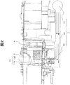
- FIG. 2 is a partial cross-sectional view of a liquid crystal projector. Sectional drawing of liquid crystal panel unit vicinity. The figure which shows the cooling air flow of liquid crystal panel unit vicinity. Sectional drawing of polarizing plate vicinity. The figure which shows the cooling air flow of polarizing plate vicinity.
- FIG. 1 is a block diagram of a liquid crystal projector and is shown with particular emphasis on its optical system.
- the light source unit 101 includes a tube 101a which is a light emitting portion and a reflector 101b which is a reflecting surface.
- the luminous flux emitted from the tube 101a disposed at the first focal position of the elliptical shaped reflector 101b is reflected from the reflecting surface so as to be condensed at the second focal position of the reflector 101b.
- the condensed luminous flux whose luminous flux size is reduced is converted into a collimated luminous flux by the concave lens 102 having a collimating action.
- the concave lens 102 for performing the parallelizing operation is not necessary.
- the parallel light beams emitted from the concave lens 102 are divided into partial light beams by the respective cell lenses of the first multi lens array 103 a and condensed on the respective cell lenses of the second multi lens array 103 b corresponding to the first multi lens.
- Ru The collected partial light fluxes are temporarily separated into two linearly polarized lights whose vibration directions are orthogonal to each other by the linear polarization unit 104, and the vibration direction of one linearly polarized light is matched with the other vibration direction.
- the vibration direction is converted to linear polarization in one direction.
- the partial light fluxes emitted from the linear polarization unit 104 are superimposed and irradiated onto the liquid crystal panel units 1R, 1G, and 1B for each color of RGB by the superimposing lens 105.
- reflection mirrors 106a, 106b, 106c, 106d for bending the light path and dichroic mirrors 107a and 107b as color separation optical units are provided.
- collimator lenses 108R, 108G, 108B for collimating the principal ray of the projected light beam are disposed in front of the liquid crystal panel units 1R, 1G, 1B.
- relay lenses 109 and 110 for mapping the superimposed light flux on the position of the liquid crystal panel unit 1R for red are disposed.
- the luminous flux from the tube 101a supplied to the liquid crystal panel units 1R, 1G, 1B is an image R signal, an image G signal, an image B signal separately supplied to each of the liquid crystal panel units 1R, 1G, 1B.
- the amount of light that can pass through the liquid crystal panel is changed according to the level of.
- the information of the video signal is given to the luminous flux.
- the liquid crystal panel units 1R, 1G, and 1B are provided not only with the liquid crystal panels but also with polarizing plates for passing light beams in a predetermined vibration direction.
- the respective light beams having passed through the liquid crystal panel units 1R, 1G, 1B are combined with each other by the cross prism 2, and an image according to the video signal is displayed on a screen (not shown) provided outside via the projection lens 3. Do.
- the liquid crystal panel units 1R, 1G, and 1B are components in which the change of the characteristics due to the adhesion of dust and the temperature change (especially, the temperature rise) becomes a problem. This characteristic change changes the brightness and color balance of the displayed image, and adversely affects the life. Therefore, the liquid crystal projector has a cooling mechanism for cooling the liquid crystal panel units 1R, 1G, and 1B.
- the cooling fan in the cooling mechanism cools the liquid crystal panel units 1R, 1G, and 1B by feeding air taken in from the outside of the liquid crystal projector in a direction substantially perpendicular to the paper surface of FIG. Next, the cooling mechanism will be described.
- FIG. 2 is a partial sketch of the liquid crystal projector.
- the liquid crystal panel unit shows only the liquid crystal panel unit 1G corresponding to the green light provided on the left side of the cross prism 2 in FIG. 2, but of course the liquid crystal corresponding to the blue light in front of the cross prism 2
- a panel unit 1B is provided on the opposite side of the cross prism 2 with a liquid crystal panel unit 1R corresponding to red light.
- the liquid crystal panel 11G and the polarizing plate 12G are shown with different reference numerals. In addition to these, FIG.
- the cooling unit 4 is schematically shown to avoid complication of the drawing.
- the cooling unit 4 includes a cooling air drive unit 41, a duct 42, and a cooling air blowing unit 43. Arrows in the figure indicate the flow of cooling air.
- the cooling air drive unit 41 of the cooling unit 4 includes, for example, a rotating fan, takes in air from the outside of the liquid crystal projector, and sends it to the duct 42 as cooling air in the left direction in the drawing.
- the cooling air delivered to the duct 42 reaches substantially below the liquid crystal panel unit 1G (1R, 1B)
- the direction is changed upward in the drawing, and the liquid crystal panel unit 1G (1R, 1B) Blow out from the bottom of the) toward the top.
- the temperature rise of the liquid crystal panel unit 1G (1R, 1B) can be suppressed, and the liquid crystal panel unit 1G (1R, 1B) can operate within the predetermined operation guaranteed temperature range.
- FIG. 3 is a partial cross-sectional view of the liquid crystal projector, showing a cross-sectional view from the liquid crystal panel unit to the periphery of the projection lens when viewed from diagonally above the left with respect to the block diagram of FIG. .
- the cooling air reaching substantially the lower portion of the liquid crystal panel unit 1G travels upward in the duct 42 in the drawing, and the liquid crystal panels 11G (11R, 11B) and the polarizing plates 12G (12R, 12B) from the cooling air outlet 43 Blow out toward the
- the cooling air contains fine dust taken from the outside air, and there is a problem that dust adheres to the surface of these components, particularly to the lower elongated surface in the drawing.
- the polarizing plate 12G (12R, 12B) is an aluminum grid inorganic polarizing plate and the dust deposited on the lower elongated surface (hereinafter referred to as the lower end surface) absorbs moisture
- the attached dust travels along the surface of the grid along the wire grooves constituting the grid and adheres in a streak shape, causing color unevenness in the projected image, and in the worst case, corroding the aluminum grid.
- a shade portion is provided on the lower side (cooling air blowing side) of the lower end of the polarizing plate 12G (12R, 12B) receiving the cooling air, and the polarizing plate 12G (12R, 12R, 12B) is characterized in that the amount of dust-containing cooling air directly received on the lower end face is reduced to prevent the adhesion of dust described above.
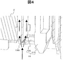
- FIG. 4 is a cross-sectional view in the vicinity of the liquid crystal panel unit, and shows a cross-sectional view in the vicinity of the lower part of the liquid crystal panel unit as viewed from the left side with respect to the block diagram of FIG.
- the cooling unit 4 sends the cooling air in a direction substantially orthogonal to the thickness direction of the polarizing plate 12G (12R, 12B), that is, a direction substantially orthogonal to the optical axis of the projection lens 3
- a shade member 13G (13R, 13B) is provided. Naturally, the amount of cooling air received is reduced over the entire lower surface of the polarizing plate 13G toward the front side and the depth side of the drawing.
- FIG. 5 is a view showing a cooling air flow in the vicinity of the liquid crystal panel unit, and shows a case where it is viewed from substantially the same direction as FIG. FIG. 5 shows simulation results on air flow.
- the cooling air flows along the wide surfaces of the liquid crystal panel 11 and the polarizing plate 12 so as to cool them.
- the cooling air is flowing so as not to directly hit the lower end surface of the polarizing plate 12 in particular. That is, when the shade member 13 is attached, there is a concern that the cooling effect originally required is reduced to cause the temperature rise of the liquid crystal panel unit 1G (1R, 1B), but this is not a problem here. It turns out that the goal can be achieved within the scope.
- conditions for flowing the cooling air so as not to directly hit the lower surface of the polarizing plate 12 are shown, as long as the cooling effect of the liquid crystal panel unit is not impaired.
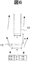
- FIG. 6 is a cross-sectional view of the vicinity of the polarizing plate.
- FIG. 6 shows a case where viewed from the same direction as FIG. 5, but in particular shows the vicinity of the shade member 13 in an enlarged manner.
- the width of the shade member 13 is a
- the distance from the polarizing plate 12 is b
- the thickness of the polarizing plate 12 is t.
- FIG. 6 is a view showing a cooling air flow near the polarizing plate, and shows three different examples. The example at the left end in the figure is the case where the shade member 13 has a round recess similar to FIG. 6, and the example at the center is the case where the cross section of the shade member 13 is V-shaped. Similar cooling air passes through.
- FIG. 6 An example of the right end is a case where the shade member 13 is provided to be inclined upward to the right in the drawing, and the cooling air passes mainly along the right side of the polarizing plate 12.
- the aluminum grid of the inorganic polarizing plate described above is provided on the surface on the left side in the drawing, that is, the surface facing the liquid crystal panel 11G (11R, 11B) described above.
- FIG. 6 the center of the cross section of the shade member 13 is slightly shifted to the left in the drawing than the center of the cross section of the polarizing plate 12, the same effect can be obtained by this arrangement method.
- the problem that fine dust contained in the cooling air adheres to the polarizing plate can be solved without impairing the cooling effect of the cooling air. Also, it is possible to provide a solution to the size of the shade member provided for that purpose.
- the embodiments described so far are examples and do not limit the present invention. For example, although different embodiments can be considered based on the gist of the present invention, such as an embodiment in which the direction of the cooling air flows is different, and an embodiment in which dust attached to components other than the polarizing plate is prevented. It is in the category.
Landscapes
- Physics & Mathematics (AREA)
- General Physics & Mathematics (AREA)
- Nonlinear Science (AREA)
- Optics & Photonics (AREA)
- Crystallography & Structural Chemistry (AREA)
- Chemical & Material Sciences (AREA)
- Mathematical Physics (AREA)
- Engineering & Computer Science (AREA)
- Multimedia (AREA)
- Signal Processing (AREA)
- Projection Apparatus (AREA)
- Transforming Electric Information Into Light Information (AREA)
- Liquid Crystal (AREA)
Abstract
Description
特許文献1においては、シロッコファンを用いた投射型液晶表示装置の冷却機構を開示している。
本発明の目的は前記した問題に鑑み、塵埃の付着を低減した液晶プロジェクタを提供することにある。
光を発生する光源部と、該光源部から供給された光が照射され該光を前記映像信号のレベルに応じて通過させる液晶パネルと偏光板を有する液晶パネルユニットと、該液晶パネルユニットを通過した光を外部に投射する投射レンズと、前記液晶パネルユニットを冷却するための冷却風を生成して前記液晶パネルユニットに送出する冷却部と、
該冷却部が前記液晶パネルユニットに前記冷却風を送出する側に面した、前記液晶パネルユニットの前記偏光板の一面に当たる前記冷却風を低減するためのシェード部材を有することを特徴としている。
図1は、液晶プロジェクタのブロック図であり、特にその光学系に重点を置いて示している。図1で、光源ユニット101は発光部である管球101aと反射面としてのリフレクタ101bを含んでいる。楕円形状のリフレクタ101bの第1焦点位置に配置された管球101aから出射された光束は、リフレクタ101bの第2焦点位置に集光するように前記反射面から反射される。光束サイズを縮小された集光光束は、平行化作用を有する凹レンズ102により平行光束に変換される。なお、リフレクタ101bを放物面形状とした場合は、平行化作用をするための凹レンズ102は不要となる。
液晶パネルユニット1R,1G,1Bを通過した各光束は、クロスプリズム2で互いに合成され、投射レンズ3を介して外部に設けられたスクリーン(図示せず)に前記映像信号に応じた映像を表示する。
該冷却機構における冷却ファンは、液晶プロジェクタの外部から取込んだ空気を、図1の紙面に対して略垂直な方向に送り込むことにより、液晶パネルユニット1R,1G,1Bを冷却している。次に冷却機構について説明する。
この問題を解消するため本実施例では、冷却風を受ける偏光板12G(12R,12B)の下端面の図面上で下側(冷却風吹出し側)にシェード部を設け、偏光板12G(12R、12B)の下端面に直接受ける塵埃を含んだ冷却風の量を低減して、前記した塵埃の付着を防ぐことを一つの特徴としている。
液晶パネルユニット1G(1R,1B)が有する偏光板12G(12R,12B)の図面上で下側には、偏光板12G(12R,12B)の下端面に直接受ける冷却風の量を低減するためのシェード部材13G(13R,13B)が設けられている。当然ながら図面の手前側や奥行側に向けて偏光板13Gの下側の面全般にわたって、受ける冷却風の量を低減するようにしている。
次に、液晶パネルユニットの冷却効果を損なわない範囲で、冷却風が偏光板12の下側の面に直接当たらないよう流れるための条件を示す。
0.9t≦ a ≦1.5t (式1)
0.5t≦ b ≦1.5t (式2)
図6において、シェード部材13は中央に窪みを持つ形状としているが、この形状に応じて冷却風の流れを変えることができる。
図7は、偏光板付近の冷却気流を示す図であり、3つの互いに異なる例を示している。図中で左端の例は、シェード部材13が図6と類似した丸い窪みを有する場合、中央の例はシェード部材13の断面がV字型の場合であって、ともに偏光板12の両側に沿って同程度の冷却風が通過する。
ここまで示した実施形態は一例であって、本発明を限定するものではない。例えば、冷却風を流す方向が異なる実施形態や、偏光板以外の構成要素に付着する塵埃を防ぐ実施形態をはじめ、本発明の趣旨に基づきながら異なる実施形態を考えられるが、いずれも本発明の範疇にある。
Claims (5)
- 供給された映像信号を液晶パネルユニットにおいて光信号に変換して投射する液晶プロジェクタであって、
光を発生する光源部と、
該光源部から供給された光が照射され該光を前記映像信号のレベルに応じて通過させる液晶パネルと偏光板を有する液晶パネルユニットと、
該液晶パネルユニットを通過した光を外部に投射する投射レンズと、
前記液晶パネルユニットを冷却するための冷却風を生成して前記液晶パネルユニットに送出する冷却部と、
該冷却部が前記液晶パネルユニットに前記冷却風を送出する側に面した、前記液晶パネルユニットの前記偏光板の一面に当たる前記冷却風を低減するためのシェード部材
を有することを特徴とする液晶プロジェクタ。 - 請求項1に記載の液晶プロジェクタにおいて、前記冷却部は、前記偏光板の厚さ方向に対して略直交する方向、即ち前記投射レンズの光軸に対して略直交する方向に前記冷却風を送出することを特徴とする液晶プロジェクタ。
- 請求項1に記載の液晶プロジェクタにおいて、前記偏光板は、無機偏光板であることを特徴とする液晶プロジェクタ。
- 請求項2に記載の液晶プロジェクタにおいて、前記シェード部材と偏光板は、前記偏光板の厚さをt、前記シェード部材における前記偏光板の厚さ方向の幅をa、前記シェード部材と前記偏光板の間の距離をbとした場合、
0.9t≦ a ≦1.5t
0.5t≦ b ≦1.5t
の関係にあることを特徴とする液晶プロジェクタ。 - 請求項3に記載の液晶プロジェクタにおいて、前記冷却風は、前記無機偏光板における偏光面とは逆の表面を主に冷却することを特徴とする液晶プロジェクタ。
Priority Applications (4)
| Application Number | Priority Date | Filing Date | Title |
|---|---|---|---|
| PCT/JP2011/052785 WO2012108019A1 (ja) | 2011-02-09 | 2011-02-09 | 液晶プロジェクタ |
| JP2012556702A JP5735549B2 (ja) | 2011-02-09 | 2011-02-09 | 液晶プロジェクタ |
| CN201180054255.0A CN103221885B (zh) | 2011-02-09 | 2011-02-09 | 液晶投影仪 |
| US13/883,773 US9185371B2 (en) | 2011-02-09 | 2011-02-09 | Liquid crystal projector having shade member preventing deterioration of polarizing plate |
Applications Claiming Priority (1)
| Application Number | Priority Date | Filing Date | Title |
|---|---|---|---|
| PCT/JP2011/052785 WO2012108019A1 (ja) | 2011-02-09 | 2011-02-09 | 液晶プロジェクタ |
Publications (1)
| Publication Number | Publication Date |
|---|---|
| WO2012108019A1 true WO2012108019A1 (ja) | 2012-08-16 |
Family
ID=46638262
Family Applications (1)
| Application Number | Title | Priority Date | Filing Date |
|---|---|---|---|
| PCT/JP2011/052785 Ceased WO2012108019A1 (ja) | 2011-02-09 | 2011-02-09 | 液晶プロジェクタ |
Country Status (4)
| Country | Link |
|---|---|
| US (1) | US9185371B2 (ja) |
| JP (1) | JP5735549B2 (ja) |
| CN (1) | CN103221885B (ja) |
| WO (1) | WO2012108019A1 (ja) |
Cited By (1)
| Publication number | Priority date | Publication date | Assignee | Title |
|---|---|---|---|---|
| WO2016125221A1 (ja) * | 2015-02-05 | 2016-08-11 | ソニー株式会社 | プロジェクタ及び光学ユニット |
Citations (7)
| Publication number | Priority date | Publication date | Assignee | Title |
|---|---|---|---|---|
| JPH0980374A (ja) * | 1995-09-12 | 1997-03-28 | Fujitsu Ltd | 光学装置及びそれを有する液晶プロジェクタ |
| JPH09197364A (ja) * | 1996-01-23 | 1997-07-31 | Fujitsu Ltd | 液晶プロジェクタ及び液晶プロジェクタの冷却方法 |
| JP2002318340A (ja) * | 2001-04-20 | 2002-10-31 | Fujitsu General Ltd | プリズムユニット |
| JP2003207639A (ja) * | 2002-01-16 | 2003-07-25 | Seiko Epson Corp | 偏光ユニット、この偏光ユニットを備える光学装置、およびプロジェクタ |
| JP2005195824A (ja) * | 2004-01-07 | 2005-07-21 | Asahi Kasei Chemicals Corp | ワイヤグリッド型偏光子 |
| JP2007033746A (ja) * | 2005-07-26 | 2007-02-08 | Seiko Epson Corp | 光学素子の製造方法、光学素子、投射型表示装置 |
| JP2009282416A (ja) * | 2008-05-26 | 2009-12-03 | Hitachi Ltd | 光学ユニットおよびそれを用いた投射型液晶表示装置 |
Family Cites Families (15)
| Publication number | Priority date | Publication date | Assignee | Title |
|---|---|---|---|---|
| JP2944354B2 (ja) * | 1993-03-30 | 1999-09-06 | 三洋電機株式会社 | 液晶プロジェクタ |
| US5892561A (en) * | 1995-10-18 | 1999-04-06 | Fujitsu Limited | LC panel with reduced defects having adhesive smoothing layer on an exterior surface of the substrate(s) |
| JP3397090B2 (ja) | 1997-08-04 | 2003-04-14 | 松下電器産業株式会社 | 投射型液晶表示装置 |
| US6919992B2 (en) * | 2001-10-01 | 2005-07-19 | Canon Kabushiki Kaisha | Color separating-combining optical system, image display optical system, and projection image display apparatus |
| JP4023179B2 (ja) * | 2002-02-21 | 2007-12-19 | ソニー株式会社 | 投射型表示装置 |
| US7118222B2 (en) * | 2003-05-12 | 2006-10-10 | Seiko Epson Corporation | Optical device and protector |
| JP4133774B2 (ja) * | 2003-12-02 | 2008-08-13 | Necディスプレイソリューションズ株式会社 | 液晶プロジェクタ装置および液晶プロジェクタ装置の冷却方法 |
| JP2005250061A (ja) * | 2004-03-03 | 2005-09-15 | Hitachi Ltd | 光学ユニット、投射型映像表示装置及びそれに用いる光学素子 |
| JP4492174B2 (ja) * | 2004-03-26 | 2010-06-30 | 株式会社日立製作所 | 液晶表示装置 |
| JP4096904B2 (ja) * | 2004-03-26 | 2008-06-04 | セイコーエプソン株式会社 | 光変調素子保持体、光学装置、およびプロジェクタ |
| JP2005266833A (ja) * | 2005-06-13 | 2005-09-29 | Hitachi Ltd | 映像表示装置 |
| US20070002191A1 (en) * | 2005-07-01 | 2007-01-04 | Seiko Epson Corporation | Projector |
| JP5268506B2 (ja) * | 2008-09-05 | 2013-08-21 | 三洋電機株式会社 | 投写型映像表示装置 |
| JP5161810B2 (ja) * | 2009-02-25 | 2013-03-13 | 株式会社日立製作所 | 光学ユニットおよびそれを用いた投射型液晶表示装置 |
| JP2011141395A (ja) * | 2010-01-06 | 2011-07-21 | Sanyo Electric Co Ltd | 投写型映像表示装置 |
-
2011
- 2011-02-09 US US13/883,773 patent/US9185371B2/en not_active Expired - Fee Related
- 2011-02-09 WO PCT/JP2011/052785 patent/WO2012108019A1/ja not_active Ceased
- 2011-02-09 JP JP2012556702A patent/JP5735549B2/ja not_active Expired - Fee Related
- 2011-02-09 CN CN201180054255.0A patent/CN103221885B/zh not_active Expired - Fee Related
Patent Citations (7)
| Publication number | Priority date | Publication date | Assignee | Title |
|---|---|---|---|---|
| JPH0980374A (ja) * | 1995-09-12 | 1997-03-28 | Fujitsu Ltd | 光学装置及びそれを有する液晶プロジェクタ |
| JPH09197364A (ja) * | 1996-01-23 | 1997-07-31 | Fujitsu Ltd | 液晶プロジェクタ及び液晶プロジェクタの冷却方法 |
| JP2002318340A (ja) * | 2001-04-20 | 2002-10-31 | Fujitsu General Ltd | プリズムユニット |
| JP2003207639A (ja) * | 2002-01-16 | 2003-07-25 | Seiko Epson Corp | 偏光ユニット、この偏光ユニットを備える光学装置、およびプロジェクタ |
| JP2005195824A (ja) * | 2004-01-07 | 2005-07-21 | Asahi Kasei Chemicals Corp | ワイヤグリッド型偏光子 |
| JP2007033746A (ja) * | 2005-07-26 | 2007-02-08 | Seiko Epson Corp | 光学素子の製造方法、光学素子、投射型表示装置 |
| JP2009282416A (ja) * | 2008-05-26 | 2009-12-03 | Hitachi Ltd | 光学ユニットおよびそれを用いた投射型液晶表示装置 |
Cited By (3)
| Publication number | Priority date | Publication date | Assignee | Title |
|---|---|---|---|---|
| WO2016125221A1 (ja) * | 2015-02-05 | 2016-08-11 | ソニー株式会社 | プロジェクタ及び光学ユニット |
| JPWO2016125221A1 (ja) * | 2015-02-05 | 2017-11-09 | ソニー株式会社 | プロジェクタ及び光学ユニット |
| US10511814B2 (en) | 2015-02-05 | 2019-12-17 | Sony Corporation | Projector and optical unit |
Also Published As
| Publication number | Publication date |
|---|---|
| JP5735549B2 (ja) | 2015-06-17 |
| US9185371B2 (en) | 2015-11-10 |
| US20140009698A1 (en) | 2014-01-09 |
| JPWO2012108019A1 (ja) | 2014-07-03 |
| CN103221885A (zh) | 2013-07-24 |
| CN103221885B (zh) | 2015-07-29 |
Similar Documents
| Publication | Publication Date | Title |
|---|---|---|
| US7524084B2 (en) | Illuminating device, and projection type video display | |
| JP4901595B2 (ja) | 投写型表示装置 | |
| WO2004072726A1 (ja) | 光学部品用筐体、及びプロジェクタ | |
| US20140375966A1 (en) | Cooling device, image projection apparatus, and electronic apparatus | |
| JP4017167B2 (ja) | 投映表示装置 | |
| JP2007256899A (ja) | プロジェクタ | |
| CN103959163B (zh) | 投影型影像显示装置 | |
| JP5735549B2 (ja) | 液晶プロジェクタ | |
| CN101666965A (zh) | 投影型图像显示装置 | |
| JP5453957B2 (ja) | 光学装置およびプロジェクター | |
| JP2011075763A (ja) | 投写型映像表示装置 | |
| JP2005121900A (ja) | 投射型表示装置、および、投射型表示装置用の光学系 | |
| JP4166217B2 (ja) | 照明装置及び投写型映像表示装置 | |
| JP5938929B2 (ja) | プロジェクター | |
| JP2016126205A (ja) | プロジェクター | |
| JP5793999B2 (ja) | プロジェクター | |
| JP5900008B2 (ja) | プロジェクター | |
| JP2011028089A (ja) | 液晶表示装置および投射型表示装置 | |
| JP4806912B2 (ja) | 画像投射装置 | |
| JPWO2019146080A1 (ja) | 投写型映像表示装置 | |
| WO2016021032A1 (ja) | 投射型表示装置 | |
| JP4595441B2 (ja) | プロジェクタ | |
| JP5035399B2 (ja) | プロジェクタ | |
| JP2006058816A (ja) | 投写型映像表示装置 | |
| JP2013007972A (ja) | 投写型映像表示装置及びランプユニット |
Legal Events
| Date | Code | Title | Description |
|---|---|---|---|
| 121 | Ep: the epo has been informed by wipo that ep was designated in this application |
Ref document number: 11858344 Country of ref document: EP Kind code of ref document: A1 |
|
| WWE | Wipo information: entry into national phase |
Ref document number: 13883773 Country of ref document: US |
|
| ENP | Entry into the national phase |
Ref document number: 2012556702 Country of ref document: JP Kind code of ref document: A |
|
| NENP | Non-entry into the national phase |
Ref country code: DE |
|
| 122 | Ep: pct application non-entry in european phase |
Ref document number: 11858344 Country of ref document: EP Kind code of ref document: A1 |