WO2012105717A1 - 車両骨格部材 - Google Patents
車両骨格部材 Download PDFInfo
- Publication number
- WO2012105717A1 WO2012105717A1 PCT/JP2012/052797 JP2012052797W WO2012105717A1 WO 2012105717 A1 WO2012105717 A1 WO 2012105717A1 JP 2012052797 W JP2012052797 W JP 2012052797W WO 2012105717 A1 WO2012105717 A1 WO 2012105717A1
- Authority
- WO
- WIPO (PCT)
- Prior art keywords
- vehicle
- fastening
- fiber
- skeleton member
- composite material
- Prior art date
Links
- 239000002131 composite material Substances 0.000 claims abstract description 31
- 229920005992 thermoplastic resin Polymers 0.000 claims abstract description 16
- 239000012783 reinforcing fiber Substances 0.000 claims abstract description 14
- 229920000049 Carbon (fiber) Polymers 0.000 claims description 5
- 239000004917 carbon fiber Substances 0.000 claims description 5
- VNWKTOKETHGBQD-UHFFFAOYSA-N methane Chemical group C VNWKTOKETHGBQD-UHFFFAOYSA-N 0.000 claims description 5
- 238000003466 welding Methods 0.000 abstract description 43
- 239000000835 fiber Substances 0.000 description 28
- 238000000034 method Methods 0.000 description 26
- 239000000463 material Substances 0.000 description 23
- 229920005989 resin Polymers 0.000 description 21
- 239000011347 resin Substances 0.000 description 21
- 239000003733 fiber-reinforced composite Substances 0.000 description 19
- 238000010586 diagram Methods 0.000 description 9
- 239000011159 matrix material Substances 0.000 description 5
- 229910000831 Steel Inorganic materials 0.000 description 4
- 238000005304 joining Methods 0.000 description 4
- 239000002184 metal Substances 0.000 description 4
- 229910052751 metal Inorganic materials 0.000 description 4
- 239000010959 steel Substances 0.000 description 4
- 239000002759 woven fabric Substances 0.000 description 4
- 239000000853 adhesive Substances 0.000 description 3
- 230000001070 adhesive effect Effects 0.000 description 3
- 238000004519 manufacturing process Methods 0.000 description 3
- 229920001169 thermoplastic Polymers 0.000 description 3
- 239000004416 thermosoftening plastic Substances 0.000 description 3
- 239000004697 Polyetherimide Substances 0.000 description 2
- KAESVJOAVNADME-UHFFFAOYSA-N Pyrrole Chemical compound C=1C=CNC=1 KAESVJOAVNADME-UHFFFAOYSA-N 0.000 description 2
- 238000005516 engineering process Methods 0.000 description 2
- 239000004744 fabric Substances 0.000 description 2
- 239000003365 glass fiber Substances 0.000 description 2
- 229920000728 polyester Polymers 0.000 description 2
- 229920001601 polyetherimide Polymers 0.000 description 2
- 229920001187 thermosetting polymer Polymers 0.000 description 2
- 239000013585 weight reducing agent Substances 0.000 description 2
- 229920000178 Acrylic resin Polymers 0.000 description 1
- 239000004925 Acrylic resin Substances 0.000 description 1
- ZOXJGFHDIHLPTG-UHFFFAOYSA-N Boron Chemical compound [B] ZOXJGFHDIHLPTG-UHFFFAOYSA-N 0.000 description 1
- OKTJSMMVPCPJKN-UHFFFAOYSA-N Carbon Chemical compound [C] OKTJSMMVPCPJKN-UHFFFAOYSA-N 0.000 description 1
- 239000004677 Nylon Substances 0.000 description 1
- 239000004696 Poly ether ether ketone Substances 0.000 description 1
- 239000004962 Polyamide-imide Substances 0.000 description 1
- 239000004695 Polyether sulfone Substances 0.000 description 1
- 229920000265 Polyparaphenylene Polymers 0.000 description 1
- 239000004734 Polyphenylene sulfide Substances 0.000 description 1
- 229920002877 acrylic styrene acrylonitrile Polymers 0.000 description 1
- 229920000122 acrylonitrile butadiene styrene Polymers 0.000 description 1
- PNEYBMLMFCGWSK-UHFFFAOYSA-N aluminium oxide Inorganic materials [O-2].[O-2].[O-2].[Al+3].[Al+3] PNEYBMLMFCGWSK-UHFFFAOYSA-N 0.000 description 1
- 229920006231 aramid fiber Polymers 0.000 description 1
- 229920003235 aromatic polyamide Polymers 0.000 description 1
- 238000011074 autoclave method Methods 0.000 description 1
- 230000037396 body weight Effects 0.000 description 1
- 229910052796 boron Inorganic materials 0.000 description 1
- 229910052799 carbon Inorganic materials 0.000 description 1
- 239000000919 ceramic Substances 0.000 description 1
- 230000007613 environmental effect Effects 0.000 description 1
- 238000001125 extrusion Methods 0.000 description 1
- 238000009787 hand lay-up Methods 0.000 description 1
- 239000002648 laminated material Substances 0.000 description 1
- 238000002844 melting Methods 0.000 description 1
- 230000008018 melting Effects 0.000 description 1
- 150000002739 metals Chemical class 0.000 description 1
- 239000000203 mixture Substances 0.000 description 1
- 239000004745 nonwoven fabric Substances 0.000 description 1
- 229920001778 nylon Polymers 0.000 description 1
- 229920001643 poly(ether ketone) Polymers 0.000 description 1
- 229920000747 poly(lactic acid) Polymers 0.000 description 1
- 229920002492 poly(sulfone) Polymers 0.000 description 1
- 229920006122 polyamide resin Polymers 0.000 description 1
- 229920002312 polyamide-imide Polymers 0.000 description 1
- 229920005668 polycarbonate resin Polymers 0.000 description 1
- 239000004431 polycarbonate resin Substances 0.000 description 1
- 229920001225 polyester resin Polymers 0.000 description 1
- 239000004645 polyester resin Substances 0.000 description 1
- 229920006393 polyether sulfone Polymers 0.000 description 1
- 229920002530 polyetherether ketone Polymers 0.000 description 1
- 239000004626 polylactic acid Substances 0.000 description 1
- 229920000098 polyolefin Polymers 0.000 description 1
- 229920005672 polyolefin resin Polymers 0.000 description 1
- -1 polyphenylene Polymers 0.000 description 1
- 229920001955 polyphenylene ether Polymers 0.000 description 1
- 229920000069 polyphenylene sulfide Polymers 0.000 description 1
- 230000035484 reaction time Effects 0.000 description 1
- 238000003303 reheating Methods 0.000 description 1
- 230000002787 reinforcement Effects 0.000 description 1
- 230000003014 reinforcing effect Effects 0.000 description 1
- 239000011342 resin composition Substances 0.000 description 1
- 230000000630 rising effect Effects 0.000 description 1
- 238000001721 transfer moulding Methods 0.000 description 1
Images


Classifications
-
- B—PERFORMING OPERATIONS; TRANSPORTING
- B62—LAND VEHICLES FOR TRAVELLING OTHERWISE THAN ON RAILS
- B62D—MOTOR VEHICLES; TRAILERS
- B62D29/00—Superstructures, understructures, or sub-units thereof, characterised by the material thereof
- B62D29/04—Superstructures, understructures, or sub-units thereof, characterised by the material thereof predominantly of synthetic material
-
- B—PERFORMING OPERATIONS; TRANSPORTING
- B62—LAND VEHICLES FOR TRAVELLING OTHERWISE THAN ON RAILS
- B62D—MOTOR VEHICLES; TRAILERS
- B62D25/00—Superstructure or monocoque structure sub-units; Parts or details thereof not otherwise provided for
-
- B—PERFORMING OPERATIONS; TRANSPORTING
- B29—WORKING OF PLASTICS; WORKING OF SUBSTANCES IN A PLASTIC STATE IN GENERAL
- B29C—SHAPING OR JOINING OF PLASTICS; SHAPING OF MATERIAL IN A PLASTIC STATE, NOT OTHERWISE PROVIDED FOR; AFTER-TREATMENT OF THE SHAPED PRODUCTS, e.g. REPAIRING
- B29C65/00—Joining or sealing of preformed parts, e.g. welding of plastics materials; Apparatus therefor
- B29C65/02—Joining or sealing of preformed parts, e.g. welding of plastics materials; Apparatus therefor by heating, with or without pressure
- B29C65/06—Joining or sealing of preformed parts, e.g. welding of plastics materials; Apparatus therefor by heating, with or without pressure using friction, e.g. spin welding
- B29C65/0609—Joining or sealing of preformed parts, e.g. welding of plastics materials; Apparatus therefor by heating, with or without pressure using friction, e.g. spin welding characterised by the movement of the parts to be joined
- B29C65/0618—Linear
-
- B—PERFORMING OPERATIONS; TRANSPORTING
- B29—WORKING OF PLASTICS; WORKING OF SUBSTANCES IN A PLASTIC STATE IN GENERAL
- B29C—SHAPING OR JOINING OF PLASTICS; SHAPING OF MATERIAL IN A PLASTIC STATE, NOT OTHERWISE PROVIDED FOR; AFTER-TREATMENT OF THE SHAPED PRODUCTS, e.g. REPAIRING
- B29C66/00—General aspects of processes or apparatus for joining preformed parts
- B29C66/01—General aspects dealing with the joint area or with the area to be joined
- B29C66/05—Particular design of joint configurations
- B29C66/10—Particular design of joint configurations particular design of the joint cross-sections
- B29C66/11—Joint cross-sections comprising a single joint-segment, i.e. one of the parts to be joined comprising a single joint-segment in the joint cross-section
- B29C66/112—Single lapped joints
-
- B—PERFORMING OPERATIONS; TRANSPORTING
- B29—WORKING OF PLASTICS; WORKING OF SUBSTANCES IN A PLASTIC STATE IN GENERAL
- B29C—SHAPING OR JOINING OF PLASTICS; SHAPING OF MATERIAL IN A PLASTIC STATE, NOT OTHERWISE PROVIDED FOR; AFTER-TREATMENT OF THE SHAPED PRODUCTS, e.g. REPAIRING
- B29C66/00—General aspects of processes or apparatus for joining preformed parts
- B29C66/01—General aspects dealing with the joint area or with the area to be joined
- B29C66/05—Particular design of joint configurations
- B29C66/10—Particular design of joint configurations particular design of the joint cross-sections
- B29C66/13—Single flanged joints; Fin-type joints; Single hem joints; Edge joints; Interpenetrating fingered joints; Other specific particular designs of joint cross-sections not provided for in groups B29C66/11 - B29C66/12
- B29C66/131—Single flanged joints, i.e. one of the parts to be joined being rigid and flanged in the joint area
- B29C66/1312—Single flange to flange joints, the parts to be joined being rigid
-
- B—PERFORMING OPERATIONS; TRANSPORTING
- B29—WORKING OF PLASTICS; WORKING OF SUBSTANCES IN A PLASTIC STATE IN GENERAL
- B29C—SHAPING OR JOINING OF PLASTICS; SHAPING OF MATERIAL IN A PLASTIC STATE, NOT OTHERWISE PROVIDED FOR; AFTER-TREATMENT OF THE SHAPED PRODUCTS, e.g. REPAIRING
- B29C66/00—General aspects of processes or apparatus for joining preformed parts
- B29C66/50—General aspects of joining tubular articles; General aspects of joining long products, i.e. bars or profiled elements; General aspects of joining single elements to tubular articles, hollow articles or bars; General aspects of joining several hollow-preforms to form hollow or tubular articles
- B29C66/51—Joining tubular articles, profiled elements or bars; Joining single elements to tubular articles, hollow articles or bars; Joining several hollow-preforms to form hollow or tubular articles
- B29C66/52—Joining tubular articles, bars or profiled elements
- B29C66/524—Joining profiled elements
-
- B—PERFORMING OPERATIONS; TRANSPORTING
- B29—WORKING OF PLASTICS; WORKING OF SUBSTANCES IN A PLASTIC STATE IN GENERAL
- B29C—SHAPING OR JOINING OF PLASTICS; SHAPING OF MATERIAL IN A PLASTIC STATE, NOT OTHERWISE PROVIDED FOR; AFTER-TREATMENT OF THE SHAPED PRODUCTS, e.g. REPAIRING
- B29C66/00—General aspects of processes or apparatus for joining preformed parts
- B29C66/50—General aspects of joining tubular articles; General aspects of joining long products, i.e. bars or profiled elements; General aspects of joining single elements to tubular articles, hollow articles or bars; General aspects of joining several hollow-preforms to form hollow or tubular articles
- B29C66/51—Joining tubular articles, profiled elements or bars; Joining single elements to tubular articles, hollow articles or bars; Joining several hollow-preforms to form hollow or tubular articles
- B29C66/53—Joining single elements to tubular articles, hollow articles or bars
- B29C66/534—Joining single elements to open ends of tubular or hollow articles or to the ends of bars
-
- B—PERFORMING OPERATIONS; TRANSPORTING
- B29—WORKING OF PLASTICS; WORKING OF SUBSTANCES IN A PLASTIC STATE IN GENERAL
- B29C—SHAPING OR JOINING OF PLASTICS; SHAPING OF MATERIAL IN A PLASTIC STATE, NOT OTHERWISE PROVIDED FOR; AFTER-TREATMENT OF THE SHAPED PRODUCTS, e.g. REPAIRING
- B29C66/00—General aspects of processes or apparatus for joining preformed parts
- B29C66/50—General aspects of joining tubular articles; General aspects of joining long products, i.e. bars or profiled elements; General aspects of joining single elements to tubular articles, hollow articles or bars; General aspects of joining several hollow-preforms to form hollow or tubular articles
- B29C66/51—Joining tubular articles, profiled elements or bars; Joining single elements to tubular articles, hollow articles or bars; Joining several hollow-preforms to form hollow or tubular articles
- B29C66/54—Joining several hollow-preforms, e.g. half-shells, to form hollow articles, e.g. for making balls, containers; Joining several hollow-preforms, e.g. half-cylinders, to form tubular articles
- B29C66/541—Joining several hollow-preforms, e.g. half-shells, to form hollow articles, e.g. for making balls, containers; Joining several hollow-preforms, e.g. half-cylinders, to form tubular articles a substantially flat extra element being placed between and clamped by the joined hollow-preforms
- B29C66/5414—Joining several hollow-preforms, e.g. half-shells, to form hollow articles, e.g. for making balls, containers; Joining several hollow-preforms, e.g. half-cylinders, to form tubular articles a substantially flat extra element being placed between and clamped by the joined hollow-preforms said substantially flat extra element being rigid, e.g. a plate
-
- B—PERFORMING OPERATIONS; TRANSPORTING
- B29—WORKING OF PLASTICS; WORKING OF SUBSTANCES IN A PLASTIC STATE IN GENERAL
- B29C—SHAPING OR JOINING OF PLASTICS; SHAPING OF MATERIAL IN A PLASTIC STATE, NOT OTHERWISE PROVIDED FOR; AFTER-TREATMENT OF THE SHAPED PRODUCTS, e.g. REPAIRING
- B29C66/00—General aspects of processes or apparatus for joining preformed parts
- B29C66/50—General aspects of joining tubular articles; General aspects of joining long products, i.e. bars or profiled elements; General aspects of joining single elements to tubular articles, hollow articles or bars; General aspects of joining several hollow-preforms to form hollow or tubular articles
- B29C66/51—Joining tubular articles, profiled elements or bars; Joining single elements to tubular articles, hollow articles or bars; Joining several hollow-preforms to form hollow or tubular articles
- B29C66/54—Joining several hollow-preforms, e.g. half-shells, to form hollow articles, e.g. for making balls, containers; Joining several hollow-preforms, e.g. half-cylinders, to form tubular articles
- B29C66/543—Joining several hollow-preforms, e.g. half-shells, to form hollow articles, e.g. for making balls, containers; Joining several hollow-preforms, e.g. half-cylinders, to form tubular articles joining more than two hollow-preforms to form said hollow articles
-
- B—PERFORMING OPERATIONS; TRANSPORTING
- B29—WORKING OF PLASTICS; WORKING OF SUBSTANCES IN A PLASTIC STATE IN GENERAL
- B29C—SHAPING OR JOINING OF PLASTICS; SHAPING OF MATERIAL IN A PLASTIC STATE, NOT OTHERWISE PROVIDED FOR; AFTER-TREATMENT OF THE SHAPED PRODUCTS, e.g. REPAIRING
- B29C66/00—General aspects of processes or apparatus for joining preformed parts
- B29C66/50—General aspects of joining tubular articles; General aspects of joining long products, i.e. bars or profiled elements; General aspects of joining single elements to tubular articles, hollow articles or bars; General aspects of joining several hollow-preforms to form hollow or tubular articles
- B29C66/51—Joining tubular articles, profiled elements or bars; Joining single elements to tubular articles, hollow articles or bars; Joining several hollow-preforms to form hollow or tubular articles
- B29C66/54—Joining several hollow-preforms, e.g. half-shells, to form hollow articles, e.g. for making balls, containers; Joining several hollow-preforms, e.g. half-cylinders, to form tubular articles
- B29C66/545—Joining several hollow-preforms, e.g. half-shells, to form hollow articles, e.g. for making balls, containers; Joining several hollow-preforms, e.g. half-cylinders, to form tubular articles one hollow-preform being placed inside the other
-
- B—PERFORMING OPERATIONS; TRANSPORTING
- B29—WORKING OF PLASTICS; WORKING OF SUBSTANCES IN A PLASTIC STATE IN GENERAL
- B29C—SHAPING OR JOINING OF PLASTICS; SHAPING OF MATERIAL IN A PLASTIC STATE, NOT OTHERWISE PROVIDED FOR; AFTER-TREATMENT OF THE SHAPED PRODUCTS, e.g. REPAIRING
- B29C66/00—General aspects of processes or apparatus for joining preformed parts
- B29C66/70—General aspects of processes or apparatus for joining preformed parts characterised by the composition, physical properties or the structure of the material of the parts to be joined; Joining with non-plastics material
- B29C66/72—General aspects of processes or apparatus for joining preformed parts characterised by the composition, physical properties or the structure of the material of the parts to be joined; Joining with non-plastics material characterised by the structure of the material of the parts to be joined
- B29C66/721—Fibre-reinforced materials
- B29C66/7212—Fibre-reinforced materials characterised by the composition of the fibres
-
- B—PERFORMING OPERATIONS; TRANSPORTING
- B29—WORKING OF PLASTICS; WORKING OF SUBSTANCES IN A PLASTIC STATE IN GENERAL
- B29C—SHAPING OR JOINING OF PLASTICS; SHAPING OF MATERIAL IN A PLASTIC STATE, NOT OTHERWISE PROVIDED FOR; AFTER-TREATMENT OF THE SHAPED PRODUCTS, e.g. REPAIRING
- B29C66/00—General aspects of processes or apparatus for joining preformed parts
- B29C66/70—General aspects of processes or apparatus for joining preformed parts characterised by the composition, physical properties or the structure of the material of the parts to be joined; Joining with non-plastics material
- B29C66/73—General aspects of processes or apparatus for joining preformed parts characterised by the composition, physical properties or the structure of the material of the parts to be joined; Joining with non-plastics material characterised by the intensive physical properties of the material of the parts to be joined, by the optical properties of the material of the parts to be joined, by the extensive physical properties of the parts to be joined, by the state of the material of the parts to be joined or by the material of the parts to be joined being a thermoplastic or a thermoset
- B29C66/739—General aspects of processes or apparatus for joining preformed parts characterised by the composition, physical properties or the structure of the material of the parts to be joined; Joining with non-plastics material characterised by the intensive physical properties of the material of the parts to be joined, by the optical properties of the material of the parts to be joined, by the extensive physical properties of the parts to be joined, by the state of the material of the parts to be joined or by the material of the parts to be joined being a thermoplastic or a thermoset characterised by the material of the parts to be joined being a thermoplastic or a thermoset
- B29C66/7392—General aspects of processes or apparatus for joining preformed parts characterised by the composition, physical properties or the structure of the material of the parts to be joined; Joining with non-plastics material characterised by the intensive physical properties of the material of the parts to be joined, by the optical properties of the material of the parts to be joined, by the extensive physical properties of the parts to be joined, by the state of the material of the parts to be joined or by the material of the parts to be joined being a thermoplastic or a thermoset characterised by the material of the parts to be joined being a thermoplastic or a thermoset characterised by the material of at least one of the parts being a thermoplastic
- B29C66/73921—General aspects of processes or apparatus for joining preformed parts characterised by the composition, physical properties or the structure of the material of the parts to be joined; Joining with non-plastics material characterised by the intensive physical properties of the material of the parts to be joined, by the optical properties of the material of the parts to be joined, by the extensive physical properties of the parts to be joined, by the state of the material of the parts to be joined or by the material of the parts to be joined being a thermoplastic or a thermoset characterised by the material of the parts to be joined being a thermoplastic or a thermoset characterised by the material of at least one of the parts being a thermoplastic characterised by the materials of both parts being thermoplastics
-
- B—PERFORMING OPERATIONS; TRANSPORTING
- B62—LAND VEHICLES FOR TRAVELLING OTHERWISE THAN ON RAILS
- B62D—MOTOR VEHICLES; TRAILERS
- B62D25/00—Superstructure or monocoque structure sub-units; Parts or details thereof not otherwise provided for
- B62D25/02—Side panels
- B62D25/025—Side sills thereof
-
- B—PERFORMING OPERATIONS; TRANSPORTING
- B62—LAND VEHICLES FOR TRAVELLING OTHERWISE THAN ON RAILS
- B62D—MOTOR VEHICLES; TRAILERS
- B62D25/00—Superstructure or monocoque structure sub-units; Parts or details thereof not otherwise provided for
- B62D25/04—Door pillars ; windshield pillars
-
- B—PERFORMING OPERATIONS; TRANSPORTING
- B62—LAND VEHICLES FOR TRAVELLING OTHERWISE THAN ON RAILS
- B62D—MOTOR VEHICLES; TRAILERS
- B62D25/00—Superstructure or monocoque structure sub-units; Parts or details thereof not otherwise provided for
- B62D25/06—Fixed roofs
-
- B—PERFORMING OPERATIONS; TRANSPORTING
- B62—LAND VEHICLES FOR TRAVELLING OTHERWISE THAN ON RAILS
- B62D—MOTOR VEHICLES; TRAILERS
- B62D25/00—Superstructure or monocoque structure sub-units; Parts or details thereof not otherwise provided for
- B62D25/20—Floors or bottom sub-units
-
- B—PERFORMING OPERATIONS; TRANSPORTING
- B62—LAND VEHICLES FOR TRAVELLING OTHERWISE THAN ON RAILS
- B62D—MOTOR VEHICLES; TRAILERS
- B62D25/00—Superstructure or monocoque structure sub-units; Parts or details thereof not otherwise provided for
- B62D25/20—Floors or bottom sub-units
- B62D25/2009—Floors or bottom sub-units in connection with other superstructure subunits
- B62D25/2036—Floors or bottom sub-units in connection with other superstructure subunits the subunits being side panels, sills or pillars
-
- B—PERFORMING OPERATIONS; TRANSPORTING
- B62—LAND VEHICLES FOR TRAVELLING OTHERWISE THAN ON RAILS
- B62D—MOTOR VEHICLES; TRAILERS
- B62D29/00—Superstructures, understructures, or sub-units thereof, characterised by the material thereof
- B62D29/04—Superstructures, understructures, or sub-units thereof, characterised by the material thereof predominantly of synthetic material
- B62D29/046—Combined superstructure and frame, i.e. monocoque constructions
-
- B—PERFORMING OPERATIONS; TRANSPORTING
- B62—LAND VEHICLES FOR TRAVELLING OTHERWISE THAN ON RAILS
- B62D—MOTOR VEHICLES; TRAILERS
- B62D29/00—Superstructures, understructures, or sub-units thereof, characterised by the material thereof
- B62D29/04—Superstructures, understructures, or sub-units thereof, characterised by the material thereof predominantly of synthetic material
- B62D29/048—Connections therefor, e.g. joints
-
- B—PERFORMING OPERATIONS; TRANSPORTING
- B29—WORKING OF PLASTICS; WORKING OF SUBSTANCES IN A PLASTIC STATE IN GENERAL
- B29C—SHAPING OR JOINING OF PLASTICS; SHAPING OF MATERIAL IN A PLASTIC STATE, NOT OTHERWISE PROVIDED FOR; AFTER-TREATMENT OF THE SHAPED PRODUCTS, e.g. REPAIRING
- B29C66/00—General aspects of processes or apparatus for joining preformed parts
- B29C66/70—General aspects of processes or apparatus for joining preformed parts characterised by the composition, physical properties or the structure of the material of the parts to be joined; Joining with non-plastics material
- B29C66/71—General aspects of processes or apparatus for joining preformed parts characterised by the composition, physical properties or the structure of the material of the parts to be joined; Joining with non-plastics material characterised by the composition of the plastics material of the parts to be joined
-
- B—PERFORMING OPERATIONS; TRANSPORTING
- B29—WORKING OF PLASTICS; WORKING OF SUBSTANCES IN A PLASTIC STATE IN GENERAL
- B29C—SHAPING OR JOINING OF PLASTICS; SHAPING OF MATERIAL IN A PLASTIC STATE, NOT OTHERWISE PROVIDED FOR; AFTER-TREATMENT OF THE SHAPED PRODUCTS, e.g. REPAIRING
- B29C66/00—General aspects of processes or apparatus for joining preformed parts
- B29C66/70—General aspects of processes or apparatus for joining preformed parts characterised by the composition, physical properties or the structure of the material of the parts to be joined; Joining with non-plastics material
- B29C66/72—General aspects of processes or apparatus for joining preformed parts characterised by the composition, physical properties or the structure of the material of the parts to be joined; Joining with non-plastics material characterised by the structure of the material of the parts to be joined
- B29C66/721—Fibre-reinforced materials
- B29C66/7214—Fibre-reinforced materials characterised by the length of the fibres
- B29C66/72141—Fibres of continuous length
-
- B—PERFORMING OPERATIONS; TRANSPORTING
- B29—WORKING OF PLASTICS; WORKING OF SUBSTANCES IN A PLASTIC STATE IN GENERAL
- B29C—SHAPING OR JOINING OF PLASTICS; SHAPING OF MATERIAL IN A PLASTIC STATE, NOT OTHERWISE PROVIDED FOR; AFTER-TREATMENT OF THE SHAPED PRODUCTS, e.g. REPAIRING
- B29C66/00—General aspects of processes or apparatus for joining preformed parts
- B29C66/70—General aspects of processes or apparatus for joining preformed parts characterised by the composition, physical properties or the structure of the material of the parts to be joined; Joining with non-plastics material
- B29C66/72—General aspects of processes or apparatus for joining preformed parts characterised by the composition, physical properties or the structure of the material of the parts to be joined; Joining with non-plastics material characterised by the structure of the material of the parts to be joined
- B29C66/721—Fibre-reinforced materials
- B29C66/7214—Fibre-reinforced materials characterised by the length of the fibres
- B29C66/72143—Fibres of discontinuous lengths
-
- B—PERFORMING OPERATIONS; TRANSPORTING
- B29—WORKING OF PLASTICS; WORKING OF SUBSTANCES IN A PLASTIC STATE IN GENERAL
- B29C—SHAPING OR JOINING OF PLASTICS; SHAPING OF MATERIAL IN A PLASTIC STATE, NOT OTHERWISE PROVIDED FOR; AFTER-TREATMENT OF THE SHAPED PRODUCTS, e.g. REPAIRING
- B29C66/00—General aspects of processes or apparatus for joining preformed parts
- B29C66/80—General aspects of machine operations or constructions and parts thereof
- B29C66/83—General aspects of machine operations or constructions and parts thereof characterised by the movement of the joining or pressing tools
- B29C66/832—Reciprocating joining or pressing tools
- B29C66/8322—Joining or pressing tools reciprocating along one axis
-
- B—PERFORMING OPERATIONS; TRANSPORTING
- B29—WORKING OF PLASTICS; WORKING OF SUBSTANCES IN A PLASTIC STATE IN GENERAL
- B29L—INDEXING SCHEME ASSOCIATED WITH SUBCLASS B29C, RELATING TO PARTICULAR ARTICLES
- B29L2012/00—Frames
-
- B—PERFORMING OPERATIONS; TRANSPORTING
- B29—WORKING OF PLASTICS; WORKING OF SUBSTANCES IN A PLASTIC STATE IN GENERAL
- B29L—INDEXING SCHEME ASSOCIATED WITH SUBCLASS B29C, RELATING TO PARTICULAR ARTICLES
- B29L2031/00—Other particular articles
- B29L2031/30—Vehicles, e.g. ships or aircraft, or body parts thereof
- B29L2031/3055—Cars
Definitions
- the present invention relates to a vehicle skeleton member including a member composed of a composite material of a thermoplastic resin and a reinforced fiber, and particularly relates to a vehicle skeleton member that is lightweight and excellent in strength.
- the fiber reinforced composite material is lightweight and high-strength, but it is not preferable to apply a local load such as bolt fastening. Therefore, many structures for dispersing the load of the fastening portion have been proposed.
- Patent Document 2 shows an example of a fiber reinforced composite material mounting structure. Although it is possible to avoid stress concentration at the fastening portion by these structures, there is a limit to improvement in productivity because the structure becomes complicated.
- thermoplastic fiber reinforced composite materials using a thermoplastic resin as a matrix have been developed as a means for improving the productivity of fiber reinforced composite materials.
- the thermoplastic fiber reinforced composite material can be heated and plasticized, and can be given a shape with a short tact by stamping, and the press pressure required for stamping is lower than that for steel stamping.
- thermoplastic fiber reinforced composite material can be softened by reheating, it is one of the characteristics that bonding by welding is possible. JP 2008-68720 A JP 2006-64010 A
- the present invention relates to a vehicle skeleton member including a member composed of a composite material of a thermoplastic resin and a reinforcing fiber, and a vehicle having sufficient strength as a vehicle structure by giving a high joint strength to a fastening portion of the composite material. It aims at providing a frame member.
- the present inventors have constituted a vehicle skeleton member from a composite material of a thermoplastic resin and a reinforcing fiber, fastened the composite material by vibration welding, and further a fastening surface suitable for fastening by vibration welding, a vehicle structure It was found that the title problem can be solved by adopting the design. That is, the present invention includes a portion where a plurality of members made of a composite material of a thermoplastic resin and a reinforcing fiber are fastened, and an axis parallel to the vehicle longitudinal direction and / or the vehicle lateral direction is included in the fastening surface. This is a vehicle skeleton member having a portion fastened by vibration welding.
- the vehicle skeleton member of the present invention includes a portion where a plurality of members made of a composite material of a thermoplastic resin and a reinforcing fiber are fastened, and is parallel to the vehicle body longitudinal direction and / or the vehicle left-right direction within the fastening surface.
- a plurality of members simultaneously without installing a vibration welding device or a jig for each fastening portion. It can be fastened by vibration welding.
- fastening by vibration welding makes it possible to obtain a higher joining strength in a shorter time than joining by ordinary adhesives, and requires almost no adhesive or metal fastening member, so that a vehicle structure excellent in weight reduction can be obtained. It can be obtained with high productivity.
- FIG. 1 is a schematic diagram of a flat fastening surface and a vibration direction.
- FIG. 2 is a schematic view of a fastening surface having an equal cross-sectional shape and a vibration direction.
- FIG. 3 is a schematic view showing an embodiment of the vehicle skeleton member of the present invention.
- FIG. 4 is a schematic diagram showing the configuration of the vehicle skeleton member of the present invention.
- FIG. 5 is a schematic diagram showing an assembling method when the vehicle frame member is an underfloor structural component.
- FIG. 6 is a schematic view showing an assembling method when the vehicle frame member is an underfloor structural component.
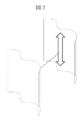
- FIG. 7 is a schematic diagram showing a cross-sectional shape of a vibration welded portion of an underfloor structural component.
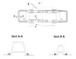
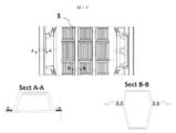
- FIG. 8 is a schematic view showing an assembling method when the vehicle frame member is an upper floor structural component.
- FIG. 9 is a schematic view showing an assembling method when the vehicle frame member is an upper floor structural component.
- FIG. 10 is a schematic diagram showing the cross-sectional shape of the vibration welded portion of the upper floor structural component.
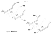
- FIG. 11 is a schematic view showing an assembling method when the vehicle skeleton member is a side sill structural component.
- FIG. 12 is a schematic diagram showing a cross-sectional shape of a vibration welded portion of a side sill structure component.
- FIG. 13 is a schematic view showing an assembling method when the vehicle skeleton member is a vehicle body superstructure part.
- FIG. 14 is a schematic view showing an assembling method when the vehicle skeleton member is a vehicle body superstructure part.
- FIG. 15 is a schematic diagram showing the cross-sectional shape of the vibration welded portion of the vehicle body superstructure part.
- FIG. 16 is a schematic diagram showing an assembling method in a case where the structural parts are integrated to form a vehicle skeleton member.
- FIG. 17 is a schematic diagram showing a cross-sectional shape of a vibration welded portion of an integrated vehicle skeleton member.
- Vehicle frame member 2 Under floor structure parts (2a, 2b, 2c, 2d parts) 3 Upper floor structure parts (3a, 3b, 3c, 3d, 3e, 3f, 3g parts) 4 Side sill structural parts (4a, 4b, 4c parts) 5 Side sill structural parts (5a, 5b, 5c parts) 6 Car body superstructure parts (pillar roof) (6a, 6b, 6c, 6d, 6e, 6f parts)
- the vehicle skeleton member of the present invention is a member that constitutes the body of an automobile. Specific examples thereof include a floor structure component, a side sill structure component, a vehicle body upper structure component including a pillar / roof rail, and the like, and a composite thereof.
- the vehicle skeleton member includes a member made of a composite material of a thermoplastic resin and a reinforcing fiber, and has a portion where these members made of the composite material are fastened.
- the ratio of the members made of the composite material in the vehicle frame member is high. Specifically, the weight ratio of the member made of the composite material in the vehicle skeleton member is 50% or more, more preferably 80% or more and 100% or less.
- Vibration welding is a method in which two members (resin parts, etc.) are brought into contact with each other under pressure, and the resin is melted and joined by frictional heat generated between the two members by periodically vibrating.
- the vibration welding machine can be used.
- the thermoplastic resin that is the matrix of the composite material is melted and fastened by vibration.
- the vehicle skeleton member according to the present invention is characterized in that the vehicle skeleton member is designed such that an axis parallel to the longitudinal direction of the vehicle body and / or the lateral direction of the vehicle body is included in a fastening surface to which vibration welding is performed.
- the vehicle skeleton member of the present invention has a portion fastened by vibration welding by arranging a fastening portion so that an axis parallel to the longitudinal direction of the vehicle body and / or the lateral direction of the vehicle body is included in the fastening surface.
- the term “parallel” does not need to be completely parallel, and a deviation of about plus or minus 10 degrees can be tolerated. Also in this case, it is preferable that the plurality of fastening surfaces are displaced at a constant angle.
- the vehicle skeleton member may have a fastening surface that does not include an axis parallel to the longitudinal direction of the vehicle body and / or the lateral direction of the vehicle body, but the fastening includes an axis parallel to the longitudinal direction of the vehicle body and / or the lateral direction of the vehicle body.
- the ratio of the surface is preferably 50 to 100% of the fastening part area.
- the ratio of the fastening surface including parallel axes is preferably 80 to 100% of the fastening part area.
- the fastening area refers to a design fastening area that is individually set according to the type of fastening method when designing the strength of fastening parts between parts or members or between parts and members. The area is different. For example, in FIGS.
- a portion indicated by an arrow in the cross-sectional view is a vibration welding portion, and a total area of these portions is a fastening area.
- the sum total of the fastening areas of all fastening parts in the vehicle frame member is defined as the total fastening area.
- the ratio of the fastening surface including the axis parallel to the vehicle longitudinal direction and / or the vehicle lateral direction is high in the vehicle skeleton member.
- 50% or more of all fastening portions include an axis parallel to the longitudinal direction of the vehicle body and / or the lateral direction of the vehicle body.
- the fastening portions include an axis parallel to the longitudinal direction of the vehicle body and / or the lateral direction of the vehicle body.
- a fastening surface that does not include an axis parallel to the longitudinal direction of the vehicle body and / or the lateral direction of the vehicle body in the vehicle skeleton member can also be fastened by vibration welding by adjusting the direction of the vibration welding apparatus or jig each time.
- the fastening surface of the composite material constituting the vehicle skeleton member is set to the front-rear direction and / or the left-right direction of the vehicle.
- a plurality of fastening surfaces of the vehicle skeleton member are in the same direction.
- the ratio of the fastening surfaces in the same direction to the total fastening area is preferably 50 to 100%, more preferably 80 to 100%.
- the definition of the fastening area is as described above.
- the fastening surface between the composite materials in the vehicle skeleton member is preferably a flat surface and / or a curved surface having an equal cross-sectional shape.
- a curved surface having an equal cross-sectional shape is a shape in which a plane having a curve is extruded in parallel. Examples of the cross-sectional shape include a circle, an ellipse, a semicircle, and a kamaboko shape.
- FIG. 1 shows the relationship between the planar fastening surface and the vibration direction, and the vibration direction can be arbitrarily selected within the surface.
- FIG. 2 shows the relationship between the fastening surface having the same cross-sectional shape and the vibration direction.
- the vibration direction is limited to the extrusion direction of the equal cross-section.
- the fastening surface is other than a flat surface and / or a curved surface having an equal cross-sectional shape, it can be appropriately fastened by a method other than vibration welding.
- it is preferable that 50% to 100% of the total fastening area of the composite material is fastening by vibration welding.
- the definition of the fastening area is as described above.
- the vehicle skeleton member may include a fastening portion that does not depend on vibration welding, but it is preferable to increase the fastening rate by vibration welding from the viewpoint of weight reduction. More preferably, 70 to 100% of the total fastening area is fastening by vibration welding. Further, with respect to the fastening surface, it is preferable that 50% or more of all fastening locations are fastening by vibration welding, and further 80% or more is fastening by vibration welding.
- a fastening method other than vibration welding in a composite material a method using an adhesive, a method of mechanical fastening with bolts and nuts, a matrix resin thermoplastic resin by heat melting and bonding using a method other than vibration, and the like are known. The method is used.
- a clearance is required to vibrate and melt the fastening surface by friction.
- a known vibration welding apparatus requires a clearance of about 2 mm in the vibration direction, a member shape that allows clearance to be provided on the roof rail is used, and a method other than vibration welding is used in combination at a portion where it is difficult to secure the clearance. It is also possible.
- the reinforcing fiber constituting the composite material various fibers according to the use of the fastening structure can be used, but glass fiber, polyester fiber, polyolefin fiber, carbon fiber, para-aramid fiber, meta-aramid fiber, boron fiber, At least one selected from the group consisting of azole fiber, alumina fiber and the like is mentioned as a preferable one, and carbon fiber excellent in specific strength and specific elasticity is particularly preferable.
- the form of the reinforcing fiber in the composite material may be a discontinuous fiber or a continuous fiber, and two or more of these may be used in combination.
- the discontinuous fiber is specifically a short fiber having a fiber length of 0.1 to less than 10 mm or a long fiber having a fiber length of 10 mm to 100 mm.
- the continuous fiber is discontinuous depending on the size and shape of the member. Therefore, a fiber having a fiber length of more than 100 mm is regarded as a continuous fiber.
- discontinuous fibers paper made using chopped strands or the like, or a two-dimensional random mat is preferable.
- a woven or knitted fabric, a unidirectionally arranged sheet-like strand, a sheet such as a multiaxial woven fabric, or a non-woven fabric is preferred.
- multiaxial woven fabrics are generally nylon yarns, polyester yarns, glass fibers, which are bundles of fiber reinforcements that are aligned in one direction and are laminated at different angles (polyaxial woven fabric base material).
- the fiber reinforced material constituting the fiber-reinforced composite material molded body may be one in which reinforcing fibers are randomly dispersed or one having a specific fiber orientation, one in which reinforcing fibers are plane-oriented or uniaxially oriented, or those A combination or a laminate thereof is preferable.
- the fiber reinforced composite material is preferably a random fiber reinforced composite material in which chopped fibers are randomly oriented in a thermoplastic resin. Furthermore, a two-dimensional random fiber reinforced composite material in which chopped fibers are two-dimensionally oriented in a thermoplastic resin is extremely excellent in moldability and has a complex shape including not only a planar shape but also a curved portion. A member can also be used. Those in which these random fiber reinforced composite materials are combined with other types of fiber reinforced composite materials or laminated materials can be suitably used for the vehicle skeleton member of the present invention.
- the fiber reinforced composite material may be a laminate or a sandwich structure having a fiber reinforced composite material layer and a resin-only layer or a fiber reinforced composite material layer in which the type of the reinforced fiber is changed.
- the core member may be a composite material and the skin member may be a resin.
- the core member may be a resin-only portion and the skin member may be a composite material.
- the weight ratio of reinforcing fiber / thermoplastic resin in the fiber-reinforced composite material is preferably 20/80 to 80/20. More preferably, it is 30/70 to 70/30.
- the thermoplastic resin include polycarbonate resin, polyolefin resin, polyester resin, acrylic resin, polylactic acid, polyamide resin, ASA resin, ABS resin, polyether ketone resin, polyether imide resin, polyphenylene ether resin, polyphenylene.
- Examples thereof include an oxide resin, a polysulfone resin, a polyethersulfone resin, a polyetherimide resin, a polyetheretherketone resin, a polyphenylene sulfide resin, a polyamideimide resin, and a mixture (resin composition) of two or more selected from these resins.
- an oxide resin a polysulfone resin, a polyethersulfone resin, a polyetherimide resin, a polyetheretherketone resin, a polyphenylene sulfide resin, a polyamideimide resin, and a mixture (resin composition) of two or more selected from these resins.
- FIG. 3 is a schematic view showing a vehicle skeleton member according to an embodiment of the present invention.
- the vehicle skeleton member 1 in this embodiment includes an under floor structural component 2, an upper floor structural component 3, left and right side sill structural components 4 and 5, and a vehicle body upper structural component 6 including pillars and roof rails. Consists of As in this embodiment, the under-floor structural component 2, the upper floor structural component 3, the side sill structural components 4 and 5, and the vehicle body upper structural component 6 may be combined to form a vehicle skeleton member. A composite of two or more structural parts may be used as the vehicle skeleton member.
- FIGS. 1 is a schematic view showing a vehicle skeleton member according to an embodiment of the present invention.
- the vehicle skeleton member 1 in this embodiment includes an under floor structural component 2, an upper floor structural component 3, left and right side sill structural components 4 and 5, and a vehicle body upper structural component 6 including pillars and roof rails. Consists of As in this embodiment, the under-floor structural component 2, the upper floor structural component 3,
- the underfloor structure component 2 can be manufactured by vibrating and welding the component 2a and the component 2b to manufacture the component 2c, and by vibrating and welding the component 2c to the lower surface of the component 2d.
- the component 2c may be manufactured by being divided into a component 2a and a component 2b, or may be integrally formed.
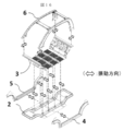
- FIGS. 8 to 9 show an assembling method when the vehicle frame member is the upper floor structural component 3.
- the parts 3a and 3b are vibration welded to produce the parts 3c
- the parts 3d and 3e are vibration welded and then vibration welded to the parts 3c
- the parts 3f are vibration welded to the parts 3c.
- the part 3g may have a structure that can be removed as a cover for storing the battery in the floor, or may be joined to the part 3c by vibration welding.
- the part 3a, the part 3b, and the part 3e may be divided and manufactured and then joined by vibration welding, or may be integrally formed in a mold.
- FIG. 10 shows the cross-sectional shape of the vibration welded portion of the upper floor structural component 3, and the arrow in the cross-sectional view is the vibration welded portion.
- FIG. 11 shows an assembling method in the case where the vehicle skeleton member is the side sill structural parts 4 and 5.
- the side sill structure parts 4 and 5 can be manufactured by vibration welding the parts 4a and 4b and the parts 5a and 5b and then vibration welding the parts 4c and 5c, respectively.
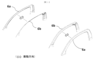
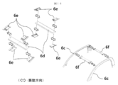
- FIGS. 13 to 14 show an assembling method when the vehicle skeleton member is the vehicle body superstructure part 6.
- the parts 6a and 6b are vibration welded to produce a pair of left and right pillars 6c.
- the component 6a and the component 6b may be manufactured separately, or may be integrally formed with a hollow body.
- the roof rail 6f is manufactured by vibration welding so that the component 6d is sandwiched between the components 6e, and the pillar 6c and the roof rail 6f are joined by vibration welding.
- the part 6d may be manufactured by dividing the part 6e, or may be integrally formed.
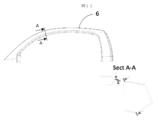
- FIG. 15 shows a cross-sectional shape of the vibration welded portion of the vehicle body upper structural component 6, and an arrow in the cross-sectional view is the vibration welded portion.
- FIG. 16 shows an assembling method in a case where the underbody structural component 2, the upper floor structural component 3, the left and right side sill structural components 4 and 5, and the vehicle body upper structural component 6 including pillars and roof rails are integrated into a vehicle body frame member.
- the vehicle body skeleton member 1 is integrated by vibration welding the under floor structural component 2 and the side sill structural components 4 and 5, and then vibration welding the upper floor structural component 3 and further vibration welding the vehicle body upper structural component 5. Is produced.
- FIG. 17 shows a cross-sectional shape of the vibration welded portion of the vehicle body skeleton member 1 integrated. An arrow portion in the cross-sectional view is the vibration welded portion.
Abstract
Description
車両骨格部材は車体の剛性を高めるための補強構造や、居住空間を設けるため、非常に複雑な形状となっているが、ロボット化されたスポット溶接技術により接合部の形状に大きな制限を必要としないため高い生産性を可能としている。
一方、近年では自動車の環境負荷を下げるために、車体重量の軽減が強く望まれるようになり、炭素繊維複合材料を車両骨格部材に適用する試みがなされている。これらの炭素繊維複合材料製車両骨格部材は、既存のスチールによる車両骨格部材よりも大幅な軽量化がなされているが、既存のスチール製車両骨格部材の複雑な形状を踏襲するため、高価な炭素繊維織物を用い、かつ生産性の低いハンドレイアップやオートクレーブ法を使って成形されている。したがって、経済性の面からその普及は極めて限定的である。最近では、RTM法(レジントランスファーモールディング法)などを用いることで生産性を改善する試みもなされているが(特許文献1参照)、マトリクスとして用いる熱硬化性樹脂の硬化反応時間が律速となり、汎用車両に適用可能な技術とは言いがたい。
また、繊維強化複合材料を車両骨格部材に適用するにあたっては、繊維強化複合材料同士の接合、および繊維強化複合材料と金属などの他材料との接合が課題となっている。繊維強化複合材料は軽量高強度な反面、ボルト締結などの局所的な荷重を作用させるのは好ましくないため、締結部の荷重を分散させるための構造が数多く提案されている。特許文献2に繊維強化複合材料の取り付け構造の例を示す。これらの構造により締結部分の応力集中を回避することは可能となるが、構造が複雑となるため生産性の改善には限界がある。
一方で繊維強化複合材料の生産性を向上するための手段として、マトリクスに熱可塑樹脂を用いた熱可塑性繊維強化複合材料が開発されている。熱可塑性繊維強化複合材料は加熱して可塑化させた後に、スタンピング成形により短タクトで形状を付与することが可能であり、スタンピング時に必要なプレス圧力がスチールのスタンピング成形よりも低いため、車両用フロア程度の大きさであれば、一体成形することが可能である。また、熱可塑性繊維強化複合材料は再加熱により軟化させることが可能なため、溶着による接合が可能であることも特徴の一つである。
図2は等断面形状の締結面と振動方向の模式図である。
図3は本発明の車両骨格部材の実施例を示す模式図である。
図4は本発明の車両骨格部材の構成を示す模式図である。
図5は車両骨格部材がアンダーフロア構造部品である場合の組立方法を示す模式図である。
図6は車両骨格部材がアンダーフロア構造部品である場合の組立方法を示す模式図である。
図7はアンダーフロア構造部品の振動溶着部分の断面形状を示す模式図である。
図8は車両骨格部材がアッパーフロア構造部品である場合の組立方法を示す模式図である。
図9は車両骨格部材がアッパーフロア構造部品である場合の組立方法を示す模式図である。
図10はアッパーフロア構造部品の振動溶着部分の断面形状を示す模式図である。
図11は車両骨格部材がサイドシル構造部品である場合の組立方法を示す模式図である。
図12はサイドシル構造部品の振動溶着部分の断面形状を示す模式図である。
図13は車両骨格部材が車体上部構造部品である場合の組立方法を示す模式図である。
図14は車両骨格部材が車体上部構造部品である場合の組立方法を示す模式図である。
図15は車体上部構造部品の振動溶着部分の断面形状を示す模式図である。
図16は各構造部品を一体化して車両骨格部材を構成する場合の組立方法を示す模式図である。
図17は一体化された車両骨格部材の振動溶着部分の断面形状を示す模式図である。
2 アンダーフロア構造部品
(2a、2b、2c、2d 部品)
3 アッパーフロア構造部品
(3a、3b、3c、3d、3e、3f、3g 部品)
4 サイドシル構造部品
(4a、4b、4c 部品)
5 サイドシル構造部品
(5a、5b、5c 部品)
6 車体上部構造部品(ピラー・ルーフ)
(6a、6b、6c、6d、6e、6f 部品)
[車両骨格部材]
本発明の車両骨格部材は、自動車の車体を構成する部材であり、具体例としてはフロア構造部品、サイドシル構造部品、ピラー・ルーフレール等を含む車体上部構造部品、およびそれらの複合体が挙げられる。車両骨格部材は、熱可塑性樹脂と強化繊維との複合材料から構成される部材を含み、これら複数の複合材料からなる部材を締結した部位を有している。車両骨格部材には、熱可塑性樹脂と強化繊維との複合材料から構成される部材以外に、金属やセラミクスといった複合材料以外の材質で構成される部材、マトリクスが熱硬化性樹脂である複合材料などを有していても良い。車体の軽量化といった観点からは、車両骨格部材における複合材料から構成される部材の比率が高いことが好ましい。具体的には車両骨格部材における複合材料から構成される部材の重量比率は50%以上、より好ましくは80%以上100%以下である。
[振動溶着、および締結面]
振動溶着とは2つの部材(樹脂部品など)を加圧により接触させた状態で、周期的に振動させることにより2部材間に発生する摩擦熱により樹脂を溶融させて接合する方法であり、公知の振動溶着機を用いて行うことができる。本発明の車両骨格部材においては、複合材料のマトリクスである熱可塑性樹脂が振動により溶融されて締結される。
本発明の車両骨格部材は、車体前後方向および/または車体左右方向に対して平行な軸が、振動溶着を施す締結面内に含まれるように車両骨格部材を設計したことを特徴とする。すなわち、本発明の車両骨格部材は締結部位を締結面内に車体前後方向および/または車体左右方向に対して平行な軸が含まれるように配置し、振動溶着により締結された部位を有することを特徴とする。ここでの平行とは、完全に平行である必要はなく、実質プラスマイナス10度程度のずれは寛容できる。この場合も、複数の締結面が一定の角度でずれていることが好ましい。
車両骨格部材中、車体前後方向および/または車体左右方向に対して平行な軸を含まない締結面があっても良いが、車体前後方向および/または車体左右方向に対して平行な軸を含む締結面の割合が締結部面積の50~100%であることが好ましい。さらには平行な軸を含む締結面の割合が締結部面積の80~100%であることが好ましい。
本発明において締結面積とは複数の部品同士や部材同士、または部品と部材の締結部の強度設計を行う時に、締結方法の種類によって個別に設定する設計上の締結面積をいい、締結部の全体の面積とは異なる。例えば、図7、図10、図12、図15、図17においては、断面図中の矢印で示す箇所が振動溶着部分であり、これらの箇所の合計面積が締結面積である。車両骨格部材において全締結部の締結面積の総和を全締結面積とする。
車両骨格部材を商業レベルで生産する場合、車両骨格部材中、車体前後方向および/または車体左右方向に対して平行な軸を含む締結面の割合が高いことが好ましい。具体的には全締結箇所の50%以上が車体前後方向および/または車体左右方向に対して平行な軸を含むことが好ましい。さらには全締結箇所の80%以上が車体前後方向および/または車体左右方向に対して平行な軸を含むことが好ましい。
車両骨格部材において車体前後方向および/または車体左右方向に対して平行な軸を含まない締結面は、振動溶着装置や治具の方向を都度調節することにより振動溶着で締結することも可能であるが、振動溶着以外の方法で適宜締結することも可能である。
生産ラインは車両の前後方向および/または左右方向に対して平行な軸に配置することが好ましいので、車両骨格部材を構成する複合材料の締結面を、車両の前後方向および/または左右方向に対して平行な軸を含むように設計することが好ましい。
車両骨格部材を商業レベルで生産する場合、車両骨格部材の複数の締結面は同一の方向にあることが生産の効率の点で好ましい。具体的には同一の方向にある締結面の全締結面積に対する割合が、好ましくは50~100%、より好ましく80~100%である。ここで締結面積の定義は上記に示したとおりである。
具体的には締結面の数について、全締結箇所の50%以上が同一の方向であること、さらには80%以上が同一の方向であることが好ましい。
振動溶着により締結するためには、車両骨格部材中の複合材料同士の締結面は、平面および/または等断面形状を有する曲面であることが好ましい。等断面形状を有する曲面とは、曲線を有する平面を平行に押し出した形状のものである。断面形状としては円、楕円、半円、かまぼこ形などが挙げられる。図1に平面状の締結面と振動方向の関係を示すが、振動方向は面内で任意に選択可である。図2に等断面形状の締結面と振動方向の関係を示すが、この場合振動方向は等断面の押し出し方向に限定されている。なお、締結面が、平面および/または等断面形状を有する曲面以外の場合は、振動溶着以外の方法で適宜締結することができる。
本発明の車両骨格部材は、複合材料の全締結面積の50%~100%が振動溶着による締結であることが好ましい。ここで締結面積の定義は上記に示したとおりである。車両骨格部材中には振動溶着によらない締結部が含まれていても良いが、軽量化という観点からは振動溶着による締結の割合を高めることが好ましい。より好ましくは全締結面積の70~100%が振動溶着による締結であることが好ましい。また締結面について、全締結箇所の50%以上が振動溶着による締結であること、さらには80%以上が振動溶着による締結であることが好ましい。
複合材料における振動溶着以外の締結方法としては接着剤を用いる方法、ボルト・ナットなどによる機械的に締結する方法、マトリクス樹脂の熱可塑性樹脂を振動以外の方法で加熱溶解させて接着させるなどの公知の方法が用いられる。
振動溶着においては、締結面を振動させて摩擦溶融させるためのクリアランスが必要である。例えば公知の振動溶着装置においては振動方向に2ミリ程度のクリアランスが必要なので、ルーフレールにクリアランスを設けられるような部材形状にするとともに、クリアランスが確保しにくい部位においては振動溶着以外の方法を併用することも可能である。
[複合材料]
複合材料を構成する強化繊維としては、締結構造の用途に応じた各種の繊維を使用できるが、ガラス繊維、ポリエステル繊維、ポリオレフィン繊維、炭素繊維、パラ系アラミド繊維、メタ系アラミド繊維、ボロン繊維、アゾール繊維、アルミナ繊維等からなる群から選択された少なくとも1種が好ましいものとして挙げられ、特に好ましくは比強度と比弾性に優れる炭素繊維である。
複合材料中の強化繊維の形態は、不連続繊維でも、連続繊維でも良く、これらのうち2種類以上を組み合わせて用いても良い。不連続繊維は、具体的には繊維長が0.1~10mm未満の短繊維もしくは、繊維長が10mm~100mmの長繊維であり、連続繊維は、もちろん部材の大きさや形状などにより不連続となるので、繊維長100mm超のものを連続繊維とする。不連続繊維の場合は、チョップドストランド等を用いて、抄紙されたペーパーや、二次元ランダムマットの形態が好ましい。連続繊維の場合は、織編物、ストランドの一方向配列シート状物及び多軸織物等のシート状、または不織布状の形態が好ましい。なお、多軸織物とは、一般に、一方向に引き揃えた繊維強化材の束をシート状にして角度を変えて積層したもの(多軸織物基材)を、ナイロン糸、ポリエステル糸、ガラス繊維糸等のステッチ糸で、この積層体を厚さ方向に貫通して、積層体の表面と裏面の間を表面方向に沿って往復しステッチした織物をいう。該繊維強化複合材料成形体を構成する繊維強化材料は、強化繊維がランダムに分散したものあるいは特定の繊維配向をしたものでもよく、強化繊維が面配向したものあるいは一軸配向したもの、あるいはそれらの組み合わせ、あるいはそれらの積層体であることが好ましい。
なかでも、繊維強化複合材料としては、熱可塑性樹脂にチョップド繊維がランダム配向しているランダム繊維強化複合材料であると好ましい。更に、熱可塑性樹脂にチョップド繊維が二次元ランダム配向している二次元ランダム繊維強化複合材料であると、極めて成形性に優れ、単なる平面形状だけではなく曲部を含めた複雑形状を有する車両骨格部材とすることもでき好ましい。これらランダム繊維強化複合材料を、他の種類の繊維強化複合材料と組み合わせたものや、積層体としたものについても、本発明の車両骨格部材に好適に用いることができる。 繊維強化複合材料は、例えば繊維強化複合材料層と樹脂のみの層あるいは強化繊維の種類を変えた繊維強化複合材料層を有する積層体やサンドイッチ構造にすることもできる。サンドイッチ構造の場合は、コア部材が複合材料であって表皮部材が樹脂であっても良く、逆にコア部材が樹脂のみの部分であって、表皮部材が複合材料であっても良い。
繊維強化複合材料における強化繊維/熱可塑性樹脂の重量比が、20/80~80/20であることが好ましい。より好ましくは30/70~70/30である。
熱可塑性樹脂として、具体的には、ポリカーボネート樹脂、ポリオレフィン系樹脂、ポリエステル樹脂、アクリル樹脂、ポリ乳酸、ポリアミド樹脂、ASA樹脂、ABS樹脂、ポリエーテルケトン樹脂、ポリエーテルイミド樹脂、ポリフェニレンエーテル樹脂、ポリフェニレンオキサイド樹脂、ポリスルホン樹脂、ポリエーテルスルホン樹脂、ポリエーテルイミド樹脂、ポリエーテルエーテルケトン樹脂、ポリフェニレンサルファイド樹脂、ポリアミドイミド樹脂およびこれらの樹脂から選ばれる2種類以上の混合物(樹脂組成物)が挙げられるが特に制限はない。
図3は本発明の実施例である車両骨格部材を示した模式図である。本実施例における車両骨格部材1は、図4に示すようにアンダーフロア構造部品2と、アッパーフロア構造部品3と、左右のサイドシル構造部品4・5と、ピラー・ルーフレールを含む車体上部構造部品6から構成される。本実施例のように、アンダーフロア構造部品2、アッパーフロア構造部品3、サイドシル構造部品4・5、車体上部構造部品6の全てを組み合わせて車両骨格部材としてもよく、それぞれの構造部品および/または2つ以上の構造部品の複合体を車両骨格部材としても良い。
図5~図6に車両骨格部材がアンダーフロア構造部品2である場合の組立方法を示す。部品2aと部品2bとを振動溶着し部品2cを製作し、部品2cを部品2dの下面に振動溶着することで、アンダーフロア構造部品2を製作することができる。ここで部品2cは部品2aと部品2bに分割して製作されても良く、一体成形されたものであっても良い。部品2cと部品2dを振動溶着する場合には、前後方向にクリアランスが必要になるともに、部品2cの立ち上がり部が振動溶着できないため、振動溶着以外の方法を併用するのが望ましい。
図7にアンダーフロア構造部品2の振動溶着部位の断面形状を示すが、断面図中の矢印箇所が振動溶着部分である。
図8~図9に車両骨格部材がアッパーフロア構造部品3である場合の組立方法を示す。部品3aと部品3bとを振動溶着し部品3cを製作し、部品3dと部品3eを振動溶着してから部品3cに振動溶着するとともに、部品3fを部品3cに振動溶着する。部品3gはフロア内にバッテリーを格納する場合のカバーとして取り外し可能な構造としてもよく、振動溶着によって部品3cに接合しても良い。ここで、部品3a、部品3b、部品3eは分割して製作したのちに振動溶着で接合してもよく、型内で一体成形しても良い。図10にアッパーフロア構造部品3の振動溶着部位の断面形状を示すが、断面図中の矢印箇所が振動溶着部分である。
図11に車両骨格部材がサイドシル構造部品4・5である場合の組立方法を示す。部品4aと部品4b、および部品5aと部品5bを振動溶着し、その後、部品4cと部品5cをそれぞれ振動溶着することでサイドシル構造部品4・5を製作可能である。図12にサイドシル構造部品4の振動溶着部位の断面形状を示すが、断面図中の矢印箇所が振動溶着部分である。
図13~図14に車両骨格部材が車体上部構造部品6である場合の組立方法を示す。部品6aと部品6bを振動溶着し、左右一対のピラー6cを製作する。ここで部品6aと部品6bは分割して製作しても良く、中空一体成形されても良い。その後、部品6eで部品6dを挟み込むように振動溶着してルーフレール6fを製作し、ピラー6cとルーフレール6fを振動溶着で接合する。ここで部品6dは部品6eは分割して製作しても良く、一体成形されてもよい。図15に車体上部構造部品6の振動溶着部位の断面形状を示すが、断面図中の矢印箇所が振動溶着部分である。
図16にアンダーフロア構造部品2、アッパーフロア構造部品3、左右のサイドシル構造部品4・5、ピラー・ルーフレールを含む車体上部構造部品6を一体化して車体骨格部材とする場合の組立方法を示す。
アンダーフロア構造部品2と、サイドシル構造部品4・5を振動溶着し、その後、アッパーフロア構造部品3を振動溶着し、さらに車体上部構造部品5を振動溶着することにより一体化された車体骨格部材1を製作する。図17に一体化された車体骨格部材1の振動溶着部位の断面形状を示すが、断面図中の矢印箇所が振動溶着部分である。
Claims (6)
- 熱可塑性樹脂と強化繊維との複合材料から構成される複数の部材を締結した部位を含み、締結面内に車体前後方向および/または車体左右方向に対して平行な軸が含まれ、振動溶着により締結された部位を有する車両骨格部材。
- 締結面が平面および/または等断面形状を有する曲面であることを特徴とする請求項1に記載の車両骨格部材。
- 車両骨格部材がフロア構造部品である請求項1~2のいずれか1項に記載の車両骨格部材。
- 車両骨格部材がサイドシル構造部品である請求項1~2のいずれか1項に記載の車両骨格部材。
- 車両骨格部材が車体上部構造部品である請求項1~2のいずれか1項に記載の車両骨格部材。
- 強化繊維が炭素繊維である請求項1~5のいずれかに記載の車両骨格部材。
Priority Applications (5)
| Application Number | Priority Date | Filing Date | Title |
|---|---|---|---|
| CN2012800077712A CN103402858A (zh) | 2011-02-03 | 2012-02-01 | 车辆框架部件 |
| EP12742424.0A EP2671780B1 (en) | 2011-02-03 | 2012-02-01 | Vehicle skeleton member |
| KR1020137020482A KR101886897B1 (ko) | 2011-02-03 | 2012-02-01 | 차량 골격 부재 |
| JP2012556006A JPWO2012105717A1 (ja) | 2011-02-03 | 2012-02-01 | 車両骨格部材 |
| US13/957,487 US9132859B2 (en) | 2011-02-03 | 2013-08-02 | Vehicle skeleton member |
Applications Claiming Priority (2)
| Application Number | Priority Date | Filing Date | Title |
|---|---|---|---|
| JP2011-021650 | 2011-02-03 | ||
| JP2011021650 | 2011-02-03 |
Related Child Applications (1)
| Application Number | Title | Priority Date | Filing Date |
|---|---|---|---|
| US13/957,487 Continuation US9132859B2 (en) | 2011-02-03 | 2013-08-02 | Vehicle skeleton member |
Publications (1)
| Publication Number | Publication Date |
|---|---|
| WO2012105717A1 true WO2012105717A1 (ja) | 2012-08-09 |
Family
ID=46602914
Family Applications (1)
| Application Number | Title | Priority Date | Filing Date |
|---|---|---|---|
| PCT/JP2012/052797 WO2012105717A1 (ja) | 2011-02-03 | 2012-02-01 | 車両骨格部材 |
Country Status (6)
| Country | Link |
|---|---|
| US (1) | US9132859B2 (ja) |
| EP (1) | EP2671780B1 (ja) |
| JP (2) | JPWO2012105717A1 (ja) |
| KR (1) | KR101886897B1 (ja) |
| CN (1) | CN103402858A (ja) |
| WO (1) | WO2012105717A1 (ja) |
Cited By (12)
| Publication number | Priority date | Publication date | Assignee | Title |
|---|---|---|---|---|
| WO2014184027A1 (de) * | 2013-05-16 | 2014-11-20 | Bayerische Motoren Werke Aktiengesellschaft | Crashstruktur für ein fahrzeug |
| WO2015141588A1 (ja) * | 2014-03-18 | 2015-09-24 | 帝人株式会社 | 中空構造体及び車両用部品 |
| JP2015168420A (ja) * | 2014-03-04 | 2015-09-28 | 現代自動車株式会社Hyundaimotor Company | 車両のアンダーフロアフレームシステム |
| DE102015110137A1 (de) | 2014-07-02 | 2016-01-07 | GM Global Technology Operations LLC (n. d. Gesetzen des Staates Delaware) | Schlagfeste Komponente für ein Fahrzeug |
| DE102015110302A1 (de) | 2014-07-02 | 2016-01-07 | GM Global Technology Operations LLC (n. d. Ges. d. Staates Delaware) | Verbesserte wellungsgestaltungen |
| DE102015120887A1 (de) | 2014-12-18 | 2016-06-23 | GM Global Technology Operations LLC (n. d. Ges. d. Staates Delaware) | Rotationsschweißen von Polymerkomponenten mit großer Oberfläche oder nicht komplementären Schweißgrenzflächen |
| JP2016169000A (ja) * | 2015-03-12 | 2016-09-23 | 現代自動車株式会社Hyundai Motor Company | 車両用ハイブリッドサイド・シル及びその製造方法並びにこれを有する車体 |
| EP3012175A4 (en) * | 2013-06-21 | 2017-03-22 | Teijin Limited | Vehicle of monocoque construction formed from thermoplastic resin members |
| DE102017100509A1 (de) | 2016-01-15 | 2017-07-20 | GM Global Technology Operations LLC | In-situ-Polymerisation von Polyamiden zur Verbundstoffteilreparatur |
| DE102017109362A1 (de) | 2016-05-02 | 2017-11-02 | GM Global Technology Operations LLC | Kosmetische Reparatur eines thermoplastischen Kohlenstofffaserkomposits |
| US10160172B2 (en) | 2014-08-06 | 2018-12-25 | GM Global Technology Operations LLC | Mechanical interlocking realized through induction heating for polymeric composite repair |
| US10611104B2 (en) | 2017-06-15 | 2020-04-07 | GM Global Technology Operations LLC | Heating elements for repair of molding defects for carbon fiber thermoplastic composites |
Families Citing this family (21)
| Publication number | Priority date | Publication date | Assignee | Title |
|---|---|---|---|---|
| WO2012033000A1 (ja) * | 2010-09-06 | 2012-03-15 | 東レ株式会社 | 乗用車車室用構造体およびその製造方法 |
| KR101886897B1 (ko) * | 2011-02-03 | 2018-08-08 | 데이진 가부시키가이샤 | 차량 골격 부재 |
| KR101764463B1 (ko) * | 2011-02-03 | 2017-08-04 | 데이진 가부시키가이샤 | 차량용 플로어 구조 |
| JP5487236B2 (ja) * | 2012-04-05 | 2014-05-07 | 本田技研工業株式会社 | 自動車の車体側部構造 |
| DE102012010768A1 (de) * | 2012-05-31 | 2013-12-05 | Decoma (Germany) Gmbh | Strukturbauteil für ein Kraftfahrzeug |
| DE102013006131A1 (de) * | 2013-04-10 | 2014-10-16 | Webasto SE | Dachrahmenbauteil eines Dachöffnungssystems eines Fahrzeugs |
| DE102013214782A1 (de) * | 2013-07-29 | 2015-01-29 | Bayerische Motoren Werke Aktiengesellschaft | Fahrzeugkarosserie mit zwei verklebten Karosseriebauteilen |
| US20150108793A1 (en) * | 2013-10-21 | 2015-04-23 | Teijin Limited | Carbon fiber cross member for automotive chassis structure |
| KR101611022B1 (ko) * | 2014-03-04 | 2016-04-11 | 현대자동차주식회사 | 차량의 어퍼바디 프레임 시스템 |
| US9187136B1 (en) * | 2014-08-01 | 2015-11-17 | Honda Motor Co., Ltd. | Structural pan for automotive body/frame |
| DE102015100968A1 (de) * | 2015-01-23 | 2016-07-28 | Dr. Ing. H.C. F. Porsche Aktiengesellschaft | Verfahren zur Herstellung einer Kraftfahrzeugkarosserie in Mischbauweise |
| DE102015103006A1 (de) * | 2015-03-03 | 2016-09-08 | Dr. Ing. H.C. F. Porsche Aktiengesellschaft | Seitenschweller für ein Kraftfahrzeug mit einer Schwellerverkleidung |
| JP6651318B2 (ja) * | 2015-09-25 | 2020-02-19 | スズキ株式会社 | 車両用フロアパネル |
| FR3042160B1 (fr) * | 2015-10-13 | 2017-10-20 | Renault Sas | Element d'habillage pour cote de caisse destine a habiller un montant de baie et au moins une partie d'un brancard |
| US9988102B2 (en) * | 2016-02-18 | 2018-06-05 | New England Wheels, Inc. | Modular vehicle |
| JP6312736B2 (ja) * | 2016-04-19 | 2018-04-18 | 本田技研工業株式会社 | 自動車の車体構造 |
| KR102588926B1 (ko) * | 2016-12-13 | 2023-10-17 | 현대자동차주식회사 | 차체 하부구조 |
| IT201600130313A1 (it) * | 2016-12-22 | 2018-06-22 | Automobili Lamborghini Spa | Struttura portante di veicolo |
| KR20220121323A (ko) * | 2021-02-25 | 2022-09-01 | 현대자동차주식회사 | 차량용 언더바디 |
| US20230054062A1 (en) * | 2021-08-18 | 2023-02-23 | GM Global Technology Operations LLC | Transparent composite for a vehicle roof |
| CN114670926B (zh) * | 2022-04-11 | 2023-08-08 | 北京汽车集团越野车有限公司 | 一种腹板式车架总成 |
Citations (12)
| Publication number | Priority date | Publication date | Assignee | Title |
|---|---|---|---|---|
| JPS61166776A (ja) * | 1985-01-18 | 1986-07-28 | Honda Motor Co Ltd | 小型車両の車体 |
| JPS6432982A (en) * | 1987-07-28 | 1989-02-02 | Mazda Motor | Resin car body structure of automobile |
| JPH04135720A (ja) * | 1990-09-27 | 1992-05-11 | Mazda Motor Corp | 繊維強化樹脂成形品の製造方法 |
| JPH06278660A (ja) * | 1993-03-30 | 1994-10-04 | Mazda Motor Corp | 自動車のキャビン構造 |
| JPH08142197A (ja) * | 1994-11-21 | 1996-06-04 | Toyota Motor Corp | 樹脂製品の製造方法 |
| JP2003118651A (ja) * | 2001-10-12 | 2003-04-23 | Kansai Paint Co Ltd | 自動車車体の製造方法 |
| JP2005225393A (ja) * | 2004-02-13 | 2005-08-25 | Calsonic Kansei Corp | 車両用クロスカービーム |
| JP2006044260A (ja) * | 2004-07-07 | 2006-02-16 | Toray Ind Inc | 一体化構造部材およびその製造方法 |
| JP2006044261A (ja) * | 2004-07-08 | 2006-02-16 | Toray Ind Inc | 繊維強化複合材料の製造方法および繊維強化複合材料ならびにそれを用いた一体化構造部材 |
| JP2006064010A (ja) | 2004-08-24 | 2006-03-09 | Toyota Motor Corp | 繊維強化樹脂取付構造 |
| JP2008068720A (ja) | 2006-09-13 | 2008-03-27 | Toyota Motor Corp | 車体パネル構造 |
| JP2008195223A (ja) * | 2007-02-13 | 2008-08-28 | Toyota Motor Corp | 車体骨格構造 |
Family Cites Families (34)
| Publication number | Priority date | Publication date | Assignee | Title |
|---|---|---|---|---|
| JPS6360743A (ja) * | 1986-09-02 | 1988-03-16 | 東レ株式会社 | 軽量複合材料 |
| JPS63232083A (ja) * | 1987-03-20 | 1988-09-28 | Honda Motor Co Ltd | 自動車のフロア部構造 |
| DE3915991A1 (de) | 1989-05-17 | 1990-11-22 | Lemfoerder Metallwaren Ag | Spurstange fuer kraftfahrzeuge |
| JPH0733987Y2 (ja) * | 1989-06-20 | 1995-08-02 | 本田技研工業株式会社 | サンドイッチ構造体からなる車両の車体構造 |
| JPH0640807U (ja) * | 1992-10-30 | 1994-05-31 | ティーディーケイ株式会社 | 変位センサ |
| JP3211589B2 (ja) * | 1994-11-09 | 2001-09-25 | トヨタ自動車株式会社 | 樹脂製品の振動溶着金型 |
| US6092862A (en) * | 1996-05-14 | 2000-07-25 | Isuzu Motors Limited | Floor structure for truck's load-carrying platform |
| US6206458B1 (en) * | 1999-09-13 | 2001-03-27 | Daimlerchrysler Corporation | Vehicle body structure |
| DE50004943D1 (de) * | 1999-10-20 | 2004-02-05 | Rcc Regional Compact Car Ag Ku | Fahrzeugzelle aus faserverstärktem thermoplastischem kunststoff |
| US6296301B1 (en) * | 1999-12-21 | 2001-10-02 | Daimlerchrysler Corporation | Motor vehicle body structure using a woven fiber |
| US6648402B2 (en) * | 2000-02-22 | 2003-11-18 | Delphi Technologies, Inc. | Structural support brace |
| US6817651B2 (en) * | 2002-05-01 | 2004-11-16 | Schlegel Corporation | Modular vehicular window seal assembly |
| US7128360B2 (en) * | 2002-12-10 | 2006-10-31 | Delphi Technologies, Inc. | Structural hybrid attachment system and method |
| EP1772356B9 (en) * | 2003-01-24 | 2012-07-18 | Club Car, LLC | Composite body for a golf car and utility vehicle |
| JP4297758B2 (ja) * | 2003-09-04 | 2009-07-15 | 株式会社アルファ | 錠装置 |
| EP1714856B1 (en) * | 2004-01-23 | 2012-03-14 | Toray Industries, Inc. | Frp panel for automobile |
| CN101824205B (zh) | 2004-02-27 | 2014-04-16 | 东丽株式会社 | 一体化成型品、纤维增强复合材料板及电气·电子设备用外壳 |
| JP2005317942A (ja) * | 2004-03-29 | 2005-11-10 | Toray Ind Inc | 電気・電子機器 |
| JP2005297417A (ja) * | 2004-04-14 | 2005-10-27 | Toray Ind Inc | 工業用構造部材およびその製造方法 |
| US8066321B2 (en) * | 2005-11-21 | 2011-11-29 | Kevin Lusk | Structural shear plate for a vehicle |
| CA2688924C (en) * | 2005-11-21 | 2012-12-04 | Faroex Ltd. | Joint for a composite vehicle body |
| JP4988230B2 (ja) * | 2006-03-30 | 2012-08-01 | 帝人テクノプロダクツ株式会社 | 繊維強化熱可塑性樹脂シートとその製造方法 |
| JP2007313778A (ja) * | 2006-05-26 | 2007-12-06 | Teijin Techno Products Ltd | 繊維強化熱可塑性樹脂複合材の接合方法 |
| JP2008143936A (ja) * | 2006-12-06 | 2008-06-26 | Toyota Motor Corp | 接着部構造 |
| JP2008143358A (ja) * | 2006-12-11 | 2008-06-26 | Toyota Motor Corp | 接着部構造 |
| JP4862913B2 (ja) * | 2009-03-31 | 2012-01-25 | 東レ株式会社 | プリプレグおよびプリフォーム |
| KR101146612B1 (ko) | 2008-07-31 | 2012-05-14 | 도레이 카부시키가이샤 | 프리프레그, 프리폼, 성형품 및 프리프레그의 제조방법 |
| DE102009005763A1 (de) * | 2009-01-23 | 2010-07-29 | Lanxess Deutschland Gmbh | Rahmenseitenteil einer Kraftfahrzeug Karosserie |
| US20120104803A1 (en) * | 2010-10-29 | 2012-05-03 | Aptera Motors, Inc. | Automotive vehicle composite body structure |
| CN103402753B (zh) * | 2011-01-28 | 2016-10-05 | 帝人株式会社 | 碳素纤维强化复合材料接合体 |
| KR101764463B1 (ko) * | 2011-02-03 | 2017-08-04 | 데이진 가부시키가이샤 | 차량용 플로어 구조 |
| KR101886897B1 (ko) * | 2011-02-03 | 2018-08-08 | 데이진 가부시키가이샤 | 차량 골격 부재 |
| CN103339023B (zh) * | 2011-02-03 | 2016-03-02 | 帝人株式会社 | 车辆骨架构件 |
| JP5889120B2 (ja) * | 2012-06-15 | 2016-03-22 | 三菱電機株式会社 | 放送番組予約録画装置 |
-
2012
- 2012-02-01 KR KR1020137020482A patent/KR101886897B1/ko active IP Right Grant
- 2012-02-01 WO PCT/JP2012/052797 patent/WO2012105717A1/ja active Application Filing
- 2012-02-01 CN CN2012800077712A patent/CN103402858A/zh active Pending
- 2012-02-01 EP EP12742424.0A patent/EP2671780B1/en not_active Not-in-force
- 2012-02-01 JP JP2012556006A patent/JPWO2012105717A1/ja active Pending
-
2013
- 2013-08-02 US US13/957,487 patent/US9132859B2/en not_active Expired - Fee Related
-
2015
- 2015-12-14 JP JP2015242979A patent/JP6286411B2/ja not_active Expired - Fee Related
Patent Citations (12)
| Publication number | Priority date | Publication date | Assignee | Title |
|---|---|---|---|---|
| JPS61166776A (ja) * | 1985-01-18 | 1986-07-28 | Honda Motor Co Ltd | 小型車両の車体 |
| JPS6432982A (en) * | 1987-07-28 | 1989-02-02 | Mazda Motor | Resin car body structure of automobile |
| JPH04135720A (ja) * | 1990-09-27 | 1992-05-11 | Mazda Motor Corp | 繊維強化樹脂成形品の製造方法 |
| JPH06278660A (ja) * | 1993-03-30 | 1994-10-04 | Mazda Motor Corp | 自動車のキャビン構造 |
| JPH08142197A (ja) * | 1994-11-21 | 1996-06-04 | Toyota Motor Corp | 樹脂製品の製造方法 |
| JP2003118651A (ja) * | 2001-10-12 | 2003-04-23 | Kansai Paint Co Ltd | 自動車車体の製造方法 |
| JP2005225393A (ja) * | 2004-02-13 | 2005-08-25 | Calsonic Kansei Corp | 車両用クロスカービーム |
| JP2006044260A (ja) * | 2004-07-07 | 2006-02-16 | Toray Ind Inc | 一体化構造部材およびその製造方法 |
| JP2006044261A (ja) * | 2004-07-08 | 2006-02-16 | Toray Ind Inc | 繊維強化複合材料の製造方法および繊維強化複合材料ならびにそれを用いた一体化構造部材 |
| JP2006064010A (ja) | 2004-08-24 | 2006-03-09 | Toyota Motor Corp | 繊維強化樹脂取付構造 |
| JP2008068720A (ja) | 2006-09-13 | 2008-03-27 | Toyota Motor Corp | 車体パネル構造 |
| JP2008195223A (ja) * | 2007-02-13 | 2008-08-28 | Toyota Motor Corp | 車体骨格構造 |
Non-Patent Citations (1)
| Title |
|---|
| See also references of EP2671780A4 |
Cited By (25)
| Publication number | Priority date | Publication date | Assignee | Title |
|---|---|---|---|---|
| CN105228881A (zh) * | 2013-05-16 | 2016-01-06 | 宝马股份公司 | 用于车辆的碰撞结构 |
| WO2014184027A1 (de) * | 2013-05-16 | 2014-11-20 | Bayerische Motoren Werke Aktiengesellschaft | Crashstruktur für ein fahrzeug |
| EP3012175A4 (en) * | 2013-06-21 | 2017-03-22 | Teijin Limited | Vehicle of monocoque construction formed from thermoplastic resin members |
| US9802650B2 (en) | 2013-06-21 | 2017-10-31 | Teijin Limited | Vehicle of monocoque construction formed from thermoplastic resin members |
| JP2015168420A (ja) * | 2014-03-04 | 2015-09-28 | 現代自動車株式会社Hyundaimotor Company | 車両のアンダーフロアフレームシステム |
| WO2015141588A1 (ja) * | 2014-03-18 | 2015-09-24 | 帝人株式会社 | 中空構造体及び車両用部品 |
| US9783244B2 (en) | 2014-03-18 | 2017-10-10 | Teijin Limited | Hollow structure body and vehicular component |
| JP5855802B1 (ja) * | 2014-03-18 | 2016-02-09 | 帝人株式会社 | 中空構造体及び車両用部品 |
| DE102015110137A1 (de) | 2014-07-02 | 2016-01-07 | GM Global Technology Operations LLC (n. d. Gesetzen des Staates Delaware) | Schlagfeste Komponente für ein Fahrzeug |
| US9592853B2 (en) | 2014-07-02 | 2017-03-14 | GM Global Technology Operations LLC | Corrugation designs |
| US9650003B2 (en) | 2014-07-02 | 2017-05-16 | GM Global Technology Operations LLC | Impact resistant component for a vehicle |
| DE102015110302A1 (de) | 2014-07-02 | 2016-01-07 | GM Global Technology Operations LLC (n. d. Ges. d. Staates Delaware) | Verbesserte wellungsgestaltungen |
| DE102015110302B4 (de) | 2014-07-02 | 2022-08-18 | GM Global Technology Operations LLC (n. d. Ges. d. Staates Delaware) | Schlagfeste Komponente für ein Fahrzeug |
| US10293770B2 (en) | 2014-07-02 | 2019-05-21 | GM Global Technology Operations LLC | Impact resistant component for a vehicle |
| US10160172B2 (en) | 2014-08-06 | 2018-12-25 | GM Global Technology Operations LLC | Mechanical interlocking realized through induction heating for polymeric composite repair |
| DE102015120887A1 (de) | 2014-12-18 | 2016-06-23 | GM Global Technology Operations LLC (n. d. Ges. d. Staates Delaware) | Rotationsschweißen von Polymerkomponenten mit großer Oberfläche oder nicht komplementären Schweißgrenzflächen |
| DE102015120887B4 (de) | 2014-12-18 | 2021-08-12 | GM Global Technology Operations LLC (n. d. Ges. d. Staates Delaware) | Reibschweißanordnung und Verfahren zum Reibschweißen |
| JP2016169000A (ja) * | 2015-03-12 | 2016-09-23 | 現代自動車株式会社Hyundai Motor Company | 車両用ハイブリッドサイド・シル及びその製造方法並びにこれを有する車体 |
| DE102017100509A1 (de) | 2016-01-15 | 2017-07-20 | GM Global Technology Operations LLC | In-situ-Polymerisation von Polyamiden zur Verbundstoffteilreparatur |
| US10695993B2 (en) | 2016-01-15 | 2020-06-30 | GM Global Technology Operations LLC | In-situ polymerization of polyamides for composite part repair |
| DE102017100509B4 (de) | 2016-01-15 | 2024-01-18 | GM Global Technology Operations LLC | In-situ-Polymerisation von Caprolactam zur Verbundstoffteilreparatur |
| US10589477B2 (en) | 2016-05-02 | 2020-03-17 | GM Global Technology Operations LLC | Cosmetic repair of a thermoplastic carbon fiber composite |
| DE102017109362A1 (de) | 2016-05-02 | 2017-11-02 | GM Global Technology Operations LLC | Kosmetische Reparatur eines thermoplastischen Kohlenstofffaserkomposits |
| DE102017109362B4 (de) | 2016-05-02 | 2023-08-10 | GM Global Technology Operations LLC | Kosmetische Reparatur eines thermoplastischen Kohlenstofffaserkomposits |
| US10611104B2 (en) | 2017-06-15 | 2020-04-07 | GM Global Technology Operations LLC | Heating elements for repair of molding defects for carbon fiber thermoplastic composites |
Also Published As
| Publication number | Publication date |
|---|---|
| JPWO2012105717A1 (ja) | 2014-07-03 |
| EP2671780A1 (en) | 2013-12-11 |
| KR101886897B1 (ko) | 2018-08-08 |
| JP2016055867A (ja) | 2016-04-21 |
| CN103402858A (zh) | 2013-11-20 |
| US9132859B2 (en) | 2015-09-15 |
| US20130313863A1 (en) | 2013-11-28 |
| EP2671780B1 (en) | 2015-09-09 |
| EP2671780A4 (en) | 2014-04-09 |
| KR20140012973A (ko) | 2014-02-04 |
| JP6286411B2 (ja) | 2018-02-28 |
Similar Documents
| Publication | Publication Date | Title |
|---|---|---|
| JP6286411B2 (ja) | 車両骨格部材の製造方法 | |
| WO2012105716A1 (ja) | 車両骨格部材 | |
| JP5581404B2 (ja) | 車両用フロア構造 | |
| KR101613687B1 (ko) | 자동차용 시트 백 프레임 및 그 제조방법 | |
| JP7020333B2 (ja) | 車両構成部材及びその製造方法 | |
| EP2572931B1 (en) | Vehicle seat | |
| JP5548192B2 (ja) | 強化補強材を作製する方法 | |
| WO2012102315A1 (ja) | 炭素繊維強化複合材料の接合体 | |
| JP2015160524A (ja) | 自動車の車体構造 | |
| JP5771019B2 (ja) | 車両用シートバックフレーム構造 | |
| JP2020124837A (ja) | 繊維強化樹脂構造体の縁部構造 | |
| JP5771020B2 (ja) | 車両用シートバックフレーム構造 | |
| JP6313973B2 (ja) | 積層構造体およびその製造方法 | |
| KR101262939B1 (ko) | 하이브리드 복합소재의 용접성 개선을 위한 방법 및 그 방법에 의해 제조된 하이브리드 복합소재 | |
| JP2019171619A (ja) | 補強金属部材及びその製造方法 | |
| JP2021017127A (ja) | 移動体の構造体、および移動体の構造体の製造方法 | |
| JP2014100836A (ja) | 熱可塑性樹脂複合部材の製造方法と製造装置 |
Legal Events
| Date | Code | Title | Description |
|---|---|---|---|
| 121 | Ep: the epo has been informed by wipo that ep was designated in this application |
Ref document number: 12742424 Country of ref document: EP Kind code of ref document: A1 |
|
| DPE2 | Request for preliminary examination filed before expiration of 19th month from priority date (pct application filed from 20040101) | ||
| ENP | Entry into the national phase |
Ref document number: 2012556006 Country of ref document: JP Kind code of ref document: A |
|
| ENP | Entry into the national phase |
Ref document number: 20137020482 Country of ref document: KR Kind code of ref document: A |
|
| NENP | Non-entry into the national phase |
Ref country code: DE |
|
| WWE | Wipo information: entry into national phase |
Ref document number: 2012742424 Country of ref document: EP |