EP2671780B1 - Vehicle skeleton member - Google Patents
Vehicle skeleton member Download PDFInfo
- Publication number
- EP2671780B1 EP2671780B1 EP12742424.0A EP12742424A EP2671780B1 EP 2671780 B1 EP2671780 B1 EP 2671780B1 EP 12742424 A EP12742424 A EP 12742424A EP 2671780 B1 EP2671780 B1 EP 2671780B1
- Authority
- EP
- European Patent Office
- Prior art keywords
- skeleton member
- vehicle skeleton
- vehicle
- vibration
- joining
- Prior art date
- Legal status (The legal status is an assumption and is not a legal conclusion. Google has not performed a legal analysis and makes no representation as to the accuracy of the status listed.)
- Not-in-force
Links
- 238000005304 joining Methods 0.000 claims description 69
- 238000003466 welding Methods 0.000 claims description 44
- 239000000463 material Substances 0.000 claims description 28
- 239000003733 fiber-reinforced composite Substances 0.000 claims description 21
- 239000012783 reinforcing fiber Substances 0.000 claims description 18
- 229920005992 thermoplastic resin Polymers 0.000 claims description 18
- 238000004519 manufacturing process Methods 0.000 claims description 14
- 229920000049 Carbon (fiber) Polymers 0.000 claims description 7
- 239000004917 carbon fiber Substances 0.000 claims description 7
- VNWKTOKETHGBQD-UHFFFAOYSA-N methane Chemical group C VNWKTOKETHGBQD-UHFFFAOYSA-N 0.000 claims description 6
- 239000011208 reinforced composite material Substances 0.000 claims 1
- 238000000034 method Methods 0.000 description 27
- 239000002131 composite material Substances 0.000 description 26
- 239000000835 fiber Substances 0.000 description 22
- 229920005989 resin Polymers 0.000 description 20
- 239000011347 resin Substances 0.000 description 20
- 239000011159 matrix material Substances 0.000 description 5
- 239000002759 woven fabric Substances 0.000 description 5
- 239000002184 metal Substances 0.000 description 4
- 238000002844 melting Methods 0.000 description 3
- 230000008018 melting Effects 0.000 description 3
- 229920001169 thermoplastic Polymers 0.000 description 3
- 239000004416 thermosoftening plastic Substances 0.000 description 3
- 239000004697 Polyetherimide Substances 0.000 description 2
- KAESVJOAVNADME-UHFFFAOYSA-N Pyrrole Chemical compound C=1C=CNC=1 KAESVJOAVNADME-UHFFFAOYSA-N 0.000 description 2
- 229910000831 Steel Inorganic materials 0.000 description 2
- 239000000853 adhesive Substances 0.000 description 2
- 229920003235 aromatic polyamide Polymers 0.000 description 2
- 238000005516 engineering process Methods 0.000 description 2
- 239000003365 glass fiber Substances 0.000 description 2
- 238000010438 heat treatment Methods 0.000 description 2
- 238000000465 moulding Methods 0.000 description 2
- 229920000728 polyester Polymers 0.000 description 2
- 229920001601 polyetherimide Polymers 0.000 description 2
- 238000007493 shaping process Methods 0.000 description 2
- 239000010959 steel Substances 0.000 description 2
- 229920001187 thermosetting polymer Polymers 0.000 description 2
- 229920000178 Acrylic resin Polymers 0.000 description 1
- 239000004925 Acrylic resin Substances 0.000 description 1
- ZOXJGFHDIHLPTG-UHFFFAOYSA-N Boron Chemical compound [B] ZOXJGFHDIHLPTG-UHFFFAOYSA-N 0.000 description 1
- 239000004677 Nylon Substances 0.000 description 1
- 239000004696 Poly ether ether ketone Substances 0.000 description 1
- 239000004962 Polyamide-imide Substances 0.000 description 1
- 239000004695 Polyether sulfone Substances 0.000 description 1
- 239000004721 Polyphenylene oxide Substances 0.000 description 1
- 239000004734 Polyphenylene sulfide Substances 0.000 description 1
- 229920002877 acrylic styrene acrylonitrile Polymers 0.000 description 1
- 229920000122 acrylonitrile butadiene styrene Polymers 0.000 description 1
- 230000001070 adhesive effect Effects 0.000 description 1
- PNEYBMLMFCGWSK-UHFFFAOYSA-N aluminium oxide Inorganic materials [O-2].[O-2].[O-2].[Al+3].[Al+3] PNEYBMLMFCGWSK-UHFFFAOYSA-N 0.000 description 1
- 238000011074 autoclave method Methods 0.000 description 1
- 230000037396 body weight Effects 0.000 description 1
- 229910052796 boron Inorganic materials 0.000 description 1
- QHIWVLPBUQWDMQ-UHFFFAOYSA-N butyl prop-2-enoate;methyl 2-methylprop-2-enoate;prop-2-enoic acid Chemical compound OC(=O)C=C.COC(=O)C(C)=C.CCCCOC(=O)C=C QHIWVLPBUQWDMQ-UHFFFAOYSA-N 0.000 description 1
- 239000000919 ceramic Substances 0.000 description 1
- 230000003247 decreasing effect Effects 0.000 description 1
- 230000000694 effects Effects 0.000 description 1
- 230000007613 environmental effect Effects 0.000 description 1
- 238000001125 extrusion Methods 0.000 description 1
- 239000004744 fabric Substances 0.000 description 1
- 238000009787 hand lay-up Methods 0.000 description 1
- 239000000203 mixture Substances 0.000 description 1
- 229920001778 nylon Polymers 0.000 description 1
- 229920001643 poly(ether ketone) Polymers 0.000 description 1
- 229920000747 poly(lactic acid) Polymers 0.000 description 1
- 229920002492 poly(sulfone) Polymers 0.000 description 1
- 229920006122 polyamide resin Polymers 0.000 description 1
- 229920002312 polyamide-imide Polymers 0.000 description 1
- 229920005668 polycarbonate resin Polymers 0.000 description 1
- 239000004431 polycarbonate resin Substances 0.000 description 1
- 229920001225 polyester resin Polymers 0.000 description 1
- 239000004645 polyester resin Substances 0.000 description 1
- 229920006393 polyether sulfone Polymers 0.000 description 1
- 229920002530 polyetherether ketone Polymers 0.000 description 1
- 239000004626 polylactic acid Substances 0.000 description 1
- 229920000098 polyolefin Polymers 0.000 description 1
- 229920005672 polyolefin resin Polymers 0.000 description 1
- 229920001955 polyphenylene ether Polymers 0.000 description 1
- 229920006380 polyphenylene oxide Polymers 0.000 description 1
- 229920000069 polyphenylene sulfide Polymers 0.000 description 1
- 238000003825 pressing Methods 0.000 description 1
- 230000035484 reaction time Effects 0.000 description 1
- 230000003014 reinforcing effect Effects 0.000 description 1
- 239000011342 resin composition Substances 0.000 description 1
- 230000000630 rising effect Effects 0.000 description 1
- 238000001721 transfer moulding Methods 0.000 description 1
Images


Classifications
-
- B—PERFORMING OPERATIONS; TRANSPORTING
- B62—LAND VEHICLES FOR TRAVELLING OTHERWISE THAN ON RAILS
- B62D—MOTOR VEHICLES; TRAILERS
- B62D25/00—Superstructure or monocoque structure sub-units; Parts or details thereof not otherwise provided for
-
- B—PERFORMING OPERATIONS; TRANSPORTING
- B62—LAND VEHICLES FOR TRAVELLING OTHERWISE THAN ON RAILS
- B62D—MOTOR VEHICLES; TRAILERS
- B62D29/00—Superstructures, understructures, or sub-units thereof, characterised by the material thereof
- B62D29/04—Superstructures, understructures, or sub-units thereof, characterised by the material thereof predominantly of synthetic material
-
- B—PERFORMING OPERATIONS; TRANSPORTING
- B29—WORKING OF PLASTICS; WORKING OF SUBSTANCES IN A PLASTIC STATE IN GENERAL
- B29C—SHAPING OR JOINING OF PLASTICS; SHAPING OF MATERIAL IN A PLASTIC STATE, NOT OTHERWISE PROVIDED FOR; AFTER-TREATMENT OF THE SHAPED PRODUCTS, e.g. REPAIRING
- B29C65/00—Joining or sealing of preformed parts, e.g. welding of plastics materials; Apparatus therefor
- B29C65/02—Joining or sealing of preformed parts, e.g. welding of plastics materials; Apparatus therefor by heating, with or without pressure
- B29C65/06—Joining or sealing of preformed parts, e.g. welding of plastics materials; Apparatus therefor by heating, with or without pressure using friction, e.g. spin welding
- B29C65/0609—Joining or sealing of preformed parts, e.g. welding of plastics materials; Apparatus therefor by heating, with or without pressure using friction, e.g. spin welding characterised by the movement of the parts to be joined
- B29C65/0618—Linear
-
- B—PERFORMING OPERATIONS; TRANSPORTING
- B29—WORKING OF PLASTICS; WORKING OF SUBSTANCES IN A PLASTIC STATE IN GENERAL
- B29C—SHAPING OR JOINING OF PLASTICS; SHAPING OF MATERIAL IN A PLASTIC STATE, NOT OTHERWISE PROVIDED FOR; AFTER-TREATMENT OF THE SHAPED PRODUCTS, e.g. REPAIRING
- B29C66/00—General aspects of processes or apparatus for joining preformed parts
- B29C66/01—General aspects dealing with the joint area or with the area to be joined
- B29C66/05—Particular design of joint configurations
- B29C66/10—Particular design of joint configurations particular design of the joint cross-sections
- B29C66/11—Joint cross-sections comprising a single joint-segment, i.e. one of the parts to be joined comprising a single joint-segment in the joint cross-section
- B29C66/112—Single lapped joints
-
- B—PERFORMING OPERATIONS; TRANSPORTING
- B29—WORKING OF PLASTICS; WORKING OF SUBSTANCES IN A PLASTIC STATE IN GENERAL
- B29C—SHAPING OR JOINING OF PLASTICS; SHAPING OF MATERIAL IN A PLASTIC STATE, NOT OTHERWISE PROVIDED FOR; AFTER-TREATMENT OF THE SHAPED PRODUCTS, e.g. REPAIRING
- B29C66/00—General aspects of processes or apparatus for joining preformed parts
- B29C66/01—General aspects dealing with the joint area or with the area to be joined
- B29C66/05—Particular design of joint configurations
- B29C66/10—Particular design of joint configurations particular design of the joint cross-sections
- B29C66/13—Single flanged joints; Fin-type joints; Single hem joints; Edge joints; Interpenetrating fingered joints; Other specific particular designs of joint cross-sections not provided for in groups B29C66/11 - B29C66/12
- B29C66/131—Single flanged joints, i.e. one of the parts to be joined being rigid and flanged in the joint area
- B29C66/1312—Single flange to flange joints, the parts to be joined being rigid
-
- B—PERFORMING OPERATIONS; TRANSPORTING
- B29—WORKING OF PLASTICS; WORKING OF SUBSTANCES IN A PLASTIC STATE IN GENERAL
- B29C—SHAPING OR JOINING OF PLASTICS; SHAPING OF MATERIAL IN A PLASTIC STATE, NOT OTHERWISE PROVIDED FOR; AFTER-TREATMENT OF THE SHAPED PRODUCTS, e.g. REPAIRING
- B29C66/00—General aspects of processes or apparatus for joining preformed parts
- B29C66/50—General aspects of joining tubular articles; General aspects of joining long products, i.e. bars or profiled elements; General aspects of joining single elements to tubular articles, hollow articles or bars; General aspects of joining several hollow-preforms to form hollow or tubular articles
- B29C66/51—Joining tubular articles, profiled elements or bars; Joining single elements to tubular articles, hollow articles or bars; Joining several hollow-preforms to form hollow or tubular articles
- B29C66/52—Joining tubular articles, bars or profiled elements
- B29C66/524—Joining profiled elements
-
- B—PERFORMING OPERATIONS; TRANSPORTING
- B29—WORKING OF PLASTICS; WORKING OF SUBSTANCES IN A PLASTIC STATE IN GENERAL
- B29C—SHAPING OR JOINING OF PLASTICS; SHAPING OF MATERIAL IN A PLASTIC STATE, NOT OTHERWISE PROVIDED FOR; AFTER-TREATMENT OF THE SHAPED PRODUCTS, e.g. REPAIRING
- B29C66/00—General aspects of processes or apparatus for joining preformed parts
- B29C66/50—General aspects of joining tubular articles; General aspects of joining long products, i.e. bars or profiled elements; General aspects of joining single elements to tubular articles, hollow articles or bars; General aspects of joining several hollow-preforms to form hollow or tubular articles
- B29C66/51—Joining tubular articles, profiled elements or bars; Joining single elements to tubular articles, hollow articles or bars; Joining several hollow-preforms to form hollow or tubular articles
- B29C66/53—Joining single elements to tubular articles, hollow articles or bars
- B29C66/534—Joining single elements to open ends of tubular or hollow articles or to the ends of bars
-
- B—PERFORMING OPERATIONS; TRANSPORTING
- B29—WORKING OF PLASTICS; WORKING OF SUBSTANCES IN A PLASTIC STATE IN GENERAL
- B29C—SHAPING OR JOINING OF PLASTICS; SHAPING OF MATERIAL IN A PLASTIC STATE, NOT OTHERWISE PROVIDED FOR; AFTER-TREATMENT OF THE SHAPED PRODUCTS, e.g. REPAIRING
- B29C66/00—General aspects of processes or apparatus for joining preformed parts
- B29C66/50—General aspects of joining tubular articles; General aspects of joining long products, i.e. bars or profiled elements; General aspects of joining single elements to tubular articles, hollow articles or bars; General aspects of joining several hollow-preforms to form hollow or tubular articles
- B29C66/51—Joining tubular articles, profiled elements or bars; Joining single elements to tubular articles, hollow articles or bars; Joining several hollow-preforms to form hollow or tubular articles
- B29C66/54—Joining several hollow-preforms, e.g. half-shells, to form hollow articles, e.g. for making balls, containers; Joining several hollow-preforms, e.g. half-cylinders, to form tubular articles
- B29C66/541—Joining several hollow-preforms, e.g. half-shells, to form hollow articles, e.g. for making balls, containers; Joining several hollow-preforms, e.g. half-cylinders, to form tubular articles a substantially flat extra element being placed between and clamped by the joined hollow-preforms
- B29C66/5414—Joining several hollow-preforms, e.g. half-shells, to form hollow articles, e.g. for making balls, containers; Joining several hollow-preforms, e.g. half-cylinders, to form tubular articles a substantially flat extra element being placed between and clamped by the joined hollow-preforms said substantially flat extra element being rigid, e.g. a plate
-
- B—PERFORMING OPERATIONS; TRANSPORTING
- B29—WORKING OF PLASTICS; WORKING OF SUBSTANCES IN A PLASTIC STATE IN GENERAL
- B29C—SHAPING OR JOINING OF PLASTICS; SHAPING OF MATERIAL IN A PLASTIC STATE, NOT OTHERWISE PROVIDED FOR; AFTER-TREATMENT OF THE SHAPED PRODUCTS, e.g. REPAIRING
- B29C66/00—General aspects of processes or apparatus for joining preformed parts
- B29C66/50—General aspects of joining tubular articles; General aspects of joining long products, i.e. bars or profiled elements; General aspects of joining single elements to tubular articles, hollow articles or bars; General aspects of joining several hollow-preforms to form hollow or tubular articles
- B29C66/51—Joining tubular articles, profiled elements or bars; Joining single elements to tubular articles, hollow articles or bars; Joining several hollow-preforms to form hollow or tubular articles
- B29C66/54—Joining several hollow-preforms, e.g. half-shells, to form hollow articles, e.g. for making balls, containers; Joining several hollow-preforms, e.g. half-cylinders, to form tubular articles
- B29C66/543—Joining several hollow-preforms, e.g. half-shells, to form hollow articles, e.g. for making balls, containers; Joining several hollow-preforms, e.g. half-cylinders, to form tubular articles joining more than two hollow-preforms to form said hollow articles
-
- B—PERFORMING OPERATIONS; TRANSPORTING
- B29—WORKING OF PLASTICS; WORKING OF SUBSTANCES IN A PLASTIC STATE IN GENERAL
- B29C—SHAPING OR JOINING OF PLASTICS; SHAPING OF MATERIAL IN A PLASTIC STATE, NOT OTHERWISE PROVIDED FOR; AFTER-TREATMENT OF THE SHAPED PRODUCTS, e.g. REPAIRING
- B29C66/00—General aspects of processes or apparatus for joining preformed parts
- B29C66/50—General aspects of joining tubular articles; General aspects of joining long products, i.e. bars or profiled elements; General aspects of joining single elements to tubular articles, hollow articles or bars; General aspects of joining several hollow-preforms to form hollow or tubular articles
- B29C66/51—Joining tubular articles, profiled elements or bars; Joining single elements to tubular articles, hollow articles or bars; Joining several hollow-preforms to form hollow or tubular articles
- B29C66/54—Joining several hollow-preforms, e.g. half-shells, to form hollow articles, e.g. for making balls, containers; Joining several hollow-preforms, e.g. half-cylinders, to form tubular articles
- B29C66/545—Joining several hollow-preforms, e.g. half-shells, to form hollow articles, e.g. for making balls, containers; Joining several hollow-preforms, e.g. half-cylinders, to form tubular articles one hollow-preform being placed inside the other
-
- B—PERFORMING OPERATIONS; TRANSPORTING
- B29—WORKING OF PLASTICS; WORKING OF SUBSTANCES IN A PLASTIC STATE IN GENERAL
- B29C—SHAPING OR JOINING OF PLASTICS; SHAPING OF MATERIAL IN A PLASTIC STATE, NOT OTHERWISE PROVIDED FOR; AFTER-TREATMENT OF THE SHAPED PRODUCTS, e.g. REPAIRING
- B29C66/00—General aspects of processes or apparatus for joining preformed parts
- B29C66/70—General aspects of processes or apparatus for joining preformed parts characterised by the composition, physical properties or the structure of the material of the parts to be joined; Joining with non-plastics material
- B29C66/72—General aspects of processes or apparatus for joining preformed parts characterised by the composition, physical properties or the structure of the material of the parts to be joined; Joining with non-plastics material characterised by the structure of the material of the parts to be joined
- B29C66/721—Fibre-reinforced materials
- B29C66/7212—Fibre-reinforced materials characterised by the composition of the fibres
-
- B—PERFORMING OPERATIONS; TRANSPORTING
- B29—WORKING OF PLASTICS; WORKING OF SUBSTANCES IN A PLASTIC STATE IN GENERAL
- B29C—SHAPING OR JOINING OF PLASTICS; SHAPING OF MATERIAL IN A PLASTIC STATE, NOT OTHERWISE PROVIDED FOR; AFTER-TREATMENT OF THE SHAPED PRODUCTS, e.g. REPAIRING
- B29C66/00—General aspects of processes or apparatus for joining preformed parts
- B29C66/70—General aspects of processes or apparatus for joining preformed parts characterised by the composition, physical properties or the structure of the material of the parts to be joined; Joining with non-plastics material
- B29C66/73—General aspects of processes or apparatus for joining preformed parts characterised by the composition, physical properties or the structure of the material of the parts to be joined; Joining with non-plastics material characterised by the intensive physical properties of the material of the parts to be joined, by the optical properties of the material of the parts to be joined, by the extensive physical properties of the parts to be joined, by the state of the material of the parts to be joined or by the material of the parts to be joined being a thermoplastic or a thermoset
- B29C66/739—General aspects of processes or apparatus for joining preformed parts characterised by the composition, physical properties or the structure of the material of the parts to be joined; Joining with non-plastics material characterised by the intensive physical properties of the material of the parts to be joined, by the optical properties of the material of the parts to be joined, by the extensive physical properties of the parts to be joined, by the state of the material of the parts to be joined or by the material of the parts to be joined being a thermoplastic or a thermoset characterised by the material of the parts to be joined being a thermoplastic or a thermoset
- B29C66/7392—General aspects of processes or apparatus for joining preformed parts characterised by the composition, physical properties or the structure of the material of the parts to be joined; Joining with non-plastics material characterised by the intensive physical properties of the material of the parts to be joined, by the optical properties of the material of the parts to be joined, by the extensive physical properties of the parts to be joined, by the state of the material of the parts to be joined or by the material of the parts to be joined being a thermoplastic or a thermoset characterised by the material of the parts to be joined being a thermoplastic or a thermoset characterised by the material of at least one of the parts being a thermoplastic
- B29C66/73921—General aspects of processes or apparatus for joining preformed parts characterised by the composition, physical properties or the structure of the material of the parts to be joined; Joining with non-plastics material characterised by the intensive physical properties of the material of the parts to be joined, by the optical properties of the material of the parts to be joined, by the extensive physical properties of the parts to be joined, by the state of the material of the parts to be joined or by the material of the parts to be joined being a thermoplastic or a thermoset characterised by the material of the parts to be joined being a thermoplastic or a thermoset characterised by the material of at least one of the parts being a thermoplastic characterised by the materials of both parts being thermoplastics
-
- B—PERFORMING OPERATIONS; TRANSPORTING
- B62—LAND VEHICLES FOR TRAVELLING OTHERWISE THAN ON RAILS
- B62D—MOTOR VEHICLES; TRAILERS
- B62D25/00—Superstructure or monocoque structure sub-units; Parts or details thereof not otherwise provided for
- B62D25/02—Side panels
- B62D25/025—Side sills thereof
-
- B—PERFORMING OPERATIONS; TRANSPORTING
- B62—LAND VEHICLES FOR TRAVELLING OTHERWISE THAN ON RAILS
- B62D—MOTOR VEHICLES; TRAILERS
- B62D25/00—Superstructure or monocoque structure sub-units; Parts or details thereof not otherwise provided for
- B62D25/04—Door pillars ; windshield pillars
-
- B—PERFORMING OPERATIONS; TRANSPORTING
- B62—LAND VEHICLES FOR TRAVELLING OTHERWISE THAN ON RAILS
- B62D—MOTOR VEHICLES; TRAILERS
- B62D25/00—Superstructure or monocoque structure sub-units; Parts or details thereof not otherwise provided for
- B62D25/06—Fixed roofs
-
- B—PERFORMING OPERATIONS; TRANSPORTING
- B62—LAND VEHICLES FOR TRAVELLING OTHERWISE THAN ON RAILS
- B62D—MOTOR VEHICLES; TRAILERS
- B62D25/00—Superstructure or monocoque structure sub-units; Parts or details thereof not otherwise provided for
- B62D25/20—Floors or bottom sub-units
-
- B—PERFORMING OPERATIONS; TRANSPORTING
- B62—LAND VEHICLES FOR TRAVELLING OTHERWISE THAN ON RAILS
- B62D—MOTOR VEHICLES; TRAILERS
- B62D25/00—Superstructure or monocoque structure sub-units; Parts or details thereof not otherwise provided for
- B62D25/20—Floors or bottom sub-units
- B62D25/2009—Floors or bottom sub-units in connection with other superstructure subunits
- B62D25/2036—Floors or bottom sub-units in connection with other superstructure subunits the subunits being side panels, sills or pillars
-
- B—PERFORMING OPERATIONS; TRANSPORTING
- B62—LAND VEHICLES FOR TRAVELLING OTHERWISE THAN ON RAILS
- B62D—MOTOR VEHICLES; TRAILERS
- B62D29/00—Superstructures, understructures, or sub-units thereof, characterised by the material thereof
- B62D29/04—Superstructures, understructures, or sub-units thereof, characterised by the material thereof predominantly of synthetic material
- B62D29/046—Combined superstructure and frame, i.e. monocoque constructions
-
- B—PERFORMING OPERATIONS; TRANSPORTING
- B62—LAND VEHICLES FOR TRAVELLING OTHERWISE THAN ON RAILS
- B62D—MOTOR VEHICLES; TRAILERS
- B62D29/00—Superstructures, understructures, or sub-units thereof, characterised by the material thereof
- B62D29/04—Superstructures, understructures, or sub-units thereof, characterised by the material thereof predominantly of synthetic material
- B62D29/048—Connections therefor, e.g. joints
-
- B—PERFORMING OPERATIONS; TRANSPORTING
- B29—WORKING OF PLASTICS; WORKING OF SUBSTANCES IN A PLASTIC STATE IN GENERAL
- B29C—SHAPING OR JOINING OF PLASTICS; SHAPING OF MATERIAL IN A PLASTIC STATE, NOT OTHERWISE PROVIDED FOR; AFTER-TREATMENT OF THE SHAPED PRODUCTS, e.g. REPAIRING
- B29C66/00—General aspects of processes or apparatus for joining preformed parts
- B29C66/70—General aspects of processes or apparatus for joining preformed parts characterised by the composition, physical properties or the structure of the material of the parts to be joined; Joining with non-plastics material
- B29C66/71—General aspects of processes or apparatus for joining preformed parts characterised by the composition, physical properties or the structure of the material of the parts to be joined; Joining with non-plastics material characterised by the composition of the plastics material of the parts to be joined
-
- B—PERFORMING OPERATIONS; TRANSPORTING
- B29—WORKING OF PLASTICS; WORKING OF SUBSTANCES IN A PLASTIC STATE IN GENERAL
- B29C—SHAPING OR JOINING OF PLASTICS; SHAPING OF MATERIAL IN A PLASTIC STATE, NOT OTHERWISE PROVIDED FOR; AFTER-TREATMENT OF THE SHAPED PRODUCTS, e.g. REPAIRING
- B29C66/00—General aspects of processes or apparatus for joining preformed parts
- B29C66/70—General aspects of processes or apparatus for joining preformed parts characterised by the composition, physical properties or the structure of the material of the parts to be joined; Joining with non-plastics material
- B29C66/72—General aspects of processes or apparatus for joining preformed parts characterised by the composition, physical properties or the structure of the material of the parts to be joined; Joining with non-plastics material characterised by the structure of the material of the parts to be joined
- B29C66/721—Fibre-reinforced materials
- B29C66/7214—Fibre-reinforced materials characterised by the length of the fibres
- B29C66/72141—Fibres of continuous length
-
- B—PERFORMING OPERATIONS; TRANSPORTING
- B29—WORKING OF PLASTICS; WORKING OF SUBSTANCES IN A PLASTIC STATE IN GENERAL
- B29C—SHAPING OR JOINING OF PLASTICS; SHAPING OF MATERIAL IN A PLASTIC STATE, NOT OTHERWISE PROVIDED FOR; AFTER-TREATMENT OF THE SHAPED PRODUCTS, e.g. REPAIRING
- B29C66/00—General aspects of processes or apparatus for joining preformed parts
- B29C66/70—General aspects of processes or apparatus for joining preformed parts characterised by the composition, physical properties or the structure of the material of the parts to be joined; Joining with non-plastics material
- B29C66/72—General aspects of processes or apparatus for joining preformed parts characterised by the composition, physical properties or the structure of the material of the parts to be joined; Joining with non-plastics material characterised by the structure of the material of the parts to be joined
- B29C66/721—Fibre-reinforced materials
- B29C66/7214—Fibre-reinforced materials characterised by the length of the fibres
- B29C66/72143—Fibres of discontinuous lengths
-
- B—PERFORMING OPERATIONS; TRANSPORTING
- B29—WORKING OF PLASTICS; WORKING OF SUBSTANCES IN A PLASTIC STATE IN GENERAL
- B29C—SHAPING OR JOINING OF PLASTICS; SHAPING OF MATERIAL IN A PLASTIC STATE, NOT OTHERWISE PROVIDED FOR; AFTER-TREATMENT OF THE SHAPED PRODUCTS, e.g. REPAIRING
- B29C66/00—General aspects of processes or apparatus for joining preformed parts
- B29C66/80—General aspects of machine operations or constructions and parts thereof
- B29C66/83—General aspects of machine operations or constructions and parts thereof characterised by the movement of the joining or pressing tools
- B29C66/832—Reciprocating joining or pressing tools
- B29C66/8322—Joining or pressing tools reciprocating along one axis
-
- B—PERFORMING OPERATIONS; TRANSPORTING
- B29—WORKING OF PLASTICS; WORKING OF SUBSTANCES IN A PLASTIC STATE IN GENERAL
- B29L—INDEXING SCHEME ASSOCIATED WITH SUBCLASS B29C, RELATING TO PARTICULAR ARTICLES
- B29L2012/00—Frames
-
- B—PERFORMING OPERATIONS; TRANSPORTING
- B29—WORKING OF PLASTICS; WORKING OF SUBSTANCES IN A PLASTIC STATE IN GENERAL
- B29L—INDEXING SCHEME ASSOCIATED WITH SUBCLASS B29C, RELATING TO PARTICULAR ARTICLES
- B29L2031/00—Other particular articles
- B29L2031/30—Vehicles, e.g. ships or aircraft, or body parts thereof
- B29L2031/3055—Cars
Definitions
- the present invention relates to a vehicle skeleton member having a member constituted by a composite material of a thermoplastic resin and a reinforcing fiber. Particularly, it relates to a vehicle skeleton member that is light in weight and excellent in strength.
- EP0807566A2 relates to a floor structure for truck's load-carrying platform.
- a current vehicle skeleton member generally has a structure in which steel is subjected to sheet metal processing and assembled by spot welding.
- the vehicle skeleton member has a very complex shape for providing a reinforcing structure for increasing body rigidity and a living space, a large limitation is not needed on the shape of a joint part owing to a robotized spot-welding technology, and therefore a high productivity is enabled.
- the joint of the fiber-reinforced composite materials themselves and the joint of the fiber-reinforced composite material to the other material such as a metal become a problem.
- the fiber-reinforced composite material is light in weight and has a high strength, it is not preferable to apply a local load such as volt fastening, so that there have been proposed a large number of structures for dispersing the load at a fastening portion.
- Patent Document 2 shows examples of structures for attaching the fiber-reinforced composite material. The stress concentration at the joint portion can be avoided by these structures, but an improvement in productivity is limited since the structures are complex.
- thermoplastic fiber-reinforced composite material containing a thermoplastic resin used as a matrix
- a thermoplastic fiber-reinforced composite material enables shaping within a short tact time by stamping after heated and plasticized. Since pressing pressure required for stamping is lower than that required for stamping molding of steel, integral molding is applicable in the case of such a size as a floor for a vehicle.
- the thermoplastic fiber-reinforced composite material can be softened by re-heating, it is also one characteristic that jointing by welding is possible.
- An object of the present invention is to provide a vehicle skeleton member having a member including a composite material of a thermoplastic resin and a reinforcing fiber, in which a high joint strength is achieved at a joining portion of the composite materials and which has a sufficient strength as a vehicle structure.
- the present inventors have found that the above problem can be solved by constituting a vehicle skeleton member by a fiber-reinforced composite material made of a thermoplastic resin and a reinforcing fiber and joining the composite materials by vibration welding and further by designing a joining surface and a vehicle skeleton structure suitable for the vibration welding.
- the invention is a vehicle skeleton member having a portion obtained by joining together a plurality of members containing a composite material of a thermoplastic resin and a reinforcing fiber, and an axis parallel to a front and rear direction of a vehicle body and/or a right and left direction of the vehicle body is included on a surface of the joined portion by vibration welding.
- the vehicle skeleton member of the invention has a portion obtained by joining a plurality of members containing a composite material of a thermoplastic resin and a reinforcing fiber, and an axis parallel to a front and rear direction of a vehicle body and/or a right and left direction of the vehicle body is included in a joining surface. And further, by arranging the joining portion on a flat surface including the axis and/or a curved surface including a uniform cross-sectional shape and the axis, it becomes possible to join a plurality of members simultaneously by vibration welding without providing a vibration welding device and a jig at each of every joining portions.
- the vehicle skeleton member of the invention is a member constituting a vehicle body of an automobile. Specific examples include floor structural components, side sill structural components, vehicle body upper structural components including a pillar, a roof rail, and the like, and complexes thereof.
- the vehicle skeleton member has members including a composite material of a thermoplastic resin and a reinforcing fiber and has a portion at which these plural members including the composite material are joined.
- the vehicle skeleton member may have a member including a material other than the composite material, such as a metal, a ceramic, a composite material in which a matrix is a thermosetting resin or the like, in addition to the members including the composite material of the thermoplastic resin and the reinforcing fiber.
- the vibration welding is a method of joining two members (resin components etc.) through melting a resin by frictional heat generated between the two members by periodically vibrating the two members in a contact condition forced by pressurization and can be performed using a known vibration welding machine.
- the thermoplastic resin that is a matrix of the composite material is melted by vibration to effect joining.
- the vehicle skeleton member of the invention is characterized in that the vehicle skeleton member is designed so that an axis parallel to a front and rear direction of a vehicle body and/or a right and left direction of the vehicle body is included in a joining surface at which vibration welding is performed.
- the vehicle skeleton member of the invention is characterized in that the joining portion is arranged so that the axis parallel to the front and rear direction of the vehicle body and/or the right and left direction of the vehicle body is contained in the joining surface and the vehicle skeleton member has a portion joined by vibration welding.
- “parallel” is not necessarily “completely parallel” and a shift within substantially about ⁇ 10° is allowable. In this case, it is preferable that a plurality of joining surfaces are also shifted at a constant angle.
- a joining surface partly containing no axis parallel to the front and rear direction of the vehicle body and/or the right and left direction of the vehicle body may be present.
- the ratio of the joining surface containing an axis parallel to the front-rear direction of the vehicle body and/or the right-left direction of the vehicle body is preferably from 50 to 100% of the total area of joining portion.
- the ratio of the joining surface containing the axis parallel to the front-rear direction of the vehicle body and/or the right-left direction of the vehicle body is more preferably 80 to 100% of the total joining area.
- the joining area refers to an area for the joining in design, which is individually set depending on the kind of the joining method at the time of performing strength design of the joining portion between a plurality of components themselves or members themselves or between a component and a member, and is different from the total area of the joining portion.
- the place shown by an arrow in the cross-sectional view is a vibration welding portion and the total area of these places is the total joining area.
- the sum of the joining areas of all the joined portions is taken as total joining area.
- the ratio of the joining surface containing the axis parallel to the front-rear direction of the vehicle body and/or the right-left direction of the vehicle body is high. Specifically, it is preferable that 50% or more of all the joining surfaces contain the axis parallel to the front and rear direction of the vehicle body and/or the right and left direction of the vehicle body. More preferably, 80% or more of all the joining portions contain the axis parallel to the front-rear direction of the vehicle body and/or the right-left direction of the vehicle body.
- joining by vibration welding is possible by controlling the direction of the vibration welding device and using a jig each time, and it is also possible to appropriately joining or fastening them by a method other than vibration welding.
- a production line of the vehicle body is preferably arranged on the axis parallel to the front and rear direction of the vehicle body and/or the right and left direction of the vehicle body, it is preferable to design the joining surface of the composite materials at the vehicle skeleton member so as to contain the axis parallel to the front and rear direction of the vehicle body and/or the right and left direction of the vehicle body.
- a plurality of joining surfaces at the vehicle skeleton member are preferably present in the same direction in view of production efficiency.
- the ratio of the joining surface present in the same direction to the total joining area is preferably from 50 to 100 and more preferably from 80 to 100%.
- the definition of the joining area is as descried in the above.
- the number of the joining surfaces it is preferably that 50% or more of all the joining portions are in the same direction and further 80% or more of all the joining portions are in the same direction.
- the welding surface of the composite material themselves in the vehicle skeleton member is preferably a plane surface and/or a curved surface having a uniform cross-sectional shape.
- the curved surface having a uniform cross-sectional shape means one having a shape in which a plane surface having a curved line is extruded in parallel.
- the cross-sectional shape may include a circle, an ellipse, a semicircle, a semicylinder, and the like.
- Fig. 1 shows a relationship between a plane joining surface and a vibration direction, but the vibration direction can be arbitrarily selected in the surface.
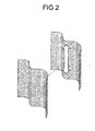
- Fig. 2 shows a relationship between joining surfaces, each of which has a uniform cross-sectional shape.
- the composite materials of the vehicle skeleton member of the invention is preferably joining by vibration welding in a ratio of 50% to 100% of the total joining area of the composite material.
- the definition of the joining area is as described in the above.
- a fastening portion not resulting from vibration welding may be contained but, form the viewpoint of weight-saving, it is preferable to increase the ratio of joining by vibration welding. More preferably, in 70 to 100% of the total joining area, which is achieved by vibration welding.
- number of the joining portions it is preferable that 50% or more of all the portions are joined by vibration welding and further more preferably 80% or more thereof are joined by vibration welding.
- joining methods other than vibration welding in the composite material there are known methods such as a method of using an adhesive agent, a method of mechanically fastening joining with a volt, a nut or the like, a method of adhesion by heating and melting the thermoplastic resin as a matrix resin by a method other than vibration, and these may be used in addition to the vibration welding in the invention.
- clearance is necessary for frictional melting by vibrating the joining surfaces.
- a clearance of about 2 mm is necessary in a vibration direction, such a member shape that the clearance can be provided on a roof rail is selected or, in addition, it is also possible to use a method other than vibration welding in combination in the portion in which the clearance is difficult to be kept.
- various fibers can be used according to the use application of a joined structure but preferred ones include one or more selected from the group consisting of glass fibers, polyester fibers, polyolefin fibers, carbon fibers, para-aramide fibers, meta-aramide fibers, boron fibers, azole fibers, alumina fibers, and the like. Particularly preferred is a carbon fiber excellent in specific strength and specific elasticity.
- the form of the reinforcing fiber in the composite material may be a discontinuous fiber a continuous fiber, or two or more types thereof may be used in combination.
- the discontinuous fiber is specifically a short fiber having a fiber length of 0.1 to less than 10 mm or a long fiber having a fiber length of 10 mm to 100 mm.
- the continuous fiber becomes, needless to say, discontinuous depending on the size and shape of the vehicle skeleton member, so that one having a fiber length of more than 100 mm is regarded as the continuous fiber.
- a form of a paper made using chopped strands or the like or a two-dimensional random mat is preferred.
- the multi axial woven fabric generally means a woven fabric in which one obtained by stacking a bundle of fiber-reinforced material aligned in one direction in a sheet form with changing the angle (multi axial woven fabric base material) is stitched with a stitching thread such as a Nylon thread, a polyester thread, or a glass fiber thread through the stacked body in a thickness direction between the front side and the reverse side of the stacked body along a surface direction, back and forth.
- the fiber-reinforced material included in the fiber-reinforced composite material shaped product may be one in which a reinforcing fibers are randomly spread or one in which a reinforcing fibers are specifically oriented.
- Preferred is one in which a reinforcing fibers are in-plane oriented or oriented in one axis direction, or a combination thereof, or a stacked body thereof.
- the weight ratio of reinforcing fiber/thermoplastic resin in the fiber-reinforced composite material is preferably from 20/80 to 80/20. More preferably, the ratio is from 30/70 to 70/30.
- the thermoplastic resin specifically includes polycarbonate resins, polyolefin resins, polyester resins, acrylic resins, polylactic acid, polyamide resins, ASA resins, ABS resins, polyether ketone resins, polyether imide resins, polyphenylene ether resins, polyphenylene oxide resins, polysulfone resins, polyether sulfone resins, polyether imide resins, polyether ether ketone resins, polyphenylene sulfide resins, polyamide imide resins, and two or more mixtures (resin compositions) selected from these resins but is not particularly limited.
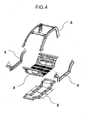
- FIG. 3 is a schematic view showing a vehicle skeleton member that is an example of the invention.
- a vehicle skeleton member 1 in the present example having an underfloor structural component 2, an upperfloor structural component 3, right and left side sill structural components 4 and 5, and a vehicle body upper structural component 6 including pillar-roof rail.
- all of the underfloor structural component 2, the upperfloor structural component 3, the right and left side sill structural components 4 and 5, and the vehicle body upper structural component 6 may be combined to form the vehicle skeleton member or each structural component and/or a complex of two or more structural components may be formed into the vehicle skeleton member.
- Fig. 7 shows cross-sectional shapes of vibration-welded portions of the underfloor structural component 2 and the arrowed places in the cross-sectional view are vibration-welded parts.
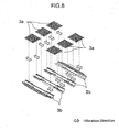
- Fig. 8 and Fig. 9 show assembling methods in the case where the vehicle skeleton member is the upperfloor structural component 3.
- a component 3a and a component 3b are vibration-welded to manufacture a component 3c. After a component 3d and a component 3e are vibration-welded, the resulting one is vibration-welded to the component 3c and also a component 3f is vibration-welded to the component 3c.
- the component 3g may be made a detachable structure as a cover in the case where a battery is housed in a floor or may be jointed to the component 3c by vibration welding.
- the component 3a, the component 3b, and the component 3e may be joined by vibration welding after separately manufactured or may be integrally formed in a mold.
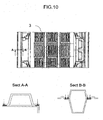
- Fig. 10 shows cross-sectional shapes of the vibration-welded portions of the upperfloor structural component 3 and the arrowed places in the cross-sectional view show vibration-welded parts.
- Fig. 11 shows an assembling method in the case where the vehicle skeleton member is the side sill structural components 4 and 5.
- a component 4a and a component 4b, and a component 5a and a component 5b are vibration-welded and thereafter a component 4c and a component 5c are vibration-welded each other, whereby the side sill structural components 4 and 5 can be manufactured.
- Fig. 12 shows cross-sectional shapes of vibration-welded portions of a side sill structural component 4 and the arrowed places in the cross-sectional view show vibration-welded parts.
- Fig. 13 and Fig. 14 show assembling methods in the case where the vehicle skeleton member is the body upper structural component 6.
- a component 6a and a component 6b are vibration-welded to manufacture one pair of right and left pillars 6c.
- the component 6a and the component 6b may be separately manufactured or may be integrally formed as a hollow entire piece.
- a component 6d and a component 6e are vibration-welded so that the component 6d is sandwiched with the components 6e to manufacture a roof rail 6f, and the pillar 6c and the roof rail 6f are joined by vibration welding.
- the component 6d and the component 6e may be separately manufactured or may be integrally formed.
- Fig. 15 shows a cross-sectional shape of a vibration-welded portion of the body upper structural component 6 and the arrowed places in the cross-sectional view show vibration-welded parts.
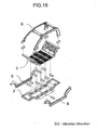
- Fig. 16 shows an assembling method in the case where the underfloor structural component 2, the upperfloor structural component 3, the right and left side sill structural components 4 and 5, and the body upper structural component 6 including pillar-roof rail are integrated to form the vehicle skeleton member.
Description
- The present invention relates to a vehicle skeleton member having a member constituted by a composite material of a thermoplastic resin and a reinforcing fiber. Particularly, it relates to a vehicle skeleton member that is light in weight and excellent in strength.
-
EP0807566A2 relates to a floor structure for truck's load-carrying platform. - A current vehicle skeleton member generally has a structure in which steel is subjected to sheet metal processing and assembled by spot welding.
- Although the vehicle skeleton member has a very complex shape for providing a reinforcing structure for increasing body rigidity and a living space, a large limitation is not needed on the shape of a joint part owing to a robotized spot-welding technology, and therefore a high productivity is enabled.
- On the other hand, in recent years, for decreasing environmental burdens of automobiles, saving of body weight has been strongly desired and application of a carbon fiber composite material to vehicle skeleton members has been attempted. In these vehicle skeleton members made from the carbon fiber composite material, their weight has been drastically saved as compared with the case of existing steel-made vehicle skeleton members. However, since the shapes of the members have to follow complex shape of the existing steel-made vehicle skeleton members, an expensive carbon fiber woven fabric is to be used and shaping thereof is performed by a hand lay-up or autoclave method that is low in productivity. Therefore, from the viewpoint of economic efficiency, wide range of use thereof has been extremely limited. Recently, although an improvement in productivity is attempted using RTM method (Resin Transfer Molding method) or the like (see, Patent Document 1), but it is hard to say that the technology can be applied to general vehicles, since a curing reaction time of a thermosetting resin used as a matrix is rate-limiting.
- Moreover, at the application of the fiber-reinforced composite material to the vehicle skeleton member, the joint of the fiber-reinforced composite materials themselves and the joint of the fiber-reinforced composite material to the other material such as a metal become a problem. Although the fiber-reinforced composite material is light in weight and has a high strength, it is not preferable to apply a local load such as volt fastening, so that there have been proposed a large number of structures for dispersing the load at a fastening portion.
Patent Document 2 shows examples of structures for attaching the fiber-reinforced composite material. The stress concentration at the joint portion can be avoided by these structures, but an improvement in productivity is limited since the structures are complex. - On the other hand, as a means for improving the productivity of fiber-reinforced composite materials, a thermoplastic fiber-reinforced composite material containing a thermoplastic resin used as a matrix has been developed. Such a thermoplastic fiber-reinforced composite material enables shaping within a short tact time by stamping after heated and plasticized. Since pressing pressure required for stamping is lower than that required for stamping molding of steel, integral molding is applicable in the case of such a size as a floor for a vehicle. Moreover, since the thermoplastic fiber-reinforced composite material can be softened by re-heating, it is also one characteristic that jointing by welding is possible.
- (Patent Document 1)
JP-A-2008-68720 - (Patent Document 2)
JP-A-2006-64010 - An object of the present invention is to provide a vehicle skeleton member having a member including a composite material of a thermoplastic resin and a reinforcing fiber, in which a high joint strength is achieved at a joining portion of the composite materials and which has a sufficient strength as a vehicle structure.
- The present inventors have found that the above problem can be solved by constituting a vehicle skeleton member by a fiber-reinforced composite material made of a thermoplastic resin and a reinforcing fiber and joining the composite materials by vibration welding and further by designing a joining surface and a vehicle skeleton structure suitable for the vibration welding. Namely, the invention is a vehicle skeleton member having a portion obtained by joining together a plurality of members containing a composite material of a thermoplastic resin and a reinforcing fiber, and an axis parallel to a front and rear direction of a vehicle body and/or a right and left direction of the vehicle body is included on a surface of the joined portion by vibration welding.
- The vehicle skeleton member of the invention has a portion obtained by joining a plurality of members containing a composite material of a thermoplastic resin and a reinforcing fiber, and an axis parallel to a front and rear direction of a vehicle body and/or a right and left direction of the vehicle body is included in a joining surface. And further, by arranging the joining portion on a flat surface including the axis and/or a curved surface including a uniform cross-sectional shape and the axis, it becomes possible to join a plurality of members simultaneously by vibration welding without providing a vibration welding device and a jig at each of every joining portions. Moreover, since it is possible to obtain a high joint strength for a short period of time through the joining by vibration welding as compared with the joining with a usual adhesive or a metal fastening member is not necessary, a vehicle structure excellent in weight-saving can be obtained in high productivity.
-
-
Fig. 1 is a schematic view showing a planar joining surface and vibration directions. -
Fig. 2 is a schematic view showing a joining surface having a uniform cross-sectional shape and a vibration direction. -
Fig. 3 is a schematic view showing an example of the vehicle skeleton member of the invention. -
Fig. 4 is a schematic view showing a constitution of the vehicle skeleton member of the invention. -
Fig. 5 is a schematic view showing an assembling method in the case where the vehicle skeleton member is an underfloor structural component. -
Fig. 6 is a schematic view showing an assembling method in the case where the vehicle skeleton member is an underfloor structural component. -
Fig. 7 is a schematic view showing cross-sectional shapes of vibration-welded parts of an underfloor structural component. -
Fig. 8 is a schematic view showing an assembling method in the case where the vehicle skeleton member is an upperfloor structural component. -
Fig. 9 is a schematic view showing an assembling method in the case where the vehicle skeleton member is an upperfloor structural component. -
Fig. 10 is a schematic view showing cross-sectional shapes of vibration-welded parts of an upperfloor structural component. -
Fig. 11 is a schematic view showing an assembling method in the case where the vehicle skeleton member is a side sill structural component. -
Fig. 12 is a schematic view showing cross-sectional shapes of vibration-welded parts of a side sill structural component. -
Fig. 13 is a schematic view showing an assembling method in the case where the vehicle skeleton member is a vehicle body upper structural component. -
Fig. 14 is a schematic view showing an assembling method in the case where the vehicle skeleton member is a vehicle body upper structural component. -
Fig. 15 is a schematic view showing a cross-sectional shape of a vibration-welded part of a vehicle body upper structural component. -
Fig. 16 is a schematic view showing an assembling method in the case where the vehicle skeleton member is constituted by integrating individual structural components. -
Fig. 17 is a schematic view showing cross-sectional shapes of vibration-welded parts of an integrated vehicle skeleton member. -
- 1 Vehicle skeleton member
- 2 Underfloor structural component
- (2a, 2b, 2c, 2d: components)
- 3 Upperfloor structural component
- (3a, 3b, 3c, 3d, 3e, 3f, 3g: components)
- 4 Side sill structural component
- (4a, 4b, 4c: components)
- 5 Side sill structural component
- (5a, 5b, 5c: components)
- 6 Vehicle body upper structural component (pillar-roof)
- (6a, 6b, 6c, 6d, 6e, 6f: components)
- The following will explain embodiments of the present invention in sequence.
- The vehicle skeleton member of the invention is a member constituting a vehicle body of an automobile. Specific examples include floor structural components, side sill structural components, vehicle body upper structural components including a pillar, a roof rail, and the like, and complexes thereof. The vehicle skeleton member has members including a composite material of a thermoplastic resin and a reinforcing fiber and has a portion at which these plural members including the composite material are joined. The vehicle skeleton member may have a member including a material other than the composite material, such as a metal, a ceramic, a composite material in which a matrix is a thermosetting resin or the like, in addition to the members including the composite material of the thermoplastic resin and the reinforcing fiber. From the viewpoint of weight-saving, it is preferable that the ratio of the member including the composite material in the vehicle skeleton member is high. Specifically, the weight ratio of the member including the composite material in the vehicle skeleton member is preferably 50% or more and more preferably 80% or more and 100% or less.
- The vibration welding is a method of joining two members (resin components etc.) through melting a resin by frictional heat generated between the two members by periodically vibrating the two members in a contact condition forced by pressurization and can be performed using a known vibration welding machine. In the vehicle skeleton member of the invention, the thermoplastic resin that is a matrix of the composite material is melted by vibration to effect joining.
- The vehicle skeleton member of the invention is characterized in that the vehicle skeleton member is designed so that an axis parallel to a front and rear direction of a vehicle body and/or a right and left direction of the vehicle body is included in a joining surface at which vibration welding is performed. Namely, the vehicle skeleton member of the invention is characterized in that the joining portion is arranged so that the axis parallel to the front and rear direction of the vehicle body and/or the right and left direction of the vehicle body is contained in the joining surface and the vehicle skeleton member has a portion joined by vibration welding. Here, "parallel" is not necessarily "completely parallel" and a shift within substantially about ±10° is allowable. In this case, it is preferable that a plurality of joining surfaces are also shifted at a constant angle.
- In the vehicle skeleton member, a joining surface partly containing no axis parallel to the front and rear direction of the vehicle body and/or the right and left direction of the vehicle body may be present. However, the ratio of the joining surface containing an axis parallel to the front-rear direction of the vehicle body and/or the right-left direction of the vehicle body is preferably from 50 to 100% of the total area of joining portion. Furthermore, the ratio of the joining surface containing the axis parallel to the front-rear direction of the vehicle body and/or the right-left direction of the vehicle body is more preferably 80 to 100% of the total joining area.
- In the present invention, the joining area refers to an area for the joining in design, which is individually set depending on the kind of the joining method at the time of performing strength design of the joining portion between a plurality of components themselves or members themselves or between a component and a member, and is different from the total area of the joining portion. For example, in
Fig. 7 ,Fig. 10 ,Fig. 12 ,Fig. 15 , andFig. 17 , the place shown by an arrow in the cross-sectional view is a vibration welding portion and the total area of these places is the total joining area. In the vehicle skeleton member, the sum of the joining areas of all the joined portions is taken as total joining area. - In the case where the vehicle skeleton member is manufactured in a commercial level, in the vehicle skeleton member, it is preferable that the ratio of the joining surface containing the axis parallel to the front-rear direction of the vehicle body and/or the right-left direction of the vehicle body is high. Specifically, it is preferable that 50% or more of all the joining surfaces contain the axis parallel to the front and rear direction of the vehicle body and/or the right and left direction of the vehicle body. More preferably, 80% or more of all the joining portions contain the axis parallel to the front-rear direction of the vehicle body and/or the right-left direction of the vehicle body.
- In the case that a part of the joining surfaces contain no axis parallel to the front-rear direction and/or the right-left direction of the vehicle body, joining by vibration welding is possible by controlling the direction of the vibration welding device and using a jig each time, and it is also possible to appropriately joining or fastening them by a method other than vibration welding.
- Since a production line of the vehicle body is preferably arranged on the axis parallel to the front and rear direction of the vehicle body and/or the right and left direction of the vehicle body, it is preferable to design the joining surface of the composite materials at the vehicle skeleton member so as to contain the axis parallel to the front and rear direction of the vehicle body and/or the right and left direction of the vehicle body.
- In the case where the vehicle skeleton member is manufactured in a commercial level, a plurality of joining surfaces at the vehicle skeleton member are preferably present in the same direction in view of production efficiency. Specifically, the ratio of the joining surface present in the same direction to the total joining area is preferably from 50 to 100 and more preferably from 80 to 100%. Here, the definition of the joining area is as descried in the above.
- Specifically, with regard to the number of the joining surfaces, it is preferably that 50% or more of all the joining portions are in the same direction and further 80% or more of all the joining portions are in the same direction.
- For joining by vibration welding, the welding surface of the composite material themselves in the vehicle skeleton member is preferably a plane surface and/or a curved surface having a uniform cross-sectional shape. The curved surface having a uniform cross-sectional shape means one having a shape in which a plane surface having a curved line is extruded in parallel. The cross-sectional shape may include a circle, an ellipse, a semicircle, a semicylinder, and the like.
Fig. 1 shows a relationship between a plane joining surface and a vibration direction, but the vibration direction can be arbitrarily selected in the surface.Fig. 2 shows a relationship between joining surfaces, each of which has a uniform cross-sectional shape. In this case, the vibration direction is limited to the extrusion direction of the section. In the case where the joining surface is other than a plane surface and/or a curved surface having a uniform cross-sectional shape, joining or fastening can be appropriately performed by a method other than vibration welding. - The composite materials of the vehicle skeleton member of the invention is preferably joining by vibration welding in a ratio of 50% to 100% of the total joining area of the composite material. Here, the definition of the joining area is as described in the above. In the vehicle skeleton member, a fastening portion not resulting from vibration welding may be contained but, form the viewpoint of weight-saving, it is preferable to increase the ratio of joining by vibration welding. More preferably, in 70 to 100% of the total joining area, which is achieved by vibration welding. Moreover, with regard to number of the joining portions, it is preferable that 50% or more of all the portions are joined by vibration welding and further more preferably 80% or more thereof are joined by vibration welding.
- As joining methods other than vibration welding in the composite material, there are known methods such as a method of using an adhesive agent, a method of mechanically fastening joining with a volt, a nut or the like, a method of adhesion by heating and melting the thermoplastic resin as a matrix resin by a method other than vibration, and these may be used in addition to the vibration welding in the invention.
- In performance of vibration welding, clearance is necessary for frictional melting by vibrating the joining surfaces. For example, in a known vibration welding device, since a clearance of about 2 mm is necessary in a vibration direction, such a member shape that the clearance can be provided on a roof rail is selected or, in addition, it is also possible to use a method other than vibration welding in combination in the portion in which the clearance is difficult to be kept.
- As the reinforcing fiber constituting the composite material, various fibers can be used according to the use application of a joined structure but preferred ones include one or more selected from the group consisting of glass fibers, polyester fibers, polyolefin fibers, carbon fibers, para-aramide fibers, meta-aramide fibers, boron fibers, azole fibers, alumina fibers, and the like. Particularly preferred is a carbon fiber excellent in specific strength and specific elasticity.
- The form of the reinforcing fiber in the composite material may be a discontinuous fiber a continuous fiber, or two or more types thereof may be used in combination. The discontinuous fiber is specifically a short fiber having a fiber length of 0.1 to less than 10 mm or a long fiber having a fiber length of 10 mm to 100 mm. The continuous fiber becomes, needless to say, discontinuous depending on the size and shape of the vehicle skeleton member, so that one having a fiber length of more than 100 mm is regarded as the continuous fiber. In the case of the discontinuous fiber, a form of a paper made using chopped strands or the like or a two-dimensional random mat is preferred. In the case of the continuous fiber, preferred is a sheet-shaped form of a woven or knitted fabric, a unidirectionally oriented sheet-shaped product of strands, a multi axial woven fabric, and the like, or nonwoven fabric-shaped form. In this regard, the multi axial woven fabric generally means a woven fabric in which one obtained by stacking a bundle of fiber-reinforced material aligned in one direction in a sheet form with changing the angle (multi axial woven fabric base material) is stitched with a stitching thread such as a Nylon thread, a polyester thread, or a glass fiber thread through the stacked body in a thickness direction between the front side and the reverse side of the stacked body along a surface direction, back and forth. The fiber-reinforced material included in the fiber-reinforced composite material shaped product may be one in which a reinforcing fibers are randomly spread or one in which a reinforcing fibers are specifically oriented. Preferred is one in which a reinforcing fibers are in-plane oriented or oriented in one axis direction, or a combination thereof, or a stacked body thereof.
- Of these, as the fiber-reinforced composite material, preferred is a random fiber-reinforced composite material in which chopped fibers are randomly oriented in a thermoplastic resin. Furthermore, when it is a two-dimensional random fiber-reinforced composite material in which chopped fibers are two-dimensionally randomly oriented in a thermoplastic resin, the material is extremely excellent in moldability and can be shaped into a vehicle skeleton member having not only a planar shape but also a complex shape including a curve part. A combination of the random fiber-reinforced composite material with another kind of fiber-reinforced composite material or a layer body thereof can be also suitably used for the vehicle skeleton member of the invention. The fiber-reinforced composite material can be a layer composed of a fiber-reinforced composite material and a thermoplastic resin, or a layer body or a sandwiched structure having a fiber-reinforced composite material layer in which the type of the reinforcing fibers are different. In the case of the sandwiched structure, a core member may be a composite material and a skin member may be a resin, and inversely, the core member may be a simple resin material and the skin member may be a composite material.
- The weight ratio of reinforcing fiber/thermoplastic resin in the fiber-reinforced composite material is preferably from 20/80 to 80/20. More preferably, the ratio is from 30/70 to 70/30.
- The thermoplastic resin specifically includes polycarbonate resins, polyolefin resins, polyester resins, acrylic resins, polylactic acid, polyamide resins, ASA resins, ABS resins, polyether ketone resins, polyether imide resins, polyphenylene ether resins, polyphenylene oxide resins, polysulfone resins, polyether sulfone resins, polyether imide resins, polyether ether ketone resins, polyphenylene sulfide resins, polyamide imide resins, and two or more mixtures (resin compositions) selected from these resins but is not particularly limited.
- Specific examples of embodiments of the invention will be explained with reference to
Fig. 3 to Fig. 17 but the invention should not be construed as being limited thereto. -
Fig. 3 is a schematic view showing a vehicle skeleton member that is an example of the invention. Avehicle skeleton member 1 in the present example having an underfloorstructural component 2, an upperfloorstructural component 3, right and left side sillstructural components structural component 6 including pillar-roof rail. As in the present example, all of the underfloorstructural component 2, the upperfloorstructural component 3, the right and left side sillstructural components structural component 6 may be combined to form the vehicle skeleton member or each structural component and/or a complex of two or more structural components may be formed into the vehicle skeleton member. -
Fig. 5 andFig. 6 show assembling methods in the case where the vehicle skeleton member is the underfloorstructural component 2. The underfloorstructural component 2 can be manufactured by vibration-welding a component 2a and a component 2b to manufacture acomponent 2c, and vibration-welding thecomponent 2c to the under surface of acomponent 2d. Here, thecomponent 2c may be manufactured with dividing into the component 2a and the component 2b or may be integrally formed. In the case of vibration welding of thecomponent 2c and thecomponent 2d, since clearance is needed in a front and rear direction and also a rising part of thecomponent 2c cannot be subjected to vibration welding, it is desirable to use a method other than vibration welding in combination. -
Fig. 7 shows cross-sectional shapes of vibration-welded portions of the underfloorstructural component 2 and the arrowed places in the cross-sectional view are vibration-welded parts. -
Fig. 8 andFig. 9 show assembling methods in the case where the vehicle skeleton member is the upperfloorstructural component 3. Acomponent 3a and acomponent 3b are vibration-welded to manufacture acomponent 3c. After acomponent 3d and acomponent 3e are vibration-welded, the resulting one is vibration-welded to thecomponent 3c and also acomponent 3f is vibration-welded to thecomponent 3c. The component 3g may be made a detachable structure as a cover in the case where a battery is housed in a floor or may be jointed to thecomponent 3c by vibration welding. Here, thecomponent 3a, thecomponent 3b, and thecomponent 3e may be joined by vibration welding after separately manufactured or may be integrally formed in a mold.Fig. 10 shows cross-sectional shapes of the vibration-welded portions of the upperfloorstructural component 3 and the arrowed places in the cross-sectional view show vibration-welded parts. -
Fig. 11 shows an assembling method in the case where the vehicle skeleton member is the side sillstructural components component 4a and acomponent 4b, and acomponent 5a and acomponent 5b are vibration-welded and thereafter acomponent 4c and acomponent 5c are vibration-welded each other, whereby the side sillstructural components Fig. 12 shows cross-sectional shapes of vibration-welded portions of a side sillstructural component 4 and the arrowed places in the cross-sectional view show vibration-welded parts. -
Fig. 13 andFig. 14 show assembling methods in the case where the vehicle skeleton member is the body upperstructural component 6. Acomponent 6a and acomponent 6b are vibration-welded to manufacture one pair of right and leftpillars 6c. Here, thecomponent 6a and thecomponent 6b may be separately manufactured or may be integrally formed as a hollow entire piece. Thereafter, acomponent 6d and acomponent 6e are vibration-welded so that thecomponent 6d is sandwiched with thecomponents 6e to manufacture aroof rail 6f, and thepillar 6c and theroof rail 6f are joined by vibration welding. Here, thecomponent 6d and thecomponent 6e may be separately manufactured or may be integrally formed.Fig. 15 shows a cross-sectional shape of a vibration-welded portion of the body upperstructural component 6 and the arrowed places in the cross-sectional view show vibration-welded parts. -
Fig. 16 shows an assembling method in the case where the underfloorstructural component 2, the upperfloorstructural component 3, the right and left side sillstructural components structural component 6 including pillar-roof rail are integrated to form the vehicle skeleton member. - The underfloor
structural component 2 and the side sillstructural components structural component 3 is vibration-welded, and the body upperstructural component 5 is vibration-welded to thereby manufacture the integratedvehicle skeleton member 1.Fig. 17 shows cross-sectional shapes of vibration-welded portions of the integratedvehicle skeleton member 1 and the arrowed places in the cross-sectional view show vibration-welded parts.
Claims (15)
- A vehicle skeleton member (1) comprising
a joined portion obtained by joining, by vibration welding, a plurality of members (2, 3, 4, 5, 6) characterized in that the plurality of members (2, 3, 4, 5, 6) is constituted by a two-dimensionally randomly reinforced composite material of a thermoplastic resin and chopped reinforcing fibers being two-dimensionally randomly orientated,
wherein a joining surface of the joined portion is contained on an axis parallel to a front and rear direction of a vehicle body and/or a right and left direction of the vehicle body. - The vehicle skeleton member according to claim 1,
wherein the joining surface is a plane surface and/or a curved surface having a uniform cross-sectional shape. - The vehicle skeleton member according to claim 1 or 2,
wherein the vehicle skeleton member is a floor structural component. - The vehicle skeleton member according to claims 1 or 2,
wherein the vehicle skeleton member is a side sill structural component. - The vehicle skeleton member according to claims 1 or 2,
wherein the vehicle skeleton member is a body upper structural component. - The vehicle skeleton member according to any one of claims 1 to 5,
wherein the reinforcing fiber is a carbon fiber. - The vehicle skeleton member according to any one of claims 1 to 6,
wherein the ratio of the joining surface present in the direction of an axis parallel to a front and rear direction of a vehicle body and/or a right and left direction of the vehicle body to a total joining area is preferably from 50 to 100%. - The vehicle skeleton member according to any one of claims 1 to 7,
wherein the joined portion includes a joining surface joined by vibration welding of which a vibration direction is the front and rear direction of the vehicle body and another joining surface joined by vibration welding of which a vibration direction is the right and left direction of the vehicle body. - A manufacturing method of a vehicle skeleton member (1), comprising:vibration-welding a plurality of members (2, 3, 4, 5, 6) comprising a two-dimensionally random fiber-reinforced composite material including a thermoplastic resin and chopped reinforcing fibers being two-dimensionally randomly oriented in the thermoplastic resin in an axis direction parallel to a front and rear direction of a vehicle body or to a right and left direction of the vehicle body so as to join the plurality of members at a joining surface.
- The manufacturing method of a vehicle skeleton member according to claim 9,
wherein the joining surface is a plane surface and/or a curved surface having a uniform cross-sectional shape. - The manufacturing method of a vehicle skeleton member according to claim 9 or 10,
wherein a vibration direction is the front and rear direction and the right and left direction. - The manufacturing method of a vehicle skeleton member according to claim 9 or 10,
wherein the vehicle skeleton member is a floor structural component. - The manufacturing method of a vehicle skeleton member according to claim 9 or 10,
wherein the vehicle skeleton member is a side sill structural component. - The manufacturing method of a vehicle skeleton member according to claim 9 or 10,
wherein the vehicle skeleton member is a body upper structural component. - The manufacturing method of a vehicle skeleton member according to any one of claims 9 to 14, wherein the reinforcing fiber is a carbon fiber.
Applications Claiming Priority (2)
| Application Number | Priority Date | Filing Date | Title |
|---|---|---|---|
| JP2011021650 | 2011-02-03 | ||
| PCT/JP2012/052797 WO2012105717A1 (en) | 2011-02-03 | 2012-02-01 | Vehicle skeleton member |
Publications (3)
| Publication Number | Publication Date |
|---|---|
| EP2671780A1 EP2671780A1 (en) | 2013-12-11 |
| EP2671780A4 EP2671780A4 (en) | 2014-04-09 |
| EP2671780B1 true EP2671780B1 (en) | 2015-09-09 |
Family
ID=46602914
Family Applications (1)
| Application Number | Title | Priority Date | Filing Date |
|---|---|---|---|
| EP12742424.0A Not-in-force EP2671780B1 (en) | 2011-02-03 | 2012-02-01 | Vehicle skeleton member |
Country Status (6)
| Country | Link |
|---|---|
| US (1) | US9132859B2 (en) |
| EP (1) | EP2671780B1 (en) |
| JP (2) | JPWO2012105717A1 (en) |
| KR (1) | KR101886897B1 (en) |
| CN (1) | CN103402858A (en) |
| WO (1) | WO2012105717A1 (en) |
Families Citing this family (33)
| Publication number | Priority date | Publication date | Assignee | Title |
|---|---|---|---|---|
| WO2012033000A1 (en) * | 2010-09-06 | 2012-03-15 | 東レ株式会社 | Structure for passenger vehicle interior, and manufacturing method therefor |
| WO2012105717A1 (en) * | 2011-02-03 | 2012-08-09 | 帝人株式会社 | Vehicle skeleton member |
| JP5581404B2 (en) * | 2011-02-03 | 2014-08-27 | 帝人株式会社 | Vehicle floor structure |
| JP5487236B2 (en) * | 2012-04-05 | 2014-05-07 | 本田技研工業株式会社 | Car body side structure |
| DE102012010768A1 (en) * | 2012-05-31 | 2013-12-05 | Decoma (Germany) Gmbh | Structural component for a motor vehicle |
| DE102013006131A1 (en) * | 2013-04-10 | 2014-10-16 | Webasto SE | Roof frame component of a roof opening system of a vehicle |
| DE102013209095A1 (en) * | 2013-05-16 | 2014-11-20 | Bayerische Motoren Werke Aktiengesellschaft | Crash structure for a vehicle |
| WO2014203782A1 (en) * | 2013-06-21 | 2014-12-24 | 帝人株式会社 | Vehicle of monocoque construction formed from thermoplastic resin members |
| DE102013214782A1 (en) * | 2013-07-29 | 2015-01-29 | Bayerische Motoren Werke Aktiengesellschaft | Vehicle body with two glued body components |
| US20150108793A1 (en) * | 2013-10-21 | 2015-04-23 | Teijin Limited | Carbon fiber cross member for automotive chassis structure |
| KR101611022B1 (en) * | 2014-03-04 | 2016-04-11 | 현대자동차주식회사 | Upper-body frame system for vehicle |
| KR101558745B1 (en) * | 2014-03-04 | 2015-10-07 | 현대자동차주식회사 | Under-floor frame system for vehicle |
| WO2015141588A1 (en) * | 2014-03-18 | 2015-09-24 | 帝人株式会社 | Hollow structural body and component for vehicles |
| US9650003B2 (en) | 2014-07-02 | 2017-05-16 | GM Global Technology Operations LLC | Impact resistant component for a vehicle |
| US9592853B2 (en) | 2014-07-02 | 2017-03-14 | GM Global Technology Operations LLC | Corrugation designs |
| US9187136B1 (en) * | 2014-08-01 | 2015-11-17 | Honda Motor Co., Ltd. | Structural pan for automotive body/frame |
| US10160172B2 (en) | 2014-08-06 | 2018-12-25 | GM Global Technology Operations LLC | Mechanical interlocking realized through induction heating for polymeric composite repair |
| US9878489B2 (en) | 2014-12-18 | 2018-01-30 | GM Global Technology Operations LLC | Spin-welding of polymeric components having large surface area or non-complementary weld interfaces |
| DE102015100968A1 (en) * | 2015-01-23 | 2016-07-28 | Dr. Ing. H.C. F. Porsche Aktiengesellschaft | Method for producing a motor vehicle body in mixed construction |
| DE102015103006A1 (en) * | 2015-03-03 | 2016-09-08 | Dr. Ing. H.C. F. Porsche Aktiengesellschaft | Side skirts for a motor vehicle with a sill panel |
| DE102015204494A1 (en) * | 2015-03-12 | 2016-09-15 | Hyundai Motor Company | Hybrid side skirts for a motor vehicle and manufacturing method thereof |
| JP6651318B2 (en) | 2015-09-25 | 2020-02-19 | スズキ株式会社 | Vehicle floor panels |
| FR3042160B1 (en) * | 2015-10-13 | 2017-10-20 | Renault Sas | CAGE SIDING ELEMENT FOR HINGING A BAY ENCLOSURE AND AT LEAST ONE PART OF A BRANCH |
| US10695993B2 (en) | 2016-01-15 | 2020-06-30 | GM Global Technology Operations LLC | In-situ polymerization of polyamides for composite part repair |
| US9988102B2 (en) * | 2016-02-18 | 2018-06-05 | New England Wheels, Inc. | Modular vehicle |
| JP6312736B2 (en) * | 2016-04-19 | 2018-04-18 | 本田技研工業株式会社 | Auto body structure |
| US10589477B2 (en) | 2016-05-02 | 2020-03-17 | GM Global Technology Operations LLC | Cosmetic repair of a thermoplastic carbon fiber composite |
| KR102588926B1 (en) * | 2016-12-13 | 2023-10-17 | 현대자동차주식회사 | Car body understructure |
| IT201600130313A1 (en) | 2016-12-22 | 2018-06-22 | Automobili Lamborghini Spa | CARRYING STRUCTURE OF VEHICLE |
| US10611104B2 (en) | 2017-06-15 | 2020-04-07 | GM Global Technology Operations LLC | Heating elements for repair of molding defects for carbon fiber thermoplastic composites |
| KR20220121323A (en) * | 2021-02-25 | 2022-09-01 | 현대자동차주식회사 | Underbody for vehicle |
| US20230054062A1 (en) * | 2021-08-18 | 2023-02-23 | GM Global Technology Operations LLC | Transparent composite for a vehicle roof |
| CN114670926B (en) * | 2022-04-11 | 2023-08-08 | 北京汽车集团越野车有限公司 | Web type frame assembly |
Family Cites Families (46)
| Publication number | Priority date | Publication date | Assignee | Title |
|---|---|---|---|---|
| JPS61166776A (en) * | 1985-01-18 | 1986-07-28 | Honda Motor Co Ltd | Body for miniature car |
| JPS6360743A (en) * | 1986-09-02 | 1988-03-16 | 東レ株式会社 | Light-weight composite material |
| JPS63232083A (en) * | 1987-03-20 | 1988-09-28 | Honda Motor Co Ltd | Floor structure for automobile |
| JPS6432982A (en) * | 1987-07-28 | 1989-02-02 | Mazda Motor | Resin car body structure of automobile |
| DE3915991A1 (en) | 1989-05-17 | 1990-11-22 | Lemfoerder Metallwaren Ag | TRACK ROD FOR MOTOR VEHICLES |
| JPH0733987Y2 (en) * | 1989-06-20 | 1995-08-02 | 本田技研工業株式会社 | Vehicle body structure consisting of sandwich structure |
| JPH04135720A (en) * | 1990-09-27 | 1992-05-11 | Mazda Motor Corp | Manufacture of fiber-reinforced resin molded object |
| JPH0640807U (en) * | 1992-10-30 | 1994-05-31 | ティーディーケイ株式会社 | Displacement sensor |
| JPH06278660A (en) * | 1993-03-30 | 1994-10-04 | Mazda Motor Corp | Cabin structure for automobile |
| JP3211589B2 (en) * | 1994-11-09 | 2001-09-25 | トヨタ自動車株式会社 | Vibration welding mold for resin products |
| JP3211592B2 (en) * | 1994-11-21 | 2001-09-25 | トヨタ自動車株式会社 | Method of manufacturing resin products |
| US6092862A (en) * | 1996-05-14 | 2000-07-25 | Isuzu Motors Limited | Floor structure for truck's load-carrying platform |
| US6206458B1 (en) * | 1999-09-13 | 2001-03-27 | Daimlerchrysler Corporation | Vehicle body structure |
| DE50004943D1 (en) * | 1999-10-20 | 2004-02-05 | Rcc Regional Compact Car Ag Ku | VEHICLE CELL MADE OF FIBER REINFORCED THERMOPLASTIC PLASTIC |
| US6296301B1 (en) * | 1999-12-21 | 2001-10-02 | Daimlerchrysler Corporation | Motor vehicle body structure using a woven fiber |
| US6648402B2 (en) * | 2000-02-22 | 2003-11-18 | Delphi Technologies, Inc. | Structural support brace |
| JP2003118651A (en) * | 2001-10-12 | 2003-04-23 | Kansai Paint Co Ltd | Manufacturing method of automobile body |
| US6817651B2 (en) * | 2002-05-01 | 2004-11-16 | Schlegel Corporation | Modular vehicular window seal assembly |
| US7128360B2 (en) * | 2002-12-10 | 2006-10-31 | Delphi Technologies, Inc. | Structural hybrid attachment system and method |
| EP1772356B9 (en) * | 2003-01-24 | 2012-07-18 | Club Car, LLC | Composite body for a golf car and utility vehicle |
| JP4297758B2 (en) * | 2003-09-04 | 2009-07-15 | 株式会社アルファ | Locking device |
| EP1714856B1 (en) * | 2004-01-23 | 2012-03-14 | Toray Industries, Inc. | Frp panel for automobile |
| JP4291706B2 (en) * | 2004-02-13 | 2009-07-08 | カルソニックカンセイ株式会社 | Cross car beam for vehicles |
| JP5250972B2 (en) | 2004-02-27 | 2013-07-31 | 東レ株式会社 | Epoxy resin composition for carbon fiber reinforced composite material, prepreg, integrated molded product, fiber reinforced composite material plate, and casing for electric / electronic device |
| JP2005317942A (en) * | 2004-03-29 | 2005-11-10 | Toray Ind Inc | Electrical/electronic equipment |
| JP2005297417A (en) * | 2004-04-14 | 2005-10-27 | Toray Ind Inc | Industrial structure member and its manufacturing method |
| JP2006044260A (en) * | 2004-07-07 | 2006-02-16 | Toray Ind Inc | Integrated structural member and its manufacturing method |
| JP4774839B2 (en) * | 2004-07-08 | 2011-09-14 | 東レ株式会社 | Manufacturing method of fiber reinforced composite material |
| JP2006064010A (en) | 2004-08-24 | 2006-03-09 | Toyota Motor Corp | Fiber reinforced plastic mounting structure |
| US8066321B2 (en) * | 2005-11-21 | 2011-11-29 | Kevin Lusk | Structural shear plate for a vehicle |
| CA2688924C (en) * | 2005-11-21 | 2012-12-04 | Faroex Ltd. | Joint for a composite vehicle body |
| JP4988230B2 (en) * | 2006-03-30 | 2012-08-01 | 帝人テクノプロダクツ株式会社 | Fiber reinforced thermoplastic resin sheet and method for producing the same |
| JP2007313778A (en) * | 2006-05-26 | 2007-12-06 | Teijin Techno Products Ltd | Joining method of fiber-reinforced thermoplastic resin composite material |
| JP4788539B2 (en) | 2006-09-13 | 2011-10-05 | トヨタ自動車株式会社 | Body panel structure |
| JP2008143936A (en) * | 2006-12-06 | 2008-06-26 | Toyota Motor Corp | Adhesion part structure |
| JP2008143358A (en) * | 2006-12-11 | 2008-06-26 | Toyota Motor Corp | Bonded part structure |
| JP4853315B2 (en) * | 2007-02-13 | 2012-01-11 | トヨタ自動車株式会社 | Body frame structure |
| CN102056971B (en) | 2008-07-31 | 2013-09-04 | 东丽株式会社 | Prepreg, preform, molded product, and method for manufacturing prepreg |
| JP4862913B2 (en) * | 2009-03-31 | 2012-01-25 | 東レ株式会社 | Prepregs and preforms |
| DE102009005763A1 (en) * | 2009-01-23 | 2010-07-29 | Lanxess Deutschland Gmbh | Frame side part of a motor vehicle body |
| US20120104803A1 (en) * | 2010-10-29 | 2012-05-03 | Aptera Motors, Inc. | Automotive vehicle composite body structure |
| KR20140001987A (en) * | 2011-01-28 | 2014-01-07 | 데이진 가부시키가이샤 | Joined body of carbon fiber reinforced composite material |
| JP5581404B2 (en) * | 2011-02-03 | 2014-08-27 | 帝人株式会社 | Vehicle floor structure |
| WO2012105717A1 (en) * | 2011-02-03 | 2012-08-09 | 帝人株式会社 | Vehicle skeleton member |
| JPWO2012105716A1 (en) * | 2011-02-03 | 2014-07-03 | 帝人株式会社 | Vehicle frame member |
| JP5889120B2 (en) * | 2012-06-15 | 2016-03-22 | 三菱電機株式会社 | Broadcast program reservation recording device |
-
2012
- 2012-02-01 WO PCT/JP2012/052797 patent/WO2012105717A1/en active Application Filing
- 2012-02-01 CN CN2012800077712A patent/CN103402858A/en active Pending
- 2012-02-01 KR KR1020137020482A patent/KR101886897B1/en active IP Right Grant
- 2012-02-01 JP JP2012556006A patent/JPWO2012105717A1/en active Pending
- 2012-02-01 EP EP12742424.0A patent/EP2671780B1/en not_active Not-in-force
-
2013
- 2013-08-02 US US13/957,487 patent/US9132859B2/en not_active Expired - Fee Related
-
2015
- 2015-12-14 JP JP2015242979A patent/JP6286411B2/en not_active Expired - Fee Related
Also Published As
| Publication number | Publication date |
|---|---|
| WO2012105717A1 (en) | 2012-08-09 |
| EP2671780A4 (en) | 2014-04-09 |
| EP2671780A1 (en) | 2013-12-11 |
| KR101886897B1 (en) | 2018-08-08 |
| US20130313863A1 (en) | 2013-11-28 |
| JP2016055867A (en) | 2016-04-21 |
| KR20140012973A (en) | 2014-02-04 |
| JPWO2012105717A1 (en) | 2014-07-03 |
| US9132859B2 (en) | 2015-09-15 |
| CN103402858A (en) | 2013-11-20 |
| JP6286411B2 (en) | 2018-02-28 |
Similar Documents
| Publication | Publication Date | Title |
|---|---|---|
| EP2671780B1 (en) | Vehicle skeleton member | |
| KR101764463B1 (en) | Vehicle floor structure | |
| US8991900B2 (en) | Vehicle skeleton member | |
| JP4318381B2 (en) | Manufacturing method of fuselage structure made of fiber reinforced composite material, and fuselage structure manufactured thereby | |
| KR101315741B1 (en) | Battery Pack Case Assembly for Electric Vehicles Using Plastic Composite and method for manufacturing the same | |
| CN107107486B (en) | Method for producing a hybrid structural component of a motor vehicle and corresponding hybrid structural component | |
| KR20140039338A (en) | Seat back frame for vehicle and method for manufacturing same | |
| KR101945560B1 (en) | front end module carrier using continuous fiber reinforced thermoplastics and method of manufacturing | |
| US10052851B2 (en) | Fiber reinforced plastic member for vehicle and method of producing the same | |
| JP2020124837A (en) | Edge structure of fiber reinforced resin structure | |
| EP2825366B1 (en) | Composite structural element and method | |
| JP6261202B2 (en) | FRP molded product manufacturing method and FRP molded product | |
| KR102009793B1 (en) | Seat back frame and method of manufacturing the same | |
| JP5179952B2 (en) | Hollow molded product and method for producing hollow molded product | |
| CN109922944B (en) | Method for producing an improved hybrid structural component for a motor vehicle and corresponding hybrid structural component | |
| JP2004339778A (en) | Door and its manufacturing method | |
| JP2019077061A (en) | Resin structure and method for producing the same | |
| JP5835192B2 (en) | Manufacturing method and manufacturing apparatus for thermoplastic resin composite member | |
| JP2019171619A (en) | Reinforced metal member and method for producing the same |
Legal Events
| Date | Code | Title | Description |
|---|---|---|---|
| PUAI | Public reference made under article 153(3) epc to a published international application that has entered the european phase |
Free format text: ORIGINAL CODE: 0009012 |
|
| 17P | Request for examination filed |
Effective date: 20130903 |
|
| AK | Designated contracting states |
Kind code of ref document: A1 Designated state(s): AL AT BE BG CH CY CZ DE DK EE ES FI FR GB GR HR HU IE IS IT LI LT LU LV MC MK MT NL NO PL PT RO RS SE SI SK SM TR |
|
| A4 | Supplementary search report drawn up and despatched |
Effective date: 20140306 |
|
| RIC1 | Information provided on ipc code assigned before grant |
Ipc: B29C 65/06 20060101ALI20140228BHEP Ipc: B62D 29/04 20060101AFI20140228BHEP Ipc: B29K 507/04 20060101ALI20140228BHEP Ipc: B62D 25/06 20060101ALI20140228BHEP Ipc: B62D 25/04 20060101ALI20140228BHEP Ipc: B29K 105/16 20060101ALI20140228BHEP Ipc: B62D 25/20 20060101ALI20140228BHEP |
|
| 17Q | First examination report despatched |
Effective date: 20140408 |
|
| DAX | Request for extension of the european patent (deleted) | ||
| GRAP | Despatch of communication of intention to grant a patent |
Free format text: ORIGINAL CODE: EPIDOSNIGR1 |
|
| INTG | Intention to grant announced |
Effective date: 20150327 |
|
| GRAS | Grant fee paid |
Free format text: ORIGINAL CODE: EPIDOSNIGR3 |
|
| GRAA | (expected) grant |
Free format text: ORIGINAL CODE: 0009210 |
|
| AK | Designated contracting states |
Kind code of ref document: B1 Designated state(s): AL AT BE BG CH CY CZ DE DK EE ES FI FR GB GR HR HU IE IS IT LI LT LU LV MC MK MT NL NO PL PT RO RS SE SI SK SM TR |
|
| REG | Reference to a national code |
Ref country code: GB Ref legal event code: FG4D |
|
| REG | Reference to a national code |
Ref country code: AT Ref legal event code: REF Ref document number: 747878 Country of ref document: AT Kind code of ref document: T Effective date: 20150915 Ref country code: CH Ref legal event code: EP |
|
| REG | Reference to a national code |
Ref country code: IE Ref legal event code: FG4D |
|
| REG | Reference to a national code |
Ref country code: DE Ref legal event code: R096 Ref document number: 602012010443 Country of ref document: DE |
|
| REG | Reference to a national code |
Ref country code: FR Ref legal event code: PLFP Year of fee payment: 5 |
|
| REG | Reference to a national code |
Ref country code: NL Ref legal event code: MP Effective date: 20150909 |
|
| PG25 | Lapsed in a contracting state [announced via postgrant information from national office to epo] |
Ref country code: NO Free format text: LAPSE BECAUSE OF FAILURE TO SUBMIT A TRANSLATION OF THE DESCRIPTION OR TO PAY THE FEE WITHIN THE PRESCRIBED TIME-LIMIT Effective date: 20151209 Ref country code: LT Free format text: LAPSE BECAUSE OF FAILURE TO SUBMIT A TRANSLATION OF THE DESCRIPTION OR TO PAY THE FEE WITHIN THE PRESCRIBED TIME-LIMIT Effective date: 20150909 Ref country code: GR Free format text: LAPSE BECAUSE OF FAILURE TO SUBMIT A TRANSLATION OF THE DESCRIPTION OR TO PAY THE FEE WITHIN THE PRESCRIBED TIME-LIMIT Effective date: 20151210 Ref country code: FI Free format text: LAPSE BECAUSE OF FAILURE TO SUBMIT A TRANSLATION OF THE DESCRIPTION OR TO PAY THE FEE WITHIN THE PRESCRIBED TIME-LIMIT Effective date: 20150909 Ref country code: LV Free format text: LAPSE BECAUSE OF FAILURE TO SUBMIT A TRANSLATION OF THE DESCRIPTION OR TO PAY THE FEE WITHIN THE PRESCRIBED TIME-LIMIT Effective date: 20150909 |
|
| REG | Reference to a national code |
Ref country code: LT Ref legal event code: MG4D |
|
| REG | Reference to a national code |
Ref country code: AT Ref legal event code: MK05 Ref document number: 747878 Country of ref document: AT Kind code of ref document: T Effective date: 20150909 |
|
| PG25 | Lapsed in a contracting state [announced via postgrant information from national office to epo] |
Ref country code: RS Free format text: LAPSE BECAUSE OF FAILURE TO SUBMIT A TRANSLATION OF THE DESCRIPTION OR TO PAY THE FEE WITHIN THE PRESCRIBED TIME-LIMIT Effective date: 20150909 Ref country code: ES Free format text: LAPSE BECAUSE OF FAILURE TO SUBMIT A TRANSLATION OF THE DESCRIPTION OR TO PAY THE FEE WITHIN THE PRESCRIBED TIME-LIMIT Effective date: 20150909 Ref country code: HR Free format text: LAPSE BECAUSE OF FAILURE TO SUBMIT A TRANSLATION OF THE DESCRIPTION OR TO PAY THE FEE WITHIN THE PRESCRIBED TIME-LIMIT Effective date: 20150909 Ref country code: SE Free format text: LAPSE BECAUSE OF FAILURE TO SUBMIT A TRANSLATION OF THE DESCRIPTION OR TO PAY THE FEE WITHIN THE PRESCRIBED TIME-LIMIT Effective date: 20150909 |
|
| PG25 | Lapsed in a contracting state [announced via postgrant information from national office to epo] |
Ref country code: NL Free format text: LAPSE BECAUSE OF FAILURE TO SUBMIT A TRANSLATION OF THE DESCRIPTION OR TO PAY THE FEE WITHIN THE PRESCRIBED TIME-LIMIT Effective date: 20150909 |
|
| PG25 | Lapsed in a contracting state [announced via postgrant information from national office to epo] |
Ref country code: EE Free format text: LAPSE BECAUSE OF FAILURE TO SUBMIT A TRANSLATION OF THE DESCRIPTION OR TO PAY THE FEE WITHIN THE PRESCRIBED TIME-LIMIT Effective date: 20150909 Ref country code: SK Free format text: LAPSE BECAUSE OF FAILURE TO SUBMIT A TRANSLATION OF THE DESCRIPTION OR TO PAY THE FEE WITHIN THE PRESCRIBED TIME-LIMIT Effective date: 20150909 Ref country code: IT Free format text: LAPSE BECAUSE OF FAILURE TO SUBMIT A TRANSLATION OF THE DESCRIPTION OR TO PAY THE FEE WITHIN THE PRESCRIBED TIME-LIMIT Effective date: 20150909 Ref country code: IS Free format text: LAPSE BECAUSE OF FAILURE TO SUBMIT A TRANSLATION OF THE DESCRIPTION OR TO PAY THE FEE WITHIN THE PRESCRIBED TIME-LIMIT Effective date: 20160109 Ref country code: CZ Free format text: LAPSE BECAUSE OF FAILURE TO SUBMIT A TRANSLATION OF THE DESCRIPTION OR TO PAY THE FEE WITHIN THE PRESCRIBED TIME-LIMIT Effective date: 20150909 |
|
| PG25 | Lapsed in a contracting state [announced via postgrant information from national office to epo] |
Ref country code: PL Free format text: LAPSE BECAUSE OF FAILURE TO SUBMIT A TRANSLATION OF THE DESCRIPTION OR TO PAY THE FEE WITHIN THE PRESCRIBED TIME-LIMIT Effective date: 20150909 Ref country code: BE Free format text: LAPSE BECAUSE OF NON-PAYMENT OF DUE FEES Effective date: 20160229 Ref country code: PT Free format text: LAPSE BECAUSE OF FAILURE TO SUBMIT A TRANSLATION OF THE DESCRIPTION OR TO PAY THE FEE WITHIN THE PRESCRIBED TIME-LIMIT Effective date: 20160111 Ref country code: RO Free format text: LAPSE BECAUSE OF FAILURE TO SUBMIT A TRANSLATION OF THE DESCRIPTION OR TO PAY THE FEE WITHIN THE PRESCRIBED TIME-LIMIT Effective date: 20150909 Ref country code: AT Free format text: LAPSE BECAUSE OF FAILURE TO SUBMIT A TRANSLATION OF THE DESCRIPTION OR TO PAY THE FEE WITHIN THE PRESCRIBED TIME-LIMIT Effective date: 20150909 |
|
| REG | Reference to a national code |
Ref country code: DE Ref legal event code: R097 Ref document number: 602012010443 Country of ref document: DE |
|
| PLBE | No opposition filed within time limit |
Free format text: ORIGINAL CODE: 0009261 |
|
| STAA | Information on the status of an ep patent application or granted ep patent |
Free format text: STATUS: NO OPPOSITION FILED WITHIN TIME LIMIT |
|
| 26N | No opposition filed |
Effective date: 20160610 |
|
| PG25 | Lapsed in a contracting state [announced via postgrant information from national office to epo] |
Ref country code: DK Free format text: LAPSE BECAUSE OF FAILURE TO SUBMIT A TRANSLATION OF THE DESCRIPTION OR TO PAY THE FEE WITHIN THE PRESCRIBED TIME-LIMIT Effective date: 20150909 Ref country code: SI Free format text: LAPSE BECAUSE OF FAILURE TO SUBMIT A TRANSLATION OF THE DESCRIPTION OR TO PAY THE FEE WITHIN THE PRESCRIBED TIME-LIMIT Effective date: 20150909 |
|
| PG25 | Lapsed in a contracting state [announced via postgrant information from national office to epo] |
Ref country code: MC Free format text: LAPSE BECAUSE OF FAILURE TO SUBMIT A TRANSLATION OF THE DESCRIPTION OR TO PAY THE FEE WITHIN THE PRESCRIBED TIME-LIMIT Effective date: 20150909 Ref country code: LU Free format text: LAPSE BECAUSE OF FAILURE TO SUBMIT A TRANSLATION OF THE DESCRIPTION OR TO PAY THE FEE WITHIN THE PRESCRIBED TIME-LIMIT Effective date: 20160201 |
|
| REG | Reference to a national code |
Ref country code: CH Ref legal event code: PL |
|
| PG25 | Lapsed in a contracting state [announced via postgrant information from national office to epo] |
Ref country code: LI Free format text: LAPSE BECAUSE OF NON-PAYMENT OF DUE FEES Effective date: 20160229 Ref country code: CH Free format text: LAPSE BECAUSE OF NON-PAYMENT OF DUE FEES Effective date: 20160229 |
|
| REG | Reference to a national code |
Ref country code: IE Ref legal event code: MM4A |
|
| PG25 | Lapsed in a contracting state [announced via postgrant information from national office to epo] |
Ref country code: BE Free format text: LAPSE BECAUSE OF FAILURE TO SUBMIT A TRANSLATION OF THE DESCRIPTION OR TO PAY THE FEE WITHIN THE PRESCRIBED TIME-LIMIT Effective date: 20150909 |
|
| PG25 | Lapsed in a contracting state [announced via postgrant information from national office to epo] |
Ref country code: IE Free format text: LAPSE BECAUSE OF NON-PAYMENT OF DUE FEES Effective date: 20160201 |
|
| REG | Reference to a national code |
Ref country code: FR Ref legal event code: PLFP Year of fee payment: 6 |
|
| PG25 | Lapsed in a contracting state [announced via postgrant information from national office to epo] |
Ref country code: MT Free format text: LAPSE BECAUSE OF FAILURE TO SUBMIT A TRANSLATION OF THE DESCRIPTION OR TO PAY THE FEE WITHIN THE PRESCRIBED TIME-LIMIT Effective date: 20150909 |
|
| REG | Reference to a national code |
Ref country code: FR Ref legal event code: PLFP Year of fee payment: 7 |
|
| PG25 | Lapsed in a contracting state [announced via postgrant information from national office to epo] |
Ref country code: SM Free format text: LAPSE BECAUSE OF FAILURE TO SUBMIT A TRANSLATION OF THE DESCRIPTION OR TO PAY THE FEE WITHIN THE PRESCRIBED TIME-LIMIT Effective date: 20150909 Ref country code: HU Free format text: LAPSE BECAUSE OF FAILURE TO SUBMIT A TRANSLATION OF THE DESCRIPTION OR TO PAY THE FEE WITHIN THE PRESCRIBED TIME-LIMIT; INVALID AB INITIO Effective date: 20120201 Ref country code: CY Free format text: LAPSE BECAUSE OF FAILURE TO SUBMIT A TRANSLATION OF THE DESCRIPTION OR TO PAY THE FEE WITHIN THE PRESCRIBED TIME-LIMIT Effective date: 20150909 |
|
| PG25 | Lapsed in a contracting state [announced via postgrant information from national office to epo] |
Ref country code: MT Free format text: LAPSE BECAUSE OF FAILURE TO SUBMIT A TRANSLATION OF THE DESCRIPTION OR TO PAY THE FEE WITHIN THE PRESCRIBED TIME-LIMIT Effective date: 20160229 Ref country code: TR Free format text: LAPSE BECAUSE OF FAILURE TO SUBMIT A TRANSLATION OF THE DESCRIPTION OR TO PAY THE FEE WITHIN THE PRESCRIBED TIME-LIMIT Effective date: 20150909 Ref country code: MK Free format text: LAPSE BECAUSE OF FAILURE TO SUBMIT A TRANSLATION OF THE DESCRIPTION OR TO PAY THE FEE WITHIN THE PRESCRIBED TIME-LIMIT Effective date: 20150909 |
|
| PG25 | Lapsed in a contracting state [announced via postgrant information from national office to epo] |
Ref country code: BG Free format text: LAPSE BECAUSE OF FAILURE TO SUBMIT A TRANSLATION OF THE DESCRIPTION OR TO PAY THE FEE WITHIN THE PRESCRIBED TIME-LIMIT Effective date: 20150909 |
|
| PG25 | Lapsed in a contracting state [announced via postgrant information from national office to epo] |
Ref country code: AL Free format text: LAPSE BECAUSE OF FAILURE TO SUBMIT A TRANSLATION OF THE DESCRIPTION OR TO PAY THE FEE WITHIN THE PRESCRIBED TIME-LIMIT Effective date: 20150909 |
|
| PGFP | Annual fee paid to national office [announced via postgrant information from national office to epo] |
Ref country code: GB Payment date: 20211209 Year of fee payment: 11 Ref country code: FR Payment date: 20211217 Year of fee payment: 11 |
|
| PGFP | Annual fee paid to national office [announced via postgrant information from national office to epo] |
Ref country code: DE Payment date: 20211207 Year of fee payment: 11 |
|
| REG | Reference to a national code |
Ref country code: DE Ref legal event code: R119 Ref document number: 602012010443 Country of ref document: DE |
|
| GBPC | Gb: european patent ceased through non-payment of renewal fee |
Effective date: 20230201 |
|
| PG25 | Lapsed in a contracting state [announced via postgrant information from national office to epo] |
Ref country code: GB Free format text: LAPSE BECAUSE OF NON-PAYMENT OF DUE FEES Effective date: 20230201 |
|
| PG25 | Lapsed in a contracting state [announced via postgrant information from national office to epo] |
Ref country code: GB Free format text: LAPSE BECAUSE OF NON-PAYMENT OF DUE FEES Effective date: 20230201 Ref country code: FR Free format text: LAPSE BECAUSE OF NON-PAYMENT OF DUE FEES Effective date: 20230228 Ref country code: DE Free format text: LAPSE BECAUSE OF NON-PAYMENT OF DUE FEES Effective date: 20230901 |