WO2012105512A1 - 太陽電池用表面保護材及びそれを用いて作製された太陽電池モジュール - Google Patents
太陽電池用表面保護材及びそれを用いて作製された太陽電池モジュール Download PDFInfo
- Publication number
- WO2012105512A1 WO2012105512A1 PCT/JP2012/052019 JP2012052019W WO2012105512A1 WO 2012105512 A1 WO2012105512 A1 WO 2012105512A1 JP 2012052019 W JP2012052019 W JP 2012052019W WO 2012105512 A1 WO2012105512 A1 WO 2012105512A1
- Authority
- WO
- WIPO (PCT)
- Prior art keywords
- film
- protective material
- solar cell
- moisture
- surface protective
- Prior art date
Links
- 239000000463 material Substances 0.000 title claims abstract description 200
- 230000001681 protective effect Effects 0.000 title claims abstract description 162
- 239000010408 film Substances 0.000 claims abstract description 312
- 239000010409 thin film Substances 0.000 claims abstract description 53
- 238000002844 melting Methods 0.000 claims abstract description 34
- 230000008018 melting Effects 0.000 claims abstract description 34
- 230000005540 biological transmission Effects 0.000 claims abstract description 24
- 210000004027 cell Anatomy 0.000 claims description 133
- 229920005989 resin Polymers 0.000 claims description 95
- 239000011347 resin Substances 0.000 claims description 95
- 239000010410 layer Substances 0.000 claims description 91
- -1 polyethylene Polymers 0.000 claims description 84
- 229920001155 polypropylene Polymers 0.000 claims description 48
- 239000004743 Polypropylene Substances 0.000 claims description 47
- 239000003566 sealing material Substances 0.000 claims description 43
- XLYOFNOQVPJJNP-UHFFFAOYSA-N water Chemical compound O XLYOFNOQVPJJNP-UHFFFAOYSA-N 0.000 claims description 36
- 238000002425 crystallisation Methods 0.000 claims description 34
- 230000008025 crystallization Effects 0.000 claims description 34
- 239000002667 nucleating agent Substances 0.000 claims description 19
- 239000000758 substrate Substances 0.000 claims description 17
- 239000002985 plastic film Substances 0.000 claims description 16
- 229920006255 plastic film Polymers 0.000 claims description 16
- 230000035699 permeability Effects 0.000 claims description 13
- 229920002620 polyvinyl fluoride Polymers 0.000 claims description 10
- 239000002033 PVDF binder Substances 0.000 claims description 8
- 229920005629 polypropylene homopolymer Polymers 0.000 claims description 8
- 229920002981 polyvinylidene fluoride Polymers 0.000 claims description 8
- 239000012790 adhesive layer Substances 0.000 claims description 7
- 229920001225 polyester resin Polymers 0.000 claims description 5
- 239000004645 polyester resin Substances 0.000 claims description 5
- 239000004626 polylactic acid Substances 0.000 claims description 5
- 239000004698 Polyethylene Substances 0.000 claims description 4
- 229920000573 polyethylene Polymers 0.000 claims description 4
- 229920000747 poly(lactic acid) Polymers 0.000 claims description 2
- 238000000034 method Methods 0.000 description 47
- 238000003475 lamination Methods 0.000 description 41
- 238000012360 testing method Methods 0.000 description 37
- 239000000853 adhesive Substances 0.000 description 31
- 230000001070 adhesive effect Effects 0.000 description 30
- 229920000139 polyethylene terephthalate Polymers 0.000 description 24
- 239000005020 polyethylene terephthalate Substances 0.000 description 24
- 239000006097 ultraviolet radiation absorber Substances 0.000 description 20
- 238000000576 coating method Methods 0.000 description 17
- 230000006866 deterioration Effects 0.000 description 17
- 239000011248 coating agent Substances 0.000 description 16
- 238000010438 heat treatment Methods 0.000 description 16
- 230000008569 process Effects 0.000 description 15
- 239000011342 resin composition Substances 0.000 description 15
- 238000004519 manufacturing process Methods 0.000 description 14
- 230000000052 comparative effect Effects 0.000 description 13
- 229920005862 polyol Polymers 0.000 description 13
- 150000003077 polyols Chemical class 0.000 description 12
- 239000011229 interlayer Substances 0.000 description 11
- 229920002635 polyurethane Polymers 0.000 description 11
- 239000011521 glass Substances 0.000 description 10
- 239000003381 stabilizer Substances 0.000 description 10
- 239000003795 chemical substances by application Substances 0.000 description 9
- 239000007788 liquid Substances 0.000 description 9
- 229920001684 low density polyethylene Polymers 0.000 description 9
- 239000004702 low-density polyethylene Substances 0.000 description 9
- 239000004814 polyurethane Substances 0.000 description 9
- 239000007787 solid Substances 0.000 description 9
- 239000003963 antioxidant agent Substances 0.000 description 8
- 235000006708 antioxidants Nutrition 0.000 description 8
- 238000010030 laminating Methods 0.000 description 8
- 229920003023 plastic Polymers 0.000 description 8
- 239000011112 polyethylene naphthalate Substances 0.000 description 8
- 239000006087 Silane Coupling Agent Substances 0.000 description 7
- 239000000654 additive Substances 0.000 description 7
- 230000003078 antioxidant effect Effects 0.000 description 7
- 230000000694 effects Effects 0.000 description 7
- 229920000728 polyester Polymers 0.000 description 7
- 229920006267 polyester film Polymers 0.000 description 7
- XEKOWRVHYACXOJ-UHFFFAOYSA-N Ethyl acetate Chemical compound CCOC(C)=O XEKOWRVHYACXOJ-UHFFFAOYSA-N 0.000 description 6
- 229920001577 copolymer Polymers 0.000 description 6
- 238000009820 dry lamination Methods 0.000 description 6
- 229920005674 ethylene-propylene random copolymer Polymers 0.000 description 6
- 230000007774 longterm Effects 0.000 description 6
- 238000005259 measurement Methods 0.000 description 6
- 230000036961 partial effect Effects 0.000 description 6
- 229920005673 polypropylene based resin Polymers 0.000 description 6
- 238000007789 sealing Methods 0.000 description 6
- 239000000243 solution Substances 0.000 description 6
- 239000002904 solvent Substances 0.000 description 6
- 239000000126 substance Substances 0.000 description 6
- RSWGJHLUYNHPMX-UHFFFAOYSA-N Abietic-Saeure Natural products C12CCC(C(C)C)=CC2=CCC2C1(C)CCCC2(C)C(O)=O RSWGJHLUYNHPMX-UHFFFAOYSA-N 0.000 description 5
- KHPCPRHQVVSZAH-HUOMCSJISA-N Rosin Natural products O(C/C=C/c1ccccc1)[C@H]1[C@H](O)[C@@H](O)[C@@H](O)[C@@H](CO)O1 KHPCPRHQVVSZAH-HUOMCSJISA-N 0.000 description 5
- VYPSYNLAJGMNEJ-UHFFFAOYSA-N Silicium dioxide Chemical compound O=[Si]=O VYPSYNLAJGMNEJ-UHFFFAOYSA-N 0.000 description 5
- 238000001816 cooling Methods 0.000 description 5
- 208000028659 discharge Diseases 0.000 description 5
- 239000011737 fluorine Substances 0.000 description 5
- 229910052731 fluorine Inorganic materials 0.000 description 5
- 230000007062 hydrolysis Effects 0.000 description 5
- 238000006460 hydrolysis reaction Methods 0.000 description 5
- 239000003208 petroleum Substances 0.000 description 5
- 239000004033 plastic Substances 0.000 description 5
- 229920000515 polycarbonate Polymers 0.000 description 5
- 239000004417 polycarbonate Substances 0.000 description 5
- 229920000098 polyolefin Polymers 0.000 description 5
- 229920005633 polypropylene homopolymer resin Polymers 0.000 description 5
- 239000002356 single layer Substances 0.000 description 5
- BFKJFAAPBSQJPD-UHFFFAOYSA-N tetrafluoroethene Chemical group FC(F)=C(F)F BFKJFAAPBSQJPD-UHFFFAOYSA-N 0.000 description 5
- KHPCPRHQVVSZAH-UHFFFAOYSA-N trans-cinnamyl beta-D-glucopyranoside Natural products OC1C(O)C(O)C(CO)OC1OCC=CC1=CC=CC=C1 KHPCPRHQVVSZAH-UHFFFAOYSA-N 0.000 description 5
- 238000007740 vapor deposition Methods 0.000 description 5
- YCKRFDGAMUMZLT-UHFFFAOYSA-N Fluorine atom Chemical compound [F] YCKRFDGAMUMZLT-UHFFFAOYSA-N 0.000 description 4
- ISWSIDIOOBJBQZ-UHFFFAOYSA-N Phenol Chemical compound OC1=CC=CC=C1 ISWSIDIOOBJBQZ-UHFFFAOYSA-N 0.000 description 4
- GWEVSGVZZGPLCZ-UHFFFAOYSA-N Titan oxide Chemical compound O=[Ti]=O GWEVSGVZZGPLCZ-UHFFFAOYSA-N 0.000 description 4
- 239000006096 absorbing agent Substances 0.000 description 4
- 230000000996 additive effect Effects 0.000 description 4
- 150000001412 amines Chemical class 0.000 description 4
- 238000005229 chemical vapour deposition Methods 0.000 description 4
- 239000013078 crystal Substances 0.000 description 4
- 238000001035 drying Methods 0.000 description 4
- 229920000840 ethylene tetrafluoroethylene copolymer Polymers 0.000 description 4
- 125000002887 hydroxy group Chemical group [H]O* 0.000 description 4
- 239000004611 light stabiliser Substances 0.000 description 4
- 238000002156 mixing Methods 0.000 description 4
- 239000000203 mixture Substances 0.000 description 4
- OJMIONKXNSYLSR-UHFFFAOYSA-N phosphorous acid Chemical compound OP(O)O OJMIONKXNSYLSR-UHFFFAOYSA-N 0.000 description 4
- 230000000704 physical effect Effects 0.000 description 4
- 238000003825 pressing Methods 0.000 description 4
- 150000003505 terpenes Chemical class 0.000 description 4
- 235000007586 terpenes Nutrition 0.000 description 4
- 238000010998 test method Methods 0.000 description 4
- OGIDPMRJRNCKJF-UHFFFAOYSA-N titanium oxide Inorganic materials [Ti]=O OGIDPMRJRNCKJF-UHFFFAOYSA-N 0.000 description 4
- FMZUHGYZWYNSOA-VVBFYGJXSA-N (1r)-1-[(4r,4ar,8as)-2,6-diphenyl-4,4a,8,8a-tetrahydro-[1,3]dioxino[5,4-d][1,3]dioxin-4-yl]ethane-1,2-diol Chemical class C([C@@H]1OC(O[C@@H]([C@@H]1O1)[C@H](O)CO)C=2C=CC=CC=2)OC1C1=CC=CC=C1 FMZUHGYZWYNSOA-VVBFYGJXSA-N 0.000 description 3
- UHOVQNZJYSORNB-UHFFFAOYSA-N Benzene Chemical compound C1=CC=CC=C1 UHOVQNZJYSORNB-UHFFFAOYSA-N 0.000 description 3
- ZTQSAGDEMFDKMZ-UHFFFAOYSA-N Butyraldehyde Chemical compound CCCC=O ZTQSAGDEMFDKMZ-UHFFFAOYSA-N 0.000 description 3
- GHKOFFNLGXMVNJ-UHFFFAOYSA-N Didodecyl thiobispropanoate Chemical compound CCCCCCCCCCCCOC(=O)CCSCCC(=O)OCCCCCCCCCCCC GHKOFFNLGXMVNJ-UHFFFAOYSA-N 0.000 description 3
- 239000004952 Polyamide Substances 0.000 description 3
- 239000004721 Polyphenylene oxide Substances 0.000 description 3
- RTAQQCXQSZGOHL-UHFFFAOYSA-N Titanium Chemical compound [Ti] RTAQQCXQSZGOHL-UHFFFAOYSA-N 0.000 description 3
- 239000007983 Tris buffer Substances 0.000 description 3
- 229910052782 aluminium Inorganic materials 0.000 description 3
- XAGFODPZIPBFFR-UHFFFAOYSA-N aluminium Chemical compound [Al] XAGFODPZIPBFFR-UHFFFAOYSA-N 0.000 description 3
- 230000004888 barrier function Effects 0.000 description 3
- QRUDEWIWKLJBPS-UHFFFAOYSA-N benzotriazole Chemical compound C1=CC=C2N[N][N]C2=C1 QRUDEWIWKLJBPS-UHFFFAOYSA-N 0.000 description 3
- 239000012964 benzotriazole Substances 0.000 description 3
- 239000003086 colorant Substances 0.000 description 3
- 150000001875 compounds Chemical class 0.000 description 3
- 239000000470 constituent Substances 0.000 description 3
- 238000004132 cross linking Methods 0.000 description 3
- 239000003431 cross linking reagent Substances 0.000 description 3
- 125000004122 cyclic group Chemical group 0.000 description 3
- 239000008393 encapsulating agent Substances 0.000 description 3
- 125000003700 epoxy group Chemical group 0.000 description 3
- 239000005038 ethylene vinyl acetate Substances 0.000 description 3
- 238000001125 extrusion Methods 0.000 description 3
- 239000011256 inorganic filler Substances 0.000 description 3
- 229910003475 inorganic filler Inorganic materials 0.000 description 3
- 239000000314 lubricant Substances 0.000 description 3
- 229910052751 metal Inorganic materials 0.000 description 3
- 239000002184 metal Substances 0.000 description 3
- 229910044991 metal oxide Inorganic materials 0.000 description 3
- 150000004706 metal oxides Chemical class 0.000 description 3
- 150000002739 metals Chemical class 0.000 description 3
- 238000005240 physical vapour deposition Methods 0.000 description 3
- 229920003207 poly(ethylene-2,6-naphthalate) Polymers 0.000 description 3
- 229920001200 poly(ethylene-vinyl acetate) Polymers 0.000 description 3
- 229920002647 polyamide Polymers 0.000 description 3
- 229920000570 polyether Polymers 0.000 description 3
- 229920000642 polymer Polymers 0.000 description 3
- 238000010248 power generation Methods 0.000 description 3
- 230000002829 reductive effect Effects 0.000 description 3
- 229910052814 silicon oxide Inorganic materials 0.000 description 3
- 238000003756 stirring Methods 0.000 description 3
- 238000009864 tensile test Methods 0.000 description 3
- 229910052719 titanium Inorganic materials 0.000 description 3
- 239000010936 titanium Substances 0.000 description 3
- HVLLSGMXQDNUAL-UHFFFAOYSA-N triphenyl phosphite Chemical compound C=1C=CC=CC=1OP(OC=1C=CC=CC=1)OC1=CC=CC=C1 HVLLSGMXQDNUAL-UHFFFAOYSA-N 0.000 description 3
- GVJHHUAWPYXKBD-UHFFFAOYSA-N (±)-α-Tocopherol Chemical compound OC1=C(C)C(C)=C2OC(CCCC(C)CCCC(C)CCCC(C)C)(C)CCC2=C1C GVJHHUAWPYXKBD-UHFFFAOYSA-N 0.000 description 2
- BQCIDUSAKPWEOX-UHFFFAOYSA-N 1,1-Difluoroethene Chemical compound FC(F)=C BQCIDUSAKPWEOX-UHFFFAOYSA-N 0.000 description 2
- JYEUMXHLPRZUAT-UHFFFAOYSA-N 1,2,3-triazine Chemical compound C1=CN=NN=C1 JYEUMXHLPRZUAT-UHFFFAOYSA-N 0.000 description 2
- YBYIRNPNPLQARY-UHFFFAOYSA-N 1H-indene Chemical compound C1=CC=C2CC=CC2=C1 YBYIRNPNPLQARY-UHFFFAOYSA-N 0.000 description 2
- BVUXDWXKPROUDO-UHFFFAOYSA-N 2,6-di-tert-butyl-4-ethylphenol Chemical compound CCC1=CC(C(C)(C)C)=C(O)C(C(C)(C)C)=C1 BVUXDWXKPROUDO-UHFFFAOYSA-N 0.000 description 2
- 125000003504 2-oxazolinyl group Chemical group O1C(=NCC1)* 0.000 description 2
- XDLMVUHYZWKMMD-UHFFFAOYSA-N 3-trimethoxysilylpropyl 2-methylprop-2-enoate Chemical compound CO[Si](OC)(OC)CCCOC(=O)C(C)=C XDLMVUHYZWKMMD-UHFFFAOYSA-N 0.000 description 2
- IKHGUXGNUITLKF-UHFFFAOYSA-N Acetaldehyde Chemical compound CC=O IKHGUXGNUITLKF-UHFFFAOYSA-N 0.000 description 2
- 229920000178 Acrylic resin Polymers 0.000 description 2
- 239000004925 Acrylic resin Substances 0.000 description 2
- 229930185605 Bisphenol Natural products 0.000 description 2
- 229920002799 BoPET Polymers 0.000 description 2
- FERIUCNNQQJTOY-UHFFFAOYSA-N Butyric acid Chemical compound CCCC(O)=O FERIUCNNQQJTOY-UHFFFAOYSA-N 0.000 description 2
- VTYYLEPIZMXCLO-UHFFFAOYSA-L Calcium carbonate Chemical compound [Ca+2].[O-]C([O-])=O VTYYLEPIZMXCLO-UHFFFAOYSA-L 0.000 description 2
- IMROMDMJAWUWLK-UHFFFAOYSA-N Ethenol Chemical compound OC=C IMROMDMJAWUWLK-UHFFFAOYSA-N 0.000 description 2
- 239000005057 Hexamethylene diisocyanate Substances 0.000 description 2
- VEXZGXHMUGYJMC-UHFFFAOYSA-N Hydrochloric acid Chemical compound Cl VEXZGXHMUGYJMC-UHFFFAOYSA-N 0.000 description 2
- 229920006370 Kynar Polymers 0.000 description 2
- 239000004594 Masterbatch (MB) Substances 0.000 description 2
- PXHVJJICTQNCMI-UHFFFAOYSA-N Nickel Chemical compound [Ni] PXHVJJICTQNCMI-UHFFFAOYSA-N 0.000 description 2
- 229920002292 Nylon 6 Polymers 0.000 description 2
- 229920009405 Polyvinylidenefluoride (PVDF) Film Polymers 0.000 description 2
- XUIMIQQOPSSXEZ-UHFFFAOYSA-N Silicon Chemical compound [Si] XUIMIQQOPSSXEZ-UHFFFAOYSA-N 0.000 description 2
- UIIMBOGNXHQVGW-UHFFFAOYSA-M Sodium bicarbonate Chemical compound [Na+].OC([O-])=O UIIMBOGNXHQVGW-UHFFFAOYSA-M 0.000 description 2
- PPBRXRYQALVLMV-UHFFFAOYSA-N Styrene Chemical compound C=CC1=CC=CC=C1 PPBRXRYQALVLMV-UHFFFAOYSA-N 0.000 description 2
- ATJFFYVFTNAWJD-UHFFFAOYSA-N Tin Chemical compound [Sn] ATJFFYVFTNAWJD-UHFFFAOYSA-N 0.000 description 2
- 230000001133 acceleration Effects 0.000 description 2
- 125000002723 alicyclic group Chemical group 0.000 description 2
- 125000001931 aliphatic group Chemical group 0.000 description 2
- 125000003277 amino group Chemical group 0.000 description 2
- TZCXTZWJZNENPQ-UHFFFAOYSA-L barium sulfate Chemical compound [Ba+2].[O-]S([O-])(=O)=O TZCXTZWJZNENPQ-UHFFFAOYSA-L 0.000 description 2
- RWCCWEUUXYIKHB-UHFFFAOYSA-N benzophenone Chemical compound C=1C=CC=CC=1C(=O)C1=CC=CC=C1 RWCCWEUUXYIKHB-UHFFFAOYSA-N 0.000 description 2
- 239000012965 benzophenone Substances 0.000 description 2
- XSIFPSYPOVKYCO-UHFFFAOYSA-N butyl benzoate Chemical group CCCCOC(=O)C1=CC=CC=C1 XSIFPSYPOVKYCO-UHFFFAOYSA-N 0.000 description 2
- 150000001721 carbon Chemical class 0.000 description 2
- 238000005266 casting Methods 0.000 description 2
- 239000003054 catalyst Substances 0.000 description 2
- 238000007796 conventional method Methods 0.000 description 2
- 238000003851 corona treatment Methods 0.000 description 2
- 239000007822 coupling agent Substances 0.000 description 2
- 238000010227 cup method (microbiological evaluation) Methods 0.000 description 2
- ZSWFCLXCOIISFI-UHFFFAOYSA-N cyclopentadiene Chemical compound C1C=CC=C1 ZSWFCLXCOIISFI-UHFFFAOYSA-N 0.000 description 2
- 230000007547 defect Effects 0.000 description 2
- 238000007865 diluting Methods 0.000 description 2
- 238000002845 discoloration Methods 0.000 description 2
- 229920001038 ethylene copolymer Polymers 0.000 description 2
- 238000011156 evaluation Methods 0.000 description 2
- PEDCQBHIVMGVHV-UHFFFAOYSA-N glycerol group Chemical group OCC(O)CO PEDCQBHIVMGVHV-UHFFFAOYSA-N 0.000 description 2
- RRAMGCGOFNQTLD-UHFFFAOYSA-N hexamethylene diisocyanate Chemical compound O=C=NCCCCCCN=C=O RRAMGCGOFNQTLD-UHFFFAOYSA-N 0.000 description 2
- 229910010272 inorganic material Inorganic materials 0.000 description 2
- 239000011147 inorganic material Substances 0.000 description 2
- 239000012948 isocyanate Substances 0.000 description 2
- 150000002513 isocyanates Chemical class 0.000 description 2
- 238000000465 moulding Methods 0.000 description 2
- 229910052757 nitrogen Inorganic materials 0.000 description 2
- TWNQGVIAIRXVLR-UHFFFAOYSA-N oxo(oxoalumanyloxy)alumane Chemical compound O=[Al]O[Al]=O TWNQGVIAIRXVLR-UHFFFAOYSA-N 0.000 description 2
- 239000005022 packaging material Substances 0.000 description 2
- 238000004806 packaging method and process Methods 0.000 description 2
- 230000002093 peripheral effect Effects 0.000 description 2
- ZQBAKBUEJOMQEX-UHFFFAOYSA-N phenyl salicylate Chemical compound OC1=CC=CC=C1C(=O)OC1=CC=CC=C1 ZQBAKBUEJOMQEX-UHFFFAOYSA-N 0.000 description 2
- 150000003013 phosphoric acid derivatives Chemical class 0.000 description 2
- 229920002493 poly(chlorotrifluoroethylene) Polymers 0.000 description 2
- 239000005023 polychlorotrifluoroethylene (PCTFE) polymer Substances 0.000 description 2
- 229920005906 polyester polyol Polymers 0.000 description 2
- 229920006290 polyethylene naphthalate film Polymers 0.000 description 2
- 229920001343 polytetrafluoroethylene Polymers 0.000 description 2
- 239000004810 polytetrafluoroethylene Substances 0.000 description 2
- 239000002994 raw material Substances 0.000 description 2
- 230000000717 retained effect Effects 0.000 description 2
- 230000000630 rising effect Effects 0.000 description 2
- 239000011435 rock Substances 0.000 description 2
- 150000003902 salicylic acid esters Chemical class 0.000 description 2
- 229910052710 silicon Inorganic materials 0.000 description 2
- 239000010703 silicon Substances 0.000 description 2
- 238000004544 sputter deposition Methods 0.000 description 2
- KDYFGRWQOYBRFD-UHFFFAOYSA-N succinic acid Chemical compound OC(=O)CCC(O)=O KDYFGRWQOYBRFD-UHFFFAOYSA-N 0.000 description 2
- 238000001757 thermogravimetry curve Methods 0.000 description 2
- 229920005992 thermoplastic resin Polymers 0.000 description 2
- 229910052718 tin Inorganic materials 0.000 description 2
- BPSIOYPQMFLKFR-UHFFFAOYSA-N trimethoxy-[3-(oxiran-2-ylmethoxy)propyl]silane Chemical compound CO[Si](OC)(OC)CCCOCC1CO1 BPSIOYPQMFLKFR-UHFFFAOYSA-N 0.000 description 2
- 238000001771 vacuum deposition Methods 0.000 description 2
- 125000000391 vinyl group Chemical group [H]C([*])=C([H])[H] 0.000 description 2
- 229920002554 vinyl polymer Polymers 0.000 description 2
- 230000002087 whitening effect Effects 0.000 description 2
- 230000037303 wrinkles Effects 0.000 description 2
- 239000011701 zinc Substances 0.000 description 2
- 229910052725 zinc Inorganic materials 0.000 description 2
- WTARULDDTDQWMU-RKDXNWHRSA-N (+)-β-pinene Chemical compound C1[C@H]2C(C)(C)[C@@H]1CCC2=C WTARULDDTDQWMU-RKDXNWHRSA-N 0.000 description 1
- WTARULDDTDQWMU-IUCAKERBSA-N (-)-Nopinene Natural products C1[C@@H]2C(C)(C)[C@H]1CCC2=C WTARULDDTDQWMU-IUCAKERBSA-N 0.000 description 1
- FGHOOJSIEHYJFQ-UHFFFAOYSA-N (2,4-ditert-butylphenyl) dihydrogen phosphite Chemical compound CC(C)(C)C1=CC=C(OP(O)O)C(C(C)(C)C)=C1 FGHOOJSIEHYJFQ-UHFFFAOYSA-N 0.000 description 1
- POLSVAXEEHDBMJ-UHFFFAOYSA-N (2-hydroxy-4-octadecoxyphenyl)-phenylmethanone Chemical compound OC1=CC(OCCCCCCCCCCCCCCCCCC)=CC=C1C(=O)C1=CC=CC=C1 POLSVAXEEHDBMJ-UHFFFAOYSA-N 0.000 description 1
- SXJSETSRWNDWPP-UHFFFAOYSA-N (2-hydroxy-4-phenylmethoxyphenyl)-phenylmethanone Chemical compound C=1C=C(C(=O)C=2C=CC=CC=2)C(O)=CC=1OCC1=CC=CC=C1 SXJSETSRWNDWPP-UHFFFAOYSA-N 0.000 description 1
- VNFXPOAMRORRJJ-UHFFFAOYSA-N (4-octylphenyl) 2-hydroxybenzoate Chemical compound C1=CC(CCCCCCCC)=CC=C1OC(=O)C1=CC=CC=C1O VNFXPOAMRORRJJ-UHFFFAOYSA-N 0.000 description 1
- VXNZUUAINFGPBY-UHFFFAOYSA-N 1-Butene Chemical compound CCC=C VXNZUUAINFGPBY-UHFFFAOYSA-N 0.000 description 1
- MEZZCSHVIGVWFI-UHFFFAOYSA-N 2,2'-Dihydroxy-4-methoxybenzophenone Chemical compound OC1=CC(OC)=CC=C1C(=O)C1=CC=CC=C1O MEZZCSHVIGVWFI-UHFFFAOYSA-N 0.000 description 1
- KGRVJHAUYBGFFP-UHFFFAOYSA-N 2,2'-Methylenebis(4-methyl-6-tert-butylphenol) Chemical compound CC(C)(C)C1=CC(C)=CC(CC=2C(=C(C=C(C)C=2)C(C)(C)C)O)=C1O KGRVJHAUYBGFFP-UHFFFAOYSA-N 0.000 description 1
- RNFJDJUURJAICM-UHFFFAOYSA-N 2,2,4,4,6,6-hexaphenoxy-1,3,5-triaza-2$l^{5},4$l^{5},6$l^{5}-triphosphacyclohexa-1,3,5-triene Chemical compound N=1P(OC=2C=CC=CC=2)(OC=2C=CC=CC=2)=NP(OC=2C=CC=CC=2)(OC=2C=CC=CC=2)=NP=1(OC=1C=CC=CC=1)OC1=CC=CC=C1 RNFJDJUURJAICM-UHFFFAOYSA-N 0.000 description 1
- AEQDJSLRWYMAQI-UHFFFAOYSA-N 2,3,9,10-tetramethoxy-6,8,13,13a-tetrahydro-5H-isoquinolino[2,1-b]isoquinoline Chemical compound C1CN2CC(C(=C(OC)C=C3)OC)=C3CC2C2=C1C=C(OC)C(OC)=C2 AEQDJSLRWYMAQI-UHFFFAOYSA-N 0.000 description 1
- BSYJHYLAMMJNRC-UHFFFAOYSA-N 2,4,4-trimethylpentan-2-ol Chemical compound CC(C)(C)CC(C)(C)O BSYJHYLAMMJNRC-UHFFFAOYSA-N 0.000 description 1
- WSOMHEOIWBKOPF-UHFFFAOYSA-N 2,6-ditert-butyl-4-[(6-oxobenzo[c][2,1]benzoxaphosphinin-6-yl)methyl]phenol Chemical compound CC(C)(C)C1=C(O)C(C(C)(C)C)=CC(CP2(=O)C3=CC=CC=C3C3=CC=CC=C3O2)=C1 WSOMHEOIWBKOPF-UHFFFAOYSA-N 0.000 description 1
- JLZIIHMTTRXXIN-UHFFFAOYSA-N 2-(2-hydroxy-4-methoxybenzoyl)benzoic acid Chemical compound OC1=CC(OC)=CC=C1C(=O)C1=CC=CC=C1C(O)=O JLZIIHMTTRXXIN-UHFFFAOYSA-N 0.000 description 1
- ZMWRRFHBXARRRT-UHFFFAOYSA-N 2-(benzotriazol-2-yl)-4,6-bis(2-methylbutan-2-yl)phenol Chemical compound CCC(C)(C)C1=CC(C(C)(C)CC)=CC(N2N=C3C=CC=CC3=N2)=C1O ZMWRRFHBXARRRT-UHFFFAOYSA-N 0.000 description 1
- MJFOVRMNLQNDDS-UHFFFAOYSA-N 2-(benzotriazol-2-yl)-4,6-dimethylphenol Chemical compound CC1=CC(C)=C(O)C(N2N=C3C=CC=CC3=N2)=C1 MJFOVRMNLQNDDS-UHFFFAOYSA-N 0.000 description 1
- LHPPDQUVECZQSW-UHFFFAOYSA-N 2-(benzotriazol-2-yl)-4,6-ditert-butylphenol Chemical compound CC(C)(C)C1=CC(C(C)(C)C)=CC(N2N=C3C=CC=CC3=N2)=C1O LHPPDQUVECZQSW-UHFFFAOYSA-N 0.000 description 1
- NLWDAUDWBLSJGK-UHFFFAOYSA-N 2-(benzotriazol-2-yl)-4-tert-butyl-6-methylphenol Chemical compound CC1=CC(C(C)(C)C)=CC(N2N=C3C=CC=CC3=N2)=C1O NLWDAUDWBLSJGK-UHFFFAOYSA-N 0.000 description 1
- CQOZJDNCADWEKH-UHFFFAOYSA-N 2-[3,3-bis(2-hydroxyphenyl)propyl]phenol Chemical compound OC1=CC=CC=C1CCC(C=1C(=CC=CC=1)O)C1=CC=CC=C1O CQOZJDNCADWEKH-UHFFFAOYSA-N 0.000 description 1
- ZSSVCEUEVMALRD-UHFFFAOYSA-N 2-[4,6-bis(2,4-dimethylphenyl)-1,3,5-triazin-2-yl]-5-(octyloxy)phenol Chemical compound OC1=CC(OCCCCCCCC)=CC=C1C1=NC(C=2C(=CC(C)=CC=2)C)=NC(C=2C(=CC(C)=CC=2)C)=N1 ZSSVCEUEVMALRD-UHFFFAOYSA-N 0.000 description 1
- CBECDWUDYQOTSW-UHFFFAOYSA-N 2-ethylbut-3-enal Chemical compound CCC(C=C)C=O CBECDWUDYQOTSW-UHFFFAOYSA-N 0.000 description 1
- UOBYKYZJUGYBDK-UHFFFAOYSA-N 2-naphthoic acid Chemical compound C1=CC=CC2=CC(C(=O)O)=CC=C21 UOBYKYZJUGYBDK-UHFFFAOYSA-N 0.000 description 1
- HXIQYSLFEXIOAV-UHFFFAOYSA-N 2-tert-butyl-4-(5-tert-butyl-4-hydroxy-2-methylphenyl)sulfanyl-5-methylphenol Chemical compound CC1=CC(O)=C(C(C)(C)C)C=C1SC1=CC(C(C)(C)C)=C(O)C=C1C HXIQYSLFEXIOAV-UHFFFAOYSA-N 0.000 description 1
- PFANXOISJYKQRP-UHFFFAOYSA-N 2-tert-butyl-4-[1-(5-tert-butyl-4-hydroxy-2-methylphenyl)butyl]-5-methylphenol Chemical compound C=1C(C(C)(C)C)=C(O)C=C(C)C=1C(CCC)C1=CC(C(C)(C)C)=C(O)C=C1C PFANXOISJYKQRP-UHFFFAOYSA-N 0.000 description 1
- GPNYZBKIGXGYNU-UHFFFAOYSA-N 2-tert-butyl-6-[(3-tert-butyl-5-ethyl-2-hydroxyphenyl)methyl]-4-ethylphenol Chemical compound CC(C)(C)C1=CC(CC)=CC(CC=2C(=C(C=C(CC)C=2)C(C)(C)C)O)=C1O GPNYZBKIGXGYNU-UHFFFAOYSA-N 0.000 description 1
- YLUZWKKWWSCRSR-UHFFFAOYSA-N 3,9-bis(8-methylnonoxy)-2,4,8,10-tetraoxa-3,9-diphosphaspiro[5.5]undecane Chemical compound C1OP(OCCCCCCCC(C)C)OCC21COP(OCCCCCCCC(C)C)OC2 YLUZWKKWWSCRSR-UHFFFAOYSA-N 0.000 description 1
- VPWNQTHUCYMVMZ-UHFFFAOYSA-N 4,4'-sulfonyldiphenol Chemical class C1=CC(O)=CC=C1S(=O)(=O)C1=CC=C(O)C=C1 VPWNQTHUCYMVMZ-UHFFFAOYSA-N 0.000 description 1
- OUWPEHOSUWXUFV-UHFFFAOYSA-N 4-(benzotriazol-2-yl)-3-methylphenol Chemical compound CC1=CC(O)=CC=C1N1N=C2C=CC=CC2=N1 OUWPEHOSUWXUFV-UHFFFAOYSA-N 0.000 description 1
- PRWJPWSKLXYEPD-UHFFFAOYSA-N 4-[4,4-bis(5-tert-butyl-4-hydroxy-2-methylphenyl)butan-2-yl]-2-tert-butyl-5-methylphenol Chemical compound C=1C(C(C)(C)C)=C(O)C=C(C)C=1C(C)CC(C=1C(=CC(O)=C(C=1)C(C)(C)C)C)C1=CC(C(C)(C)C)=C(O)C=C1C PRWJPWSKLXYEPD-UHFFFAOYSA-N 0.000 description 1
- ADRNSOYXKABLGT-UHFFFAOYSA-N 8-methylnonyl diphenyl phosphite Chemical compound C=1C=CC=CC=1OP(OCCCCCCCC(C)C)OC1=CC=CC=C1 ADRNSOYXKABLGT-UHFFFAOYSA-N 0.000 description 1
- JBRZTFJDHDCESZ-UHFFFAOYSA-N AsGa Chemical compound [As]#[Ga] JBRZTFJDHDCESZ-UHFFFAOYSA-N 0.000 description 1
- 239000004255 Butylated hydroxyanisole Substances 0.000 description 1
- NLZUEZXRPGMBCV-UHFFFAOYSA-N Butylhydroxytoluene Chemical compound CC1=CC(C(C)(C)C)=C(O)C(C(C)(C)C)=C1 NLZUEZXRPGMBCV-UHFFFAOYSA-N 0.000 description 1
- NTFPXUXETMDZOD-UHFFFAOYSA-N CCCCCCCCCCCCCCCCCCP(O)(O1)OC11OP(CCCCCCCCCCCCCCCCCC)(O)OCC1(C)C Chemical compound CCCCCCCCCCCCCCCCCCP(O)(O1)OC11OP(CCCCCCCCCCCCCCCCCC)(O)OCC1(C)C NTFPXUXETMDZOD-UHFFFAOYSA-N 0.000 description 1
- UXVMQQNJUSDDNG-UHFFFAOYSA-L Calcium chloride Chemical compound [Cl-].[Cl-].[Ca+2] UXVMQQNJUSDDNG-UHFFFAOYSA-L 0.000 description 1
- OKTJSMMVPCPJKN-UHFFFAOYSA-N Carbon Chemical compound [C] OKTJSMMVPCPJKN-UHFFFAOYSA-N 0.000 description 1
- 239000003508 Dilauryl thiodipropionate Substances 0.000 description 1
- JHWNWJKBPDFINM-UHFFFAOYSA-N Laurolactam Chemical compound O=C1CCCCCCCCCCCN1 JHWNWJKBPDFINM-UHFFFAOYSA-N 0.000 description 1
- FYYHWMGAXLPEAU-UHFFFAOYSA-N Magnesium Chemical compound [Mg] FYYHWMGAXLPEAU-UHFFFAOYSA-N 0.000 description 1
- 239000000020 Nitrocellulose Substances 0.000 description 1
- 239000004677 Nylon Substances 0.000 description 1
- 229920000299 Nylon 12 Polymers 0.000 description 1
- 229920002302 Nylon 6,6 Polymers 0.000 description 1
- VPGQKKRYMLWIOI-UHFFFAOYSA-N P(=O)(O)(O)O.C(C)(C)(C)C1=C(C=CC(=C1)C(C)(C)C)[Na] Chemical compound P(=O)(O)(O)O.C(C)(C)(C)C1=C(C=CC(=C1)C(C)(C)C)[Na] VPGQKKRYMLWIOI-UHFFFAOYSA-N 0.000 description 1
- 239000004696 Poly ether ether ketone Substances 0.000 description 1
- 239000004695 Polyether sulfone Substances 0.000 description 1
- 239000004697 Polyetherimide Substances 0.000 description 1
- 239000004642 Polyimide Substances 0.000 description 1
- XBDQKXXYIPTUBI-UHFFFAOYSA-M Propionate Chemical compound CCC([O-])=O XBDQKXXYIPTUBI-UHFFFAOYSA-M 0.000 description 1
- WTARULDDTDQWMU-UHFFFAOYSA-N Pseudopinene Natural products C1C2C(C)(C)C1CCC2=C WTARULDDTDQWMU-UHFFFAOYSA-N 0.000 description 1
- NRCMAYZCPIVABH-UHFFFAOYSA-N Quinacridone Chemical compound N1C2=CC=CC=C2C(=O)C2=C1C=C1C(=O)C3=CC=CC=C3NC1=C2 NRCMAYZCPIVABH-UHFFFAOYSA-N 0.000 description 1
- 229910052581 Si3N4 Inorganic materials 0.000 description 1
- BLRPTPMANUNPDV-UHFFFAOYSA-N Silane Chemical compound [SiH4] BLRPTPMANUNPDV-UHFFFAOYSA-N 0.000 description 1
- NINIDFKCEFEMDL-UHFFFAOYSA-N Sulfur Chemical compound [S] NINIDFKCEFEMDL-UHFFFAOYSA-N 0.000 description 1
- 229930003427 Vitamin E Natural products 0.000 description 1
- HCHKCACWOHOZIP-UHFFFAOYSA-N Zinc Chemical compound [Zn] HCHKCACWOHOZIP-UHFFFAOYSA-N 0.000 description 1
- 238000006359 acetalization reaction Methods 0.000 description 1
- NIXOWILDQLNWCW-UHFFFAOYSA-N acrylic acid group Chemical group C(C=C)(=O)O NIXOWILDQLNWCW-UHFFFAOYSA-N 0.000 description 1
- 239000002671 adjuvant Substances 0.000 description 1
- 230000001476 alcoholic effect Effects 0.000 description 1
- 150000001336 alkenes Chemical class 0.000 description 1
- 125000003545 alkoxy group Chemical group 0.000 description 1
- XCPQUQHBVVXMRQ-UHFFFAOYSA-N alpha-Fenchene Natural products C1CC2C(=C)CC1C2(C)C XCPQUQHBVVXMRQ-UHFFFAOYSA-N 0.000 description 1
- 229940037003 alum Drugs 0.000 description 1
- WNROFYMDJYEPJX-UHFFFAOYSA-K aluminium hydroxide Chemical class [OH-].[OH-].[OH-].[Al+3] WNROFYMDJYEPJX-UHFFFAOYSA-K 0.000 description 1
- 229910021417 amorphous silicon Inorganic materials 0.000 description 1
- 239000002216 antistatic agent Substances 0.000 description 1
- 239000007864 aqueous solution Substances 0.000 description 1
- 125000003118 aryl group Chemical group 0.000 description 1
- 229930006722 beta-pinene Natural products 0.000 description 1
- 229920006167 biodegradable resin Polymers 0.000 description 1
- 230000015572 biosynthetic process Effects 0.000 description 1
- WXNRYSGJLQFHBR-UHFFFAOYSA-N bis(2,4-dihydroxyphenyl)methanone Chemical compound OC1=CC(O)=CC=C1C(=O)C1=CC=C(O)C=C1O WXNRYSGJLQFHBR-UHFFFAOYSA-N 0.000 description 1
- SODJJEXAWOSSON-UHFFFAOYSA-N bis(2-hydroxy-4-methoxyphenyl)methanone Chemical compound OC1=CC(OC)=CC=C1C(=O)C1=CC=C(OC)C=C1O SODJJEXAWOSSON-UHFFFAOYSA-N 0.000 description 1
- SXXILWLQSQDLDL-UHFFFAOYSA-N bis(8-methylnonyl) phenyl phosphite Chemical compound CC(C)CCCCCCCOP(OCCCCCCCC(C)C)OC1=CC=CC=C1 SXXILWLQSQDLDL-UHFFFAOYSA-N 0.000 description 1
- IISBACLAFKSPIT-UHFFFAOYSA-N bisphenol A Chemical compound C=1C=C(O)C=CC=1C(C)(C)C1=CC=C(O)C=C1 IISBACLAFKSPIT-UHFFFAOYSA-N 0.000 description 1
- 239000002981 blocking agent Substances 0.000 description 1
- IAQRGUVFOMOMEM-UHFFFAOYSA-N butene Natural products CC=CC IAQRGUVFOMOMEM-UHFFFAOYSA-N 0.000 description 1
- QHIWVLPBUQWDMQ-UHFFFAOYSA-N butyl prop-2-enoate;methyl 2-methylprop-2-enoate;prop-2-enoic acid Chemical compound OC(=O)C=C.COC(=O)C(C)=C.CCCCOC(=O)C=C QHIWVLPBUQWDMQ-UHFFFAOYSA-N 0.000 description 1
- 235000019282 butylated hydroxyanisole Nutrition 0.000 description 1
- CZBZUDVBLSSABA-UHFFFAOYSA-N butylated hydroxyanisole Chemical compound COC1=CC=C(O)C(C(C)(C)C)=C1.COC1=CC=C(O)C=C1C(C)(C)C CZBZUDVBLSSABA-UHFFFAOYSA-N 0.000 description 1
- 229940043253 butylated hydroxyanisole Drugs 0.000 description 1
- 235000010354 butylated hydroxytoluene Nutrition 0.000 description 1
- RPPBZEBXAAZZJH-UHFFFAOYSA-N cadmium telluride Chemical compound [Te]=[Cd] RPPBZEBXAAZZJH-UHFFFAOYSA-N 0.000 description 1
- 229910000019 calcium carbonate Inorganic materials 0.000 description 1
- VPKDCDLSJZCGKE-UHFFFAOYSA-N carbodiimide group Chemical group N=C=N VPKDCDLSJZCGKE-UHFFFAOYSA-N 0.000 description 1
- 229910052799 carbon Inorganic materials 0.000 description 1
- 125000003178 carboxy group Chemical group [H]OC(*)=O 0.000 description 1
- 150000001732 carboxylic acid derivatives Chemical class 0.000 description 1
- 230000015556 catabolic process Effects 0.000 description 1
- 229920001727 cellulose butyrate Polymers 0.000 description 1
- 230000008859 change Effects 0.000 description 1
- 238000006243 chemical reaction Methods 0.000 description 1
- 239000011247 coating layer Substances 0.000 description 1
- 239000004020 conductor Substances 0.000 description 1
- UIPVMGDJUWUZEI-UHFFFAOYSA-N copper;selanylideneindium Chemical compound [Cu].[In]=[Se] UIPVMGDJUWUZEI-UHFFFAOYSA-N 0.000 description 1
- 229940087101 dibenzylidene sorbitol Drugs 0.000 description 1
- 235000019304 dilauryl thiodipropionate Nutrition 0.000 description 1
- 239000000539 dimer Substances 0.000 description 1
- PKVQSSWKJIPMRR-UHFFFAOYSA-L disodium;cyclohexane-1,2-dicarboxylate Chemical compound [Na+].[Na+].[O-]C(=O)C1CCCCC1C([O-])=O PKVQSSWKJIPMRR-UHFFFAOYSA-L 0.000 description 1
- PWWSSIYVTQUJQQ-UHFFFAOYSA-N distearyl thiodipropionate Chemical compound CCCCCCCCCCCCCCCCCCOC(=O)CCSCCC(=O)OCCCCCCCCCCCCCCCCCC PWWSSIYVTQUJQQ-UHFFFAOYSA-N 0.000 description 1
- MCPKSFINULVDNX-UHFFFAOYSA-N drometrizole Chemical compound CC1=CC=C(O)C(N2N=C3C=CC=CC3=N2)=C1 MCPKSFINULVDNX-UHFFFAOYSA-N 0.000 description 1
- 229920001971 elastomer Polymers 0.000 description 1
- 239000000806 elastomer Substances 0.000 description 1
- 230000005611 electricity Effects 0.000 description 1
- 238000010894 electron beam technology Methods 0.000 description 1
- 230000007613 environmental effect Effects 0.000 description 1
- 238000003912 environmental pollution Methods 0.000 description 1
- LYCAIKOWRPUZTN-UHFFFAOYSA-N ethylene glycol Natural products OCCO LYCAIKOWRPUZTN-UHFFFAOYSA-N 0.000 description 1
- 239000000945 filler Substances 0.000 description 1
- 238000011049 filling Methods 0.000 description 1
- 239000010419 fine particle Substances 0.000 description 1
- 239000003063 flame retardant Substances 0.000 description 1
- 239000005357 flat glass Substances 0.000 description 1
- 125000000524 functional group Chemical group 0.000 description 1
- LCWMKIHBLJLORW-UHFFFAOYSA-N gamma-carene Natural products C1CC(=C)CC2C(C)(C)C21 LCWMKIHBLJLORW-UHFFFAOYSA-N 0.000 description 1
- WIGCFUFOHFEKBI-UHFFFAOYSA-N gamma-tocopherol Natural products CC(C)CCCC(C)CCCC(C)CCCC1CCC2C(C)C(O)C(C)C(C)C2O1 WIGCFUFOHFEKBI-UHFFFAOYSA-N 0.000 description 1
- 235000011187 glycerol Nutrition 0.000 description 1
- 229920001519 homopolymer Polymers 0.000 description 1
- 238000007602 hot air drying Methods 0.000 description 1
- 238000004050 hot filament vapor deposition Methods 0.000 description 1
- WGCNASOHLSPBMP-UHFFFAOYSA-N hydroxyacetaldehyde Natural products OCC=O WGCNASOHLSPBMP-UHFFFAOYSA-N 0.000 description 1
- 239000003230 hygroscopic agent Substances 0.000 description 1
- 125000005462 imide group Chemical group 0.000 description 1
- 230000001771 impaired effect Effects 0.000 description 1
- 230000006872 improvement Effects 0.000 description 1
- 238000007603 infrared drying Methods 0.000 description 1
- 229910052809 inorganic oxide Inorganic materials 0.000 description 1
- 230000010354 integration Effects 0.000 description 1
- 238000007733 ion plating Methods 0.000 description 1
- IQPQWNKOIGAROB-UHFFFAOYSA-N isocyanate group Chemical group [N-]=C=O IQPQWNKOIGAROB-UHFFFAOYSA-N 0.000 description 1
- 229910052749 magnesium Inorganic materials 0.000 description 1
- 239000011777 magnesium Substances 0.000 description 1
- 150000001247 metal acetylides Chemical class 0.000 description 1
- VNWKTOKETHGBQD-UHFFFAOYSA-N methane Natural products C VNWKTOKETHGBQD-UHFFFAOYSA-N 0.000 description 1
- 125000001570 methylene group Chemical group [H]C([H])([*:1])[*:2] 0.000 description 1
- 239000010445 mica Substances 0.000 description 1
- 229910052618 mica group Inorganic materials 0.000 description 1
- 229910021421 monocrystalline silicon Inorganic materials 0.000 description 1
- PHQOGHDTIVQXHL-UHFFFAOYSA-N n'-(3-trimethoxysilylpropyl)ethane-1,2-diamine Chemical compound CO[Si](OC)(OC)CCCNCCN PHQOGHDTIVQXHL-UHFFFAOYSA-N 0.000 description 1
- MQWFLKHKWJMCEN-UHFFFAOYSA-N n'-[3-[dimethoxy(methyl)silyl]propyl]ethane-1,2-diamine Chemical compound CO[Si](C)(OC)CCCNCCN MQWFLKHKWJMCEN-UHFFFAOYSA-N 0.000 description 1
- LKTCWOYIQVKYIV-UHFFFAOYSA-N n-butyl-4-chloro-n-(1,2,2,6,6-pentamethylpiperidin-4-yl)-1,3,5-triazin-2-amine Chemical compound N=1C=NC(Cl)=NC=1N(CCCC)C1CC(C)(C)N(C)C(C)(C)C1 LKTCWOYIQVKYIV-UHFFFAOYSA-N 0.000 description 1
- JTHNLKXLWOXOQK-UHFFFAOYSA-N n-propyl vinyl ketone Natural products CCCC(=O)C=C JTHNLKXLWOXOQK-UHFFFAOYSA-N 0.000 description 1
- 229910052759 nickel Inorganic materials 0.000 description 1
- 150000004767 nitrides Chemical class 0.000 description 1
- 229920001220 nitrocellulos Polymers 0.000 description 1
- 229920001778 nylon Polymers 0.000 description 1
- QUAMTGJKVDWJEQ-UHFFFAOYSA-N octabenzone Chemical compound OC1=CC(OCCCCCCCC)=CC=C1C(=O)C1=CC=CC=C1 QUAMTGJKVDWJEQ-UHFFFAOYSA-N 0.000 description 1
- KCRLWVVFAVLSAP-UHFFFAOYSA-N octyl dihydrogen phosphite Chemical compound CCCCCCCCOP(O)O KCRLWVVFAVLSAP-UHFFFAOYSA-N 0.000 description 1
- JRZJOMJEPLMPRA-UHFFFAOYSA-N olefin Natural products CCCCCCCC=C JRZJOMJEPLMPRA-UHFFFAOYSA-N 0.000 description 1
- DXGLGDHPHMLXJC-UHFFFAOYSA-N oxybenzone Chemical compound OC1=CC(OC)=CC=C1C(=O)C1=CC=CC=C1 DXGLGDHPHMLXJC-UHFFFAOYSA-N 0.000 description 1
- 239000002245 particle Substances 0.000 description 1
- 239000008188 pellet Substances 0.000 description 1
- WXZMFSXDPGVJKK-UHFFFAOYSA-N pentaerythritol Chemical group OCC(CO)(CO)CO WXZMFSXDPGVJKK-UHFFFAOYSA-N 0.000 description 1
- 239000005011 phenolic resin Substances 0.000 description 1
- 229960000969 phenyl salicylate Drugs 0.000 description 1
- AQSJGOWTSHOLKH-UHFFFAOYSA-N phosphite(3-) Chemical class [O-]P([O-])[O-] AQSJGOWTSHOLKH-UHFFFAOYSA-N 0.000 description 1
- IEQIEDJGQAUEQZ-UHFFFAOYSA-N phthalocyanine Chemical compound N1C(N=C2C3=CC=CC=C3C(N=C3C4=CC=CC=C4C(=N4)N3)=N2)=C(C=CC=C2)C2=C1N=C1C2=CC=CC=C2C4=N1 IEQIEDJGQAUEQZ-UHFFFAOYSA-N 0.000 description 1
- 239000000049 pigment Substances 0.000 description 1
- 238000005268 plasma chemical vapour deposition Methods 0.000 description 1
- 239000004014 plasticizer Substances 0.000 description 1
- 229920002492 poly(sulfone) Polymers 0.000 description 1
- 229920002037 poly(vinyl butyral) polymer Polymers 0.000 description 1
- 229920001230 polyarylate Polymers 0.000 description 1
- 229910021420 polycrystalline silicon Inorganic materials 0.000 description 1
- 229920006393 polyether sulfone Polymers 0.000 description 1
- 229920002530 polyetherether ketone Polymers 0.000 description 1
- 229920001601 polyetherimide Polymers 0.000 description 1
- 229920001721 polyimide Polymers 0.000 description 1
- 238000006116 polymerization reaction Methods 0.000 description 1
- 229920002451 polyvinyl alcohol Polymers 0.000 description 1
- 239000000843 powder Substances 0.000 description 1
- 230000002265 prevention Effects 0.000 description 1
- WGYKZJWCGVVSQN-UHFFFAOYSA-N propylamine Chemical group CCCN WGYKZJWCGVVSQN-UHFFFAOYSA-N 0.000 description 1
- QQONPFPTGQHPMA-UHFFFAOYSA-N propylene Natural products CC=C QQONPFPTGQHPMA-UHFFFAOYSA-N 0.000 description 1
- 229920001384 propylene homopolymer Polymers 0.000 description 1
- 239000011241 protective layer Substances 0.000 description 1
- 230000002441 reversible effect Effects 0.000 description 1
- 238000007127 saponification reaction Methods 0.000 description 1
- 229920006395 saturated elastomer Polymers 0.000 description 1
- 239000004065 semiconductor Substances 0.000 description 1
- 230000001235 sensitizing effect Effects 0.000 description 1
- 229910000077 silane Inorganic materials 0.000 description 1
- 125000005372 silanol group Chemical group 0.000 description 1
- 239000000377 silicon dioxide Substances 0.000 description 1
- LIVNPJMFVYWSIS-UHFFFAOYSA-N silicon monoxide Chemical compound [Si-]#[O+] LIVNPJMFVYWSIS-UHFFFAOYSA-N 0.000 description 1
- HQVNEWCFYHHQES-UHFFFAOYSA-N silicon nitride Chemical compound N12[Si]34N5[Si]62N3[Si]51N64 HQVNEWCFYHHQES-UHFFFAOYSA-N 0.000 description 1
- 229920002050 silicone resin Polymers 0.000 description 1
- 239000011734 sodium Chemical group 0.000 description 1
- 229910052708 sodium Inorganic materials 0.000 description 1
- 235000017557 sodium bicarbonate Nutrition 0.000 description 1
- 229910000030 sodium bicarbonate Inorganic materials 0.000 description 1
- 239000000176 sodium gluconate Substances 0.000 description 1
- 235000012207 sodium gluconate Nutrition 0.000 description 1
- 229940005574 sodium gluconate Drugs 0.000 description 1
- UDWXLZLRRVQONG-UHFFFAOYSA-M sodium hexanoate Chemical compound [Na+].CCCCCC([O-])=O UDWXLZLRRVQONG-UHFFFAOYSA-M 0.000 description 1
- UIIMBOGNXHQVGW-UHFFFAOYSA-N sodium;hydron;carbonate Chemical compound [Na+].OC(O)=O UIIMBOGNXHQVGW-UHFFFAOYSA-N 0.000 description 1
- 239000007921 spray Substances 0.000 description 1
- 229910001220 stainless steel Inorganic materials 0.000 description 1
- 239000010935 stainless steel Substances 0.000 description 1
- 238000003860 storage Methods 0.000 description 1
- 150000003440 styrenes Chemical class 0.000 description 1
- 239000001384 succinic acid Substances 0.000 description 1
- 229910052717 sulfur Inorganic materials 0.000 description 1
- 239000011593 sulfur Substances 0.000 description 1
- 150000003464 sulfur compounds Chemical class 0.000 description 1
- CXVGEDCSTKKODG-UHFFFAOYSA-N sulisobenzone Chemical compound C1=C(S(O)(=O)=O)C(OC)=CC(O)=C1C(=O)C1=CC=CC=C1 CXVGEDCSTKKODG-UHFFFAOYSA-N 0.000 description 1
- 238000004381 surface treatment Methods 0.000 description 1
- 230000002195 synergetic effect Effects 0.000 description 1
- 239000000454 talc Substances 0.000 description 1
- 229910052623 talc Inorganic materials 0.000 description 1
- LVEOKSIILWWVEO-UHFFFAOYSA-N tetradecyl 3-(3-oxo-3-tetradecoxypropyl)sulfanylpropanoate Chemical compound CCCCCCCCCCCCCCOC(=O)CCSCCC(=O)OCCCCCCCCCCCCCC LVEOKSIILWWVEO-UHFFFAOYSA-N 0.000 description 1
- 238000009823 thermal lamination Methods 0.000 description 1
- 229920002803 thermoplastic polyurethane Polymers 0.000 description 1
- 125000003396 thiol group Chemical group [H]S* 0.000 description 1
- 239000011135 tin Substances 0.000 description 1
- HGBOYTHUEUWSSQ-UHFFFAOYSA-N valeric aldehyde Natural products CCCCC=O HGBOYTHUEUWSSQ-UHFFFAOYSA-N 0.000 description 1
- 235000019165 vitamin E Nutrition 0.000 description 1
- 229940046009 vitamin E Drugs 0.000 description 1
- 239000011709 vitamin E Substances 0.000 description 1
- 239000012463 white pigment Substances 0.000 description 1
- 239000002023 wood Substances 0.000 description 1
- 238000004383 yellowing Methods 0.000 description 1
Classifications
-
- H—ELECTRICITY
- H01—ELECTRIC ELEMENTS
- H01L—SEMICONDUCTOR DEVICES NOT COVERED BY CLASS H10
- H01L31/00—Semiconductor devices sensitive to infrared radiation, light, electromagnetic radiation of shorter wavelength or corpuscular radiation and specially adapted either for the conversion of the energy of such radiation into electrical energy or for the control of electrical energy by such radiation; Processes or apparatus specially adapted for the manufacture or treatment thereof or of parts thereof; Details thereof
- H01L31/04—Semiconductor devices sensitive to infrared radiation, light, electromagnetic radiation of shorter wavelength or corpuscular radiation and specially adapted either for the conversion of the energy of such radiation into electrical energy or for the control of electrical energy by such radiation; Processes or apparatus specially adapted for the manufacture or treatment thereof or of parts thereof; Details thereof adapted as photovoltaic [PV] conversion devices
- H01L31/042—PV modules or arrays of single PV cells
- H01L31/048—Encapsulation of modules
- H01L31/0481—Encapsulation of modules characterised by the composition of the encapsulation material
-
- B—PERFORMING OPERATIONS; TRANSPORTING
- B32—LAYERED PRODUCTS
- B32B—LAYERED PRODUCTS, i.e. PRODUCTS BUILT-UP OF STRATA OF FLAT OR NON-FLAT, e.g. CELLULAR OR HONEYCOMB, FORM
- B32B9/00—Layered products comprising a layer of a particular substance not covered by groups B32B11/00 - B32B29/00
-
- H—ELECTRICITY
- H01—ELECTRIC ELEMENTS
- H01L—SEMICONDUCTOR DEVICES NOT COVERED BY CLASS H10
- H01L31/00—Semiconductor devices sensitive to infrared radiation, light, electromagnetic radiation of shorter wavelength or corpuscular radiation and specially adapted either for the conversion of the energy of such radiation into electrical energy or for the control of electrical energy by such radiation; Processes or apparatus specially adapted for the manufacture or treatment thereof or of parts thereof; Details thereof
- H01L31/04—Semiconductor devices sensitive to infrared radiation, light, electromagnetic radiation of shorter wavelength or corpuscular radiation and specially adapted either for the conversion of the energy of such radiation into electrical energy or for the control of electrical energy by such radiation; Processes or apparatus specially adapted for the manufacture or treatment thereof or of parts thereof; Details thereof adapted as photovoltaic [PV] conversion devices
- H01L31/042—PV modules or arrays of single PV cells
-
- C—CHEMISTRY; METALLURGY
- C08—ORGANIC MACROMOLECULAR COMPOUNDS; THEIR PREPARATION OR CHEMICAL WORKING-UP; COMPOSITIONS BASED THEREON
- C08L—COMPOSITIONS OF MACROMOLECULAR COMPOUNDS
- C08L2203/00—Applications
- C08L2203/20—Applications use in electrical or conductive gadgets
- C08L2203/204—Applications use in electrical or conductive gadgets use in solar cells
-
- C—CHEMISTRY; METALLURGY
- C08—ORGANIC MACROMOLECULAR COMPOUNDS; THEIR PREPARATION OR CHEMICAL WORKING-UP; COMPOSITIONS BASED THEREON
- C08L—COMPOSITIONS OF MACROMOLECULAR COMPOUNDS
- C08L23/00—Compositions of homopolymers or copolymers of unsaturated aliphatic hydrocarbons having only one carbon-to-carbon double bond; Compositions of derivatives of such polymers
- C08L23/02—Compositions of homopolymers or copolymers of unsaturated aliphatic hydrocarbons having only one carbon-to-carbon double bond; Compositions of derivatives of such polymers not modified by chemical after-treatment
- C08L23/10—Homopolymers or copolymers of propene
-
- Y—GENERAL TAGGING OF NEW TECHNOLOGICAL DEVELOPMENTS; GENERAL TAGGING OF CROSS-SECTIONAL TECHNOLOGIES SPANNING OVER SEVERAL SECTIONS OF THE IPC; TECHNICAL SUBJECTS COVERED BY FORMER USPC CROSS-REFERENCE ART COLLECTIONS [XRACs] AND DIGESTS
- Y02—TECHNOLOGIES OR APPLICATIONS FOR MITIGATION OR ADAPTATION AGAINST CLIMATE CHANGE
- Y02E—REDUCTION OF GREENHOUSE GAS [GHG] EMISSIONS, RELATED TO ENERGY GENERATION, TRANSMISSION OR DISTRIBUTION
- Y02E10/00—Energy generation through renewable energy sources
- Y02E10/50—Photovoltaic [PV] energy
-
- Y—GENERAL TAGGING OF NEW TECHNOLOGICAL DEVELOPMENTS; GENERAL TAGGING OF CROSS-SECTIONAL TECHNOLOGIES SPANNING OVER SEVERAL SECTIONS OF THE IPC; TECHNICAL SUBJECTS COVERED BY FORMER USPC CROSS-REFERENCE ART COLLECTIONS [XRACs] AND DIGESTS
- Y10—TECHNICAL SUBJECTS COVERED BY FORMER USPC
- Y10T—TECHNICAL SUBJECTS COVERED BY FORMER US CLASSIFICATION
- Y10T428/00—Stock material or miscellaneous articles
- Y10T428/26—Web or sheet containing structurally defined element or component, the element or component having a specified physical dimension
- Y10T428/263—Coating layer not in excess of 5 mils thick or equivalent
- Y10T428/264—Up to 3 mils
- Y10T428/265—1 mil or less
-
- Y—GENERAL TAGGING OF NEW TECHNOLOGICAL DEVELOPMENTS; GENERAL TAGGING OF CROSS-SECTIONAL TECHNOLOGIES SPANNING OVER SEVERAL SECTIONS OF THE IPC; TECHNICAL SUBJECTS COVERED BY FORMER USPC CROSS-REFERENCE ART COLLECTIONS [XRACs] AND DIGESTS
- Y10—TECHNICAL SUBJECTS COVERED BY FORMER USPC
- Y10T—TECHNICAL SUBJECTS COVERED BY FORMER US CLASSIFICATION
- Y10T428/00—Stock material or miscellaneous articles
- Y10T428/31504—Composite [nonstructural laminate]
- Y10T428/31786—Of polyester [e.g., alkyd, etc.]
-
- Y—GENERAL TAGGING OF NEW TECHNOLOGICAL DEVELOPMENTS; GENERAL TAGGING OF CROSS-SECTIONAL TECHNOLOGIES SPANNING OVER SEVERAL SECTIONS OF THE IPC; TECHNICAL SUBJECTS COVERED BY FORMER USPC CROSS-REFERENCE ART COLLECTIONS [XRACs] AND DIGESTS
- Y10—TECHNICAL SUBJECTS COVERED BY FORMER USPC
- Y10T—TECHNICAL SUBJECTS COVERED BY FORMER US CLASSIFICATION
- Y10T428/00—Stock material or miscellaneous articles
- Y10T428/31504—Composite [nonstructural laminate]
- Y10T428/31855—Of addition polymer from unsaturated monomers
- Y10T428/31938—Polymer of monoethylenically unsaturated hydrocarbon
Definitions
- the present invention uses a surface protection material for a high moisture-proof solar cell having a moisture-proof film including an inorganic thin film layer, an excellent surface protection material for a solar cell that does not deteriorate moisture resistance over a long period of time, and the surface protection material for a solar cell.
- the present invention relates to a highly durable solar cell module.
- Solar cells consist of a solar cell sealed with a sealing material such as ethylene-vinyl acetate copolymer, polyethylene, or polypropylene film between the upper protective material on the light-receiving surface side and the upper protective material.
- the upper protective material, the sealing material, the power generation element (solar cell element), the sealing material and the lower protective material are laminated in this order, and are manufactured by bonding and integration by heating and melting.
- Solar cell upper and lower protective materials include durability against ultraviolet rays, deterioration of solar cell elements due to moisture or water permeation, internal conductors and electrodes It is a very important requirement to have excellent moisture resistance for preventing rusting.
- a weather-resistant film for example, from the exposed surface side, a weather-resistant film, a moisture-proof film having an inorganic thin film deposited surface on the exposed surface side, and adhesion such as a sealing material
- a laminated structure including a film having partial discharge resistance characteristics has been proposed.
- the surface for solar cells obtained by providing a polyurethane adhesive layer on both sides of a moisture-proof film based on a biaxially stretched polyester film and laminating a weather-resistant polyester film on both sides thereof A protective material is disclosed.
- the surface for solar cells which bonded the polyvinyl fluoride (PVF) film to the moisture-proof film which used the biaxially-stretched polyester film as a base material using the two-component curing type polyurethane-type adhesive agent similarly.
- a protective material is disclosed.
- a weather resistant resin layer having weather resistance is provided on the back surface, the weather resistant resin layer, a first vapor deposited resin layer having a metal oxide vapor deposited film on one surface, an intermediate resin layer, And a second vapor-deposited resin layer having a metal oxide vapor-deposited film on one surface, the back protective sheet for a solar cell module laminated by dry lamination, wherein the first vapor-deposited resin layer and the second vapor-deposited layer
- a back protective sheet for a solar cell module is disclosed in which a vapor deposition film of a resin layer is disposed on the intermediate resin layer side.
- Patent Document 4 there is provided a method for producing a back surface protection sheet for a solar cell module comprising a weather resistant resin layer having weather resistance on the back surface, wherein the weather resistant resin layer and a metal oxide vapor deposition film on one surface are provided. At least three vapor-deposited resin layers having a thickness of 3 are sequentially laminated by dry laminating, and each vapor-deposited resin layer has a water vapor permeability of 0.03 to 0.5 g / m 2 ⁇ day at 40 ° C. and 90% RH, respectively.
- the manufacturing method of the back surface protection sheet for solar cell modules characterized by these is disclosed.
- the surface protective material When incorporating the surface protective material into the solar cell, the surface protective material is laminated with other members, and bonded and integrated by vacuum lamination, for example, under conditions of a temperature of 130 ° C. to 180 ° C. and a time of 10 minutes to 40 minutes.
- This lamination temperature is much higher than the acceleration test disclosed in the above-mentioned patent document of the conventional surface protective material, and serious damage is caused to the surface protective material.
- this vacuum lamination process especially when using compound-based power generation element solar cell modules that require high moisture-proof performance and solar cell modules that do not use glass that requires flexibility as protective materials for solar cells.
- it is required to prevent deterioration of moisture resistance after the acceleration test.
- a surface protective material using a high moisture-proof film having a water vapor transmission rate of less than 0.1 [g / m 2 ⁇ day] is laminated and integrated with other members through a vacuum lamination process.
- a surface protective material for solar cells that does not assume deterioration of moisture-proof performance due to the above, and that maintains moisture-proof performance for a long period of time even after passing through high-temperature conditions such as a temperature of 130 ° C. to 180 ° C. and a time of 10 minutes to 40 minutes. It wasn't something to do
- Patent Document 1 In the example of Patent Document 1, only the 85 ° C., 85% humidity, 1000 hrs test was performed as the surface protective material for solar cells, and the results of evaluating the moisture resistance thereafter were shown. The rate is only 1 to 2 [g / m 2 ⁇ day], and Patent Document 2 discloses a pressure cooker test (PCT: severe due to high temperature and pressure) as a surface protection material for solar cells. As a result of performing only an environmental test, 105 ° C., 92 hours) and evaluating the moisture resistance after that, only water vapor permeability after the test of 0.5 [g / m 2 ⁇ day] is disclosed. .
- PCT severe due to high temperature and pressure
- Patent Documents 3 and 4 show the results of evaluating the initial moisture resistance as a solar cell surface protective material prepared by dry laminating, but the solar cell surface protective material has a temperature of 130. Even after a high temperature condition of from 10 to 180 ° C. and from 10 to 40 minutes, it did not have sufficient moisture-proof performance.
- the object of the present invention is to provide a highly moisture-proof solar cell surface using a highly moisture-proof film having an inorganic thin film layer on one surface of the substrate and having a water vapor transmission rate of less than 0.1 [g / m 2 ⁇ day].
- the structure of the solar cell surface protective material is an inorganic high moisture-proof film having an inorganic thin film layer and a water vapor transmission rate of less than 0.1 [g / m 2 ⁇ day].
- a film having a weather resistance film on the thin film layer side and having a specific melting point on the opposite side of the highly moisture-proof film to the inorganic thin film layer (hereinafter sometimes referred to as “rear surface”) It is found that long-term excellent moisture resistance and interlaminar strength can be satisfied at the same time, and durability of moisture resistance performance is realized by arranging the film to be combined (sometimes called "back film”), The present invention has been completed.
- the present invention (1) A surface protection material for a solar cell having an inorganic thin film layer on one surface of a substrate and having a moisture-proof film having a water vapor transmission rate of less than 0.1 [g / m 2 ⁇ day], A surface for solar cells, comprising a weather resistant film on the inorganic thin film layer side of the film, and a back film having a melting point of 80 ° C. or higher and 180 ° C. or lower on the opposite side of the moisture-proof film to the inorganic thin film layer.
- Protective layer (2) The surface protective material for solar cells according to (1) above, wherein the moisture-proof film has a water vapor permeability of 0.05 [g / m 2 ⁇ day] or less,
- the back film contains as a main component at least one resin selected from polyethylene, polypropylene, polylactic acid, polyvinyl fluoride, and polyvinylidene fluoride.
- the back film is a polypropylene-based resin film mainly composed of polypropylene, having an elastic modulus at 23 ° C. of 1000 MPa or more and a crystallization start temperature of 120 ° C. or more.
- the surface protection material for solar cells according to (8) The above back film, wherein the back film is a polypropylene-based resin film containing polypropylene as a main component and containing 0.05 to 5.0 parts by mass of a crystallization nucleating agent with respect to 100 parts by mass of polypropylene.
- “ ⁇ or more and ⁇ or less” may be expressed as “O to ⁇ ”.
- the surface protective material for a highly moisture-proof solar cell having a moisture-proof film having an inorganic thin film layer on one surface of the substrate and having a moisture-proof film having a water vapor permeability of less than 0.1 [g / m 2 ⁇ day].
- the surface protective material for solar cells in the present invention is a surface protective material for solar cells having a highly moisture-proof film having an inorganic thin film layer on one surface of the substrate and having a water vapor transmission rate of less than 0.1 [g / m 2 ⁇ day].
- each constituent layer will be described.
- the surface protection material for solar cells of the present invention has hydrolysis resistance and light resistance, and a weather resistant film is laminated on the inorganic thin film layer side of the moisture proof film in order to impart long-term durability.
- a weather resistant film is laminated
- the weather-resistant film is not particularly limited as long as it has weather resistance.
- polytetrafluoroethylene tetrafluoroethylene
- PFA perfluoroalkyl vinyl ether copolymer
- tetrafluoroethylene / hexafluoro Fluorine resin films such as propylene copolymer (FEP), tetrafluoroethylene / ethylene copolymer (ETFE), polychlorotrifluoroethylene (PCTFE), polyvinylidene fluoride (PVDF) and polyvinyl fluoride (PVF), or
- a resin composition obtained by mixing an ultraviolet absorber with a resin such as acrylic, polycarbonate, polyethylene terephthalate (PET), or polyethylene naphthalate (PEN) is preferably used.
- tetrafluoroethylene / ethylene copolymer (ETFE) and tetrafluoroethylene / hexafluoropropylene copolymer (FEP) are more preferably used as the resin.
- a low-shrinkage weathering substrate such as polyethylene naphthalate is preferred because the change in characteristics is preferably small even in temperature / humidity changes during vacuum lamination and high temperature and high humidity.
- a polyethylene terephthalate film or a fluorine-based film having a large shrinkage rate it is preferable to use a film that has been subjected to low shrinkage or the like by prior heat treatment.
- PET polyethylene terephthalate
- PEN polyethylene naphthalate
- a film in which a layer containing an ultraviolet absorber is provided on a film obtained by forming a resin composition such as a polyester resin is preferably used.
- a film in which a layer containing an ultraviolet absorber is provided on a hydrolysis-resistant polyester film or a hydrolysis-resistant polyester film is preferably used.
- UV absorber As the ultraviolet absorber to be used, various commercially available products can be applied, and various types such as benzophenone-based, benzotriazole-based, triazine-based, and salicylic acid ester-based materials can be exemplified.
- benzophenone ultraviolet absorbers include 2-hydroxy-4-methoxybenzophenone, 2-hydroxy-4-methoxy-2′-carboxybenzophenone, 2-hydroxy-4-octoxybenzophenone, 2-hydroxy-4-n.
- benzotriazole ultraviolet absorber examples include hydroxyphenyl-substituted benzotriazole compounds such as 2- (2-hydroxy-5-methylphenyl) benzotriazole and 2- (2-hydroxy-5-tert-butylphenyl).
- Benzotriazole 2- (2-hydroxy-3,5-dimethylphenyl) benzotriazole, 2- (2-methyl-4-hydroxyphenyl) benzotriazole, 2- (2-hydroxy-3-methyl-5-t- Butylphenyl) benzotriazole, 2- (2-hydroxy-3,5-di-t-amylphenyl) benzotriazole, 2- (2- (hydroxy-3,5-di-t-butylphenyl) benzotriazole, etc.
- triazine ultraviolet absorbers examples include 2- [4,6-bis (2,4-dimethylphenyl) -1,3,5-triazin-2-yl] -5- (octyloxy) phenol, 2- ( Examples include 4,6-diphenyl-1,3,5-triazin-2-yl) -5- (hexyloxy) phenol.
- salicylic acid esters include phenyl salicylate and p-octylphenyl salicylate.
- the addition amount of the ultraviolet absorber is usually about 0.01 to 2.0% by mass, preferably 0.05 to 0.5% by mass in the weather resistant film.
- a hindered amine light stabilizer is suitably used as a weather stabilizer that imparts weather resistance in addition to the above ultraviolet absorber.
- a hindered amine light stabilizer does not absorb ultraviolet rays like an ultraviolet absorber, but exhibits a remarkable synergistic effect when used together with an ultraviolet absorber.
- hindered amine light stabilizers include dimethyl-1- (2-hydroxyethyl) succinate-4-hydroxy-2,2,6,6-tetramethylpiperidine polycondensate, poly [ ⁇ 6- (1,1 , 3,3-tetramethylbutyl) amino-1,3,5-triazine-2,4-diyl ⁇ ⁇ (2,2,6,6-tetramethyl-4-piperidyl) imino ⁇ hexamethylene ⁇ 2, 2,6,6-tetramethyl-4-piperidyl ⁇ imino ⁇ ], N, N′-bis (3-aminopropyl) ethylenediamine-2,4-bis [N-butyl-N- (1,2,2, 6,6-pentamethyl-4-piperidyl) amino] -6-chloro-1,3,5-triazine condensate, bis (2,2,6,6-tetramethyl-4-piperidyl) separate, 2- (3 , 5-Di-tert-4 Hydroxybenzyl) -2-n-n
- the thickness of the weather-resistant film is generally about 20 to 200 ⁇ m, preferably 20 to 100 ⁇ m, more preferably 20 to 50 ⁇ m from the viewpoint of film handling and cost.
- the moisture-proof film in the solar cell surface protective material of the present invention is a film having moisture-proof properties and having at least one inorganic thin film layer made of an inorganic oxide or the like on at least one surface of a substrate.
- This inorganic thin film layer By this inorganic thin film layer, the inner surface side of the solar cell due to moisture permeation can be protected.
- an inorganic thin film layer has high transparency, when it uses as an upper protection material, the improvement of power generation efficiency can be achieved.
- a resin film is preferable, and any material can be used without particular limitation as long as it is a resin that can be used for ordinary solar cell materials.
- polyolefins such as homopolymers or copolymers such as ethylene, propylene and butene, amorphous polyolefins such as cyclic polyolefins, polyesters such as polyethylene terephthalate (PET) and polyethylene naphthalate (PEN), nylon 6 , Nylon 66, nylon 12, polyamide such as copolymer nylon, ethylene-vinyl acetate copolymer partial hydrolyzate (EVOH), polyimide, polyetherimide, polysulfone, polyethersulfone, polyetheretherketone, polycarbonate, polyvinyl Examples include butyral, polyarylate, fluororesin, acrylic resin, and biodegradable resin.
- thermoplastic resin is preferable and polyester, polyamide, and polyolefin are more preferable from points, such as a film physical property and cost.
- polyesters such as polyethylene terephthalate (PET) and polyethylene naphthalate (PEN) are particularly preferable from the viewpoint of film properties.
- PET polyethylene terephthalate
- PEN polyethylene naphthalate
- the base material is a film having a large shrinkage rate such as a polyethylene terephthalate film, the residual strain increases, so that the effect of the present invention becomes more remarkable.
- the base material is a known additive, for example, an antistatic agent, an ultraviolet absorber, a plasticizer, a lubricant, a filler, a colorant, a stabilizer such as a weathering stabilizer, a lubricant, a crosslinking agent, an antiblocking agent, An antioxidant etc. can be contained.
- an antistatic agent for example, an ultraviolet absorber, a plasticizer, a lubricant, a filler, a colorant, a stabilizer such as a weathering stabilizer, a lubricant, a crosslinking agent, an antiblocking agent, An antioxidant etc.
- an antioxidant such as a weathering stabilizer, those mentioned in the description of the weather resistance film can be used.
- the resin film as the substrate is formed by using the above raw materials, but when used as the substrate, it may be unstretched or stretched. Further, one or more kinds of plastic films may be laminated.
- Such a substrate can be produced by a conventionally known method. For example, a raw material resin is melted by an extruder, extruded by an annular die or a T die, and rapidly cooled to be substantially amorphous and not oriented. An unstretched film can be manufactured. Further, by using a multilayer die, it is possible to produce a single layer film made of one kind of resin, a multilayer film made of one kind of resin, a multilayer film made of various kinds of resins, and the like.
- the unstretched film is subjected to a known method such as uniaxial stretching, tenter sequential biaxial stretching, tenter simultaneous biaxial stretching, tubular simultaneous biaxial stretching, or the like.
- a film stretched in a uniaxial direction or a biaxial direction can be produced by stretching in a direction (horizontal axis) perpendicular thereto.
- the thermal shrinkage at 150 ° C. is preferably 0.01 to 5%, and more preferably 0.01 to 2%.
- biaxially stretched polyethylene naphthalate film biaxially stretched polyethylene terephthalate film, coextruded biaxially stretched film of polyethylene terephthalate and polyethylene naphthalate, polyethylene terephthalate and / or polyethylene naphthalate and other plastics Extruded biaxially stretched films are preferred.
- anchor coating agent examples include solvent-based or aqueous polyester resins, isocyanate resins, urethane resins, acrylic resins, modified vinyl resins, vinyl alcohol resins, and other alcoholic hydroxyl group-containing resins, vinyl butyral resins, nitrocellulose resins, and oxazoline group-containing resins.
- anchor coating agents include solvent-based or aqueous polyester resins, isocyanate resins, urethane resins, acrylic resins, modified vinyl resins, vinyl alcohol resins, and other alcoholic hydroxyl group-containing resins, vinyl butyral resins, nitrocellulose resins, and oxazoline group-containing resins.
- Carbodiimide group-containing resins methylene group-containing resins, epoxy group-containing resins, modified styrene resins, modified silicone resins, and the like. These can be used alone or in combination of two or more.
- the anchor coat layer may contain a silane coupling agent, a titanium coupling agent, a UV absorber, a stabilizer such as a weathering stabilizer, a lubricant, an anti-blocking agent, an antioxidant, etc., if necessary. it can.
- a silane coupling agent such as a titanium coupling agent, a UV absorber, a stabilizer such as a weathering stabilizer, a lubricant, an anti-blocking agent, an antioxidant, etc.
- a stabilizer such as a weathering stabilizer, a lubricant, an anti-blocking agent, an antioxidant, etc.
- a polymer type in which the ultraviolet absorber and / or weathering stabilizer is copolymerized with the above-described resin can also be used.
- a known coating method is appropriately adopted.
- any method such as a reverse roll coater, a gravure coater, a rod coater, an air doctor coater, and a coating method using a spray can be used.
- the substrate may be immersed in a resin solution.
- the solvent can be evaporated using a known drying method such as hot air drying or hot roll drying at a temperature of about 80 to 200 ° C. or infrared drying.
- the crosslinking process by electron beam irradiation can also be performed.
- the formation of the anchor coat layer may be a method performed in the middle of the substrate production line (inline) or a method performed after the substrate is manufactured (offline).
- the thickness of the anchor coat layer is preferably 10 to 200 nm, more preferably 10 to 100 nm, from the viewpoint of adhesion to the inorganic thin film layer.
- any method such as a vapor deposition method and a coating method can be used, but the vapor deposition method is preferable in that a uniform thin film having a high gas barrier property can be obtained.
- This vapor deposition method includes methods such as physical vapor deposition (PVD) or chemical vapor deposition (CVD). Examples of physical vapor deposition include vacuum deposition, ion plating, and sputtering. Examples of chemical vapor deposition include plasma CVD using plasma and a catalyst that thermally decomposes a material gas using a heated catalyst. Examples include chemical vapor deposition (Cat-CVD).
- Examples of the inorganic substance constituting the inorganic thin film layer include silicon, aluminum, magnesium, zinc, tin, nickel, titanium, hydrogenated carbon, and the like, or oxides, carbides, nitrides, or a mixture thereof.
- silicon oxide, silicon nitride, silicon oxynitride, and aluminum oxide are preferable in that high gas barrier properties can be stably maintained.
- the thickness of the inorganic thin film layer is preferably 10 to 1000 nm, more preferably 40 to 1000 nm, still more preferably 40 to 800 nm, and particularly preferably 50 to 600 nm from the viewpoint of stable moisture-proof performance.
- the inorganic thin film layer may be a single layer or a multilayer.
- the thickness of the substrate film is generally about 5 to 100 ⁇ m, preferably 8 to 50 ⁇ m, more preferably 12 to 25 ⁇ m from the viewpoint of productivity and ease of handling.
- the thickness of the moistureproof film is generally about 5 to 100 ⁇ m, preferably 8 to 50 ⁇ m, more preferably 12 to 25 ⁇ m from the viewpoint of productivity and ease of handling.
- the moisture-proof film having high moisture-proof property, the moisture-proof performance in the present invention is remarkably exhibited because the moisture-proof performance is significantly deteriorated due to the stress from the back film. Therefore, in the present invention, the moisture-proof film has a water vapor transmission rate of less than 0.1 [g / m 2 ⁇ day], preferably 0.05 [g / m 2 ⁇ day] or less, more preferably 0.03 [g / m 2 ⁇ day] or less, particularly preferably 0.01 [g / m 2 ⁇ day] or less.
- the surface protection material for solar cells is formed through a lamination process by dry lamination of constituent members such as a weather-resistant film, a moisture-proof film, and a back film.
- a lamination process by dry lamination of constituent members such as a weather-resistant film, a moisture-proof film, and a back film.
- an adhesive diluted with a solvent is applied to a film such as a weather resistant film to a predetermined thickness, and the solvent is evaporated by drying in a range of 100 ° C. to 140 ° C. to adhere to the film such as a weather resistant film.
- the inorganic thin film surface of the moisture-proof film is bonded to the adhesive layer side.
- an adhesive diluted with a solvent in the same manner as described above was applied to the back surface of the moisture-proof film to a predetermined thickness, and the solvent was evaporated by drying in the range of 100 ° C. to 140 ° C. to form an adhesive layer on the moisture-proof film.
- a back film etc. are further bonded and a surface protection material is created through curing at a predetermined temperature. Curing is usually performed in the range of 30 ° C. to 80 ° C. for 1 day to 1 week, but in this lamination process, heat and bonding tension act on each film, and residual strain accumulates on the surface protective material. .
- the surface protection material is heated and melted by vacuum lamination together with the solar cell element and the sealing material, and is integrated into the solar cell.
- This vacuum lamination process is usually performed in the range of 130 ° C to 180 ° C.
- the residual strain accumulated in the above lamination process acts as a stress on each lamination interface when the solar cell is used in a high temperature and high humidity environment.
- stress from the back surface acts on the inorganic thin film layer in a high-temperature and high-humidity environment, causing serious deterioration of the inorganic thin film layer.
- the back film that is, a film having a melting point of 180 ° C. or less
- the history of heat applied in the previous steps and the heat Residual strain caused by the history can be reduced, stress acting on the inorganic thin film layer of the moisture-proof film in a high-temperature and high-humidity environment can be reduced, and deterioration of moisture-proof performance can be suppressed.
- the melting point is preferably 175 ° C. or lower, and more preferably 170 ° C. or lower.
- the lower limit of the melting point of the back film is to prevent the flow of the back film layer from increasing and the uniformity of the film from being damaged by pressurization and heating in the vacuum lamination process.
- the operating temperature of the solar cell is 80 ° C to 100 ° C. Also from the viewpoint of having heat resistance at 80 ° C., it is preferably 130 ° C., more preferably 140 ° C., and particularly preferably 150 ° C.
- this back film does not have another film which does not have melting
- the thickness of the back film is 25 ⁇ m or more from the viewpoint of ease of handling of the film, more preferably 50 ⁇ m or more, and it is desired that the thickness is further thicker from the viewpoint of ensuring partial discharge of the protective material, and more preferably 90 ⁇ m or more.
- the thickness increases, the residual strain accumulated in the manufacturing process of the surface protection material also increases, which limits the moisture-proof performance.
- the thickness of the back film is preferably 300 ⁇ m or less, more preferably 250 ⁇ m or less, and still more preferably 200 ⁇ m or less from the viewpoint of economy.
- a back film having a low melting point such as a back film having a melting point of 80 ° C.
- the thickness is preferably 100 ⁇ m or less, more preferably 80 ⁇ m or less, and particularly preferably 50 ⁇ m or less.
- fusing point is the value measured by the method as described in an Example.
- the back film for example, polypropylene (PP), polylactic acid (PLA), polyvinyl fluoride (PVF), polyvinylidene fluoride (PVDF), cellulose butyrate (CAB), low density polyethylene (LDPE), etc.
- PP polypropylene
- PLA polylactic acid
- PVF polyvinyl fluoride
- PVDF polyvinylidene fluoride
- CAB cellulose butyrate
- LDPE low density polyethylene
- the back film As a surface protection material for solar cells, it is desirable to have excellent flexibility, UV durability, and excellent humidification durability.
- the term “main component” is intended to allow other components to be included within a range that does not impede the effects of the present invention, and is not intended to limit the specific content.
- the total component is 100 parts by mass, it means 50 parts by mass or more, preferably 65 parts by mass or more, more preferably 80 parts by mass or more, and means a component that occupies a range of 100 parts by mass or less.
- the back film containing polypropylene as a main component has an elastic modulus at 23 ° C. of 1000 MPa or more, a crystallization start temperature of 120 ° C. or more, and / or 0.05 parts by mass or more with respect to 100 parts by mass of the polypropylene resin.
- a polypropylene resin film containing 5.0 parts by mass or less of a crystallization nucleating agent is preferable. If the content of the crystallization nucleating agent is within the above range, the effect of maintaining the crystallization start temperature by the crystallization nucleating agent is sufficient, and a good appearance of the solar cell protective material can be realized.
- a more preferable content of the crystallization nucleating agent is 0.1 part by mass or more and 1.0 part by mass or less with respect to 100 parts by mass of the polypropylene resin.
- the elastic modulus at 23 ° C. is preferably 1000 MPa or more, more preferably 1200 MPa or more from the viewpoint that it can exhibit high deformation resistance in a semi-molten state and does not easily deform and does not cause defects such as wrinkles and protrusions. is there.
- the elastic modulus at 23 ° C. is a value measured by the method described in Examples.
- the method of achieving an elastic modulus of 1000 MPa or higher at 23 ° C. is not particularly limited.
- the method of adding etc. is mentioned.
- the polypropylene resin constituting the polypropylene resin film both a propylene homopolymer and a copolymer such as an ethylene-propylene random copolymer can be used, but in combination with the addition of a crystallization nucleating agent, crystallization starts.
- Homopolypropylene is preferred from the viewpoint of increasing the temperature and the crystallization rate and at the same time obtaining a polypropylene resin film having a high elastic modulus.
- the crystallization start temperature of the polypropylene resin film is preferably 120 ° C. or higher. From the above viewpoint, the crystallization start temperature is preferably 125 ° C. or higher, and more preferably vacuum lamination temperature or higher and 180 ° C. or lower. In addition, the crystallization start temperature of a polypropylene resin film is the value measured by the method as described in an Example.
- Examples of the method for setting the crystallization start temperature to 120 ° C. or higher include a method of increasing the stereoregularity of polypropylene, for example, but a method using a crystallization nucleating agent is effective.
- a crystallization nucleating agent By using a crystallization nucleating agent, not only the crystallization temperature is increased, but also the crystallization speed is increased, so that in the cooling process after vacuum lamination, the polypropylene-based resin film is deformed more quickly against shrinkage of other films. Can be given.
- an organic substance and an inorganic substance having a nucleating effect for increasing the crystallization speed can be arbitrarily used.
- the organic nucleating agent include dibenzylidene sorbitol compounds and phosphate compounds.
- dibenzylidene sorbitol compounds examples include dibenzylidene sorbitol (abbreviated as DBS), para-methyl-DBS, para-ethyl-DBS, para-chloro-DBS, and the like.
- the phosphate compounds include bis (2,4,8,10-tetra-tert-butyl-6-hydroxy-12H-dibenzo [d.g] [1,3,2] dioxaphosphocin- 6-oxide) aluminum hydroxide salts and the like.
- Organic nucleating agents other than the above include organic metals, such as aluminum dibenzoate, basic aluminum di-para-tertiary butyl benzoate, sodium beta-naphthoate, sodium 1,2-cyclohexanedicarboxylate, succinic acid Soda, sodium gluconate, sodium caproate, 2,2-methylenebis (4,6-ditertiary butylphenyl) sodium phosphate, phthalocyanine, quinacridone, high melting point polymer, and the like can also be used.
- organic metals such as aluminum dibenzoate, basic aluminum di-para-tertiary butyl benzoate, sodium beta-naphthoate, sodium 1,2-cyclohexanedicarboxylate, succinic acid Soda, sodium gluconate, sodium caproate, 2,2-methylenebis (4,6-ditertiary butylphenyl) sodium phosphate, phthalocyanine, quinacridone, high melting point polymer, and
- the light reflectance of the polypropylene resin film can be maintained even after vacuum lamination, and it is more preferably used as a protective material for solar cells.
- the crystallinity in the produced polypropylene resin film increases and the crystal size increases due to an increase in crystallization start temperature and an increase in crystallization speed. .
- a polypropylene resin film having a high elastic modulus can be obtained at the same time.
- an inorganic filler may be added to the polypropylene resin film as long as the reflectance is not lowered.
- White inorganic fillers such as mica and barium sulfate can be used as the inorganic filler.
- the polypropylene-based resin film may be composed of a single layer or may be composed of two or more layers.
- the above-described elastic modulus and crystal as defined in the present invention and ensuring adhesion with a sealing material From the viewpoint of satisfying the conversion start temperature, it is preferably composed of multiple layers, more preferably composed of two layers.
- a layer made of polypropylene containing an ethylene-propylene random copolymer on the sealing material side and the above elastic modulus and crystallization start temperature is preferable to use at least two multilayer polypropylene-based resin films including a layer made of homopolypropylene for filling.
- an ethylene-propylene random copolymer resin layer and a homopolypropylene resin layer on the sealing material side The thickness ratio (ethylene-propylene random copolymer resin layer / homopolypropylene resin layer) is preferably (0.01 / 0.99) to (0.30 / 0.70). In order to obtain higher adhesion, it is preferably (0.05 / 0.95) to (0.25 / 0.75).
- the thing similar to the ultraviolet absorber contained in the above-mentioned weather-resistant film can be used.
- titanium oxide, calcium carbonate, etc. can be used as a coloring agent.
- the back film may be composed of only the components within the melting point range or may contain 50% by mass or more of the components.
- the surface protective material for solar cell of the present invention further has a plastic film through the back film on the opposite side of the moisture-proof film to the inorganic thin film layer for the purpose of improving the withstand voltage performance and handling of the surface protective material.
- a plastic film As the plastic film, the same film as the back film may be used, but other films may be used. From the viewpoint of adhesion to the sealing material and reflectance, polypropylene or polyethylene terephthalate (PET) is preferably used.
- the plastic film is a laminated polyester film or fluorine film exemplified as the above-mentioned weather-resistant film. be able to.
- the thickness of the plastic film is preferably 10 ⁇ m or more, more preferably 20 ⁇ m or more from the viewpoints of little influence on the moisture-proof deterioration and ensuring strength as an adhesion layer to the sealing material. Moreover, in order to make the residual distortion accumulate
- the surface protective material for solar cells of the present invention has a weather resistant film on the exposed side for moisture resistance and light resistance, moisture resistance film, adhesion with a sealing material, withstand voltage, etc.
- a back film is provided on the solar cell side, and a plastic film can be further provided.
- a weather-resistant film, a moisture-proof film, a back film, and (plastic film) can be laminated in this order. preferable.
- the weather-resistant film and moisture-proof film, the moisture-proof film and back film or the plastic film provided as necessary are each laminated via an adhesive layer made of an adhesive.
- the moisture-proof film and the back film are bonded together via an adhesive layer.
- a polyurethane-based adhesive is preferably used, and specific examples of the main agent of the adhesive include a polycarbonate polyol, a polyether polyol, an acrylic polyol, a polyurethane polyol, or a composition containing a polyester polyol. From the viewpoints of stability, humidity stability, etc., those containing at least one of polycarbonate polyol, polyether polyol, and polyurethane polyol are more preferable.
- the solar cell surface protective material of the present invention may be a sealing material / surface protective material integrated type formed by laminating a sealing material described later. Lamination of the lower protective sheet (back surface protective sheet), the sealing material, the solar cell element, the sealing material, and the upper protective sheet (front protective sheet) in the vacuum lamination process by laminating the sealing material in advance. Can be reduced, and the efficiency of solar cell module manufacturing can be improved.
- the surface protective material for solar cells of the present invention further improves various physical properties (flexibility, heat resistance, transparency, adhesiveness, etc.), molding processability, economic efficiency, etc. without departing from the gist of the present invention.
- various elastomers olefin, styrene, etc.
- resins modified with polar groups such as carboxyl groups, amino groups, imide groups, hydroxyl groups, epoxy groups, oxazoline groups, thiol groups, silanol groups, and tackifiers Resins and the like can be contained.
- the back film can contain the resin as long as it satisfies the melting point range.
- the tackifying resin examples include petroleum resins, terpene resins, coumarone-zinc indene resins, logistic resins, and hydrogenated derivatives thereof.
- the petroleum resin includes cyclopentadiene or an alicyclic petroleum resin derived from a dimer thereof and an aromatic petroleum resin derived from a C9 component
- the terpene resin includes a terpene resin derived from ⁇ -pinene and a terpene resin.
- the phenol resin and rosin resin include rosin resins such as gum rosin and wood rosin, and esterified rosin resins modified with glycerin and pentaerythritol.
- the tackifying resin can be obtained mainly having various softening temperatures depending on the molecular weight, and hydrogenated derivatives of alicyclic petroleum resins having a softening temperature of 100 to 150 ° C, preferably 120 to 140 ° C are particularly preferable.
- the resin composition forming each film constituting the surface protective material is 100% by mass, it is preferably 20% by mass or less, and more preferably 10% by mass or less.
- various additives can be added to the surface protective material for solar cells, if necessary, in addition to the above-described ultraviolet absorber and weathering stabilizer.
- the additive include a silane coupling agent, an antioxidant, a light diffusing agent, a nucleating agent, a pigment (for example, a white pigment), a flame retardant, and a discoloration preventing agent.
- silane coupling agents include compounds having a hydrolyzable group such as an alkoxy group together with an unsaturated group such as a vinyl group, an acryloxy group or a methacryloxy group, an amino group or an epoxy group.
- Specific examples of the silane coupling agent include N- ( ⁇ -aminoethyl) - ⁇ -aminopropyltrimethoxysilane, N- ( ⁇ -aminoethyl) - ⁇ -aminopropylmethyldimethoxysilane, and ⁇ -aminopropyltriethoxy.
- Examples thereof include silane, ⁇ -glycidoxypropyltrimethoxysilane, and ⁇ -methacryloxypropyltrimethoxysilane.
- ⁇ -glycidoxypropyltrimethoxysilane and ⁇ -methacryloxypropyltrimethoxysilane are preferably used because of good adhesiveness and little discoloration such as yellowing.
- the amount of the silane coupling agent added is usually about 0.1 to 5% by mass, preferably 0.2 to 3% by mass, in each film constituting the surface protective material.
- a coupling agent such as an organic titanate compound can be used in the same manner as the silane coupling agent.
- antioxidant various commercial products can be applied, and various types such as monophenol type, bisphenol type, polymer type phenol type, sulfur type and phosphite type can be exemplified.
- monophenols include 2,6-di-tert-butyl-p-cresol, butylated hydroxyanisole, and 2,6-di-tert-butyl-4-ethylphenol.
- bisphenols examples include 2,2'-methylene-bis- (4-methyl-6-tert-butylphenol), 2,2'-methylene-bis- (4-ethyl-6-tert-butylphenol), 4,4 '-Thiobis- (3-methyl-6-tert-butylphenol), 4,4'-butylidene-bis- (3-methyl-6-tert-butylphenol), 3,9-bis [ ⁇ 1,1-dimethyl- 2- ⁇ - (3-tert-butyl-4-hydroxy-5-methylphenyl) propionyloxy ⁇ ethyl ⁇ 2,4,9,10-tetraoxaspiro] 5,5-undecane.
- Examples of the high molecular phenolic group include 1,1,3-tris- (2-methyl-4-hydroxy-5-tert-butylphenyl) butane, 1,3,5-trimethyl-2,4,6-tris (3 , 5-di-tert-butyl-4-bidoxybenzyl) benzene, tetrakis- ⁇ methylene-3- (3 ', 5'-di-tert-butyl-4'-hydroxyphenyl) propionate ⁇ methane, bis ⁇ (3,3′-bis-4′-hydroxy-3′-tert-butylphenyl) butyric acid ⁇ glycol ester, 1,3,5-tris (3 ′, 5′-di-tert-butyl-4 '-Hydroxybenzyl) -s-triazine-2,4,6- (1H, 3H, 5H) trione, triphenol (vitamin E) and the like.
- sulfur-based compounds include dilauryl thiodipropionate, dim
- phosphites include triphenyl phosphite, diphenylisodecyl phosphite, phenyl diisodecyl phosphite, 4,4′-butylidene-bis (3-methyl-6-tert-butylphenyl-di-tridecyl) phosphite, Crick neopentanetetrayl bis (octadecyl phosphite), tris (mono and / or di) phenyl phosphite, diisodecyl pentaerythritol diphosphite, 9,10-dihydro-9-oxa-10-phosphaphenanthrene-10- Oxide, 10- (3,5-di-tert-butyl-4-hydroxybenzyl) -9,10-dihydro-9-oxa-10-phosphaphenanthrene-10-oxide, 10-decyloxy-9,10 pho
- phenol-based and phosphite-based antioxidants are preferably used in view of the effect of the antioxidant, thermal stability, economy and the like, and it is more preferable to use a combination of both.
- the addition amount of the antioxidant is usually about 0.1 to 1% by mass, preferably 0.2 to 0.5% by mass, in each film constituting the surface protective material for solar cells.
- each film constituting the surface protection material for solar cell used in the present invention As a method for forming each film constituting the surface protection material for solar cell used in the present invention, a known method, for example, a single-screw extruder, a multi-screw extruder, a Banbury mixer, a kneader or the like has melt mixing equipment.
- An extrusion cast method using a T die, a calendar method, or the like can be employed, and is not particularly limited.
- an extrusion casting method using a T die is preferably used from the viewpoints of handleability and productivity.
- the molding temperature in the extrusion casting method using a T-die is appropriately adjusted depending on the flow characteristics and film forming properties of the resin composition to be used, but is generally 130 to 350 ° C, preferably 250 to 300 ° C.
- additives may be supplied to the hopper after dry blending with the resin in advance, or may be supplied after melt-mixing all the materials in advance to produce pellets, or only the additive is pre-resined. It is also possible to prepare and supply a master batch concentrated in the above.
- the surface protection material for solar cells of the present invention using the highly moisture-proof film having a water vapor permeability of less than 0.1 [g / m 2 ⁇ day] thus obtained is a surface protection material for solar cells before heat treatment (
- the moisture-proof performance of the laminated moisture-proof film) is preferably 0.1 [g / m 2 ⁇ day] or less, more preferably 0.05 [g / m 2 ⁇ day] or less in terms of water vapor transmission rate. It is.
- the surface protective material for solar cells of the present invention can be used as a surface protective material for electronic devices that require excellent moisture-proof performance, and more by using a laminated moisture-proof film that is excellent in initial moisture-proof performance. The effect of the present invention can be remarkably exhibited, which is preferable.
- the moisture-proof performance it is preferable that the deterioration degree after the pressure cooker test at 120 ° C., humidity 100%, and 32 hours is 20 or less, more preferably 15 or less with respect to the initial water vapor permeability of the laminated moisture-proof film. It is.
- polyurethane adhesive when used as the adhesive, when the adhesive is thermally decomposed under high temperature and high humidity, carboxylic acid and hydroxyl groups are generated, and these functional groups form a chemical bond with the inorganic thin film layer. This is considered to cause deterioration of the inorganic thin film layer. Therefore, as the polyol contained in the main component of the polyurethane-based adhesive, polycarbonate polyol, polyether polyol, polyacryl polyol, polyurethane polyol and the like having excellent heat resistance are preferable to polyester polyol which is easily thermally decomposed.
- the degree of deterioration of moisture resistance (water vapor transmission rate) after the pressure cooker test is expressed as [(ba) in the initial water vapor transmission rate (a) and the water vapor transmission rate (b) after the pressure cooker test. ) / A].
- the initial moisture-proof performance of the solar cell surface protective material of the present invention refers to the moisture-proof performance before the member receives a high-temperature thermal history such as vacuum lameet conditions, and means a value before the moisture-proof performance is lowered due to heat. . Therefore, it means the value of moisture-proof performance in a state where heat treatment such as thermal lamination treatment performed at 130 to 180 ° C. for 10 to 40 minutes is not performed, including changes with time from immediately after manufacture to before heat treatment. To do.
- the initial water vapor transmission rate also has the same meaning as “above”.
- the moisture-proof performance can be evaluated according to the conditions of JIS Z0222 “Method of testing moisture permeability of moisture-proof packaging container” and JIS Z0208 “Method of testing moisture permeability of moisture-proof packaging material (cup method)”.
- the interlayer strength of the surface protective material of the present invention is preferably 4 N / 15 mm or more after a pressure cooker test of 120 ° C., 100% humidity and 32 hours.
- the interlayer strength is more preferably 7.0 mm or more, further preferably 7.3 mm or more, further preferably 7.5 N / 15 mm or more, and further preferably 8 N / 15 mm or more.
- it is preferably 4 N / 15 mm or more, more preferably 7.0 mm or more, still more preferably 7.3 mm or more, and 7.5 N / 15 mm or more. It is particularly preferred.
- the interlayer strength is a value measured by the method described in the examples.
- the method for producing the surface protective material for solar cells of the present invention is not particularly limited.
- each film formed as described above is dried using a polyurethane adhesive at a temperature of 100 to 140 ° C. It can be produced by bonding by dry lamination at a temperature of 0 to 80 ° C.
- the obtained laminate is preferably cured at a temperature of 30 to 80 ° C. for 1 to 7 days.
- the surface protective material of the present invention thus obtained has excellent flexibility and moisture resistance that does not deteriorate the moisture resistance and interlayer strength even after the dry laminating process.
- the surface protection material for solar cells of the present invention has partial discharge resistance in addition to weather resistance and moisture resistance.
- the solar cell protection material preferably has a withstand voltage of 700 to 1000V.
- the thickness of the surface protective material is not particularly limited, but is usually about 100 to 400 ⁇ m, preferably about 100 to 300 ⁇ m, more preferably about 140 to 300 ⁇ m, and still more preferably about 180 to 260 ⁇ m. It is used in the form of a sheet.
- the thickness of the surface protective material is 180 to 230 ⁇ m. Therefore, the thickness of each layer is arbitrary.
- relatively expensive weather-resistant film and moisture-proof film are 10 to 50 ⁇ m
- adhesive is 4 to 10 ⁇ m
- back film is 50 to 100 ⁇ m
- plastic film is 50 to 50 ⁇ m.
- the weather-resistant film and the moisture-proof film are 12 to 30 ⁇ m
- the adhesive is 4 to 8 ⁇ m
- the back film is 50 to 100 ⁇ m.
- the plastic film has a configuration of 70 to 120 ⁇ m.
- the surface protective material of the present invention can be used as a surface protective member for solar cells as it is or after being bonded to a glass plate or the like.
- it may be produced by a known method.
- a solar cell module can be manufactured by using the surface protective material of the present invention for the layer structure of a surface protective member such as a solar cell upper protective material and a lower protective material, and fixing the solar cell element together with a sealing material.
- a surface protective member such as a solar cell upper protective material and a lower protective material
- fixing the solar cell element together with a sealing material e.g., a sealing material.
- Examples of such solar cell modules include various types.
- a solar cell element for example, a structure in which a sealing material and a lower protective material are formed on an amorphous solar cell element formed on a fluororesin protective material by sputtering or the like can be used.
- the above-mentioned sealing material may not be used.
- Examples of solar cell elements include single crystal silicon type, polycrystalline silicon type, amorphous silicon type, III-V group and II-VI group compound semiconductor types such as gallium-arsenic, copper-indium-selenium, cadmium-tellurium, Examples include a dye sensitizing type and an organic thin film type.
- the members constituting the solar cell module produced using the surface protective material of the present invention are not particularly limited, but examples of the sealing material include an ethylene-vinyl acetate copolymer. Can do.
- the upper protective member and the lower protective member other than the surface protective member of the present invention are single layer or multilayer sheets such as inorganic materials such as metals and various thermoplastic resin films, for example, metals such as tin, aluminum, and stainless steel. Examples thereof include inorganic materials such as glass, polyester, inorganic vapor-deposited polyester, fluorine-containing resins, and single-layer or multilayer protective materials such as polyolefin.
- the surface of the upper and / or lower protective material can be subjected to a known surface treatment such as a primer treatment or a corona treatment in order to improve the adhesion to the sealing material or other members.
- an upper protective material surface protective material of the present invention
- sealing material sealing material / solar cell element / sealing material / lower protective material described above for a solar cell module produced using the surface protective material of the present invention
- the surface protective material, sealing resin layer, solar cell element, sealing resin layer, and lower protective material of the present invention are laminated in order from the sunlight receiving side, and a junction box (solar cell) is further formed on the lower surface of the lower protective material.
- a terminal box for connecting wiring for taking out electricity generated from the element to the outside is bonded.
- the solar cell elements are connected by wiring in order to conduct the generated current to the outside. The wiring is taken out through a through hole provided in the backsheet and connected to the junction box.
- the solar cell module As a manufacturing method of the solar cell module, a known manufacturing method can be applied, and it is not particularly limited, but in general, an upper protective material, a sealing material, a solar cell element, a sealing material, a lower protective material. And a step of vacuum-sucking them and heat-pressing them. Also, batch type manufacturing equipment, roll-to-roll type manufacturing equipment, and the like can be applied.
- the upper protective material, the sealing material, the solar cell element, the sealing material, and the lower protective material are preferably 130 to 180 ° C., more preferably 130 to 150 ° C. with a vacuum laminator according to a conventional method. It can be easily produced by heat and pressure bonding with a time of 2 to 15 minutes, a pressing pressure of 0.5 to 1 atm, and a pressing time of preferably 8 to 45 minutes, more preferably 10 to 40 minutes.
- the solar cell module produced using the surface protective material of the present invention is a small solar cell represented by a mobile device, a large solar cell installed on a roof or a roof, etc., depending on the type and module shape of the applied solar cell. It can be applied to various uses, both indoors and outdoors.
- the maximum peak was defined as the (Tm) (° C.) melting point.
- Tm melting
- fusing point exceeded 200 degreeC, such as polyester, and a melting peak was not observed
- the temperature rising upper limit temperature was set to 300 degreeC, and the same measurement was performed after that.
- the moisture-proof performance of the moisture-proof film was measured as the water vapor transmission rate after storage at 40 ° C. for one week after creation of the moisture-proof film by the following method.
- the measured value of the surface protection material after pasting and curing each component film is the initial water vapor transmission rate, and after the curing, the glass, sealing material, surface protection material (of the moisture-proof film)
- the back side is the sealing material side
- heat treatment is performed at 150 ° C. for 30 minutes
- the water vapor transmission rate of the surface protective material after the pressure cooker test is performed is the moisture-proof property after the pressure cooker test. Value.
- JIS Z 0222 moisture-proof packaging container moisture permeability test method
- JIS Z 0208 moisture-proof packaging material moisture permeability test method (cup method)
- the following methods were used for evaluation. Using two samples each having a moisture permeable area of 10.0 cm ⁇ 10.0 cm square, a bag having about 20 g of anhydrous calcium chloride as a hygroscopic agent and sealed on all sides was produced. The bag was kept at a constant temperature of 40 ° C. and a relative humidity of 90%.
- Heat resistance A sample obtained by laminating a surface protective material between two pieces of white plate glass having a thickness of 3 mm (size: length 75 mm, width 25 mm) and laminating and pressing using a vacuum press machine at 150 ° C. for 15 minutes. The sample was prepared and inclined at 60 degrees in a constant temperature bath at 100 ° C., the state after 500 hours was observed, and evaluated according to the following criteria. ( ⁇ ) The glass did not deviate from the initial reference position ( ⁇ ) The glass deviated from the initial reference position, or the sheet melted.
- the heat resistance of the surface protective material is the above initial value. It is a measured value about the surface protection material after bonding each constituent film and curing like the water vapor transmission rate.
- PVDF Polyvinylidene fluoride
- Coating solution “GOHSENOL” manufactured by Nippon Gosei Co., Ltd. (degree of saponification: 97.0 to 98.8 mol%, degree of polymerization: 2400) was added to 2810 g of ion-exchanged water and dissolved by heating in an aqueous solution at 20 ° C. With stirring at 645 g of 35% hydrochloric acid was added. Subsequently, 3.6 g of butyraldehyde was added with stirring at 10 ° C., and after 5 minutes, 143 g of acetaldehyde was added dropwise with stirring to precipitate resin fine particles.
- Moisture-proof film B-2 A tech barrier LX made by Mitsubishi Plastics, in which silica was deposited on a polyethylene terephthalate film having a thickness of 12 ⁇ m, was used. Further, the moisture resistance measured by the above-mentioned method was 0.2 [g / m 2 ⁇ day].
- Adhesive coating solution 1 HD1013 manufactured by Rock Paint Co., Ltd. is used as a main component containing a polyurethane polyol component, and H62 manufactured by Rock Paint Co., Ltd. is used as a curing agent containing an aliphatic hexamethylene diisocyanate component, resulting in a mass ratio of 10: 1.
- the adhesive coating liquid 1 was prepared by diluting with ethyl acetate so that the solid content concentration was 30% by mass.
- Adhesive coating solution 2 Made by Mitsui Chemicals Polyurethanes Co., Ltd., trade name: A1102, Mitsui Chemicals Polyurethanes Co., Ltd.
- A3070 is used as a curing agent containing an aliphatic hexamethylene diisocyanate component, and mixed so that the mass ratio is 16: 1. Then, an adhesive coating liquid 2 was prepared by diluting with ethyl acetate so that the solid content concentration was 30% by mass.
- Back film C-1 and C-2 Titanium oxide (8% by mass) as a whitening agent and ultrafine titanium oxide (particle diameter, 0.01 to 0.06 ⁇ m, 3% by mass) as an ultraviolet absorber are added to isotactic polypropylene.
- the polypropylene resin composition is then extruded with an extruder, and an unstretched polypropylene (PP) resin film (C-1) having a thickness of 50 ⁇ m and a non-stretched polypropylene resin composition having a thickness of 90 ⁇ m.
- a stretched polypropylene (PP) resin film (C-2) was produced.
- Back film C-3 A polyvinylidene fluoride (PVDF) film (Kynar 302-PGM-TR, thickness 30 ⁇ m) manufactured by Arkema was used as C-3.
- PVDF polyvinylidene fluoride
- Back film C-4 A polylactic acid (PLA) resin film (Ecologe S, thickness 25 ⁇ m) manufactured by Mitsubishi Plastics, Inc. was used as C-4.
- Back film C-5, C-6 Necessary additives are added to the low density polyethylene resin and sufficiently kneaded to prepare a low density polyethylene resin composition.
- the low density polyethylene resin composition is then extruded with an extruder, and a 50 ⁇ m thick
- LDPE expanded low density polyethylene
- LDPE unstretched low density polyethylene
- the homopolypropylene resin composition and the ethylene propylene random copolymer resin were layered with an extruder with a layer thickness ratio of 0.1: 0.8: 0.1 (the homopolypropylene resin layer was the central layer, the ethylene propylene random copolymer)
- the resin layer was extruded with both outer layers) to produce an unstretched polypropylene resin film having a thickness of 190 ⁇ m.
- the elastic modulus of the film was 1250 MPa, and the crystallization start temperature was 131 ° C.
- the film was used as the back film C-7.
- Back film C-8, C-9, C-10 A polyethylene terephthalate (PET) film (Diafoil T-100) manufactured by Mitsubishi Plastics Co., Ltd. was used with a thickness of 50 ⁇ m (C-8), a thickness of 100 ⁇ m (C-9), and a thickness of 188 ⁇ m (C-10).
- Back film C-11 As the hydrolysis-resistant polyester film, a hydrolysis-resistant polyethylene terephthalate (PET) film (P100, thickness 50 ⁇ m) manufactured by Mitsubishi Plastics, Inc. was used as C-11.
- Back film C-12 A polyamide (PA) 6 film (Santonyl SNR, thickness 25 ⁇ m) manufactured by Mitsubishi Plastics, Inc. was used as C-12.
- Back film C-13 Asahi Glass Co., Ltd. ethylene-tetrafluoroethylene copolymer (ETFE) (Aflex 50N 1250NT, thickness 50 ⁇ m) was used as C-13.
- PA polyamide
- EFE ethylene-tetrafluoroethylene copolymer
- Back film C-14 A biaxially stretched polyethylene naphthalate (PEN) film (Q51C25, thickness 25 ⁇ m) manufactured by Teijin DuPont Co., Ltd. was used as C-14.
- Back film C-15 C-16 38 ⁇ m of EVAFLEX EV150 (EVA) manufactured by Mitsui DuPont Polychemical Co., Ltd. was used as the back film C-15. Further, three pieces of the EVAflex EV150 were used, and each side was heated to 70 ° C. and heat-sealed to prepare a back film C-16 having a thickness of 114 ⁇ m.
- the configuration, thickness, and melting point values of C-1 to C-16 are summarized in Table 1.
- ⁇ Plastic film> As the plastic film, a polyethylene terephthalate (PET) film (Diafoil T-100) manufactured by Mitsubishi Plastics Co., Ltd. having a thickness of 100 ⁇ m was used.
- PET polyethylene terephthalate
- ⁇ Encapsulant> As an EVA sealing material, a product name: FIRSTEVA F806 (thickness: 500 ⁇ m) manufactured by Fuso Tokusha Co., Ltd. was used.
- Example 1 The adhesive coating liquid 1 is applied and dried on the weather resistant film A-1 so that the solid content is 6 g / m 2, and the inorganic thin film layer of the moisture-proof film B-1 is directed to the adhesive surface by a dry laminate with a tension of about 80 N / m. Pasted. Thereafter, the adhesive coating liquid 1 is applied and dried on the side opposite to the inorganic thin film layer so as to have a solid content of 6 g / m 2, and the corona-treated surface of the back film C-1 is bonded, and then cured at 40 ° C. for 5 days to obtain a thickness.
- a surface protective material D-1 having a thickness of 104 ⁇ m was prepared.
- Example 2 A surface protective material D-2 having a thickness of 144 ⁇ m was prepared in the same manner as in Example 1 except that the back film C-1 in Example 1 was changed to C-2, and after vacuum lamination, a pressure cooker test was performed. Strength and moisture resistance were measured. The results are shown in Table 2. Moreover, heat resistance was evaluated. The results are shown in Table 3.
- Example 3 A surface protective material D-3 having a thickness of 84 ⁇ m was prepared in the same manner as in Example 1 except that the back film C-1 in Example 1 was changed to C-3, and after vacuum lamination, a pressure cooker test was performed. Strength and moisture resistance were measured. The results are shown in Table 2. Moreover, heat resistance was evaluated. The results are shown in Table 3.
- Example 4 A surface protective material D-4 having a thickness of 79 ⁇ m was prepared in the same manner as in Example 1 except that the back film C-1 of Example 1 was changed to C-4, and after vacuum lamination, a pressure cooker test was conducted. Strength and moisture resistance were measured. The results are shown in Table 2. Moreover, heat resistance was evaluated. The results are shown in Table 3.
- Example 5 A polyethylene terephthalate (PET) film (Diafoil T-100) manufactured by Mitsubishi Plastics Co., Ltd. was applied to and dried on one side having a thickness of 100 ⁇ m so that the solid content was 6 g / m 2, and the back film C-2 One of the corona-treated surfaces was bonded to the adhesive surface by dry lamination.
- the adhesive coating liquid 1 is applied and dried on the weather resistant film A-1 so that the solid content is 6 g / m 2, and the inorganic thin film layer of the moisture-proof film B-1 is directed to the adhesive surface by a dry laminate with a tension of about 80 N / m. Pasted.
- the adhesive coating liquid 1 is applied and dried on the side opposite to the inorganic thin film layer so as to have a solid content of 6 g / m 2, and the other corona-treated surface of the back film C-2 is bonded, followed by 40 ° C. ⁇ 5 days.
- Curing was performed to prepare a surface protective material D-5 (weather-resistant film A-1 / moisture-proof film B-1 / back film C-2 / PET film) having a thickness of 250 ⁇ m.
- Example 6 A surface protective material D-6 having a thickness of 104 ⁇ m was prepared in the same manner as in Example 1 except that the back film C-1 in Example 1 was changed to C-5, and after vacuum lamination, a pressure cooker test was conducted. Strength and moisture resistance were measured. The results are shown in Table 2. Moreover, heat resistance was evaluated. The results are shown in Table 3.
- Example 7 A surface protective material D-7 having a thickness of 154 ⁇ m was prepared in the same manner as in Example 1 except that the back film C-1 in Example 1 was changed to C-6, and after vacuum lamination, a pressure cooker test was conducted. Strength and moisture resistance were measured. The results are shown in Table 2. Moreover, heat resistance was evaluated. The results are shown in Table 3.
- Example 8 The adhesive coating liquid 2 is applied and dried on the weather resistant film A-1 so that the solid content is 6 g / m 2, and the inorganic thin film layer of the moisture-proof film B-1 is directed to the adhesive surface by a dry laminate with a tension of about 80 N / m. Pasted. Next, the adhesive coating liquid 2 is applied and dried on the opposite side of the rear inorganic thin film layer to a solid content of 6 g / m 2, and the corona-treated surface of the back film C-7 is bonded, followed by curing at 40 ° C. for 5 days. A surface protective material D-8 having a thickness of 244 ⁇ m was prepared.
- Comparative Example 1 A surface protective material D-9 having a thickness of 104 ⁇ m was prepared in the same manner as in Example 1 except that the back film C-1 of Example 1 was changed to C-8, and after vacuum lamination, a pressure cooker test was conducted. Strength and moisture resistance were measured. The results are shown in Table 2. Moreover, heat resistance was evaluated. The results are shown in Table 3.
- Comparative Example 2 A surface protective material D-10 having a thickness of 154 ⁇ m was prepared in the same manner as in Example 1 except that the back film C-1 in Example 1 was changed to C-9, and after vacuum lamination, a pressure cooker test was conducted. Strength and moisture resistance were measured. The results are shown in Table 2. Moreover, heat resistance was evaluated. The results are shown in Table 3.
- Comparative Example 3 A surface protective material D-11 having a thickness of 242 ⁇ m was prepared in the same manner as in Example 1 except that the back film C-1 in Example 1 was changed to C-10, and after vacuum lamination, a pressure cooker test was conducted. Strength and moisture resistance were measured. The results are shown in Table 2. Moreover, heat resistance was evaluated. The results are shown in Table 3.
- Comparative Example 4 A surface protective material D-12 having a thickness of 104 ⁇ m was prepared in the same manner as in Example 1 except that the back film C-1 in Example 1 was changed to C-11, and after vacuum lamination, a pressure cooker test was performed. Strength and moisture resistance were measured. The results are shown in Table 2.
- Comparative Example 5 A surface protective material D-13 having a thickness of 79 ⁇ m was prepared in the same manner as in Example 1 except that the back film C-1 in Example 1 was changed to C-12, and after vacuum lamination, a pressure cooker test was conducted. Strength and moisture resistance were measured. The results are shown in Table 2.
- Comparative Example 6 A surface protective material D-14 having a thickness of 104 ⁇ m was prepared in the same manner as in Example 1 except that the back film C-1 in Example 1 was changed to C-13, and after vacuum lamination, a pressure cooker test was conducted. Strength and moisture resistance were measured. The results are shown in Table 2.
- Comparative Example 7 A surface protective material D-15 having a thickness of 79 ⁇ m was prepared in the same manner as in Example 1 except that the back film C-1 in Example 1 was changed to C-14, and after vacuum lamination, a pressure cooker test was conducted. Strength and moisture resistance were measured. The results are shown in Table 2.
- Comparative Example 8 A surface protective material D-16 having a thickness of 92 ⁇ m was prepared in the same manner as in Example 1 except that the back film C-1 in Example 1 was changed to C-15, and after vacuum lamination, a pressure cooker test was performed. Strength and moisture resistance were measured. The results are shown in Table 2. Moreover, heat resistance was evaluated. The results are shown in Table 3.
- Comparative Example 9 A surface protective material D-17 having a thickness of 168 ⁇ m was prepared in the same manner as in Example 1 except that the back film C-1 of Example 1 was changed to C-16, and after vacuum lamination, a pressure cooker test was conducted. Strength and moisture resistance were measured. The results are shown in Table 2. Moreover, heat resistance was evaluated. The results are shown in Table 3.
- Reference example 1 A surface protective material D-18 having a thickness of 104 ⁇ m was prepared in the same manner as in Example 1 except that the moisture-proof film B-1 in Example 1 was changed to B-2, and after vacuum lamination, a pressure cooker test was conducted. Strength and moisture resistance were measured. The results are shown in Table 2.
- Reference example 2 A surface protective material D-19 having a thickness of 154 ⁇ m was prepared in the same manner as in Comparative Example 2 except that the moisture-proof film B-1 in Comparative Example 2 was changed to B-2, and after vacuum lamination, a pressure cooker test was performed to measure the interlayer strength. The moisture resistance was measured. The results are shown in Table 2.
- the surface protective materials of Examples 1 to 8 having a back film having a melting point within a specific range on the opposite side to the inorganic thin film layer of the moisture-proof film have a long-term moisture-proof performance even after the heat treatment in the vacuum lamination process. It was clarified from the evaluation by the pressure cooker test that it was retained. Further, it was found that the surface protective materials of Examples 1 to 8 have a sufficient interlayer strength for a long time even when the heat treatment is performed.
- Example 5 having a plastic film in addition to the back film, the moisture-proof performance after the high heat treatment was more retained.
- Comparative Examples 1 to 7 in which a film having a melting point outside the specific range was disposed on the back side of the moisture-proof film, it was revealed that the long-term moisture-proof performance after the heat treatment in the vacuum lamination process was significantly lowered.
- Reference Examples 1 and 2 having a low initial moisture-proof performance indicate that the degree of deterioration of the moisture-proof performance is small, and the degree of deterioration of the moisture-proof performance increases as the initial moisture-proof performance is higher, as compared with the Examples.
- the highly moisture-proof surface protection material for solar cells in the present invention has a remarkable effect of maintaining moisture resistance in a highly moisture-proof film that is particularly susceptible to deterioration in moisture-proof performance. Therefore, by using this for a solar cell module, it is possible to remarkably improve the durability of the solar cell module because moisture can reach the solar cell and deterioration of the surface protection material itself can be remarkably suppressed. It is.
Abstract
Description
太陽電池の上部保護材、下部保護材(以下、これらを「表面保護材」ということがある)としては、紫外線に対する耐久性、湿気ないし水の透過による太陽電池素子の劣化、内部の導線や電極の発錆を防止するための防湿性に優れることが極めて重要な要件となる。
このような要求を満たすために、太陽電池用表面保護材としては、例えば暴露面側から、耐候性フィルム、暴露面側に無機薄膜の蒸着面を有する防湿フィルム、及び封止材などの密着性や耐部分放電特性を有するフィルムを含む構成体として積層されたものが提案されてきた。
また、特許文献2の実施例では、同じく二軸延伸ポリエステルフィルムを基材とする防湿フィルムに二液硬化型ポリウレタン系接着剤を用いてポリフッ化ビニル(PVF)フィルムを貼り合わせた太陽電池用表面保護材が開示されている。
また、特許文献3では、裏面に耐候性を有する耐候性樹脂層を備え、前記耐候性樹脂層と、一方の表面に金属酸化物の蒸着膜を有する第1蒸着樹脂層と、中間樹脂層と、一方の表面に金属酸化物の蒸着膜を有する第2蒸着樹脂層と、がドライラミネート加工により積層された太陽電池モジュール用裏面保護シートであって、前記第1蒸着樹脂層及び前記第2蒸着樹脂層の蒸着膜が前記中間樹脂層側に配置されることを特徴とする太陽電池モジュール用裏面保護シートが開示されている。
更に、特許文献4では、裏面に耐候性を有する耐候性樹脂層を備える太陽電池モジュール用裏面保護シートの製造方法であって、前記耐候性樹脂層と、一方の表面に金属酸化物の蒸着膜を有する蒸着樹脂層を少なくとも3層と、を順次ドライラミネート加工により積層し、前記蒸着樹脂層は、それぞれ40℃、90%RHにおける水蒸気透過度が0.03~0.5g/m2・日であることを特徴とする太陽電池モジュール用裏面保護シートの製造方法が開示されている。
また、特許文献3、4では、ドライラミネート加工により作成された太陽電池用表面保護材としての初期の防湿性を評価した結果が示されているが、当該太陽電池用表面保護材は、温度130℃から180℃、時間10分から40分といった高温条件を経た後にも、十分な防湿性能を有するものではなかった。
(1)基材の一方の面に無機薄膜層を有し水蒸気透過率が0.1[g/m2・日]未満である防湿フィルムを有する太陽電池用表面保護材であって、前記防湿フィルムの無機薄膜層側に耐候性フィルムを有し、かつ前記防湿フィルムの無機薄膜層と反対側に、融点が80℃以上180℃以下である背面フィルムを有することを特徴とする太陽電池用表面保護材、
(2)前記防湿フィルムの水蒸気透過率が0.05[g/m2・日]以下である上記(1)に記載の太陽電池用表面保護材、
(4)前記背面フィルムの融点が130℃以上180℃以下である上記(1)~(3)のいずれかに記載の太陽電池用表面保護材、
(5)前記背面フィルムの厚みが25μm以上300μm以下である上記(1)~(4)のいずれかに記載の太陽電池用表面保護材、
(6)前記背面フィルムが、ポリエチレン、ポリプロピレン、ポリ乳酸、ポリフッ化ビニル及びポリフッ化ビニリデンから選ばれる少なくとも1種の樹脂を主成分として含む上記(1)~(5)のいずれかに記載の太陽電池用表面保護材、
(8)前記背面フィルムが、ポリプロピレンを主成分とし、かつポリプロピレン100質量部に対して0.05質量部以上5.0質量部以下の結晶化核剤を含有するポリプロピレン系樹脂フィルムである上記(1)~(5)及び(7)のいずれかに記載の太陽電池用表面保護材、
(9)前記ポリプロピレンが主にホモポリプロピレンである上記(6)~(8)のいずれかに記載の太陽電池用表面保護材、
(10)前記ポリプロピレン系樹脂フィルムが多層からなる上記(7)~(9)のいずれかに記載の太陽電池用表面保護材、
(12)前記防湿フィルムと前記背面フィルムの間に接着層を有する上記(1)~(11)のいずれかに記載の太陽電池用表面保護材、
(13)前記防湿フィルムの無機薄膜層と反対側に前記背面フィルム及びプラスチックフィルムをこの順に有する上記(1)~(12)のいずれかに記載の太陽電池用表面保護材、
(14)更に封止材を積層して有する上記(1)~(13)のいずれかに記載の太陽電池用表面保護材、
(15)上記(1)~(14)のいずれかに記載の太陽電池用表面保護材を用いて作製された太陽電池モジュール、
に存する。
なお、本発明において、「○以上△以下」を「○~△」と表すことがある。
<表面保護材>
本発明における太陽電池用表面保護材は、基材の一方の面に無機薄膜層を有する水蒸気透過率が0.1[g/m2・日]未満の高防湿フィルムを有する太陽電池用表面保護材であって、前記防湿フィルムの無機薄膜層側に耐候性フィルムを有し、かつ前記防湿フィルムの無機薄膜層の背面に、80℃以上180℃以下の融点を有する背面フィルムを有するものである。
以下、各構成層について説明する。
本発明の太陽電池用表面保護材には、耐加水分解性や耐光性を備え、長期の耐久性を付与するために、防湿フィルムの無機薄膜層側に耐候性フィルムが積層される。なお、防湿フィルムが基材の両面に無機薄膜層を有する場合には、防湿フィルムの暴露面側に耐候性フィルムを積層する。
前記耐候性フィルムは、耐候性を有するものであれば特に限定されないが、例えば、ポリテトラフルオロエチレン(PTFE)、テトラフルオロエチレン・パーフルオロアルキルビニルエーテル共重合体(PFA)、テトラフルオロエチレン・ヘキサフルオロプロピレン共重合体(FEP)、テトラフルオロエチレン・エチレン共重合体(ETFE)、ポリクロロトリフルオロエチレン(PCTFE)、ポリビニリデンフルオライド(PVDF)及びポリビニルフルオライド(PVF)等のフッ素樹脂フィルム、或いは、アクリル、ポリカーボネート、ポリエチレンテレフタレート(PET)、ポリエチレンナフタレート(PEN)等の樹脂に紫外線吸収剤を混合した樹脂組成物を製膜したものが好ましく用いられる。
真空ラミネーション時や高温高湿時の温度・湿度変化においてもその特性変化が小さいことが好ましいことから、ポリエチレンナフタレートなどの低収縮性耐候基材が好ましい。また、収縮率が大きいポリエチレンテレフタレートフィルムやフッ素系フィルムの場合は、事前の熱処理による低収縮化等が行われたフィルムを使用することが好ましい。
また、太陽電池保護材への使用を考えると可撓性に富み、耐熱性、防湿性、紫外線耐久性に優れる性能を有する耐候性フィルムであることが望ましく、フッ素系フィルムや紫外線吸収剤を含有する耐加水分解性ポリエステルフィルムや耐加水分解性ポリエステルフィルムに紫外線吸収剤を含有する層を設けたフィルムが好ましく用いられる。
上記の紫外線吸収剤以外に耐候性を付与する耐候安定剤としては、ヒンダードアミン系光安定化剤が好適に用いられる。ヒンダードアミン系光安定化剤は、紫外線吸収剤のようには紫外線を吸収しないが、紫外線吸収剤と併用することによって著しい相乗効果を示す。
本発明の太陽電池用表面保護材における防湿フィルムとは、防湿性を有するフィルムであって、基材の少なくとも一方の面に無機酸化物等からなる無機薄膜層を少なくとも1層有するフィルムである。
この無機薄膜層により、湿気の透過による太陽電池の内面側を保護することができる。また、無機薄膜層が高い透明性を有する場合は、上部保護材として用いた際、発電効率の向上を達成できる。
上記基材としての樹脂フィルムは、上記の原料を用いて成形してなるものであるが、基材として用いる際は、未延伸であってもよいし延伸したものであってもよい。
また、1種以上のプラスチックフィルムが積層されたものであってもよい。
アンカーコート層の厚みは無機薄膜層との密着性の観点から、10~200nmであることが好ましく、10~100nmであることがより好ましい。
また、上記基材フィルムの厚さは、一般に5~100μm程度であり、生産性や取り扱いやすさの点から8~50μmが好ましく、12~25μmが更に好ましい。従って、上記防湿フィルムの厚さは、一般に5~100μm程度であり、生産性や取り扱いやすさの点から8~50μmが好ましく、12~25μmが更に好ましい。
高い防湿性をもった防湿フィルムにおいては、背面フィルムからの応力による防湿性能の劣化が著しいため、本発明における防湿性維持の効果が顕著に表れる。したがって、本発明において、上記防湿フィルムは水蒸気透過率が0.1[g/m2・日]未満であり、好ましくは0.05[g/m2・日]以下であり、より好ましくは、0.03[g/m2・日]以下、特に好ましくは0.01[g/m2・日]以下である。
本発明においては、背面フィルムとして、融点80℃以上180℃以下のフィルム、好ましくは130℃以上180℃以下のフィルムを使用する。
通常、太陽電池用表面保護材は、耐候性フィルム、防湿フィルム、背面フィルム等の各構成部材をドライラミネーションによる積層工程を経て作成される。該ドライラミネーションでは、耐候性フィルム等のフィルムに溶剤を用いて希釈した接着剤を所定の厚みに塗布し100℃から140℃の範囲での乾燥により溶剤を蒸発させ耐候フィルム等のフィルム上に接着層を形成した後、防湿フィルムの無機薄膜面を接着層側に向けて貼合する。その後、防湿フィルムの背面に上記と同様に溶剤を用いて希釈した接着剤を所定の厚みに塗布し100℃から140℃の範囲での乾燥により溶剤を蒸発させ防湿フィルム上に接着層を形成した後、更に背面フィルム等を貼合し、所定の温度での養生を経て表面保護材を作成する。養生は、通常、30℃から80℃の範囲で1日から1週間行なわれるが、本積層工程において、熱や貼合の張力が各フィルムに作用し表面保護材には残留歪が蓄積される。
上記の積層工程において蓄積された残留歪は、太陽電池の高温高湿環境下での使用において各積層界面への応力となって作用する。特に背面フィルムに残留歪が蓄積した場合、高温高湿環境下で無機薄膜層に対して背面からの応力が作用し、無機薄膜層に重大な劣化を生じる。本出願が対象とする水蒸気過率が0.1[g/m2・日]未満の高い防湿性をもった防湿フィルムの場合には、背面フィルムからの応力による無機薄膜層の劣化を要因とする防湿性能の劣化は特に著しい。
背面フィルムの厚さはフィルムの取り扱いやすさの点から25μm以上、より好ましくは50μm以上、保護材の部分放電確保の観点から更に厚いことが望まれ、さらに好ましくは90μm以上である。従来、防湿フィルムの背面側に配されるフィルムの総厚みは、表面保護材の部分放電圧を確保するため厚くすることが望まれる。しかし、厚くするほど表面保護材の製造工程で蓄積される残留歪も大きくなり、防湿性能が大きく劣化することから制限されていた。本発明においては、上述の範囲に融点をもつフィルムを背面フィルムとすることにより90μm以上の厚みを有する背面フィルムであっても、防湿性能の劣化を抑え、表面保護材に使用することできる。また、背面フィルムの厚さは経済性から好ましくは300μm以下、より好ましくは250μm以下、さらに好ましくは200μm以下である。なお、融点が80℃以上130℃未満の背面フィルムのような融点が低い背面フィルムの場合、真空ラミネーション工程における加圧・加熱により背面フィルム層の流動が大きくなり膜の均一性が損なわれやすいことから、厚さは100μm以下であるのが好ましく、より好ましくは80μm以下、特に好ましくは50μm以下である。
なお、前記融点は、実施例に記載の方法により測定された値である。
更に、半溶融状態で高い変形抵抗を発揮することでき、変形し難く外観にシワや突起などの不良を生じない点から、23℃における弾性率は1000MPa以上が好ましく、より好ましくは、1200MPa以上である。
また、23℃において1000MPa以上の弾性率を達成する方法としては、特に制限はないが、例えば、結晶化核剤を添加しポリプロピレンの結晶化度を増大させる方法やタルクなどの無機剤をポリプロピレンに添加する方法等が挙げられる。
上記ポリプロピレン系樹脂フィルムを構成するポリプロピレン系樹脂としては、プロピレン単独重合体及びエチレン-プロピレンランダム共重合体等の共重合体のいずれも使用できるが、結晶化核剤の添加と合わせ、結晶化開始温度、及び結晶化速度を増大させ、同時に高い弾性率のポリプロピレン系樹脂フィルムを得ることができる観点から、ホモポリプロピレンが好ましい。
なお、ポリプロピレン系樹脂フィルムの結晶化開始温度は実施例に記載の方法で測定された値である。
前記以外の有機系核剤としては、有機金属も含み、ジ安息香酸アルミニウム、塩基性ジ・パラ・ターシャリ・ブチル安息香酸アルミニウム、ベータ-ナフトエン酸ソーダ、1,2-シクロヘキサンジカルボン酸ソーダ、コハク酸ソーダ、グルコン酸ソーダ、カプロン酸ソーダ、リン酸2,2-メチレンビス(4,6-ジターシャリ・ブチルフェニル)ソーダ、フタロシアニン、キナクリドン、高融点ポリマー等も使用できる。無機系核剤の具体例としては、例えば、ミョウバン、チタン等が挙げられる。
真空ラミネーションにおける封止材への密着性を高める観点からは、ポリプロピレン系樹脂フィルムとして、封止材側にエチレン-プロピレンランダム共重合体を含むポリプロピレンからなる層及び上記弾性率と結晶化開始温度を満たすための、ホモポリプロピレンからなる層を含む少なくとも2層の多層ポリプロピレン系樹脂フィルムを用いることが好ましい、この場合、封止材側のエチレン-プロピレンランダム共重合体樹脂層とホモポリプロピレン樹脂層との厚みの比(エチレン-プロピレンランダム共重合体樹脂層/ホモポリプロピレン樹脂層)は、好ましくは(0.01/0.99)~(0.30/0.70)であり、封止材とのより高い密着性を得る為には(0.05/0.95)~(0.25/0.75)であることが好ましい。
背面フィルムは、前記融点範囲内であれば、前記融点範囲内の成分のみからなるものであっても、該成分を50質量%以上含むものであってもよい。
本発明の太陽電池用表面保護材は、表面保護材の耐電圧性能向上や取り扱い性を向上させる目的で、前記防湿フィルムの無機薄膜層と反対側に前記背面フィルムを介して更にプラスチックフィルムを有することができる。上記プラスチックフィルムとしては、前記背面フィルムと同様のものを用いてもよいが、それ以外のものを使用することもでき、封止材との密着性や反射率の観点から、ポリプロピレン、またはポリエチレンテレフタレート(PET)が好ましく用いられる。
本発明の太陽電池用表面保護材は、前述したように、防湿フィルムに対し、耐加水分解性や耐光性のために暴露側に耐候性フィルムを、封止材との密着性や耐電圧などを確保する目的で太陽電池セル側に背面フィルムを備えており、更にプラスチックフィルムを備えることができ、暴露側から、耐候性フィルム、防湿フィルム、背面フィルム、(プラスチックフィルム)の順に積層することが好ましい。積層体の層間強度を確保する観点から、耐候性フィルムと防湿フィルム、防湿フィルムと背面フィルムあるいはこれと必要により設けられるプラスチックフィルムとはそれぞれ、接着剤からなる接着層を介して積層されたものであることが好ましい。
特に、防湿フィルムと前記背面フィルムとを、接着層を介して貼り合わせてなることが好ましい。
硫黄系としては、ジラウリルチオジプロピオネート、ジミリスチルチオジプロピオネート、ジステアリルチオプロピオネートなどを挙げることができる。
尚、本発明において、上記プレッシャークッカー試験後の防湿性(水蒸気透過率)の劣化度は、初期水蒸気透過率(a)とプレッシャークッカー試験後の水蒸気透過率(b)において、[(b-a)/a]で表される。
防湿性能は、JIS Z0222「防湿包装容器の透湿度試験方法」、JIS Z0208「防湿包装材量の透湿度試験方法(カップ法)」の諸条件に準じ評価することができる。
なお、層間強度は、実施例に記載の方法により測定された値である。
本発明の太陽電池用表面保護材は、その製法は特に限定されないが、例えば、上述の製膜された各フィルムをポリウレタン系接着剤を用いて、100~140℃の温度で接着剤を乾燥させ、0~80℃の温度下、ドライラミネートにより貼り合わせて製造することができる。この場合、接着剤を十分飽和架橋度に到達させる観点から、得られた積層体は30~80℃の温度で、1~7日間養生を行うことが好ましい。こうして得られる本発明の表面保護材は、ドライラミネート工程を経ても、防湿性および層間強度が劣化しない柔軟性と防湿性に優れたものとなる。
表面保護材の厚みは、特に限定されるものではないが、通常、100~400μm程度であり、好ましくは100~300μm程度であり、より好ましくは140~300μm程度あり、更に好ましくは180~260μm程度であり、シート状で用いられる。
本発明の表面保護材は、そのまま、あるいはガラス板等と貼り合わせて太陽電池用表面保護部材として用いることができる。本発明の表面保護材を用いて本発明の太陽電池モジュール及び/又は太陽電池を製造するには、公知の方法により、作成すれば良い。
(1)背面フィルムの結晶融解ピーク温度(融点、Tm)
ティー・エイ・インスツルメント(株)製の示差走査熱量計Q20を用いて、JISK7121に準じて、試料約10mgを加熱速度10℃/分で-40℃から200℃まで昇温し、融解ピークを確認,200℃で1分間保持した後、冷却速度10℃/分で-40℃まで降温し、再度、加熱速度10℃/分で200℃まで昇温した時に測定されたサーモグラムから結晶融解ピーク温度の中で最大ピークを(Tm)(℃)融点とした。なお、ポリエステルなど融点が200℃を超え融解ピークが観測されない場合は、昇温上限温度を300℃とし、その後同様な測定を行なった。
示差走査熱量計を用いて、JIS K7121に準じて、測定フィルム試料約10mgを加熱速度10℃/分で-40℃から200℃まで昇温し、融解ピークを確認、200℃で1分間保持した後、冷却速度10℃/分で-40℃まで降温した時に測定されたサーモグラムの中で最大のピークの開始温度(Tc)(℃)を結晶化開始温度とした。なお、ポリエステルなど融点が200℃を超え融解ピークが観測されない場合は、昇温上限温度を300℃とし、その後同様な測定を行った。
(3)弾性率
JIS K6734:2000に基づき、平行部幅10mm、長さ40mmの引張試験ダンベルに成形し、JIS K7161:1994に準拠して引張試験を行い、測定された値を弾性率とした。
トミー精工社製プレッシャークッカー試験LSK-500を用い、120℃、湿度100パーセント、32時間の試験条件で実施した。
防湿フィルムの防湿性能は、防湿フィルム作成後、一週間40℃保管後の時点における水蒸気透過率として、以下の手法で測定した。また、表面保護材については、各構成フィルムを貼合し、養生した後の表面保護材の測定値を初期水蒸気透過率とし、当該養生後に、ガラス,封止材,表面保護材(防湿フィルムの背面側が封止材側)を積層し、150℃で30分の条件での熱処理を行い、次にプレッシャークッカー試験を行った後の表面保護材の水蒸気透過率をプレッシャークッカー試験後の防湿性の値とした。
具体的には、JIS Z 0222「防湿包装容器の透湿度試験方法」、JIS Z 0208「防湿包装材料の透湿度試験方法(カップ法)」の諸条件に順じ、次の手法で評価した。
透湿面積10.0cm×10.0cm角の各試料を2枚用い、吸湿剤として無水塩化カルシウム約20gを入れ四辺を封じた袋を作製し、その袋を温度40℃相対湿度90%の恒温恒湿装置に入れ、72時間以上の間隔でおよそ200日目まで質量測定し、4日目以降の経過時間と袋質量との回帰直線の傾きから水蒸気透過率(g/m2・日)を算出した。水蒸気透過率劣化度は、[(プレッシャークッカー試験後の水蒸気透過率-初期水蒸気透過率)/初期水蒸気透過率]により算出した。
上述のとおり、養生後の表面保護材に150℃で30分の条件での熱処理を行い、プレッシャークッカー試験後に、測定幅15mmの短冊状に切り出し、引っ張り試験機ORIENTIC製STA-1150を用いて300mm/minで耐候性フィルムと防湿フィルムの層間ラミネート強度(N/15mm)を測定した。
厚み3mmの白板ガラス(サイズ;縦75mm、横25mm)2枚の間に表面保護材を重ね、真空プレス機を用いて、150℃、15分の条件で積層プレスした試料を作製し、該試料を100℃の恒温槽内で60度に傾斜して設置し500時間経過後の状態を観察し、下記の基準で評価した。
(○)ガラスが初期の基準位置からずれなかったもの
(×)ガラスが初期の基準位置からずれたり、シートが溶融したもの
なお、本実施例において、表面保護材の耐熱性は、上記の初期水蒸気透過率と同様、各構成フィルムを貼合し、養生した後の表面保護材についての測定値である。
<耐候性フィルム>
A-1:アルケマ社製ポリフッ化ビニリデン(PVDF)系フィルムKynar 302-PGM-TR(厚み:30μm)を使用した。
防湿フィルムB-1
基材フィルムとして、厚さ12μmの二軸延伸ポリエチレンナフタレートフィルム(帝人デュポン製、「Q51C12」)を用い、そのコロナ処理面に、下記のコート液を塗布乾燥して厚さ0.1μmのコート層を形成した。
次いで、真空蒸着装置を使用して1.33×10⁻³Pa(1×10⁻⁵Torr)の真空下でSiOを加熱蒸発させ、コート層上に厚さ50nmのSiOx(x=1.5)無機薄膜層を有する防湿フィルムB-1を得た。作成した防湿フィルムB-1の防湿性能は0.01[g/m2・日]であった。
日本合成(株)製「ゴーセノール」(ケン化度:97.0~98.8mol%、重合度:2400)のポリビニルアルコール220gをイオン交換水2810gに加え加温溶解した水溶液に、20℃で攪拌しながら35%塩酸645gを加えた。次いで、10℃でブチルアルデヒド3.6gを攪拌しながら添加し、5分後に、アセトアルデヒド143gを攪拌しながら滴下し、樹脂微粒子を析出させた。次いで、60℃で2時間保持した後、液を冷却し、炭酸水素ナトリウムで中和し、水洗、乾燥し、ポリビニルアセトアセタール粉末(アセタール化度75mol%)を得た。
また、架橋剤としてイソシアネート樹脂(住友バイエルウレタン(株)製「スミジュールN-3200」)を用い、水酸基に対するイソシアネート基の当量比が1:2になるように混合した。
厚さ12μmのポリエチレンテレフタレートフィルムにシリカを蒸着した三菱樹脂製テックバリアLXを使用した。また上述の方法で測定した防湿性は0.2[g/m2・日]であった。
接着剤塗液1
ポリウレタンポリオール成分を含む主剤としてロックペイント株式会社製HD1013を使用し、脂肪族系のヘキサメチレンジイソシアナート成分を含む硬化剤としてロックペイント株式会社製H62を使用し、質量比で10:1となるように混合し、固形分濃度が30質量%となるように酢酸エチルで希釈して接着剤塗液1を調製した。
接着剤塗液2
三井化学ポリウレタン(株)製、商品名:A1102、脂肪族系のヘキサメチレンジイソシアナート成分を含む硬化剤として三井化学ポリウレタン株式会社製A3070を使用し、質量比で16:1となるように混合し、固形分濃度が30質量%となるように酢酸エチルで希釈して接着剤塗液2を調製した。
下記背面フィルムC-1~C-16を作成し、両面に常法に従って、コロナ放電処理を施してコロナ処理面を形成した。
アイソタクチックポリプロピレンに、白色化剤としての酸化チタン(8質量%)と紫外線吸収剤としての超微粒子酸化チタン(粒子径、0.01~0.06μm、3質量%)とを添加し、十分に混練してポリプロピレン樹脂組成物を調製し、次いで、該ポリプロピレン樹脂組成物を押出機で押し出して、厚さ50μmの無延伸ポリプロピレン(PP)樹脂フィルム(C-1)、及び厚さ90μmの無延伸ポリプロピレン(PP)樹脂フィルム(C-2)をそれぞれ製造した。
背面フィルムC-3
アルケマ社製ポリフッ化ビニリデン(PVDF)系フィルム(Kynar 302-PGM-TR、厚み30μm)をC-3として使用した。
三菱樹脂(株)製ポリ乳酸(PLA)樹脂フィルム(エコロージュS、厚み25μm)をC-4として使用した。
背面フィルムC-5、C-6
低密度ポリエチレン樹脂に、所要の添加剤を添加し、十分に混練して低密度ポリエチレン樹脂組成物を調製し、次いで、該低密度ポリエチレン樹脂組成物を押出機で押し出して、厚さ50μmの無延伸低密度ポリエチレン(LDPE)樹脂フィルム(C-5)、厚さ100μmの無延伸低密度ポリエチレン(LDPE)樹脂フィルム(C-6)をそれぞれ製造した。
ホモポリプロピレンを使用し、ホモポリプロピレンに結晶化核剤マスターバッチとして日本ポリプロ(株)製 MBN05A(2.8質量%)、白色化剤としての酸化チタン(8質量%)を添加し、十分に混練してホモポリプロピレン樹脂組成物を調製した。当該樹脂組成物においてホモポリプロピレン100質量部に対して結晶化核剤の含有量は0.15質量%である。次いで、該ホモポリプロピレン樹脂組成物とエチレンプロピレンランダム共重合体樹脂とを押出機で層厚み比0.1:0.8:0.1(ホモポリプロピレン樹脂層が中心層、エチレンプロピレンランダム共重合体樹脂層が両外層)で多層押し出して、厚さ190μmの無延伸ポリプロピレン樹脂フィルムを製造した。該フィルムの弾性率は1250MPa、結晶化開始温度は131℃であった。該フィルムを背面フィルムC-7として使用した。
三菱樹脂(株)製ポリエチレンテレフタレート(PET)フィルム(ダイアホイルT-100)厚み50μm(C-8)、厚み100μm(C-9)、及び厚み188μm(C-10)をそれぞれ使用した。
背面フィルムC-11
耐加水分解性ポリエステルフィルムとして、三菱樹脂(株)製耐加水分解性ポリエチレンテレフタレート(PET)フィルム(P100、厚み50μm)をC-11として使用した。
三菱樹脂(株)製ポリアミド(PA)6フィルム(サントニールSNR、厚み25μm)をC-12として使用した。
背面フィルムC-13
旭硝子(株)製エチレン-テトラフルオロエチレン共重合体(ETFE)(アフレックス50N 1250NT、厚み50μm)をC-13として使用した。
帝人デュポン(株)製、二軸延伸ポリエチレンナフタレート(PEN)フィルム(Q51C25、厚み25μm)をC-14として使用した。
背面フィルムC-15、C-16
三井デュポンポリケミカル(株)製エバフレックスEV150(EVA) 38μmを背面フィルムC-15として使用した。また、該エバフレックスEV150を3枚使用し、それぞれ片面側を70℃に加熱して熱融着させ厚み114μmの背面フィルムC-16を作成した。
以上、C-1~C-16の構成、厚み及び融点の値を表1にまとめて示す。
プラスチックフィルムとして、三菱樹脂(株)製ポリエチレンテレフタレート(PET)フィルム(ダイアホイルT-100)厚み100μmを使用した。
<封止材>
EVA封止材として福斯特(株)製、商品名:FIRSTEVA F806(厚み:500μm)を使用した。
耐候性フィルムA-1に接着剤塗液1を固形分6g/m2となるよう塗布乾燥し、防湿フィルムB-1の無機薄膜層を接着剤面に向けて張力約80N/mドライラミネートによって貼合した。
その後無機薄膜層と反対側に接着剤塗液1を固形分6g/m2となるよう塗布乾燥し、背面フィルムC-1のコロナ処理面を貼合後、40℃×5日間養生し、厚み104μmの表面保護材D-1を作成した。ガラス、封止材、表面保護材D-1の順(封止材側が背面フィルム)に積層し150℃、15分の条件で真空ラミネートを行い、その後プレッシャークッカー試験を実施し、層間強度、防湿性を測定した。結果を表2に示す。また、耐熱性を評価した。結果を表3に示す。
実施例1の背面フィルムC-1をC-2としたこと以外は実施例1と同様にして厚み144μmの表面保護材D-2を作成し、真空ラミネート後、プレッシャークッカー試験を実施し、層間強度、防湿性を測定した。結果を表2に示す。また、耐熱性を評価した。結果を表3に示す。
実施例1の背面フィルムC-1をC-3としたこと以外は実施例1と同様にして厚み84μmの表面保護材D-3を作成し、真空ラミネート後、プレッシャークッカー試験を実施し、層間強度、防湿性を測定した。結果を表2に示す。また、耐熱性を評価した。結果を表3に示す。
実施例1の背面フィルムC-1をC-4としたこと以外は実施例1と同様にして厚み79μmの表面保護材D-4を作成し、真空ラミネート後、プレッシャークッカー試験を実施し、層間強度、防湿性を測定した。結果を表2に示す。また、耐熱性を評価した。結果を表3に示す。
三菱樹脂(株)製ポリエチレンテレフタレート(PET)フィルム(ダイアホイルT-100)厚み100μmの一方の面に接着剤塗液1を固形分6g/m2となるよう塗布乾燥し、背面フィルムC-2の一方のコロナ処理面を接着剤面に向けてドライラミネートによって貼合した。
耐候性フィルムA-1に接着剤塗液1を固形分6g/m2となるよう塗布乾燥し、防湿フィルムB-1の無機薄膜層を接着剤面に向けて張力約80N/mドライラミネートによって貼合した。
次に該無機薄膜層と反対側に接着剤塗液1を固形分6g/m2となるよう塗布乾燥し、背面フィルムC-2の他方のコロナ処理面を貼合後、40℃×5日間養生し、厚み250μmの表面保護材D-5(耐候性フィルムA-1/防湿フィルムB-1/背面フィルムC-2/PETフィルム)を作成した。ガラス、封止材、表面保護材D-5の順(封止材側がPETフィルム)に積層し150℃、15分の条件で真空ラミネートを行い、その後プレッシャークッカー試験を実施し、層間強度、防湿性を測定した。結果を表2に示す。また、耐熱性を評価した。結果を表3に示す。
実施例1の背面フィルムC-1をC-5としたこと以外は実施例1と同様にして厚み104μmの表面保護材D-6を作成し、真空ラミネート後、プレッシャークッカー試験を実施し、層間強度、防湿性を測定した。結果を表2に示す。また、耐熱性を評価した。結果を表3に示す。
実施例1の背面フィルムC-1をC-6としたこと以外は実施例1と同様にして厚み154μmの表面保護材D-7を作成し、真空ラミネート後、プレッシャークッカー試験を実施し、層間強度、防湿性を測定した。結果を表2に示す。また、耐熱性を評価した。結果を表3に示す。
耐候性フィルムA-1に接着剤塗液2を固形分6g/m2となるよう塗布乾燥し、防湿フィルムB-1の無機薄膜層を接着剤面に向けて張力約80N/mドライラミネートによって貼合した。
次に後無機薄膜層と反対側に接着剤塗液2を固形分6g/m2となるよう塗布乾燥し、背面フィルムC-7のコロナ処理面を貼合後、40℃×5日間養生し、厚み244μmの表面保護材D-8を作成した。ガラス、封止材、表面保護材D-8の順(封止材側が背面フィルム)に積層し150℃、15分の条件で真空ラミネートを行い、その後プレッシャークッカー試験を実施し、層間強度、防湿性を測定した。結果を表2に示す。また、耐熱性を評価した。結果を表3に示す。
実施例1の背面フィルムC-1をC-8としたこと以外は実施例1と同様にして厚み104μmの表面保護材D-9を作成し、真空ラミネート後、プレッシャークッカー試験を実施し、層間強度、防湿性を測定した。結果を表2に示す。また、耐熱性を評価した。結果を表3に示す。
実施例1の背面フィルムC-1をC-9としたこと以外は実施例1と同様にして厚み154μmの表面保護材D-10を作成し、真空ラミネート後、プレッシャークッカー試験を実施し、層間強度、防湿性を測定した。結果を表2に示す。また、耐熱性を評価した。結果を表3に示す。
実施例1の背面フィルムC-1をC-10としたこと以外は実施例1と同様にして厚み242μmの表面保護材D-11を作成し、真空ラミネート後、プレッシャークッカー試験を実施し、層間強度、防湿性を測定した。結果を表2に示す。また、耐熱性を評価した。結果を表3に示す。
実施例1の背面フィルムC-1をC-11としたこと以外は実施例1と同様にして厚み104μmの表面保護材D-12を作成し、真空ラミネート後、プレッシャークッカー試験を実施し、層間強度、防湿性を測定した。結果を表2に示す。
実施例1の背面フィルムC-1をC-12としたこと以外は実施例1と同様にして厚み79μmの表面保護材D-13を作成し、真空ラミネート後、プレッシャークッカー試験を実施し、層間強度、防湿性を測定した。結果を表2に示す。
実施例1の背面フィルムC-1をC-13としたこと以外は実施例1と同様にして厚み104μmの表面保護材D-14を作成し、真空ラミネート後、プレッシャークッカー試験を実施し、層間強度、防湿性を測定した。結果を表2に示す。
実施例1の背面フィルムC-1をC-14としたこと以外は実施例1と同様にして厚み79μmの表面保護材D-15を作成し、真空ラミネート後、プレッシャークッカー試験を実施し、層間強度、防湿性を測定した。結果を表2に示す。
実施例1の背面フィルムC-1をC-15としたこと以外は実施例1と同様にして厚み92μmの表面保護材D-16を作成し、真空ラミネート後、プレッシャークッカー試験を実施し、層間強度、防湿性を測定した。結果を表2に示す。また、耐熱性を評価した。結果を表3に示す。
実施例1の背面フィルムC-1をC-16としたこと以外は実施例1と同様にして厚み168μmの表面保護材D-17を作成し、真空ラミネート後、プレッシャークッカー試験を実施し、層間強度、防湿性を測定した。結果を表2に示す。また、耐熱性を評価した。結果を表3に示す。
実施例1の防湿フィルムB-1をB-2としたこと以外は実施例1と同様にして厚み104μmの表面保護材D-18を作成し、真空ラミネート後、プレッシャークッカー試験を実施し、層間強度、防湿性を測定した。結果を表2に示す。
比較例2の防湿フィルムB-1をB-2としたこと以外は比較例2と同様にして厚み154μmの表面保護材D-19作成し、真空ラミネート後、プレッシャークッカー試験を実施し、層間強度、防湿性を測定した。結果を表2に示す。
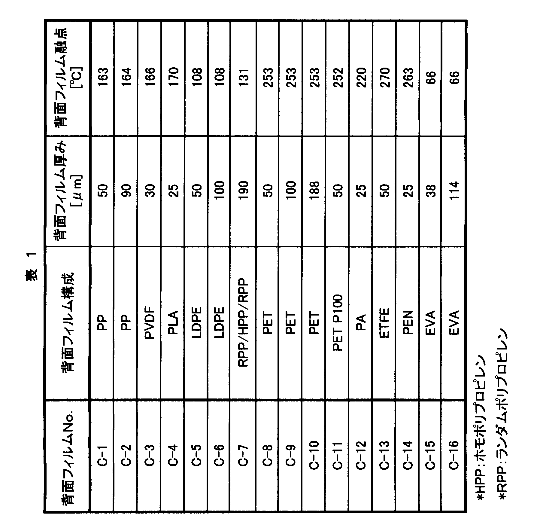


これに対し、防湿フィルムの背面側に融点が特定範囲外であるフィルムを配した比較例1~7については、真空ラミネーション工程における熱処理後の長期防湿性能が著しく低下することが明らかとなった。なお、初期の防湿性能が低い参考例1及び2は防湿性能の劣化度が小さく、実施例との比較から初期防湿性能が高いほど防湿性能の劣化度が大きくなることを示したものである。
このように、本発明における高防湿性太陽電池用表面保護材は、特に防湿性能の劣化が生じやすい高防湿性フィルムにおける防湿性維持の効果を顕著に有していることが明らかとなった。したがって、これを太陽電池用モジュールに用いることにより、太陽電池セルへの湿気の到達や表面保護材自体の劣化を顕著に抑えることができることから太陽電池モジュールの耐久性を顕著に向上させることが可能である。
Claims (15)
- 基材の一方の面に無機薄膜層を有し水蒸気透過率が0.1[g/m2・日]未満である防湿フィルムを有する太陽電池用表面保護材であって、
前記防湿フィルムの無機薄膜層側に耐候性フィルムを有し、かつ
前記防湿フィルムの無機薄膜層と反対側に、融点が80℃以上180℃以下である背面フィルムを有する
ことを特徴とする太陽電池用表面保護材。 - 前記防湿フィルムの水蒸気透過率が0.05[g/m2・日]以下である請求項1に記載の太陽電池用表面保護材。
- 前記防湿フィルムの水蒸気透過率が0.01[g/m2・日]以下である請求項1に記載の太陽電池用表面保護材。
- 前記背面フィルムの融点が130℃以上180℃以下である請求項1~3のいずれかに記載の太陽電池用表面保護材。
- 前記背面フィルムの厚みが25μm以上300μm以下である請求項1~4のいずれかに記載の太陽電池用表面保護材。
- 前記背面フィルムが、ポリエチレン、ポリプロピレン、ポリ乳酸、ポリフッ化ビニル及びポリフッ化ビニリデンから選ばれる少なくとも1種の樹脂を主成分として含む請求項1~5のいずれかに記載の太陽電池用表面保護材。
- 前記背面フィルムが、ポリプロピレンを主成分とし、かつ23℃における弾性率が1000MPa以上、結晶化開始温度が120℃以上であるポリプロピレン系樹脂フィルムである請求項1~5のいずれかに記載の太陽電池用表面保護材。
- 前記背面フィルムが、ポリプロピレンを主成分とし、かつポリプロピレン100質量部に対して0.05質量部以上5.0質量部以下の結晶化核剤を含有するポリプロピレン系樹脂フィルムである請求項1~5及び7のいずれかに記載の太陽電池用表面保護材。
- 前記ポリプロピレンが主にホモポリプロピレンである請求項6~8のいずれかに記載の太陽電池用表面保護材。
- 前記ポリプロピレン系樹脂フィルムが多層からなる請求項7~9のいずれかに記載の太陽電池用表面保護材。
- 前記基材がポリエステル系樹脂フィルムである請求項1~10のいずれかに記載の太陽電池用表面保護材。
- 前記防湿フィルムと前記背面フィルムの間に接着層を有する請求項1~11のいずれかに記載の太陽電池用表面保護材。
- 前記防湿フィルムの無機薄膜層と反対側に前記背面フィルム及びプラスチックフィルムをこの順に有する請求項1~12いずれかに記載の太陽電池用表面保護材。
- 更に封止材を積層して有する請求項1~13のいずれかに記載の太陽電池用表面保護材。
- 請求項1~14のいずれかに記載の太陽電池用表面保護材を用いて作製された太陽電池モジュール。
Priority Applications (4)
| Application Number | Priority Date | Filing Date | Title |
|---|---|---|---|
| EP12741869.7A EP2672525A1 (en) | 2011-01-31 | 2012-01-30 | Surface protective material for solar cell, and solar cell module produced using same |
| US13/982,967 US20140124017A1 (en) | 2011-01-31 | 2012-01-30 | Surface protective material for solar cell, and solar cell module produced using same |
| KR1020137022994A KR20140010058A (ko) | 2011-01-31 | 2012-01-30 | 태양 전지용 표면 보호재 및 그것을 사용하여 제조된 태양 전지 모듈 |
| CN2012800157219A CN103477444A (zh) | 2011-01-31 | 2012-01-30 | 太阳能电池用表面保护材料以及使用该材料制作的太阳能电池组件 |
Applications Claiming Priority (6)
| Application Number | Priority Date | Filing Date | Title |
|---|---|---|---|
| JP2011-018655 | 2011-01-31 | ||
| JP2011018663 | 2011-01-31 | ||
| JP2011-018663 | 2011-01-31 | ||
| JP2011018655 | 2011-01-31 | ||
| JP2011115088A JP2012244068A (ja) | 2011-05-23 | 2011-05-23 | 太陽電池用保護材 |
| JP2011-115088 | 2011-05-23 |
Publications (1)
| Publication Number | Publication Date |
|---|---|
| WO2012105512A1 true WO2012105512A1 (ja) | 2012-08-09 |
Family
ID=46602726
Family Applications (1)
| Application Number | Title | Priority Date | Filing Date |
|---|---|---|---|
| PCT/JP2012/052019 WO2012105512A1 (ja) | 2011-01-31 | 2012-01-30 | 太陽電池用表面保護材及びそれを用いて作製された太陽電池モジュール |
Country Status (6)
| Country | Link |
|---|---|
| US (1) | US20140124017A1 (ja) |
| EP (1) | EP2672525A1 (ja) |
| KR (1) | KR20140010058A (ja) |
| CN (1) | CN103477444A (ja) |
| TW (1) | TW201238060A (ja) |
| WO (1) | WO2012105512A1 (ja) |
Cited By (3)
| Publication number | Priority date | Publication date | Assignee | Title |
|---|---|---|---|---|
| WO2013051403A1 (ja) * | 2011-10-05 | 2013-04-11 | 東レフィルム加工株式会社 | 太陽電池モジュール用裏面保護シートおよびそれを用いた太陽電池モジュール |
| JP2013211391A (ja) * | 2012-03-30 | 2013-10-10 | Dainippon Printing Co Ltd | 太陽電池モジュール用裏面保護シート及び太陽電池モジュール |
| JP2014037127A (ja) * | 2012-08-20 | 2014-02-27 | Mitsubishi Plastics Inc | 積層防湿フィルム |
Families Citing this family (4)
| Publication number | Priority date | Publication date | Assignee | Title |
|---|---|---|---|---|
| WO2017200054A1 (ja) * | 2016-05-20 | 2017-11-23 | 三井化学株式会社 | 硬化性組成物、塗料、太陽電池用塗料、太陽電池バックシート用塗料、接着剤、太陽電池用接着剤、太陽電池バックシート用接着剤、シートの製造方法、および、硬化剤 |
| CN106279904A (zh) * | 2016-08-18 | 2017-01-04 | 苏州度辰新材料有限公司 | 一种挤出型太阳能背板及其制备方法 |
| CN109401059A (zh) * | 2018-11-14 | 2019-03-01 | 安徽兆拓新能源科技有限公司 | 一种太阳能电池封装膜及其制备方法 |
| CN110379629A (zh) * | 2019-06-28 | 2019-10-25 | 淮阴工学院 | 太阳能电池涂层及其在提高染料敏化太阳能电池光电转换效率中的应用 |
Citations (5)
| Publication number | Priority date | Publication date | Assignee | Title |
|---|---|---|---|---|
| JP2009049252A (ja) | 2007-08-22 | 2009-03-05 | Toppan Printing Co Ltd | 太陽電池用部材 |
| JP2009188072A (ja) | 2008-02-05 | 2009-08-20 | Toppan Printing Co Ltd | 積層体および太陽電池用裏面保護シート |
| WO2010104069A1 (ja) * | 2009-03-09 | 2010-09-16 | 積水化学工業株式会社 | 太陽電池用裏面保護シート、太陽電池モジュール及びガスバリアフィルム |
| JP2010272762A (ja) | 2009-05-22 | 2010-12-02 | Dainippon Printing Co Ltd | 太陽電池モジュール用裏面保護シートの製造方法及び当該製造方法で製造された太陽電池モジュール用裏面保護シート |
| JP2010272761A (ja) | 2009-05-22 | 2010-12-02 | Dainippon Printing Co Ltd | 太陽電池モジュール用裏面保護シート |
Family Cites Families (2)
| Publication number | Priority date | Publication date | Assignee | Title |
|---|---|---|---|---|
| EP0854155A4 (en) * | 1996-07-31 | 2002-01-02 | Japan Polyolefins Co Ltd | HIGH CRYSTALLINITY POLYPROPYLENE |
| EP2544896A4 (en) * | 2010-03-12 | 2015-12-02 | Saint Gobain Performance Plast | MULTI-LAYER FILM FOR PHOTOVOLTAIC APPLICATIONS |
-
2012
- 2012-01-30 CN CN2012800157219A patent/CN103477444A/zh active Pending
- 2012-01-30 EP EP12741869.7A patent/EP2672525A1/en not_active Withdrawn
- 2012-01-30 KR KR1020137022994A patent/KR20140010058A/ko not_active Application Discontinuation
- 2012-01-30 WO PCT/JP2012/052019 patent/WO2012105512A1/ja active Application Filing
- 2012-01-30 US US13/982,967 patent/US20140124017A1/en not_active Abandoned
- 2012-01-31 TW TW101103013A patent/TW201238060A/zh unknown
Patent Citations (5)
| Publication number | Priority date | Publication date | Assignee | Title |
|---|---|---|---|---|
| JP2009049252A (ja) | 2007-08-22 | 2009-03-05 | Toppan Printing Co Ltd | 太陽電池用部材 |
| JP2009188072A (ja) | 2008-02-05 | 2009-08-20 | Toppan Printing Co Ltd | 積層体および太陽電池用裏面保護シート |
| WO2010104069A1 (ja) * | 2009-03-09 | 2010-09-16 | 積水化学工業株式会社 | 太陽電池用裏面保護シート、太陽電池モジュール及びガスバリアフィルム |
| JP2010272762A (ja) | 2009-05-22 | 2010-12-02 | Dainippon Printing Co Ltd | 太陽電池モジュール用裏面保護シートの製造方法及び当該製造方法で製造された太陽電池モジュール用裏面保護シート |
| JP2010272761A (ja) | 2009-05-22 | 2010-12-02 | Dainippon Printing Co Ltd | 太陽電池モジュール用裏面保護シート |
Non-Patent Citations (1)
| Title |
|---|
| FUMIO IDE, TOKUSEI BETSU NI WAKARU JITSUYO KOBUNSHI ZAIRYO, 15 March 2002 (2002-03-15), pages 126 - 134, 137 - 138, 142 - 146 * |
Cited By (3)
| Publication number | Priority date | Publication date | Assignee | Title |
|---|---|---|---|---|
| WO2013051403A1 (ja) * | 2011-10-05 | 2013-04-11 | 東レフィルム加工株式会社 | 太陽電池モジュール用裏面保護シートおよびそれを用いた太陽電池モジュール |
| JP2013211391A (ja) * | 2012-03-30 | 2013-10-10 | Dainippon Printing Co Ltd | 太陽電池モジュール用裏面保護シート及び太陽電池モジュール |
| JP2014037127A (ja) * | 2012-08-20 | 2014-02-27 | Mitsubishi Plastics Inc | 積層防湿フィルム |
Also Published As
| Publication number | Publication date |
|---|---|
| TW201238060A (en) | 2012-09-16 |
| US20140124017A1 (en) | 2014-05-08 |
| KR20140010058A (ko) | 2014-01-23 |
| CN103477444A (zh) | 2013-12-25 |
| EP2672525A1 (en) | 2013-12-11 |
Similar Documents
| Publication | Publication Date | Title |
|---|---|---|
| TWI510536B (zh) | 太陽電池用覆蓋薄膜及使用其製作之太陽電池模組 | |
| WO2012105512A1 (ja) | 太陽電池用表面保護材及びそれを用いて作製された太陽電池モジュール | |
| WO2012091122A1 (ja) | 積層防湿フィルム | |
| TW201144333A (en) | Transparent film containing tetrafluoroethylene-hexafluoropropylene copolymer and having an organosilane coupling agent treated surface | |
| JP2012148560A (ja) | 積層防湿フィルム | |
| JP2013211451A (ja) | 太陽電池用封止材・表面保護シート積層体 | |
| JP5830367B2 (ja) | 太陽電池保護用積層体及びそれを用いて作製された太陽電池モジュール | |
| JP2022113709A (ja) | 太陽電池モジュール用の封止材シート及びそれを用いた太陽電池モジュール | |
| WO2013039234A1 (ja) | 太陽電池用保護材 | |
| JP2012213937A (ja) | 積層防湿シート | |
| JP2012148561A (ja) | 積層防湿フィルム | |
| JP2012209375A (ja) | 太陽電池用封止材・表面保護材積層体 | |
| JP2012176608A (ja) | 太陽電池用表面保護材及びそれを用いて作製された太陽電池モジュール | |
| JP2013077818A (ja) | 太陽電池用保護材 | |
| JP2012244068A (ja) | 太陽電池用保護材 | |
| JP2012158154A (ja) | 透明積層防湿フィルム | |
| JP2012213936A (ja) | 積層防湿フィルム | |
| JP6442879B2 (ja) | 積層防湿フィルム | |
| JP6686430B2 (ja) | 太陽電池モジュール用の封止材シート及びそれを用いた太陽電池モジュール | |
| TW201318869A (zh) | 太陽電池用保護材 | |
| JP5474171B1 (ja) | 太陽電池用保護材 | |
| JP5719726B2 (ja) | 太陽電池用前面保護シート及びそれを用いて作製された太陽電池モジュール | |
| JP2012176609A (ja) | 太陽電池用表面保護材及びそれを用いて作製された太陽電池モジュール | |
| WO2014208758A1 (ja) | 太陽電池用保護材 | |
| JP5449312B2 (ja) | 太陽電池用保護材 |
Legal Events
| Date | Code | Title | Description |
|---|---|---|---|
| 121 | Ep: the epo has been informed by wipo that ep was designated in this application |
Ref document number: 12741869 Country of ref document: EP Kind code of ref document: A1 |
|
| NENP | Non-entry into the national phase |
Ref country code: DE |
|
| WWE | Wipo information: entry into national phase |
Ref document number: 2012741869 Country of ref document: EP |
|
| ENP | Entry into the national phase |
Ref document number: 20137022994 Country of ref document: KR Kind code of ref document: A |
|
| WWE | Wipo information: entry into national phase |
Ref document number: 13982967 Country of ref document: US |