WO2012105125A1 - 紙幣取扱装置 - Google Patents
紙幣取扱装置 Download PDFInfo
- Publication number
- WO2012105125A1 WO2012105125A1 PCT/JP2011/078220 JP2011078220W WO2012105125A1 WO 2012105125 A1 WO2012105125 A1 WO 2012105125A1 JP 2011078220 W JP2011078220 W JP 2011078220W WO 2012105125 A1 WO2012105125 A1 WO 2012105125A1
- Authority
- WO
- WIPO (PCT)
- Prior art keywords
- bill
- transport path
- drive motor
- bills
- speed
- Prior art date
- Legal status (The legal status is an assumption and is not a legal conclusion. Google has not performed a legal analysis and makes no representation as to the accuracy of the status listed.)
- Ceased
Links
Images



Classifications
-
- B—PERFORMING OPERATIONS; TRANSPORTING
- B65—CONVEYING; PACKING; STORING; HANDLING THIN OR FILAMENTARY MATERIAL
- B65H—HANDLING THIN OR FILAMENTARY MATERIAL, e.g. SHEETS, WEBS, CABLES
- B65H5/00—Feeding articles separated from piles; Feeding articles to machines
- B65H5/06—Feeding articles separated from piles; Feeding articles to machines by rollers or balls, e.g. between rollers
- B65H5/062—Feeding articles separated from piles; Feeding articles to machines by rollers or balls, e.g. between rollers between rollers or balls
-
- B—PERFORMING OPERATIONS; TRANSPORTING
- B65—CONVEYING; PACKING; STORING; HANDLING THIN OR FILAMENTARY MATERIAL
- B65H—HANDLING THIN OR FILAMENTARY MATERIAL, e.g. SHEETS, WEBS, CABLES
- B65H5/00—Feeding articles separated from piles; Feeding articles to machines
- B65H5/26—Duplicate, alternate, selective, or coacting feeds
-
- B—PERFORMING OPERATIONS; TRANSPORTING
- B65—CONVEYING; PACKING; STORING; HANDLING THIN OR FILAMENTARY MATERIAL
- B65H—HANDLING THIN OR FILAMENTARY MATERIAL, e.g. SHEETS, WEBS, CABLES
- B65H7/00—Controlling article feeding, separating, pile-advancing, or associated apparatus, to take account of incorrect feeding, absence of articles, or presence of faulty articles
-
- G—PHYSICS
- G07—CHECKING-DEVICES
- G07D—HANDLING OF COINS OR VALUABLE PAPERS, e.g. TESTING, SORTING BY DENOMINATIONS, COUNTING, DISPENSING, CHANGING OR DEPOSITING
- G07D11/00—Devices accepting coins; Devices accepting, dispensing, sorting or counting valuable papers
- G07D11/10—Mechanical details
- G07D11/16—Handling of valuable papers
-
- G—PHYSICS
- G07—CHECKING-DEVICES
- G07D—HANDLING OF COINS OR VALUABLE PAPERS, e.g. TESTING, SORTING BY DENOMINATIONS, COUNTING, DISPENSING, CHANGING OR DEPOSITING
- G07D11/00—Devices accepting coins; Devices accepting, dispensing, sorting or counting valuable papers
- G07D11/20—Controlling or monitoring the operation of devices; Data handling
- G07D11/22—Means for sensing or detection
- G07D11/235—Means for sensing or detection for monitoring or indicating operating conditions; for detecting malfunctions
- G07D11/237—Means for sensing or detection for monitoring or indicating operating conditions; for detecting malfunctions for detecting transport malfunctions, e.g. jams or misfeeds
-
- B—PERFORMING OPERATIONS; TRANSPORTING
- B65—CONVEYING; PACKING; STORING; HANDLING THIN OR FILAMENTARY MATERIAL
- B65H—HANDLING THIN OR FILAMENTARY MATERIAL, e.g. SHEETS, WEBS, CABLES
- B65H2301/00—Handling processes for sheets or webs
- B65H2301/40—Type of handling process
- B65H2301/44—Moving, forwarding, guiding material
- B65H2301/447—Moving, forwarding, guiding material transferring material between transport devices
- B65H2301/4474—Pair of cooperating moving elements as rollers, belts forming nip into which material is transported
-
- B—PERFORMING OPERATIONS; TRANSPORTING
- B65—CONVEYING; PACKING; STORING; HANDLING THIN OR FILAMENTARY MATERIAL
- B65H—HANDLING THIN OR FILAMENTARY MATERIAL, e.g. SHEETS, WEBS, CABLES
- B65H2511/00—Dimensions; Position; Numbers; Identification; Occurrences
- B65H2511/20—Location in space
-
- B—PERFORMING OPERATIONS; TRANSPORTING
- B65—CONVEYING; PACKING; STORING; HANDLING THIN OR FILAMENTARY MATERIAL
- B65H—HANDLING THIN OR FILAMENTARY MATERIAL, e.g. SHEETS, WEBS, CABLES
- B65H2513/00—Dynamic entities; Timing aspects
- B65H2513/10—Speed
-
- B—PERFORMING OPERATIONS; TRANSPORTING
- B65—CONVEYING; PACKING; STORING; HANDLING THIN OR FILAMENTARY MATERIAL
- B65H—HANDLING THIN OR FILAMENTARY MATERIAL, e.g. SHEETS, WEBS, CABLES
- B65H2513/00—Dynamic entities; Timing aspects
- B65H2513/20—Acceleration or deceleration
-
- B—PERFORMING OPERATIONS; TRANSPORTING
- B65—CONVEYING; PACKING; STORING; HANDLING THIN OR FILAMENTARY MATERIAL
- B65H—HANDLING THIN OR FILAMENTARY MATERIAL, e.g. SHEETS, WEBS, CABLES
- B65H2513/00—Dynamic entities; Timing aspects
- B65H2513/40—Movement
- B65H2513/42—Route, path
Definitions
- the present invention relates to a bill handling device such as that implemented in an automated teller machine used in a financial institution or the like.
- a bill handling device is mounted on an automated teller machine (ATM) used in financial institutions and the like.
- the bill handling apparatus has a bill receiving / dispensing port having a function of feeding out the bills deposited to the user one by one and a function of releasing the deposited bills, and a bill discriminating portion for discriminating the deposited bills or the dispensed bills.
- the bill discrimination unit discriminates the denomination and the state of the bill, and in order to convey the bill to each appropriate unit, a gate for switching the conveyance destination is installed on the bill conveyance path.
- the discrimination processing time in the bill discrimination portion and the processing time for switching this gate exist.
- the processing time for switching the gate is in time.
- problems such as a collision between a bill and a gate and an error in the transport destination occur. For this reason, usually, the bill delivery interval from each unit is set, and the optimal processing time is secured.
- Patent Document 1 proposes a medium conveyance device which is provided with means for detecting a bill conveyance speed, sets a bill feeding interval based on the detected bill conveyance speed, and constantly maintains an appropriate interval.
- control of the bill dispensing interval is realized by decreasing the bill dispensing speed or increasing the bill dispensing interval, so it is optimal in consideration of the number of processed sheets per unit time. It can not be called control.
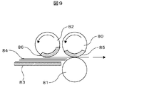
- the pressing plate 83 presses the pickup roller 82 (hereinafter referred to as P roller) to generate a frictional force, and the rubber phase 86 having a high coefficient of friction comes. Pay out the bills.
- the feed roller 80 (hereinafter referred to as F roller) also has a rubber phase 85 having a high friction coefficient in a phase where it is desired to apply a feeding force to the bill, and tries to feed the bill.
- the gate roller 81 (hereinafter referred to as G roller) is configured not to rotate in the delivery direction, and locks the second and subsequent bills.
- one rotation of the F roller 80 causes the bills to be fed out one by one.
- the number of revolutions N of the F roller 80 determines the number of fed sheets per unit time.
- the speed Va of the bill to be fed out is 2 ⁇ ⁇ ⁇ N ⁇ R.
- the speed Va of the bill to be fed out is determined by the number of revolutions N of the F roller 80 and the radius R of the F roller 80. Since the rotation speed N of the F roller 80 is limited by the product specification, the gap L between bills can be increased by increasing the radius R of the F roller 80. However, since the bill handling apparatus is required to be miniaturized, it is difficult to make the F roller 80 large.
- the above-mentioned bill delivery is performed at a connection point between a bill transport path 87a driven by a motor 88a having a function of delivering bills and a bill transport path 87b driven by a motor 88b having a function of connecting units.
- the bill fed at the speed Va by the mechanism is delivered to the bill conveyance path 87b driven at the conveyance speed Vb (Vb> Va) to accelerate the bill. Since the bills themselves do not extend if the transport speed is increased at a fixed number of processed bill per unit time, only the bill interval L can be expanded. That is, in FIG. 10, the relationship of Lb> La is established.
- an object of the present invention is to prevent occurrence of tearing or jamming of a bill in a bill handling device, to improve the conveyance reliability, and to realize high-speed conveyance of a bill.
- the banknote handling apparatus is preferably a banknote handling apparatus for transporting, storing or dispensing banknotes for depositing and dispensing, and for receiving and depositing banknotes for depositing and separating them into the apparatus and for dispensing.
- a drive motor, a storage unit transport path drive motor for driving the storage portion transport path, and the first transport path 3 the first to third drive motor for driving the conveying path each independently, configured as a bill handling apparatus having a control unit for controlling said first to third drive motors in separate speeds.
- the control unit controls the bill handling to control the speed of the first drive motor to be faster than the drive motor for depositing and dispensing port conveyance path and to make the second drive motor faster than the first drive motor. It is configured as a device. In addition, preferably, the control unit performs drive control so that the speed of the third drive motor is higher than the drive motor for the storage portion conveyance path and the speed of the second drive motor is higher than the speed of the third drive motor.
- the first drive motor is configured as the bill handling device controlled at the same speed as the second drive motor.
- the transport path is further divided and driven by an independent drive motor, thereby forming a bill handling device that accelerates in multiple stages.
- the control unit controls the drive motor for the deposit / withdrawal port transport path, the first to third drive motors, and the drive motor for the storage transport path in forward and reverse directions.
- it is configured as a bill handling device for conveying a bill in both directions on each conveyance path.
- the motor of the transport path can be miniaturized.
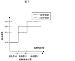
- the side view of the bill handling device used for explanation of payment transaction processing operation by one example.
- the figure which shows the control example of the step acceleration of the banknote in one Example (Example 1).
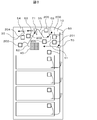
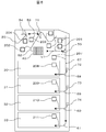
- FIG. 1 is a side view showing the configuration of the bill handling apparatus.
- the bill handling apparatus 1 is for handling and processing bills and is mounted in a case of an automated teller machine (ATM).
- ATM automated teller machine
- the bill deposit / withdrawal port 10 where the user inserts and takes out bills is disposed in the upper front, and a bill discrimination unit that discriminates the authenticity, denomination, and damage state of bills by a sensor or the like in the central portion. 40 are arranged.
- a temporary storage unit 20 for temporarily storing the banknotes deposited by the user until the transaction is established is disposed.
- bill storages 30 to 33 for storing the deposited bills in denominations and feeding them out are arranged.
- These banknote storages may be used as reject storages for storing banknotes that are not suitable for depositing and dispensing transactions, or they can be used to feed out banknotes to be replenished to the banknote storage and store banknotes to be recovered from the banknote storage. It may be used as a loading container.
- the bill transport path 50 of the bill depositing / dispensing port 10 is provided with a bill delivery mechanism for delivering the bill to the bill transport path 51. Further, the bill conveyance path 56 of the bill depositing and dispensing port 10 is provided with a bill storage mechanism for receiving a bill from the bill conveyance path 55.
- the bill transport path 54 of the temporary storage unit 20 includes a bill delivery mechanism and a bill storage mechanism for transferring bills to the bill transport path 53.
- the bill transport paths 58 to 61 of the bill storages 30 to 33 have a bill delivery mechanism and a bill storage mechanism for transferring bills to the bill transport path 57.
- the bill storage and the bill delivery mechanism thereof may be simply referred to as a unit.
- the units are connected by the bill transport paths 50 to 61 and can exchange bills. Distribution of conveyance of bills is performed by switching the bill distribution gates 70 to 74, and the bills are conveyed to a unit which is a desired conveyance destination.
- the direction of the arrows of the bill transport paths 50 to 61 indicates the direction of transporting the bill. When there are arrows at both ends of the transport path, it indicates that the transport path transports the bill in both directions.
- the bill transport paths 50 to 61 are driven and controlled by respective single motors 200 to 211, and when transporting bills from each unit to the bill discriminating portion 40, the speed can be increased in two steps, for example.
- the bill conveyance paths 50 to 61 may be divided into a plurality of bill conveyance paths, and the divided bill conveyance paths may be operated by a motor, respectively, to perform acceleration control in multiple stages.
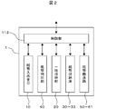
- FIG. 2 is a control block diagram showing control of the bill handling apparatus 1.
- the control unit 112 of the banknote handling apparatus 1 is connected to the main body control unit of the ATM via the control bus, and performs control in accordance with an instruction from the main body control unit. Further, the control unit 112 transmits the state of the banknote handling apparatus 1 to the main control unit, and controls the configuration mechanism unit including each unit according to the transaction process of the banknote handling apparatus 1.
- an actuator such as a drive motor or an electromagnetic solenoid
- the control unit 112 controls the conveyance of the bill by driving the actuator based on the command from the main body control unit or the detection signal of the sensor.
- the control unit 112 variably controls the speed of the drive motor of each bill transport path in multiple stages.
- the bill discrimination unit 40 can perform denomination discrimination and authenticity discrimination of a bill transported in any direction from the front to the back and from the rear to the front on the transport path 51. That is, the bill discrimination unit 40 can discriminate the denomination and the authenticity of the bill transported in both directions, and discriminates whether the bill is rejected or not.
- processing such as deposit transaction, withdrawal transaction, banknote replenishment, banknote recovery, forget-to-get recovery transaction, etc. is executed.
- the deposit transaction process is a process that mainly executes deposit counting process that performs authenticity determination, denomination determination, and counting of the bill inserted into the bill depositing and dispensing port 10.
- the plurality of bills inserted into the bill receiving and dispensing port 10 are fed out to the bill conveying path 51 by the bill feeding mechanism of the bill conveying path 50.
- the first acceleration is performed.
- the bills fed out to the bill conveyance path 51 are delivered to the bill conveyance path 52.
- the second acceleration is performed.
- Vc is set such that Va ⁇ Vc ⁇ Vb holds.
- the current can be reduced even with the same motor to drive with a low torque, and power consumption can be reduced.
- it can be configured by a small motor with low output and low torque, and power consumption can be reduced and the apparatus can be miniaturized.
- the speed Va of the bill fed out at the bill deposit / withdrawal port 10 at the one-step acceleration, the bill discriminating portion 40 As shown in FIG. 6, with respect to the transport speed of the bill transport paths 50, 51, 52 by the drive motors 200 to 202, the speed Va of the bill fed out at the bill deposit / withdrawal port 10 at the one-step acceleration, the bill discriminating portion 40.
- the bill speed Vb (Va ⁇ Vb) when passing through the bill speed Vd fed out at the bill deposit / withdrawal port 10 at the two-step speed increase is Vd ⁇ Va, and Vb-Va> Va-Vd Is set so that Va ⁇ Vc ⁇ Vb is satisfied.
- the radius R of the F roller 80 can be made smaller compared to the one-step acceleration, and the apparatus can be miniaturized.
- the banknote having passed through the banknote discrimination unit 40 is transported by the banknote transport path 52. While the discrimination by the bill discrimination unit 40 is completed during conveyance of the bill conveyance path 52, the bill distribution gate 71 is switched by the control of the control unit 112 according to the discrimination result. As a result of the discrimination, when it is discriminated by the bill discriminating part 40 that the bill can be accepted, the control part 112 switches the bill distributing gate 71 to be connected to the bill conveying path 53 and makes the bill into the conveying paths 53, 54. It is transported and accumulated in the temporary storage unit 20.
- the control unit 112 switches the bill distribution gate 71 to connect to the bill conveyance path 55, and conveys the bill to the conveyance paths 55, 56. Then, it returns to the bill depositing / dispensing port 10 and returns it to the deposit transaction person.
- the bill discrimination unit 40 can discriminate the damage state of the bill, it is possible to change and control the conveyance speed of the bill based on the discrimination result. That is, when the bill is transported to the temporary storage unit 20 or the bill receiving / dispensing port 10 by the bill transport paths 53 to 56, the bill discriminating unit 40 determines that the bill is broken (for example, when the bill is cut) In this case, the control unit 112 prevents the further damage of the bill being conveyed by driving the conveyance motor so as to reduce the conveyance speed of the bill conveyance paths 53 to 56 to such an extent that pulling of the bill due to the speed difference is not strong. be able to. In addition, as a result of the discrimination of the bill state, when it is determined that the bill is in good condition, the control unit 112 controls to accelerate the conveyance speed of the bill conveyance paths 53 to 56 to improve the processing speed. Can.
- the control unit 112 switches the bill distribution gate 71 to connect the bill conveyance path 52 and the bill conveyance path 53, and connects the bill distribution gate 70 to the bill conveyance path 51 and the bill conveyance path 57.
- Switch to The bills delivered to the bill conveyance path 57 are switched to the bill distribution gates 72 to 74 in accordance with the denomination determined by the bill discrimination unit 40, and are stored in any of the bill storages 30 to 33.
- the plurality of bills accumulated in the temporary storage unit 20 are delivered to the bill transport path 53 by the bill delivery mechanism of the bill transport path 54, and then delivered to the bill transport path 52 and pass through the bill discrimination unit 40.
- acceleration is not performed in the transfer of the bill conveyance path 52 and the bill conveyance path 53 in the deposit counting process, but the conveyance speeds of the bill conveyance path 52 and the bill conveyance path 53 are increased to accelerate in the deposit storage process.
- the two-step acceleration is enabled in the bill conveyance path 54, the bill conveyance path 53, and the bill conveyance path 52.
- the bills having passed through the bill discriminating portion 40 are delivered from the bill transport path 52 to the bill transport path 51 and transported so as to be delivered to the bill transport path 57.
- the transfer speed of the bill transfer path 52 is controlled to be faster than the transfer speed of the bill transfer path 51 in the delivery of the bill between the bill transport path 51 and the bill transport path 52. Since it is not necessary to widen the bill interval L by speeding up, this speed increase is not performed. The speed may be increased to improve the storage processing speed.
- the present invention controls an independent drive motor also in other processings from which a bill delivery source, storage destination, conveyance path, and conveyance direction change. It can be realized in the same way.
- the bill conveyance path of the embodiment shown in FIG. 1 may be further divided and operated by an independent motor.
- the bill handling apparatus 1 when used in an area where the state of banknotes in circulation is bad, banknotes due to a rapid speedup can be generated by dividing the banknote transport path 51 and operating with independent motors in the deposit counting process. It is possible to reduce jamming caused by the load on the vehicle.
Landscapes
- Engineering & Computer Science (AREA)
- Mechanical Engineering (AREA)
- Physics & Mathematics (AREA)
- General Physics & Mathematics (AREA)
- Delivering By Means Of Belts And Rollers (AREA)
- Sheets, Magazines, And Separation Thereof (AREA)
- Separation, Sorting, Adjustment, Or Bending Of Sheets To Be Conveyed (AREA)
Abstract
入出金用の紙幣を集積する紙幣入出金口(10)と、紙幣を判別する紙幣判別部(40)と、紙幣を一時集積保管する一時収納部(20)と、紙幣を収納し再分離する紙幣収納部(30~33)と、これらの各部へ紙幣を搬送する紙幣搬送路(50~61)を有する紙幣取扱装置において、各紙幣搬送路はそれぞれ独立したモータで駆動し、各紙幣搬送路における紙幣の搬送速度を段階的に増速制御する。
Description
本発明は、金融機関などで使用される現金自動取引装置に実装されるような紙幣取扱装置に関する。
金融機関などで使用される現金自動取引装置(ATM)には紙幣取扱装置が実装されている。この紙幣取扱装置は、利用者に入金された紙幣を一枚ずつ繰出す機能及び出金紙幣を放出する機能を有する紙幣入出金口と、入金紙幣もしくは出金紙幣を判別する紙幣判別部と、入金した紙幣を一旦収納する一時収納部と、入金紙幣を収納、保管し、出金紙幣として繰出す紙幣収納庫と、紙幣収納庫に収納しない入金紙幣や、紙幣収納庫から繰出された紙幣および入金された紙幣のうち出金しない紙幣を収納するリジェクト庫と、紙幣収納庫に対して補充する紙幣を繰出し紙幣収納庫から回収する紙幣を収納する装填庫と、及びこれらの各ユニットを接続して紙幣を搬送する紙幣搬送路を備えている。
この紙幣取扱装置において、紙幣判別部で金種や紙幣の状態が判別され、それぞれ適当な各ユニットへ紙幣を搬送するために、紙幣搬送路には搬送先を切替えるゲートが設置されている。このとき、紙幣判別部での判別処理時間とこのゲートを切替える処理時間が存在する。ここで、連続して搬送する紙幣の間隔が小さいと、紙幣判別部での判別が終る前に次の紙幣が紙幣判別部に到達して紙幣判別ができなくなり、またゲートを切替える処理時間が間に合わず、紙幣とゲートの衝突や搬送先の間違いといった問題が生じる。このため、通常、各ユニットからの紙幣繰出し間隔を設定し、最適な処理時間を確保している。
しかし、紙幣搬送路のモータにかかる負荷は状況により変化するため、その変化により紙幣搬送速度は変化する。また、紙幣の状態によってもその搬送速度は変化する。このため、各ユニットからの紙幣の繰出し間隔を十分な余裕を持たせて大きくすることにより紙幣の搬送速度の変化に対応している。しかし、この方法は単位時間当たりの処理枚数を低下させることになる。そこで、例えば特許文献1には、紙幣搬送速度を検知する手段を設け、検知した紙幣搬送速度に基づき紙幣繰出し間隔を設定し、常に適切な間隔を維持する媒体搬送装置が提案されている。
特許文献1の技術において、紙幣の繰出し間隔の制御は、紙幣繰出し速度を低下させるかまたは紙幣繰出しを行う間隔を長くすることにより実現しているため、単位時間当たりの処理枚数を考えれば最適な制御とは言えない。
ここで、上記従来の方法とは別の方法として紙幣と紙幣の間隔Lを大きくすることを考える。例えば、図9に示す紙幣繰出し機構において、押圧版83がピックアップローラ82(以下Pローラという)に押し付け摩擦力を発生させて,摩擦係数が高いゴム相86がきたところで、右方(矢印方向)へ紙幣を繰出す。フィードローラ80(以下Fローラという)にも紙幣へ繰出し力を与えたい相で摩擦係数が高いゴム相85があり,紙幣を繰出そうとする。一方、ゲートローラ81(以下Gローラという)は繰出し方向には回転しないように構成され,2枚目以降の紙幣を係止する。この機構により、Fローラ80が一回
転することにより、紙幣が一枚ずつ繰出される。また、Fローラ80の回転数Nは単位時間当たりの繰出枚数を決めるものである。また、Fローラ80の半径Rとする時、繰出す紙幣の速度Vaは2×π×N×Rとなる。
転することにより、紙幣が一枚ずつ繰出される。また、Fローラ80の回転数Nは単位時間当たりの繰出枚数を決めるものである。また、Fローラ80の半径Rとする時、繰出す紙幣の速度Vaは2×π×N×Rとなる。
繰出す紙幣の速度Vaは、前述のように、Fローラ80の回転数NとFローラ80の半径Rにより決定する。Fローラ80の回転数Nは製品仕様により制限されるため、Fローラ80の半径Rを大きくすることにより紙幣と紙幣の間隔Lを大きくすることができる。しかし、紙幣取扱装置には小型化を求められているため、Fローラ80を大きくすることは困難である。
そこで、繰出された紙幣を次の紙幣搬送路との接続箇所で増速することを考える。紙幣取扱装置の多くは、用途やそれに求められる特性の違いなどの理由から、紙幣を繰出す機能を持つ紙幣搬送路を駆動するモータと、各ユニットを接続する紙幣搬送路を駆動するモータとを別にしている。図10に示すように、紙幣を繰出す機能を持つモータ88aにより駆動する紙幣搬送路87aと、ユニットを接続する機能を持つモータ88bにより駆動する紙幣搬送路87bとの接続箇所で、上記紙幣繰出し機構により速度Vaで繰出された紙幣を搬送速度Vb(Vb>Vaとする)で駆動する紙幣搬送路87bに受け渡し、紙幣を増速させる。単位時間当たり一定の紙幣処理枚数において、搬送速度を増速すると紙幣そのものは伸びないので、紙幣間隔Lのみ広げることができる。つまり、図10中においてLb>Laの関係が成り立つ。
しかし、この増速による搬送方法を用いると、増速箇所では紙幣の滑りが発生し、その際、紙幣とベルト間の摩擦力が負荷になるため、紙幣搬送路のモータに十分なトルクが必要となる。一般的にモータは高速域ではトルクが低下するため、トルクを確保し、かつ、増速のための高速化をするためにはモータの大型化や電流の増大化が避けられない。また、増速箇所では紙幣にも負荷が掛かるため、破れを生じたり、ジャムを生じたりする可能性がある。
そこで、本発明の目的は、紙幣取扱装置において紙幣の破れやジャムの発生を防止して搬送信頼性を高め、かつ紙幣の高速搬送を実現することにある。
本発明による紙幣取扱装置は、好ましくは、入出金用の紙幣を搬送して収納又は出金する紙幣取扱装置であって、入金用の紙幣を受入れて装置内へ分離繰出し、かつ出金用に放出される紙幣を集積する紙幣入出金口部と、該紙幣入出金口部から紙幣を分離繰出しする入出金口部搬送路と、出金可能な紙幣を収納する紙幣収納部と、該紙幣収納部に収納された紙幣を分離繰出しする収納部搬送路と、該入出金口部搬送路に接続された第1搬送路と、該第1搬送路に接続された搬送路であって、紙幣を判別する判別部が配置された第2搬送路と、該収納部搬送路と第2搬送路を接続する第3搬送路と、該入出金口部搬送路を駆動する入出金口部搬送路用駆動モータと、該収納部搬送路を駆動する収納部搬送路用駆動モータと、該第1搬送路乃至第3搬送路をそれぞれ独立的に駆動する第1乃至第3駆動モータと、該第1乃至第3駆動モータをそれぞれ別の速度で制御する制御部を有する紙幣取扱装置として構成される。
好ましい例によれば、前記制御部は、入出金口部搬送路用駆動モータよりも第1駆動モータの速度を速く、第1駆動モータよりも第2駆動モータを速くするように制御する紙幣取扱装置として構成される。また、好ましくは、前記制御部は、前記収納部搬送路用駆動モータよりも第3駆動モータの速度を速く、第3駆動モータよりも第2駆動モータの速度を速くするように駆動制御し、第1駆動モータは第2駆動モータと同じ速度で制御する該紙幣取扱装置として構成される。
更に、好ましくは、第1搬送路と第3搬送路において、搬送路をさらに分割して独立な駆動モータにより駆動させることにより、多段階に増速させる紙幣取扱装置として構成される。また、好ましくは、前記制御部は、前記入出金口部搬送路用駆動モータと、前記第1乃至第3駆動モータと、前記収納部搬送路用駆動モータとをそれぞれ正逆方向へ回転制御して、各搬送路上に紙幣を双方向へ搬送する紙幣取扱装置として構成される。
本発明によれば、紙幣の搬送を段階的に増速することにより、各ユニットから繰出された紙幣の増速箇所での紙幣の引っ張りを小さくし、ジャム低減となるため搬送の信頼性を高くすることができる。また、増速箇所で速度差は小さく、大きなトルクを必要としないため搬送路のモータを小型化することができる。
以下、図面を参照して、本発明の一実施形態について説明する。図1は紙幣取扱装置の構成を示す側面図である。紙幣取扱装置1は、紙幣を取扱い処理するもので、現金自動取引装置(ATM)の筐体内に実装される。この紙幣取扱装置1の上部には、主に利用者との紙幣の授受に必要な機構が実装される。即ち、上部前方には利用者が紙幣の投入・取り出しを行う紙幣入出金口10が配置され、中央部にはセンサ等によって紙幣の真偽、金種、および正損状態を判別す
る紙幣判別部40が配置される。また、後部上段には、利用者が入金した紙幣を取引成立までの間一旦収納する一時収納部20が配置される。
る紙幣判別部40が配置される。また、後部上段には、利用者が入金した紙幣を取引成立までの間一旦収納する一時収納部20が配置される。
紙幣取扱装置1の下部には入金された紙幣を金種別に収納し、繰出しするための紙幣収納庫30~33が配置される。これら紙幣収納庫は入金取引や出金取引に適さない紙幣を収納する為のリジェクト庫として用いても良いし、紙幣収納庫に対して補充する紙幣を繰出し、紙幣収納庫から回収する紙幣を収納する装填庫として用いても良い。
紙幣入出金口10の紙幣搬送路50は、紙幣搬送路51へ紙幣を受け渡すための紙幣繰出し機構を備える。また、紙幣入出金口10の紙幣搬送路56は、紙幣搬送路55から紙幣を受け取るための紙幣収納機構を備える。一時収納部20の紙幣搬送路54は紙幣搬送路53へ紙幣を授受するための紙幣繰出し機構と紙幣収納機構を備える。紙幣収納庫30~33の紙幣搬送路58~61は紙幣搬送路57へ紙幣を授受するための紙幣繰出し機構と紙幣収納機構を備える。(なお、紙幣収納庫やそれらの紙幣繰出し機構も含めて、単にユニットということがある。)各ユニットは紙幣搬送路50~61により接続され、紙幣を授受することができる。紙幣の搬送の振り分けは、紙幣振り分けゲート70~74を切替えることにより行われ、所望の搬送先であるユニットへ紙幣を搬送する。ここで、紙幣搬送路50~61の矢印の方向は紙幣を搬送する方向を示す。搬送路の両端に矢印が有る場合は、双方向に紙幣を搬送する搬送路であることを示す。
紙幣搬送路50~61はそれぞれ単独のモータ200~211により駆動制御され、各ユニットから紙幣を紙幣判別部40まで搬送する際に、例えば二段階で増速可能である。なお他の例として、紙幣搬送路50~61を複数の紙幣搬送路に分割し、その分割した紙幣搬送路をそれぞれモータにより動作させ、多段階に増速制御しても良い。
図2は紙幣取扱装置1の制御を示す制御ブロック図である。紙幣取扱装置1の制御部112は、制御バスを介してATMの本体制御部と接続され、本体制御部からの指令に応じて制御を行う。また、制御部112は、紙幣取扱装置1の状態を本体制御部に送信すると共に、紙幣取扱装置1の取引処理に応じて各ユニットを含む構成機構部を制御する。紙幣入出金口10、紙幣判別部40、一時収納部20、紙幣収納庫30~33、紙幣搬送路50~61には、紙幣振り分けゲートを切り替えるアクチュエータ(駆動モータや電磁ソレノイド等)や、紙幣の搬送を監視するセンサが配置されている。制御部112は、本体制御部からの指令やセンサの検知信号に基づいて、アクチュエータを駆動して紙幣を搬送制御する。特に本発明においては、制御部112は、各紙幣搬送路の駆動モータの速度を多段階的に可変制御する。
紙幣判別部40は、搬送路51上の前方から後方および後方から前方の何れの方向へも搬送される紙幣の金種判別および真偽判別を行うことができる。つまり、紙幣判別部40は、双方向に搬送される紙幣を金種判別および真偽判別でき、紙幣をリジェクトか否か判別する。このように構成された紙幣取扱装置1において、入金取引、出金取引、紙幣補充、紙幣回収、取り忘れ回収取引などの処理が実行される。
ここで、紙幣取扱装置1における入金取引処理時の紙幣の搬送制御について説明する。入金取引処理は主に、紙幣入出金口10に投入された紙幣の真偽判別、金種判別、および計数を行う入金計数処理を実行する処理である。
図3を参照するに、紙幣入出金口10に投入された複数枚の紙幣は、紙幣搬送路50の紙幣繰出し機構により紙幣搬送路51へ繰出される。紙幣搬送路51へ紙幣を受け渡すときに、一回目の増速が行われる。紙幣搬送路51へ繰出された紙幣は、紙幣搬送路52へ受け渡される。紙幣搬送路52へ受け渡すときに、二回目の増速が行われる。
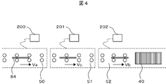
図4に示すように、紙幣搬送路50で繰出す紙幣の速度Va、紙幣判別部40を通過するときの紙幣の速度Vb(Va<Vb)とするとき、紙幣搬送路51での紙幣の速度Vcを図5に示すように、Va<Vc<Vbが成り立つように設定する。このとき、一段階増速と比べ、二段階増速は各増速箇所で速度差は小さくなるため、紙幣の引っ張りを小さくし、ジャム低減となるため搬送信頼性を高める。また、大きなトルクを必要としないため同じモータでも電流を小さくして低いトルクで駆動可能となり消費電力を下げることができる。また小型のトルクの低い小出力のモータで構成することもでき、消費電力を下げると共に装置の小型化を実現できる。
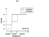
図6に示すように、駆動モータ200~202による紙幣搬送路50,51,52の搬送速度に関して、一段階増速の時の紙幣入出金口10で繰出す紙幣の速度Va、紙幣判別部40を通過するときの紙幣の速度Vb(Va<Vb)とするとき、二段階増速の時の紙幣
入出金口10で繰出す紙幣の速度VdをVd<Va、およびVb-Va>Va-Vdが成り立つように、一回目に増速した紙幣の速度VcをVa<Vc<Vbが成り立つように設定する。この場合、図5に示す例の効果に加え、一段階増速と比べ、二段階増速はFローラ80の半径Rを小さくすることができ、装置の小型化ができる。
入出金口10で繰出す紙幣の速度VdをVd<Va、およびVb-Va>Va-Vdが成り立つように、一回目に増速した紙幣の速度VcをVa<Vc<Vbが成り立つように設定する。この場合、図5に示す例の効果に加え、一段階増速と比べ、二段階増速はFローラ80の半径Rを小さくすることができ、装置の小型化ができる。
更に、図7に示すように、一段階増速の時の紙幣入出金口10で繰出す紙幣の速度Va、紙幣判別部40を通過するときの紙幣の速度Vb(Va<Vb)とするとき、二段階増速の時の紙幣判別部40を通過するときの紙幣の速度VeをVb<Ve、およびVb-Va>Ve-Vbが成り立つように、一回目に増速した紙幣の速度VcをVa<Vc<Vbが成り立つように設定する。この場合、図5に示す例の効果に加え、一段階増速と比べ、二段階増速は単位時間当たりの処理枚数を増加することができ、装置の高速化ができる。
紙幣判別部40を搬送通過する紙幣は、そこで紙幣の真偽、金種、および正損状態が判別される。紙幣判別部40を通過した紙幣は、紙幣搬送路52により搬送される。この紙幣搬送路52を搬送中に紙幣判別部40による判別が完了すると共に、判別結果により制御部112の制御により紙幣振り分けゲート71が切り替えられる。判別の結果、紙幣判別部40によって受入れ可能な紙幣と判別された場合、制御部112は、紙幣振り分けゲート71を紙幣搬送路53に接続するように切り替えて、その紙幣を搬送路53、54に搬送して一時収納部20に集積する。一方、紙幣判別部40によって受け入れ不可能な紙幣と判別された場合、制御部112は、紙幣振り分けゲート71を紙幣搬送路55に接続するように切り替えて、その紙幣を搬送路55、56に搬送して紙幣入出金口10に戻して、入金取引者に返却する。
紙幣判別部40は紙幣の正損状態を判別することができるので、その判別結果に基づいて紙幣の搬送速度を変化させて制御することが可能である。即ち、紙幣搬送路53~56により一時収納部20または紙幣入出金口10に紙幣を搬送するときに、紙幣判別部40によって紙幣が破損している(紙幣が切れている場合など)と判断された場合、制御部112は速度差による紙幣の引っ張りが強くならない程度に紙幣搬送路53~56の搬送速度を減速させるように搬送モータを駆動することで、搬送中の紙幣の更なる破損を防ぐことができる。また、紙幣状態の判別の結果、紙幣の正損状態が良いと判断した場合、制御部112は紙幣搬送路53~56の搬送速度を増速するように制御して、処理速度を向上させることができる。
このようにして紙幣入出金口20に投入された全ての紙幣を処理し、入金された金額と紙幣取扱装置1の計数した金額とが一致し、利用者によって顧客操作部で入金取引確定が入力されると、一時収納部20に一時収納していた紙幣を紙幣収納庫30~33へ収納する収納処理を実行する。
次に、入金収納処理について、図8を用いて説明する。紙幣の収納処理において、制御部112は、紙幣振り分けゲート71を紙幣搬送路52と紙幣搬送路53を接続するように切り替え、紙幣振り分けゲート70を紙幣搬送路51と紙幣搬送路57を接続するように切替える。紙幣搬送路57に受け渡された紙幣は、紙幣判別部40で判別された金種に応じて紙幣振り分けゲート72~74が切替えられて、紙幣収納庫30~33のいずれかに収納される。
ここで、一時収納部20に集積された複数枚の紙幣は、紙幣搬送路54の紙幣繰出し機構により紙幣搬送路53へ繰出し、次に紙幣搬送路52へ受け渡し、紙幣判別部40を通過する。この場合、入金計数処理では紙幣搬送路52と紙幣搬送路53の受け渡しでは増速は行わなかったが、入金収納処理では増速するように、紙幣搬送路52と紙幣搬送路53の搬送速度を設定する。このとき、紙幣搬送路54、紙幣搬送路53、紙幣搬送路52で二段増速を可能とする。
紙幣判別部40を通過した紙幣は、紙幣搬送路52から紙幣搬送路51へ受け渡し、そして紙幣搬送路57へ受け渡すように搬送される。入金計数処理において、紙幣搬送路51と紙幣搬送路52間の紙幣の受け渡しでは、紙幣搬送路52の搬送速度を紙幣搬送路51の搬送速度より速くするように制御したが、入金収納処理では増速することにより紙幣間隔Lを広げる必要が無いため、この増速は行わない。なお、収納処理速度を向上させるため増速しても良い。
以上、入金取引処理時における紙幣の搬送制御について説明したが、本発明は、紙幣の繰出し元、収納先、搬送経路、搬送方向が変わる他の処理においても、独立した駆動モータを制御することで同様に実現できる。
また、図1に示した実施例の紙幣搬送路をさらに区分けして、それぞれ独立したモータにより動作させても良い。例えば、流通している紙幣状態が悪い地域で紙幣取扱装置1を使用する場合、入金計数処理において、紙幣搬送路51を区分けしてそれぞれ独立したモータにより動作させることにより、急な増速による紙幣への負荷が原因となるジャムを低減することができる。
1:紙幣取扱装置、10:入出金口部、20:一時収納部、30~33:紙幣収納庫、40:紙幣判別部、50~61:紙幣搬送路、70~74:紙幣振り分けゲート、200~211:駆動モータ。
Claims (5)
- 入出金用の紙幣を搬送して収納又は出金する紙幣取扱装置であって、
入金用の紙幣を受入れて装置内へ分離繰出し、かつ出金用に放出される紙幣を集積する紙幣入出金口部と、
該紙幣入出金口部から紙幣を分離繰出しする入出金口部搬送路と、
出金可能な紙幣を収納する紙幣収納部と、
該紙幣収納部に収納された紙幣を分離繰出しする収納部搬送路と、
該入出金口部搬送路に接続された第1搬送路と、
該第1搬送路に接続された搬送路であって、紙幣を判別する判別部が配置された第2搬送路と、
該収納部搬送路と第2搬送路を接続する第3搬送路と、
該入出金口部搬送路を駆動する入出金口部搬送路用駆動モータと、
該収納部搬送路を駆動する収納部搬送路用駆動モータと、
該第1搬送路乃至第3搬送路をそれぞれ独立的に駆動する第1乃至第3駆動モータと、
該第1乃至第3駆動モータをそれぞれ別の速度で制御する制御部を有することを特徴とする紙幣取扱装置。 - 前記制御部は、入出金口部搬送路用駆動モータよりも第1駆動モータの速度を速く、第1駆動モータよりも第2駆動モータを速くするように制御することを特徴とする請求項1の紙幣取扱装置。
- 前記制御部は、前記収納部搬送路用駆動モータよりも第3駆動モータの速度を速く、第3駆動モータよりも第2駆動モータの速度を速くするように駆動制御し、第1駆動モータは第2駆動モータと同じ速度で制御することを特徴とする請求項1記載の該紙幣取扱装置。
- 第1搬送路と第3搬送路において、搬送路をさらに分割して独立な駆動モータにより駆動させることにより、多段階に増速させることを特徴とする請求項1記載の該紙幣取扱装置。
- 前記制御部は、前記入出金口部搬送路用駆動モータと、前記第1乃至第3駆動モータと、前記収納部搬送路用駆動モータとをそれぞれ正逆方向へ回転制御して、各搬送路上に紙幣を双方向へ搬送することを特徴とする請求項1乃至4のいずれかの項記載の紙幣取扱装置。
Applications Claiming Priority (2)
| Application Number | Priority Date | Filing Date | Title |
|---|---|---|---|
| JP2011019838A JP5622199B2 (ja) | 2011-02-01 | 2011-02-01 | 紙幣取扱装置 |
| JP2011-019838 | 2011-02-01 |
Publications (1)
| Publication Number | Publication Date |
|---|---|
| WO2012105125A1 true WO2012105125A1 (ja) | 2012-08-09 |
Family
ID=46562704
Family Applications (1)
| Application Number | Title | Priority Date | Filing Date |
|---|---|---|---|
| PCT/JP2011/078220 Ceased WO2012105125A1 (ja) | 2011-02-01 | 2011-12-06 | 紙幣取扱装置 |
Country Status (3)
| Country | Link |
|---|---|
| JP (1) | JP5622199B2 (ja) |
| CN (1) | CN102622806B (ja) |
| WO (1) | WO2012105125A1 (ja) |
Cited By (1)
| Publication number | Priority date | Publication date | Assignee | Title |
|---|---|---|---|---|
| WO2024088481A1 (de) * | 2022-10-28 | 2024-05-02 | Giesecke+Devrient Currency Technology Gmbh | Verfahren und vorrichtung zum transportieren von flächigen elektrodenelementen |
Families Citing this family (9)
| Publication number | Priority date | Publication date | Assignee | Title |
|---|---|---|---|---|
| JP5991902B2 (ja) * | 2012-11-15 | 2016-09-14 | 日立オムロンターミナルソリューションズ株式会社 | 紙葉類搬送装置、及び紙葉類搬送方法 |
| KR101660324B1 (ko) * | 2013-07-31 | 2016-09-29 | 히타치 오므론 터미널 솔루션즈 가부시키가이샤 | 지엽류 처리 장치 |
| CN104134279A (zh) * | 2014-07-28 | 2014-11-05 | 昆山古鳌电子机械有限公司 | 一种具有多次鉴别能力的纸币处理装置 |
| CN104732650B (zh) * | 2015-03-27 | 2017-06-16 | 深圳怡化电脑股份有限公司 | 一种纸币的处理方法及系统 |
| CN105761354A (zh) * | 2015-06-11 | 2016-07-13 | 深圳怡化电脑股份有限公司 | 一种自动存取款机走钞的控制方法 |
| WO2018061130A1 (ja) | 2016-09-28 | 2018-04-05 | 富士通フロンテック株式会社 | 紙葉類取扱装置及び紙葉類取扱方法 |
| CN107424294A (zh) * | 2017-08-21 | 2017-12-01 | 昆山古鳌电子机械有限公司 | 纸币处理装置 |
| JP6956408B2 (ja) * | 2018-01-26 | 2021-11-02 | ローレル精機株式会社 | 紙葉類処理装置 |
| JP7690309B2 (ja) * | 2021-03-31 | 2025-06-10 | 株式会社オリジン | ローラー |
Citations (3)
| Publication number | Priority date | Publication date | Assignee | Title |
|---|---|---|---|---|
| JPH11339087A (ja) * | 1998-05-27 | 1999-12-10 | Mamiya Op Co Ltd | 紙幣収納装置 |
| JP2008152430A (ja) * | 2006-12-15 | 2008-07-03 | Hitachi Omron Terminal Solutions Corp | 紙葉類収納庫および紙葉類取扱装置 |
| JP2009251941A (ja) * | 2008-04-07 | 2009-10-29 | Hitachi Omron Terminal Solutions Corp | 紙葉類搬送装置、および紙幣処理機 |
Family Cites Families (3)
| Publication number | Priority date | Publication date | Assignee | Title |
|---|---|---|---|---|
| JP5042559B2 (ja) * | 2006-08-10 | 2012-10-03 | 日立オムロンターミナルソリューションズ株式会社 | 紙葉類取扱装置 |
| JP5089138B2 (ja) * | 2006-11-09 | 2012-12-05 | 日立オムロンターミナルソリューションズ株式会社 | 紙幣取扱装置 |
| JP5091628B2 (ja) * | 2007-11-07 | 2012-12-05 | 日立オムロンターミナルソリューションズ株式会社 | 紙葉類取扱装置 |
-
2011
- 2011-02-01 JP JP2011019838A patent/JP5622199B2/ja not_active Expired - Fee Related
- 2011-12-06 WO PCT/JP2011/078220 patent/WO2012105125A1/ja not_active Ceased
- 2011-12-19 CN CN201110427568.8A patent/CN102622806B/zh active Active
Patent Citations (3)
| Publication number | Priority date | Publication date | Assignee | Title |
|---|---|---|---|---|
| JPH11339087A (ja) * | 1998-05-27 | 1999-12-10 | Mamiya Op Co Ltd | 紙幣収納装置 |
| JP2008152430A (ja) * | 2006-12-15 | 2008-07-03 | Hitachi Omron Terminal Solutions Corp | 紙葉類収納庫および紙葉類取扱装置 |
| JP2009251941A (ja) * | 2008-04-07 | 2009-10-29 | Hitachi Omron Terminal Solutions Corp | 紙葉類搬送装置、および紙幣処理機 |
Cited By (2)
| Publication number | Priority date | Publication date | Assignee | Title |
|---|---|---|---|---|
| WO2024088481A1 (de) * | 2022-10-28 | 2024-05-02 | Giesecke+Devrient Currency Technology Gmbh | Verfahren und vorrichtung zum transportieren von flächigen elektrodenelementen |
| WO2024088480A1 (de) * | 2022-10-28 | 2024-05-02 | Giesecke+Devrient Currency Technology Gmbh | Verfahren und vorrichtung zum transportieren von wertdokumenten |
Also Published As
| Publication number | Publication date |
|---|---|
| JP5622199B2 (ja) | 2014-11-12 |
| JP2012160067A (ja) | 2012-08-23 |
| CN102622806B (zh) | 2015-09-23 |
| CN102622806A (zh) | 2012-08-01 |
Similar Documents
| Publication | Publication Date | Title |
|---|---|---|
| WO2012105125A1 (ja) | 紙幣取扱装置 | |
| US9183691B2 (en) | Banknote pay-in/pay-out device and banknote processing machine | |
| JP4346474B2 (ja) | 紙幣処理装置 | |
| JP2012221123A (ja) | 紙葉類取扱装置 | |
| JP4804504B2 (ja) | 紙幣入出金装置、現金自動取引装置、および紙幣集積方法 | |
| JP2000187752A (ja) | 紙幣入出金装置 | |
| JP3580468B2 (ja) | 紙幣取引装置 | |
| JP7172237B2 (ja) | 釣銭機 | |
| JP2002312833A (ja) | 貨幣入出金処理システム | |
| JP3766466B2 (ja) | 紙葉類の枚数確定方法及び紙葉類取扱装置 | |
| JP2014241168A (ja) | 紙幣取扱装置 | |
| JP2002312821A (ja) | 紙幣入出金処理システム | |
| KR20200037685A (ko) | 지폐 처리 장치 | |
| JPH0554222A (ja) | 紙幣両替装置 | |
| JP2009151703A (ja) | 紙幣処理装置 | |
| JP2003208654A (ja) | 紙幣入出金機 | |
| JPH1186092A (ja) | 紙葉類搬送装置および自動取引装置 | |
| JP5165196B2 (ja) | 紙幣入出金機 | |
| JP2532668B2 (ja) | 入出金装置 | |
| KR20090008756A (ko) | 금융자동화기기의 스택휠회전제어방법 | |
| JPH02259896A (ja) | 自動現金取引装置 | |
| JP3837233B2 (ja) | 貨幣取扱装置 | |
| JP2661764B2 (ja) | 入出金装置 | |
| JPH0225556B2 (ja) | ||
| JPH11213208A (ja) | 紙幣処理装置 |
Legal Events
| Date | Code | Title | Description |
|---|---|---|---|
| 121 | Ep: the epo has been informed by wipo that ep was designated in this application |
Ref document number: 11857443 Country of ref document: EP Kind code of ref document: A1 |
|
| NENP | Non-entry into the national phase |
Ref country code: DE |
|
| 122 | Ep: pct application non-entry in european phase |
Ref document number: 11857443 Country of ref document: EP Kind code of ref document: A1 |