WO2012102391A1 - 車両の走行支援装置 - Google Patents
車両の走行支援装置 Download PDFInfo
- Publication number
- WO2012102391A1 WO2012102391A1 PCT/JP2012/051871 JP2012051871W WO2012102391A1 WO 2012102391 A1 WO2012102391 A1 WO 2012102391A1 JP 2012051871 W JP2012051871 W JP 2012051871W WO 2012102391 A1 WO2012102391 A1 WO 2012102391A1
- Authority
- WO
- WIPO (PCT)
- Prior art keywords
- vehicle
- image
- processing unit
- braking
- unit
- Prior art date
Links
- 238000003384 imaging method Methods 0.000 claims abstract description 25
- 238000000034 method Methods 0.000 claims abstract description 12
- 230000008569 process Effects 0.000 claims abstract description 10
- 238000004364 calculation method Methods 0.000 claims description 11
- 239000003086 colorant Substances 0.000 claims description 8
- 230000008859 change Effects 0.000 claims description 6
- 230000000295 complement effect Effects 0.000 claims description 6
- 230000008447 perception Effects 0.000 abstract 1
- 230000003287 optical effect Effects 0.000 description 12
- 230000002093 peripheral effect Effects 0.000 description 7
- 238000010586 diagram Methods 0.000 description 6
- 239000003550 marker Substances 0.000 description 4
- 238000001514 detection method Methods 0.000 description 3
- 230000035484 reaction time Effects 0.000 description 2
- 230000007423 decrease Effects 0.000 description 1
- 238000006073 displacement reaction Methods 0.000 description 1
- 230000006870 function Effects 0.000 description 1
- 230000012447 hatching Effects 0.000 description 1
- 238000012986 modification Methods 0.000 description 1
- 230000004048 modification Effects 0.000 description 1
- 230000004044 response Effects 0.000 description 1
Images


Classifications
-
- H—ELECTRICITY
- H04—ELECTRIC COMMUNICATION TECHNIQUE
- H04N—PICTORIAL COMMUNICATION, e.g. TELEVISION
- H04N7/00—Television systems
- H04N7/18—Closed-circuit television [CCTV] systems, i.e. systems in which the video signal is not broadcast
-
- B—PERFORMING OPERATIONS; TRANSPORTING
- B60—VEHICLES IN GENERAL
- B60R—VEHICLES, VEHICLE FITTINGS, OR VEHICLE PARTS, NOT OTHERWISE PROVIDED FOR
- B60R1/00—Optical viewing arrangements; Real-time viewing arrangements for drivers or passengers using optical image capturing systems, e.g. cameras or video systems specially adapted for use in or on vehicles
- B60R1/20—Real-time viewing arrangements for drivers or passengers using optical image capturing systems, e.g. cameras or video systems specially adapted for use in or on vehicles
- B60R1/22—Real-time viewing arrangements for drivers or passengers using optical image capturing systems, e.g. cameras or video systems specially adapted for use in or on vehicles for viewing an area outside the vehicle, e.g. the exterior of the vehicle
- B60R1/23—Real-time viewing arrangements for drivers or passengers using optical image capturing systems, e.g. cameras or video systems specially adapted for use in or on vehicles for viewing an area outside the vehicle, e.g. the exterior of the vehicle with a predetermined field of view
- B60R1/26—Real-time viewing arrangements for drivers or passengers using optical image capturing systems, e.g. cameras or video systems specially adapted for use in or on vehicles for viewing an area outside the vehicle, e.g. the exterior of the vehicle with a predetermined field of view to the rear of the vehicle
-
- B—PERFORMING OPERATIONS; TRANSPORTING
- B62—LAND VEHICLES FOR TRAVELLING OTHERWISE THAN ON RAILS
- B62D—MOTOR VEHICLES; TRAILERS
- B62D15/00—Steering not otherwise provided for
- B62D15/02—Steering position indicators ; Steering position determination; Steering aids
- B62D15/027—Parking aids, e.g. instruction means
- B62D15/0275—Parking aids, e.g. instruction means by overlaying a vehicle path based on present steering angle over an image without processing that image
-
- G—PHYSICS
- G08—SIGNALLING
- G08G—TRAFFIC CONTROL SYSTEMS
- G08G1/00—Traffic control systems for road vehicles
- G08G1/01—Detecting movement of traffic to be counted or controlled
- G08G1/04—Detecting movement of traffic to be counted or controlled using optical or ultrasonic detectors
-
- G—PHYSICS
- G08—SIGNALLING
- G08G—TRAFFIC CONTROL SYSTEMS
- G08G1/00—Traffic control systems for road vehicles
- G08G1/16—Anti-collision systems
- G08G1/168—Driving aids for parking, e.g. acoustic or visual feedback on parking space
-
- H—ELECTRICITY
- H04—ELECTRIC COMMUNICATION TECHNIQUE
- H04N—PICTORIAL COMMUNICATION, e.g. TELEVISION
- H04N13/00—Stereoscopic video systems; Multi-view video systems; Details thereof
- H04N13/20—Image signal generators
- H04N13/204—Image signal generators using stereoscopic image cameras
- H04N13/239—Image signal generators using stereoscopic image cameras using two 2D image sensors having a relative position equal to or related to the interocular distance
-
- H—ELECTRICITY
- H04—ELECTRIC COMMUNICATION TECHNIQUE
- H04N—PICTORIAL COMMUNICATION, e.g. TELEVISION
- H04N13/00—Stereoscopic video systems; Multi-view video systems; Details thereof
- H04N13/30—Image reproducers
- H04N13/398—Synchronisation thereof; Control thereof
-
- H—ELECTRICITY
- H04—ELECTRIC COMMUNICATION TECHNIQUE
- H04N—PICTORIAL COMMUNICATION, e.g. TELEVISION
- H04N7/00—Television systems
- H04N7/18—Closed-circuit television [CCTV] systems, i.e. systems in which the video signal is not broadcast
- H04N7/181—Closed-circuit television [CCTV] systems, i.e. systems in which the video signal is not broadcast for receiving images from a plurality of remote sources
-
- B—PERFORMING OPERATIONS; TRANSPORTING
- B60—VEHICLES IN GENERAL
- B60R—VEHICLES, VEHICLE FITTINGS, OR VEHICLE PARTS, NOT OTHERWISE PROVIDED FOR
- B60R2300/00—Details of viewing arrangements using cameras and displays, specially adapted for use in a vehicle
- B60R2300/30—Details of viewing arrangements using cameras and displays, specially adapted for use in a vehicle characterised by the type of image processing
- B60R2300/302—Details of viewing arrangements using cameras and displays, specially adapted for use in a vehicle characterised by the type of image processing combining image information with GPS information or vehicle data, e.g. vehicle speed, gyro, steering angle data
-
- B—PERFORMING OPERATIONS; TRANSPORTING
- B60—VEHICLES IN GENERAL
- B60T—VEHICLE BRAKE CONTROL SYSTEMS OR PARTS THEREOF; BRAKE CONTROL SYSTEMS OR PARTS THEREOF, IN GENERAL; ARRANGEMENT OF BRAKING ELEMENTS ON VEHICLES IN GENERAL; PORTABLE DEVICES FOR PREVENTING UNWANTED MOVEMENT OF VEHICLES; VEHICLE MODIFICATIONS TO FACILITATE COOLING OF BRAKES
- B60T2201/00—Particular use of vehicle brake systems; Special systems using also the brakes; Special software modules within the brake system controller
- B60T2201/02—Active or adaptive cruise control system; Distance control
- B60T2201/022—Collision avoidance systems
-
- B—PERFORMING OPERATIONS; TRANSPORTING
- B60—VEHICLES IN GENERAL
- B60T—VEHICLE BRAKE CONTROL SYSTEMS OR PARTS THEREOF; BRAKE CONTROL SYSTEMS OR PARTS THEREOF, IN GENERAL; ARRANGEMENT OF BRAKING ELEMENTS ON VEHICLES IN GENERAL; PORTABLE DEVICES FOR PREVENTING UNWANTED MOVEMENT OF VEHICLES; VEHICLE MODIFICATIONS TO FACILITATE COOLING OF BRAKES
- B60T2210/00—Detection or estimation of road or environment conditions; Detection or estimation of road shapes
- B60T2210/30—Environment conditions or position therewithin
- B60T2210/32—Vehicle surroundings
Definitions
- the present invention relates to a device that supports driving of a vehicle. More specifically, the present invention captures a peripheral image of a vehicle and records it on a monitor in the vehicle when traveling such as when parked or temporarily evacuated, for example, when traveling backward.
- the present invention relates to a driving support device for a vehicle that displays and superimposes another image for supporting driving on a surrounding image of the vehicle.
- a travel support device that displays a surrounding image of a vehicle captured by an in-vehicle camera on a monitor installed in the vehicle when the vehicle is parked or temporarily evacuated, for example, when traveling in the back is used. ing. By driving while checking the surrounding image of the vehicle displayed on the in-vehicle monitor, the driver can surely recognize an obstacle and can park in the parking area accurately and easily. Become.
- this driving support device in addition to the surrounding image of the vehicle imaged by the in-vehicle camera, another image for supporting driving is superimposed on the surrounding image of the vehicle.
- a device that displays a vehicle course prediction guide line superimposed on a surrounding image of the vehicle so that the distance and the width between the vehicle and the object can be easily recognized.
- Japanese Patent Application Laid-Open No. 2001-322519 discloses a device that calculates a turning angle of a vehicle from a difference between left and right wheel rotational speeds of the vehicle and displays a guide line superimposed on a monitor according to the turning angle.
- the driver can easily grasp the steering timing, the steering amount, or the reverse amount.
- a marker signal is generated in response to an information signal related to vehicle travel, including the distance between the vehicle and surrounding obstacles, tire steering angle, and travel speed.
- An apparatus for superimposing and displaying on an image is disclosed. In this apparatus, for example, the marker interval is changed according to the traveling speed. Thereby, the distance between vehicles required for safe driving
- Japanese Patent Publication No. 2-36417 the feeling of speed can be grasped to some extent by changing the marker interval according to the traveling speed.
- what is most necessary for safe driving is to call attention to avoid collisions with obstacles.By simply changing the marker interval, it depends largely on the driver's senses and skills, and However, it has been difficult to call attention so as to avoid collision with an obstacle reliably and accurately.
- Japanese Patent Publication No. 2-36417 also discloses mounting a distance sensor, but it is necessary to mount a plurality of sensors in order to cover a wide peripheral area, which increases the cost. .
- An object is to provide a support device.
- a vehicle travel support device is a vehicle travel support device that displays a captured image of a vehicle periphery on an in-vehicle monitor.
- An image processing unit that captures a captured image; an information acquisition unit that acquires speed information of the vehicle; and an image processing unit that processes an image signal of the captured image output from the imaging unit.
- the image related to the braking range corresponding to the speed information of the vehicle is superimposed on the captured image around the vehicle when the vehicle is traveling, any type of image is obtained regardless of the driver's sense and skill.
- the driver can be alerted reliably and accurately to avoid a collision with an obstacle. That is, according to the present invention, the driver can grasp the braking range of the vehicle, so that it is clear at which position the brake can be applied to the obstacle to avoid the collision, and the safety during driving can be improved. It becomes possible.
- the image processing unit may blink the image relating to the braking range. As a result, the driver can easily grasp the braking range of the vehicle.
- the image processing unit may surround the image related to the braking range with a frame line and blink the frame line. Thereby, since only the frame line blinks, the driver can more easily grasp the braking range of the vehicle.
- the image processing unit may display the image related to the braking range using a stripe pattern. Further, the image processing unit displays the image relating to the braking range using a stripe pattern, and the stripe pattern is configured by a first color and a second color which is a complementary color of the first color. May be. Thereby, since the said image is displayed by the complementary color, the braking range of a vehicle can be grasped
- the image processing unit may display the image related to the braking range by a plurality of arrows. Furthermore, the tips of the plurality of arrows may be connected to each other by a line. As a result, the driver can drive while being aware of the traveling direction of the vehicle and the braking range.
- the image processing unit sequentially displays the arrows in the direction of travel from the vehicle side of the in-vehicle monitor. Thereby, the driver can drive while being more aware of the traveling direction.
- the image processing unit may display the image related to the braking range based on the speed information and the idling distance. Thereby, the information regarding the braking range can be accurately presented to the driver.
- the image processing unit further includes a storage unit that stores braking characteristics at the time of actual braking of the vehicle acquired by the information acquisition unit, and the image processing unit stores the speed information of the vehicle acquired by the information acquisition unit and the storage
- a risk region calculation unit that calculates a risk region corresponding to the collision possibility range of the vehicle based on the braking characteristics stored in the unit, and the image superimposing unit captures an image representing the risk region It may be superimposed on the image.
- the braking characteristic at the time of actual braking of the vehicle is stored in the storage unit, and the danger region is calculated based on the vehicle speed information and the braking characteristic in the image processing unit and superimposed on the captured image.
- the driver can accurately grasp the collision possibility range of the vehicle.
- the braking characteristics of the vehicle depend on various conditions such as vehicle weight, road surface condition, driver's braking operation, etc., but in this configuration, the braking characteristics at the time of actual braking of the vehicle are used. Since the above-described various conditions are taken into consideration, it is possible to present a more accurate dangerous area to the driver.
- the image processing unit may display the image related to the braking range based on the braking characteristics and the idling distance. Thereby, the information regarding the braking range can be accurately presented to the driver.
- the braking characteristic may include characteristic information of the speed change of the vehicle with respect to the elapsed time of the brake operation.
- the image processing unit may divide and display an image related to the braking range into a plurality of images according to a requested emergency degree of the brake operation. In this way, by displaying the image related to the braking range according to the emergency degree of the brake operation, information related to the braking range can be presented to the driver in more detail, and the operability during driving can be improved. Is possible.
- the image processing unit may display the plurality of divided images in different colors. As a result, the driver can easily recognize each of the plurality of images.
- the storage unit stores an average value of the back speed of the vehicle acquired by the information acquisition unit, and the image processing unit is based on the back speed of the vehicle acquired by the information acquisition unit and the average value.
- a warning image may be superimposed on the captured image.
- the average value of the back speed is stored, and when the back speed during actual running exceeds the threshold set based on this average value, the warning image is superimposed, so that the driving safety It is possible to further improve the performance.
- the average value of the back speed stored at the time of braking is used for setting the threshold value, it is possible to set an appropriate threshold value for each vehicle and driver.
- the threshold set based on the average value of the back speed is a speed that is higher than the average value and that can ensure safe traveling of the vehicle.
- the vehicle travel support device is configured to acquire an image captured around the vehicle.
- An information acquisition unit that acquires speed information of the vehicle, and an image processing unit that processes an image signal of the captured image, wherein the image processing unit includes the speed information of the vehicle acquired by the information acquisition unit.
- An image superimposing unit that superimposes an image related to the corresponding braking range on the captured image is included. Even in such a configuration, the driver can grasp the braking range of the vehicle, so it is clear at which position braking should be applied to the obstacle to avoid a collision. It becomes possible to improve safety.
- the image related to the braking range corresponding to the speed information of the vehicle is superimposed on the captured image when the vehicle is traveling, it is possible for any driver regardless of the driver's sense and skill. However, it is possible to perform alerting for avoiding a collision with an obstacle reliably and accurately. That is, according to the present invention, the driver can grasp the braking range of the vehicle, so that it is clear at which position the brake can be applied to the obstacle to avoid the collision, and the safety at the time of back travel is improved. Is possible.
- FIG. 1 is a block diagram illustrating a configuration of a vehicle travel support apparatus and peripheral devices thereof according to an embodiment of the present invention. It is a block diagram which shows the specific structure of the image process part in embodiment of this invention. It is a figure which shows an example of a periphery image. It is the figure which superimposed the image showing a dangerous area on the surrounding image, (A) shows the dangerous area display image at the time of low speed, (B) shows the dangerous area display image at the time of high speed. It is a figure which shows the vehicle operation
- FIG. 6 is a diagram in which speed information and a warning image are superimposed on a peripheral image. It is a flowchart which shows the process of the driving assistance device of the vehicle which concerns on embodiment of this invention.
- FIG. 6 is a diagram in which only one of a dangerous area and a quasi-dangerous area is superimposed on a captured image. It is the figure which superimposed the arrow as an image showing a dangerous area on the captured image.
- FIG. 1 is a block diagram showing the configuration of the vehicle back running assist device and its peripheral devices according to the embodiment of the present invention.
- a vehicle back running assist device 1 according to an embodiment of the present invention mainly includes an imaging optical system 2, an imaging unit 3, a memory 4, an image processing unit 5, and a controller unit (information acquisition unit) 6. Have.
- the imaging optical system 2 is an optical member that causes light (that is, a captured image around the vehicle) to enter the imaging unit 3.
- the imaging optical system includes one or a plurality of lenses.
- the lens is preferably a wide-angle lens in order to acquire a wide area image.
- the imaging optical system 2 may include other optical members such as a filter in addition to the lens, and the plurality of optical members are arranged so that their optical axes coincide with each other.
- the imaging unit 3 is mounted on a vehicle and captures a peripheral image of the vehicle, particularly a rear image.
- the imaging unit 3 converts an optical image formed by the imaging optical system 2 into an electrical signal, a CCD sensor, A CMOS sensor or the like is used. Note that an A / D converter (not shown) that converts the analog output of the imaging unit 3 into a digital signal is provided between the imaging unit 3 and the image processing unit 5.
- the memory 4 includes an image memory 42 that stores an image to be superimposed on the captured image output by the imaging unit 3, and a ring buffer memory 41 that stores a vehicle speed history.
- the image processing unit 5 and the controller unit 6 are composed of, for example, an LSI.
- the image processing unit 5 processes the image signal of the captured image output from the imaging unit 3 and outputs the generated image to the display unit 9.
- an in-vehicle monitor is used as the display means 9.
- the controller unit 6 acquires information from various sensors and the like mounted on the vehicle.
- the information acquired here includes, for example, shift position information acquired from the shift position detection sensor 11, brake operation information acquired from the brake pedal sensor 12, vehicle speed information acquired from the vehicle speed sensor 13, and elapsed time acquired from the timer 14. Information etc.
- each sensor is shown here as an example, you may use the other kind of sensor which has the same function.
- a hydraulic pressure sensor that detects brake hydraulic pressure and acquires brake operation information, a brake displacement amount detection sensor, or the like may be used.
- FIG. 2 is a block diagram showing a specific configuration of the image processing unit in the embodiment of the present invention.
- the image processing unit 5 superimposes an image relating to the braking range according to the vehicle speed information acquired by the controller unit 6 on the captured image.
- the image relating to the braking range includes, for example, an image representing a dangerous area and an image representing a semi-dangerous area.
- the image processing unit 5 calculates the danger area corresponding to the collision possibility range of the vehicle based on the vehicle speed information acquired by the controller unit 6 and the braking characteristics stored in the ring buffer memory 41.
- An area calculating unit 51 and an image superimposing unit 55 that superimposes an image representing the dangerous area calculated by the dangerous region calculating unit 51 on the captured image output from the imaging unit 3 and displays the image on the display unit 9 are included.
- the image processing unit 5 may display an image regarding the braking range in accordance with the required emergency degree of the brake operation.
- the image processing unit 5 includes a quasi-dangerous area calculating means 52 in addition to the dangerous area calculating means 51, for example.
- the quasi-dangerous area calculation means 52 calculates a quasi-dangerous area corresponding to the collision possibility range of the vehicle.
- the dangerous area is the area from the time when the driver determines to apply the brake immediately to the time when the driver can stop, that is, the area where the vehicle can stop without colliding with an obstacle if the brake is applied immediately. is there.
- the semi-dangerous area is the area from when the driver decides to apply the brake after a specified number of seconds until the vehicle stops, that is, the vehicle can stop without colliding with an obstacle without applying the brake immediately. This is an area. Even if the dangerous area is braked immediately, the vehicle may collide with an obstacle, or the quasi-dangerous area may be an area close to the limit where the vehicle can stop without colliding with the obstacle. Good. Further, “after the designated second” is set appropriately.
- the dangerous area calculation unit 51 and the quasi-dangerous area calculation unit 52 calculate the dangerous area and the quasi-dangerous area according to at least the vehicle speed information. Therefore, the display range of the dangerous area and the quasi-dangerous area changes according to the speed.
- 20 is a rear image output from the imaging unit 3
- 21 is a superimposed image representing a dangerous area
- 22 is a superimposed image representing a quasi-dangerous area
- 23 is a superimposed image representing a course prediction guide line.
- the length of the traveling direction of the dangerous area and the quasi-dangerous area is short at low speed
- the dangerous area and The quasi-dangerous area is displayed so that the length in the traveling direction becomes longer. This is because the braking distance becomes longer at high speed and the braking distance becomes shorter at low speed.
- the dangerous area and the quasi-dangerous area may be displayed in different colors, and in particular, the colors of each other may be displayed in complementary colors.
- the braking range of the vehicle can be grasped more clearly.
- the information regarding the braking range can be presented to the driver in more detail, and the operability at the time of back travel is improved. It becomes possible.
- the braking characteristic may include a characteristic information of a change in vehicle speed with respect to an elapsed time of the brake operation.
- the vehicle 30 moves forward along a trajectory as shown by a solid line 35 immediately before the back parking, and temporarily stops the vehicle 30 at the back start position.
- FIG. 6 shows the braking characteristics (speed-time graph) immediately before the vehicle 30 stops at the back start position. This indicates that the vehicle travels at a constant speed until the speed reaches zero by stepping on the brake.
- the controller unit 6 When detecting the brake operation signal from the brake pedal sensor 12, the controller unit 6 starts acquiring the vehicle speed information from the vehicle speed sensor 13 and acquires the elapsed time of the brake operation using the timer 14. Then, the speed change of the vehicle with respect to the elapsed time of the brake operation is stored in the ring buffer memory 41. Next, the controller unit 6 acquires current vehicle speed information from the vehicle speed sensor 13 while the vehicle 30 is traveling backward in the parking frame 31 along the locus indicated by the dotted line 36 in FIG. 5. And the braking distance of a vehicle is calculated
- the actual stopping distance may be estimated using the braking distance described above.
- the actual stop distance is obtained by adding an idle running distance that is a distance traveled by the vehicle 30 from when the driver determines to step on the brake to when the driver actually steps on the brake.
- Stop distance braking distance + idle distance
- idle distance [m] reaction time (0.75 [s]) ⁇ vehicle speed [m / s].
- this numerical value is used here as an example, but is not limited to the above.
- the free running distance may not be based on the above formula, and may be set in advance based on a general use situation. An image related to the braking range may be superimposed on the captured image in accordance with the stop distance thus obtained.
- the braking characteristics at the time of actual braking of the vehicle are stored in the ring buffer memory 41, and the danger region is calculated based on the vehicle speed information and the braking characteristics by the image processing unit 5, and the captured image is captured.
- the driver can accurately grasp the collision possibility range of the vehicle.
- the braking characteristics of the vehicle depend on various conditions such as vehicle weight, road surface condition, driver's braking operation, etc., but in this configuration, the braking characteristics at the time of actual braking of the vehicle are used. Since the above-described various conditions are taken into consideration, it is possible to present a more accurate dangerous area to the driver. Therefore, the emergency degree of the brake operation may be determined in consideration of the braking characteristics in addition to the vehicle speed information.
- the braking characteristic of a vehicle is influenced also by the loading condition of a vehicle, you may set by acquiring the information of the loading condition of the said vehicle. Further, a predetermined value may be set in advance as the braking characteristic of the vehicle based on a general use situation.
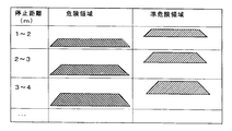
- the image memory 42 may store a table as shown in FIG. 7 set according to the stop distance (or braking distance). This table divides the stop distance in stages, and stores an image representing a dangerous area and an image representing a quasi-dangerous area for each stop distance range. These images are created based on, for example, the design of the imaging optical system such as distortion and angle of view, the mounting conditions of the in-vehicle camera on the vehicle body, and the like.
- a superimposed image different from the image related to the braking range may be displayed.
- the current vehicle speed information 25 acquired from the vehicle speed sensor 13 may be superimposed on the rear image 20.
- the warning image 26 may be superimposed and displayed on the rear image 20 when the speed exceeds a preset designated speed.
- the image processing unit 5 calculates the average value of the vehicle back speed acquired by the controller unit 6 and stores it in the ring buffer memory 41, and the actual back speed calculating means 53.
- Warning display determination means 54 that compares the back speed of the vehicle at the time of braking with a threshold value set based on the average value of the back speed and determines whether or not there is a warning display.
- the warning display determination unit 54 superimposes and displays the warning image 26 on the rear image 20 when the back speed during actual running exceeds a threshold value.
- the threshold set based on the average value of the back speed is a speed that is higher than the average value and that can ensure safe traveling of the vehicle.
- the threshold value is set as an average value + ⁇ , and ⁇ is a predetermined value of 5 km / h or more and 10 km / h or less.
- the threshold value is set as an average value ⁇ ⁇ , and ⁇ is a predetermined value of 1.0 or more and 2.0 or less.
- step S1 the controller unit 6 acquires the position of the shift lever from the shift position detection sensor 11 mounted on the vehicle, and determines whether or not the vehicle is currently traveling backward from the shift position.
- the brake operation information is acquired from the brake pedal sensor 12 in step S2, and it is determined whether or not the brake is applied. If the brake is not applied, the process returns to step S1.
- the speed change (speed history) of the vehicle with respect to the elapsed time of the brake operation is stored in the ring buffer memory 41 in step S3.
- the acquired speed history may be overwritten on the previous speed history and updated.
- step S4 the controller 6 acquires current vehicle speed information from the vehicle speed sensor 13.
- the speed information may be displayed as a numerical value superimposed on the captured image.
- step S5 the dangerous area calculation means 51 calculates the dangerous area based on the current vehicle speed information and the latest speed history stored in the ring buffer memory 41, and corresponds to the table shown in FIG. An image is selected and superimposed on the captured image.
- step S6 the quasi-dangerous area calculation means 52 calculates the quasi-dangerous area based on the current vehicle speed information and the speed history stored in the ring buffer memory 41, and the corresponding is obtained from the table shown in FIG. The image to be selected is selected and superimposed on the captured image.
- step S7 the average value of the back speed is calculated by the back speed average value calculating means 53 and stored in the ring buffer memory 41.
- step S8 the current back speed and the back speed are calculated by the warning display determining means 54. The threshold value set based on the average value is compared. If the current back speed exceeds the threshold value, a warning image is superimposed on the captured image in step S9.
- the driver can grasp the braking range of the vehicle, so it is clear at which position the vehicle can be braked against the obstacle, thereby improving the safety during driving. Is possible.
- the image relating to the braking range includes an image representing the dangerous region and an image representing the quasi-dangerous region.
- the image processing unit may blink only one of the displayed areas, or may blink the surrounding frame line with a frame line.
- the driver can grasp the braking range of the vehicle.
- the image processing unit displays the image using a stripe pattern, or displays the image using a stripe pattern composed of a first color and a second color which is a complementary color of the first color. Also good.
- the display range of the region changes at least according to the vehicle speed information.
- both the image representing the dangerous area and the quasi-dangerous area may be displayed, and only one of the areas may be displayed in various manners as described above.
- the image relating to the braking range may be displayed by a plurality of arrows, and the tips of the plurality of arrows may be connected to each other by lines.
- the course prediction guide line 23 may not be displayed.
- the route prediction guide line By not displaying the route prediction guide line, the area covered by the weight display can be reduced, and the surrounding situation can be confirmed more accurately.
- the shape of the arrow may be sequentially displayed from the vehicle side toward the traveling direction. As a result, the driver can drive while being aware of the traveling direction of the vehicle and the braking range. In this case as well, the display range of the region changes according to at least the vehicle speed information.
- an arrow corresponding to each of the image representing the dangerous area and the quasi-dangerous area is displayed, and the arrow corresponding to each area is displayed in the various manners as described above.
- the arrows corresponding to the dangerous area and the quasi-dangerous area may be displayed in different colors, and in particular, the colors of each other may be displayed in complementary colors.
- the vehicle travel support device includes the imaging unit, but the vehicle travel support device is not limited to the above.
- An image processing unit that processes an image signal of the captured image, and the image processing unit captures an image related to a braking range according to the vehicle speed information acquired by the information acquisition unit. It may include an image superimposing unit to superimpose on. Even in such a configuration, the driver can grasp the braking range of the vehicle, so it is clear at which position braking should be applied to the obstacle to avoid a collision. It becomes possible to improve safety.
- the vehicle travel support device used during back travel is described, but the present invention is not limited to the above. That is, the vehicle travel support device may be used not only when traveling backwards but also when traveling forward.
Abstract
Description
一般的には、車両と対象物との距離や横幅を認識しやすいように、車両の進路予想ガイド線を車両の周辺画像に重畳して表示させる装置が知られている。
また、日本国特公平2-36417号公報には、車両と周辺障害物との距離、タイヤ操舵角、走行速度を含む車両の走行に係る情報信号に応じてマーカー信号を発生し、車両の周辺画像に重畳表示させる装置が開示されている。この装置では、例えば走行速度に応じてマーカー間隔を変化させるようにしている。これにより、安全走行に必要な車間距離を確認することができる。
このように、ブレーキ操作の経過時間に対する車両の速度変化を制動特性として取得することにより、正確な制動特性を容易に取得可能となる。
このように、ブレーキ操作の緊急度合いによって制動範囲に関する画像の区分け表示を行うことにより、運転者に対して制動範囲に関する情報をより詳細に提示することができ、走行時の操作性を向上させることが可能となる。
このように、バック速度の平均値を記憶しておき、実走時のバック速度がこの平均値に基づいて設定されるしきい値を超過する場合に警告画像を重畳させることにより、走行の安全性をより一層高めることが可能となる。また、しきい値の設定において、制動時に記憶したバック速度の平均値を用いる構成としているため、車両および運転者ごとに適切なしきい値を設定することが可能である。なお、バック速度の平均値に基づいて設定されるしきい値とは、平均値より大きい速度で且つ車両の安全走行が確保できる速度である。
このように構成した場合であっても、運転者は車両の制動範囲を把握することができるため、障害物に対してどの位置でブレーキをかければ衝突を回避できるかが明確となり、走行時の安全性を高めることが可能となる。
本発明の実施形態に係る車両のバック走行支援装置1は、主に、撮像光学系2と、撮像部3と、メモリ4と、画像処理部5と、コントローラ部(情報取得部)6とを有する。
撮像部3は、車両に搭載されて前記車両の周辺画像、特に後方画像、を撮像するものであり、撮像光学系2で結像された光学像を電気信号に変換する撮像素子、CCDセンサ、CMOSセンサ等が用いられる。なお、撮像部3と画像処理部5との間には、撮像部3のアナログ出力をデジタル信号に変換するA/D変換器(図示略)を有している。
図1に戻り、画像処理部5とコントローラ部6は、例えばLSIから構成される。
画像処理部5は、撮像部3から出力される撮像画像の画像信号を処理し、生成した画像を表示手段9に出力する。ここで、表示手段9には、例えば車内モニタが用いられる。
コントローラ部6は、車両に搭載される各種センサ等からの情報を取得する。ここで取得する情報は、例えば、シフト位置検出センサ11から取得するシフト位置情報、ブレーキペダルセンサ12から取得するブレーキ操作情報、車速センサ13から取得する車両の速度情報、タイマ14から取得する経過時間情報等である。なお、ここでは一例として、各センサの具体例を示しているが、同様の機能を有する他の種類のセンサを用いてもよい。例えば、ブレーキペダルセンサの代わりに、ブレーキ油圧を検出してブレーキ操作情報を取得する油圧センサやブレーキ変位量検出センサ等を用いてもよい。
また、画像処理部5では、要求されるブレーキ操作の緊急度合いによって制動範囲に関する画像の区分け表示を行うようにしてもよい。この場合、画像処理部5は、例えば危険領域計算手段51のほかに準危険領域計算手段52を含む。準危険領域計算手段52は、車両の衝突可能性範囲に対応した準危険領域を計算するものである。
本実施形態では、危険領域計算手段51および準危険領域計算手段52では、少なくとも車両の速度情報に応じて危険領域および準危険領域を計算している。したがって、速度に応じて危険領域および準危険領域の表示範囲が変わるものである。
図3に示すような後方画像が得られるとき、図4(A)に示すように、低速時においては危険領域および準危険領域の進行方向の長さが短く、高速時においては、危険領域および準危険領域の進行方向の長さが長くなるように表示される。これは、高速時には制動距離が長くなり、低速時には制動距離が短くなるためである。また、危険領域および準危険領域はお互いに異なる色で表示されてもよく、特に、互いの色が補色で表示されてもよい。これにより、車両の制動範囲をより明確に把握する事ができる。
このように、ブレーキ操作の緊急度合いによって制動範囲に関する画像の区分け表示を行うことにより、運転者に対して制動範囲に関する情報をより詳細に提示することができ、バック走行時の操作性を向上させることが可能となる。
次に、車両30が図5の点線36に示す軌跡で駐車枠31内に向かってバック走行している最中に、コントローラ部6は、車速センサ13から現在の車両の速度情報を取得する。そして、図6に示す制動特性を用いて、現在の車両30の速度情報から車両の制動距離を求める。車両30の制動距離は、図6のハッチングで示す面積から求められる。但し、この制動距離は、運転者がすぐにブレーキを踏んでから車両30が停止するまでの距離となる。
停止距離=制動距離+空走距離
一般に、空走距離[m]=反応時間(0.75[s])×車速[m/s]として求めることができる。なお、平均的な人の反応時間は0.75[s]と言われているため、ここでは一例としてこの数値を用いているが、上記に限定されるものではない。また、空走距離は上記の式に基かなくてもよく、一般的な使用状況に基づいて予め設定されてもよい。
このようにして求めた停止距離に応じて、制動範囲に関する画像を撮像画像に重畳表示してもよい。
なお、車両の制動特性は車両の積載状況によっても左右されるため、前記車両の積載状況の情報を取得することで設定されるものであってもよい。また、車両の制動特性は、一般的な使用状況に基づいて、所定値が予め設定されていてもよい。
このテーブルは、停止距離を段階的に分け、停止距離範囲ごとに危険領域を表す画像と準危険領域を表す画像とをそれぞれ格納している。これらの画像は、例えば歪みや画角等の撮像光学系の設計や車載カメラの車体への取り付け条件等に基づいて作成される。
また、予め設定された指定速度以上となったら後方画像20に警告画像26を重畳表示してもよい。この場合、図2に示すように画像処理部5は、コントローラ部6で取得した車両のバック速度の平均値を計算してリングバッファメモリ41に記憶するバック速度平均値計算手段53と、実際の制動時の車両のバック速度と、バック速度の平均値に基づいて設定されるしきい値とを比較して警告表示の有無を判定する警告表示判定手段54とを含む。ここで、警告表示判定手段54は、実走時のバック速度がしきい値を超過した場合に、後方画像20に警告画像26を重畳表示させることが好ましい。
このように、バック速度の平均値を記憶しておき、実走時のバック速度がこの平均値に基づいて設定されるしきい値を超過する場合に警告画像を重畳させることにより、バック走行の安全性をより一層高めることが可能となる。また、しきい値の設定において、実際の制動時に記憶したバック速度の平均値を用いる構成としているため、車両および運転者ごとに適切なしきい値を設定することが可能である。
まず、ステップS1として、コントローラ部6にて、車両に搭載されるシフト位置検出センサ11からシフトレバーの位置を取得し、このシフト位置から車両が現在バック走行中であるか否かを判断する。バック走行中ではないと判断されたとき、ステップS2でブレーキペダルセンサ12からブレーキ操作情報を取得して、ブレーキがかけられているか否かを判断する。ブレーキがかけられていない場合は、ステップS1に戻る。一方、ブレーキがかけられている場合は、ステップS3でブレーキ操作の経過時間に対する車両の速度変化(速度履歴)をリングバッファメモリ41に格納する。ブレーキ操作が行われた後にバック走行せずに前進し、再度ブレーキ操作が行われた場合には、取得した速度履歴を前回の速度履歴に上書きして更新するようにしてもよい。
さらに、ステップS5として、危険領域計算手段51で、現在の車両の速度情報とリングバッファメモリ41に記憶された最新の速度履歴とに基づいて危険領域を計算し、図7に示すテーブルから該当する画像を選択して撮像画像に重畳表示する。
次いで、ステップS7で、バック速度平均値計算手段53にてバック速度の平均値を計算してリングバッファメモリ41に記憶し、ステップS8で、警告表示判定手段54により現在のバック速度とバック速度の平均値に基づいて設定されるしきい値とを比較する。ここで、現在のバック速度がしきい値を超過する場合には、ステップS9で撮像画像に警告画像を重畳表示する。
そして、例えば、前記画像処理部は、表示されたいずれか一方の領域のみを、点滅表示する、もしくは、枠線で囲み枠線を点滅表示してもよい。これにより、運転者は車両の制動範囲を把握することができる。
さらに、前記画像処理部は、ストライプ模様を用いて表示する、もしくは、第1の色と前記第1の色の補色である第2の色によって構成されたストライプ模様を用いて表示するようにしてもよい。これにより、前記画像が異なる色によって表示されているため、車両の制動範囲をより明確に把握する事ができる。これらの場合も、少なくとも車両の速度情報に応じて領域の表示範囲が変わる。
また、危険領域を表す画像と準危険領域の両方を表示し、いずれか一方の領域のみを上記のような種々の様式で表示するように構成してもよい。
この場合も、少なくとも車両の速度情報に応じて領域の表示範囲が変化する。
また、危険領域を表す画像と準危険領域のそれぞれに対応する矢印を表示し、それぞれの領域に対応する矢印を上記のような種々の様式で表示するように構成してもよい。また、危険領域および準危険領域に対応する矢印が互いに異なる色で表示されてもよく、特に、互いの色が補色で表示されてもよい。
このように構成した場合であっても、運転者は車両の制動範囲を把握することができるため、障害物に対してどの位置でブレーキをかければ衝突を回避できるかが明確となり、走行時の安全性を高めることが可能となる。
本出願は、2011年1月27日出願の日本特許出願・出願番号2011-015798、に基づくものであり、その内容はここに参照として取り込まれる。
2撮像光学系
3撮像部
4メモリ
5画像処理部
6コントローラ部
9表示手段
41リングバッファメモリ
42画像メモリ
51危険領域計算手段
52準危険領域計算手段
53バック速度平均値計算手段
54警告表示判定手段
Claims (16)
- 車両周辺の撮像画像を車内モニタ上に表示させる車両の走行支援装置において、
前記車両に搭載されて前記車両周辺の撮像画像を撮像する撮像部と、
前記車両の速度情報を取得する情報取得部と、
前記撮像部から出力される前記撮像画像の画像信号を処理する画像処理部とを有し、
前記画像処理部は、前記情報取得部で取得した前記車両の速度情報に応じた制動範囲に関する画像を前記撮像画像に重畳させる画像重畳部を含む車両の走行支援装置。 - 前記画像処理部は、前記制動範囲に関する前記画像を点滅表示する請求項1に記載の車両の走行支援装置。
- 前記画像処理部は、前記制動範囲に関する前記画像を枠線で囲み、前記枠線を点滅表示する請求項1または2に記載の車両の走行支援装置。
- 前記画像処理部は、前記制動範囲に関する前記画像をストライプ模様を用いて表示する請求項1から3のいずれか一項に記載の車両の走行支援装置。
- 前記ストライプ模様は、第1の色と、前記第1の色の補色である第2の色によって構成される請求項4記載の車両の走行支援装置。
- 前記画像処理部は、前記制動範囲に関する前記画像を複数の矢印によって表示する請求項1に記載の車両の走行支援装置。
- 前記複数の矢印の先端は互いに線で接続されている請求項6に記載の車両の走行支援装置。
- 前記画像処理部は、前記矢印を車内モニタの車両側より進行方向に向かって矢印の形状を順次表示する請求項6または7に記載の車両の走行支援装置。
- 前記画像処理部は、前記速度情報と空走距離に基づいて、前記制動範囲に関する前記画像を表示する請求項1から8のいずれか一項に記載の車両の走行支援装置。
- 前記情報取得部で取得した前記車両の実際の制動時における制動特性を記憶する記憶部をさらに有し、
前記画像処理部は、前記情報取得部で取得した前記車両の速度情報と前記記憶部に記憶された前記制動特性とに基づいて、前記車両の衝突可能性範囲に対応した危険領域を計算する危険領域計算部をさらに含み、前記画像重畳部で前記危険領域を表す画像を前記撮像画像に重畳させる請求項1に記載の車両の走行支援装置。 - 前記制動特性は、ブレーキ操作の経過時間に対する前記車両の速度変化の特性情報を含む請求項10に記載の車両の走行支援装置。
- 前記画像処理部は、前記制動特性と空走距離に基づいて、前記制動範囲に関する前記画像を表示する請求項10に記載の車両の走行支援装置。
- 前記画像処理部では、要求されるブレーキ操作の緊急度合いによって前記制動範囲に関する画像を複数の画像に区分けして表示する請求項1から11のいずれか一項に記載の車両の走行支援装置。
- 前記画像処理部は、前記区分けされた複数の画像をそれぞれ異なる色で表示する請求項10に記載の車両の走行支援装置。
- 前記情報取得部で取得した前記車両のバック速度の平均値を記憶する記憶部を有し、
前記画像処理部では、前記情報取得部で取得した前記車両のバック速度と前記平均値に基づいて設定されるしきい値とを比較して、前記バック速度が前記しきい値を超過する場合に、前記撮像画像に警告画像を重畳させる請求項1から14のいずれか一項に記載の車両の走行支援装置。 - 車両周辺の撮像画像を車内モニタ上に表示させる車両の走行支援装置において、
前記車両周辺の撮像画像を取得する画像取得部と、
前記車両の速度情報を取得する情報取得部と、
前記撮像画像の画像信号を処理する画像処理部とを有し、
前記画像処理部は、前記情報取得部で取得した前記車両の速度情報に応じた制動範囲に関する画像を前記撮像画像に重畳させる画像重畳部を含む車両の走行支援装置。
Priority Applications (2)
| Application Number | Priority Date | Filing Date | Title |
|---|---|---|---|
| JP2012554871A JP5508551B2 (ja) | 2011-01-27 | 2012-01-27 | 車両の走行支援装置 |
| US13/982,247 US9357180B2 (en) | 2011-01-27 | 2012-01-27 | Vehicle driving assist device |
Applications Claiming Priority (2)
| Application Number | Priority Date | Filing Date | Title |
|---|---|---|---|
| JP2011-015798 | 2011-01-27 | ||
| JP2011015798 | 2011-01-27 |
Publications (1)
| Publication Number | Publication Date |
|---|---|
| WO2012102391A1 true WO2012102391A1 (ja) | 2012-08-02 |
Family
ID=46580954
Family Applications (1)
| Application Number | Title | Priority Date | Filing Date |
|---|---|---|---|
| PCT/JP2012/051871 WO2012102391A1 (ja) | 2011-01-27 | 2012-01-27 | 車両の走行支援装置 |
Country Status (3)
| Country | Link |
|---|---|
| US (1) | US9357180B2 (ja) |
| JP (1) | JP5508551B2 (ja) |
| WO (1) | WO2012102391A1 (ja) |
Cited By (5)
| Publication number | Priority date | Publication date | Assignee | Title |
|---|---|---|---|---|
| WO2018037900A1 (ja) * | 2016-08-22 | 2018-03-01 | ソニー株式会社 | 運転支援装置および方法、移動体、並びにプログラム |
| WO2018055842A1 (ja) * | 2016-09-26 | 2018-03-29 | 株式会社Jvcケンウッド | 表示制御装置、表示制御方法及びプログラム |
| JP2018056982A (ja) * | 2016-09-26 | 2018-04-05 | 株式会社Jvcケンウッド | 表示制御装置、表示制御方法及びプログラム |
| JP2020135393A (ja) * | 2019-02-19 | 2020-08-31 | マレリ株式会社 | 運転支援装置 |
| JP2021046079A (ja) * | 2019-09-18 | 2021-03-25 | 株式会社デンソー | 表示制御装置、表示制御方法および表示制御プログラム |
Families Citing this family (9)
| Publication number | Priority date | Publication date | Assignee | Title |
|---|---|---|---|---|
| JP2013224081A (ja) * | 2012-04-20 | 2013-10-31 | Kyocera Corp | 画像処理装置および走行支援方法 |
| KR102622571B1 (ko) * | 2015-02-10 | 2024-01-09 | 모빌아이 비젼 테크놀로지스 엘티디. | 자율 주행을 위한 약도 |
| US9836652B2 (en) * | 2016-02-02 | 2017-12-05 | International Business Machines Corporation | Showing danger areas associated with objects using augmented-reality display techniques |
| JP6616340B2 (ja) * | 2017-01-31 | 2019-12-04 | 矢崎総業株式会社 | 車両用表示装置および車両用表示装置の表示方法 |
| JP6573218B2 (ja) * | 2017-03-31 | 2019-09-11 | マツダ株式会社 | 車両用画像表示装置及び設定方法 |
| JP6439233B2 (ja) * | 2017-03-31 | 2018-12-19 | マツダ株式会社 | 車両用画像表示装置及び画像処理方法 |
| US20220309720A1 (en) * | 2019-12-19 | 2022-09-29 | Gaku Associates Inc. | Boundary line visualization system, boundary line visualization method, boundary line visualization program, and digital photo album creation system |
| CN112896149A (zh) * | 2021-01-23 | 2021-06-04 | 行云智能(深圳)技术有限公司 | 一种基于计算机视觉的自动停车系统 |
| CN116129652B (zh) * | 2023-04-10 | 2023-08-01 | 深圳市城市交通规划设计研究中心股份有限公司 | 单交叉口网联车辆车速引导方法、电子设备及存储介质 |
Citations (5)
| Publication number | Priority date | Publication date | Assignee | Title |
|---|---|---|---|---|
| JP2007141179A (ja) * | 2005-11-22 | 2007-06-07 | Aisin Aw Co Ltd | 車両の運転支援方法及び運転支援装置 |
| JP2008084072A (ja) * | 2006-09-28 | 2008-04-10 | Xanavi Informatics Corp | 停車予測位置を表示するナビゲーション装置 |
| JP2009104543A (ja) * | 2007-10-25 | 2009-05-14 | Sumitomo Electric Ind Ltd | 情報提供装置、コンピュータプログラム及び情報提供方法 |
| JP2009206939A (ja) * | 2008-02-28 | 2009-09-10 | Nissan Motor Co Ltd | 車両用画像表示システム及び画像表示装置並びに画像の強調方法 |
| JP2010028608A (ja) * | 2008-07-23 | 2010-02-04 | Sanyo Electric Co Ltd | 画像処理装置、撮像装置、再生装置及び画像処理方法 |
Family Cites Families (10)
| Publication number | Priority date | Publication date | Assignee | Title |
|---|---|---|---|---|
| JPS59114139A (ja) | 1982-12-17 | 1984-07-02 | Niles Parts Co Ltd | 車両の後方監視モニタ−装置 |
| EP1944222A3 (en) | 2000-05-12 | 2011-11-09 | Kabushiki Kaisha Toyota Jidoshokki | Vehicle backward movement assisting apparatus |
| JP3374833B2 (ja) | 2000-05-12 | 2003-02-10 | 株式会社豊田自動織機 | 駐車時の車両後退支援装置 |
| JP2006309552A (ja) * | 2005-04-28 | 2006-11-09 | Denso Corp | 車両用表示装置 |
| JP4561479B2 (ja) * | 2005-05-26 | 2010-10-13 | アイシン・エィ・ダブリュ株式会社 | 駐車支援方法及び駐車支援装置 |
| JP4274154B2 (ja) * | 2005-05-31 | 2009-06-03 | 富士ゼロックス株式会社 | 立体表示装置 |
| JP2009166691A (ja) * | 2008-01-16 | 2009-07-30 | Mazda Motor Corp | 車両の走行制御装置 |
| US9789812B2 (en) * | 2009-08-03 | 2017-10-17 | Apu Mullick | Forward warning system for motor vehicles |
| CA2712576C (en) * | 2009-08-11 | 2012-04-10 | Certusview Technologies, Llc | Systems and methods for complex event processing of vehicle-related information |
| JP5251947B2 (ja) * | 2010-09-17 | 2013-07-31 | 日産自動車株式会社 | 車両用画像表示装置 |
-
2012
- 2012-01-27 WO PCT/JP2012/051871 patent/WO2012102391A1/ja active Application Filing
- 2012-01-27 US US13/982,247 patent/US9357180B2/en active Active
- 2012-01-27 JP JP2012554871A patent/JP5508551B2/ja not_active Expired - Fee Related
Patent Citations (5)
| Publication number | Priority date | Publication date | Assignee | Title |
|---|---|---|---|---|
| JP2007141179A (ja) * | 2005-11-22 | 2007-06-07 | Aisin Aw Co Ltd | 車両の運転支援方法及び運転支援装置 |
| JP2008084072A (ja) * | 2006-09-28 | 2008-04-10 | Xanavi Informatics Corp | 停車予測位置を表示するナビゲーション装置 |
| JP2009104543A (ja) * | 2007-10-25 | 2009-05-14 | Sumitomo Electric Ind Ltd | 情報提供装置、コンピュータプログラム及び情報提供方法 |
| JP2009206939A (ja) * | 2008-02-28 | 2009-09-10 | Nissan Motor Co Ltd | 車両用画像表示システム及び画像表示装置並びに画像の強調方法 |
| JP2010028608A (ja) * | 2008-07-23 | 2010-02-04 | Sanyo Electric Co Ltd | 画像処理装置、撮像装置、再生装置及び画像処理方法 |
Cited By (8)
| Publication number | Priority date | Publication date | Assignee | Title |
|---|---|---|---|---|
| WO2018037900A1 (ja) * | 2016-08-22 | 2018-03-01 | ソニー株式会社 | 運転支援装置および方法、移動体、並びにプログラム |
| JPWO2018037900A1 (ja) * | 2016-08-22 | 2019-06-20 | ソニー株式会社 | 運転支援装置および方法、移動体、並びにプログラム |
| US11167752B2 (en) | 2016-08-22 | 2021-11-09 | Sony Corporation | Driving assistant apparatus, driving assistant method, moving object, and program |
| WO2018055842A1 (ja) * | 2016-09-26 | 2018-03-29 | 株式会社Jvcケンウッド | 表示制御装置、表示制御方法及びプログラム |
| JP2018056982A (ja) * | 2016-09-26 | 2018-04-05 | 株式会社Jvcケンウッド | 表示制御装置、表示制御方法及びプログラム |
| JP2020135393A (ja) * | 2019-02-19 | 2020-08-31 | マレリ株式会社 | 運転支援装置 |
| JP2021046079A (ja) * | 2019-09-18 | 2021-03-25 | 株式会社デンソー | 表示制御装置、表示制御方法および表示制御プログラム |
| JP7200891B2 (ja) | 2019-09-18 | 2023-01-10 | 株式会社デンソー | 表示制御装置、表示制御方法および表示制御プログラム |
Also Published As
| Publication number | Publication date |
|---|---|
| US9357180B2 (en) | 2016-05-31 |
| JPWO2012102391A1 (ja) | 2014-07-03 |
| US20130307986A1 (en) | 2013-11-21 |
| JP5508551B2 (ja) | 2014-06-04 |
Similar Documents
| Publication | Publication Date | Title |
|---|---|---|
| JP5508551B2 (ja) | 車両の走行支援装置 | |
| JP5440867B2 (ja) | 駐車支援装置 | |
| US20200086793A1 (en) | Periphery monitoring device | |
| US8793053B2 (en) | Vehicle periphery monitoring device | |
| US10913496B2 (en) | Parking assistance device | |
| EP2990265B1 (en) | Vehicle control apparatus | |
| EP1591315B1 (en) | Parking assist apparatus for vehicle | |
| CN104136282B (zh) | 行驶控制装置以及行驶控制方法 | |
| JP2003146133A (ja) | 車両用周辺監視装置 | |
| JP2011151479A5 (ja) | ||
| JP2012056428A (ja) | 運転支援装置 | |
| JP5169912B2 (ja) | 駐車支援装置 | |
| JP6549958B2 (ja) | 自動運転装置 | |
| JP4962176B2 (ja) | 走行軌跡表示装置 | |
| JP2017065357A (ja) | 危険度算出装置 | |
| CN111201160A (zh) | 牵引辅助装置 | |
| JP2007142765A (ja) | 車両周辺監視装置 | |
| JP2012147285A (ja) | バックモニタ装置 | |
| WO2018025441A1 (ja) | 周辺監視装置 | |
| US10875577B2 (en) | Traction assist apparatus | |
| JP2007098979A (ja) | 駐車支援装置 | |
| JP7452479B2 (ja) | 表示制御装置 | |
| JP2019046086A (ja) | 周辺監視装置 | |
| JP6704645B2 (ja) | 車両用表示システム | |
| JP2024005308A (ja) | 駐車支援装置 |
Legal Events
| Date | Code | Title | Description |
|---|---|---|---|
| 121 | Ep: the epo has been informed by wipo that ep was designated in this application |
Ref document number: 12739455 Country of ref document: EP Kind code of ref document: A1 |
|
| ENP | Entry into the national phase |
Ref document number: 2012554871 Country of ref document: JP Kind code of ref document: A |
|
| WWE | Wipo information: entry into national phase |
Ref document number: 13982247 Country of ref document: US |
|
| NENP | Non-entry into the national phase |
Ref country code: DE |
|
| 122 | Ep: pct application non-entry in european phase |
Ref document number: 12739455 Country of ref document: EP Kind code of ref document: A1 |