WO2012102346A1 - Cu-In-Ga-Se太陽電池用ガラス基板およびそれを用いた太陽電池 - Google Patents
Cu-In-Ga-Se太陽電池用ガラス基板およびそれを用いた太陽電池 Download PDFInfo
- Publication number
- WO2012102346A1 WO2012102346A1 PCT/JP2012/051693 JP2012051693W WO2012102346A1 WO 2012102346 A1 WO2012102346 A1 WO 2012102346A1 JP 2012051693 W JP2012051693 W JP 2012051693W WO 2012102346 A1 WO2012102346 A1 WO 2012102346A1
- Authority
- WO
- WIPO (PCT)
- Prior art keywords
- glass substrate
- glass
- less
- solar cell
- temperature
- Prior art date
- Legal status (The legal status is an assumption and is not a legal conclusion. Google has not performed a legal analysis and makes no representation as to the accuracy of the status listed.)
- Ceased
Links
Images

Classifications
-
- H—ELECTRICITY
- H10—SEMICONDUCTOR DEVICES; ELECTRIC SOLID-STATE DEVICES NOT OTHERWISE PROVIDED FOR
- H10F—INORGANIC SEMICONDUCTOR DEVICES SENSITIVE TO INFRARED RADIATION, LIGHT, ELECTROMAGNETIC RADIATION OF SHORTER WAVELENGTH OR CORPUSCULAR RADIATION
- H10F77/00—Constructional details of devices covered by this subclass
- H10F77/10—Semiconductor bodies
- H10F77/16—Material structures, e.g. crystalline structures, film structures or crystal plane orientations
- H10F77/169—Thin semiconductor films on metallic or insulating substrates
- H10F77/1694—Thin semiconductor films on metallic or insulating substrates the films including Group I-III-VI materials, e.g. CIS or CIGS
-
- C—CHEMISTRY; METALLURGY
- C03—GLASS; MINERAL OR SLAG WOOL
- C03C—CHEMICAL COMPOSITION OF GLASSES, GLAZES OR VITREOUS ENAMELS; SURFACE TREATMENT OF GLASS; SURFACE TREATMENT OF FIBRES OR FILAMENTS MADE FROM GLASS, MINERALS OR SLAGS; JOINING GLASS TO GLASS OR OTHER MATERIALS
- C03C3/00—Glass compositions
- C03C3/04—Glass compositions containing silica
- C03C3/076—Glass compositions containing silica with 40% to 90% silica, by weight
- C03C3/083—Glass compositions containing silica with 40% to 90% silica, by weight containing aluminium oxide or an iron compound
- C03C3/085—Glass compositions containing silica with 40% to 90% silica, by weight containing aluminium oxide or an iron compound containing an oxide of a divalent metal
- C03C3/087—Glass compositions containing silica with 40% to 90% silica, by weight containing aluminium oxide or an iron compound containing an oxide of a divalent metal containing calcium oxide, e.g. common sheet or container glass
-
- C—CHEMISTRY; METALLURGY
- C03—GLASS; MINERAL OR SLAG WOOL
- C03C—CHEMICAL COMPOSITION OF GLASSES, GLAZES OR VITREOUS ENAMELS; SURFACE TREATMENT OF GLASS; SURFACE TREATMENT OF FIBRES OR FILAMENTS MADE FROM GLASS, MINERALS OR SLAGS; JOINING GLASS TO GLASS OR OTHER MATERIALS
- C03C3/00—Glass compositions
- C03C3/04—Glass compositions containing silica
- C03C3/076—Glass compositions containing silica with 40% to 90% silica, by weight
- C03C3/089—Glass compositions containing silica with 40% to 90% silica, by weight containing boron
- C03C3/091—Glass compositions containing silica with 40% to 90% silica, by weight containing boron containing aluminium
-
- C—CHEMISTRY; METALLURGY
- C03—GLASS; MINERAL OR SLAG WOOL
- C03C—CHEMICAL COMPOSITION OF GLASSES, GLAZES OR VITREOUS ENAMELS; SURFACE TREATMENT OF GLASS; SURFACE TREATMENT OF FIBRES OR FILAMENTS MADE FROM GLASS, MINERALS OR SLAGS; JOINING GLASS TO GLASS OR OTHER MATERIALS
- C03C3/00—Glass compositions
- C03C3/04—Glass compositions containing silica
- C03C3/076—Glass compositions containing silica with 40% to 90% silica, by weight
- C03C3/089—Glass compositions containing silica with 40% to 90% silica, by weight containing boron
- C03C3/091—Glass compositions containing silica with 40% to 90% silica, by weight containing boron containing aluminium
- C03C3/093—Glass compositions containing silica with 40% to 90% silica, by weight containing boron containing aluminium containing zinc or zirconium
-
- H—ELECTRICITY
- H10—SEMICONDUCTOR DEVICES; ELECTRIC SOLID-STATE DEVICES NOT OTHERWISE PROVIDED FOR
- H10F—INORGANIC SEMICONDUCTOR DEVICES SENSITIVE TO INFRARED RADIATION, LIGHT, ELECTROMAGNETIC RADIATION OF SHORTER WAVELENGTH OR CORPUSCULAR RADIATION
- H10F10/00—Individual photovoltaic cells, e.g. solar cells
- H10F10/10—Individual photovoltaic cells, e.g. solar cells having potential barriers
- H10F10/16—Photovoltaic cells having only PN heterojunction potential barriers
- H10F10/167—Photovoltaic cells having only PN heterojunction potential barriers comprising Group I-III-VI materials, e.g. CdS/CuInSe2 [CIS] heterojunction photovoltaic cells
-
- H—ELECTRICITY
- H10—SEMICONDUCTOR DEVICES; ELECTRIC SOLID-STATE DEVICES NOT OTHERWISE PROVIDED FOR
- H10F—INORGANIC SEMICONDUCTOR DEVICES SENSITIVE TO INFRARED RADIATION, LIGHT, ELECTROMAGNETIC RADIATION OF SHORTER WAVELENGTH OR CORPUSCULAR RADIATION
- H10F19/00—Integrated devices, or assemblies of multiple devices, comprising at least one photovoltaic cell covered by group H10F10/00, e.g. photovoltaic modules
- H10F19/80—Encapsulations or containers for integrated devices, or assemblies of multiple devices, having photovoltaic cells
- H10F19/807—Double-glass encapsulation, e.g. photovoltaic cells arranged between front and rear glass sheets
-
- H—ELECTRICITY
- H10—SEMICONDUCTOR DEVICES; ELECTRIC SOLID-STATE DEVICES NOT OTHERWISE PROVIDED FOR
- H10F—INORGANIC SEMICONDUCTOR DEVICES SENSITIVE TO INFRARED RADIATION, LIGHT, ELECTROMAGNETIC RADIATION OF SHORTER WAVELENGTH OR CORPUSCULAR RADIATION
- H10F77/00—Constructional details of devices covered by this subclass
- H10F77/10—Semiconductor bodies
- H10F77/12—Active materials
- H10F77/126—Active materials comprising only Group I-III-VI chalcopyrite materials, e.g. CuInSe2, CuGaSe2 or CuInGaSe2 [CIGS]
-
- Y—GENERAL TAGGING OF NEW TECHNOLOGICAL DEVELOPMENTS; GENERAL TAGGING OF CROSS-SECTIONAL TECHNOLOGIES SPANNING OVER SEVERAL SECTIONS OF THE IPC; TECHNICAL SUBJECTS COVERED BY FORMER USPC CROSS-REFERENCE ART COLLECTIONS [XRACs] AND DIGESTS
- Y02—TECHNOLOGIES OR APPLICATIONS FOR MITIGATION OR ADAPTATION AGAINST CLIMATE CHANGE
- Y02E—REDUCTION OF GREENHOUSE GAS [GHG] EMISSIONS, RELATED TO ENERGY GENERATION, TRANSMISSION OR DISTRIBUTION
- Y02E10/00—Energy generation through renewable energy sources
- Y02E10/50—Photovoltaic [PV] energy
- Y02E10/541—CuInSe2 material PV cells
Definitions
- Group 11-13, 11-16 compound semiconductors having a chalcopyrite crystal structure and cubic or hexagonal 12-16 group compound semiconductors have a large absorption coefficient for light in the visible to near-infrared wavelength range. have. Therefore, it is expected as a material for high-efficiency thin film solar cells.
- Typical examples include Cu (In, Ga) Se 2 (hereinafter referred to as “CIGS” or “Cu—In—Ga—Se”) and CdTe.
- the present invention is a Cu- having a good balance of high power generation efficiency, high glass transition temperature, predetermined average thermal expansion coefficient, high glass strength, low glass density, solubility during sheet glass production, formability, and devitrification prevention. It is an object to provide a glass substrate for an In—Ga—Se solar cell and a solar cell using the same.
- the average coefficient of thermal expansion at 50 to 350 ° C. is 70 ⁇ 10 ⁇ 7 to 85 ⁇ 10 ⁇ 7 / ° C.
- the temperature (T 4 ) at which the viscosity is 10 4 dPa ⁇ s is 1220 ° C.
- the temperature (T 2 ) at which the viscosity becomes 10 2 dPa ⁇ s is 1630 ° C. or less
- the relationship between the T 4 and the devitrification temperature (T L ) is T 4 ⁇ T L ⁇ ⁇ 20 ° C.
- the density is 2.
- the glass substrate for a Cu—In—Ga—Se solar cell according to the above (1) which is 65 g / cm 3 or less.
- the glass substrate for a Cu—In—Ga—Se solar cell of the present invention has high power generation efficiency, high glass transition temperature, predetermined average thermal expansion coefficient, high glass strength, low glass density, solubility during production of sheet glass, molding Property and anti-devitrification property can be balanced.
- a solar cell with high power generation efficiency can be provided.
- the average thermal expansion coefficient at 50 to 350 ° C. is 70 ⁇ 10 ⁇ 7 to 90 ⁇ 10 ⁇ 7 / ° C.
- the temperature (T 4 ) at which the viscosity is 10 4 dPa ⁇ s is 1230 ° C.
- the temperature (T 2 ) at which the viscosity becomes 10 2 dPa ⁇ s is 1650 ° C. or less
- the relationship between the T 4 and the devitrification temperature (T L ) is T 4 ⁇ T L ⁇ ⁇ 30 ° C.
- the density is 2.
- This is a glass substrate for a Cu—In—Ga—Se solar cell, which is 7 g / cm 3 or less.
- Cu—In—Ga—Se is hereinafter referred to as “CIGS”.
- the glass transition temperature (T g ) of the glass substrate for CIGS solar cell of the present invention is 640 ° C. or higher, which is higher than the glass transition temperature of soda lime glass.
- the glass transition temperature (T g ) is preferably 645 ° C. or higher, more preferably 650 ° C. or higher, and further preferably 655 ° C. or higher in order to ensure the formation of the CIGS layer at a high temperature.
- the average thermal expansion coefficient at 50 to 350 ° C. of the glass substrate for CIGS solar cell of the present invention is 70 ⁇ 10 ⁇ 7 to 90 ⁇ 10 ⁇ 7 / ° C. If it is less than 70 ⁇ 10 ⁇ 7 / ° C. or more than 90 ⁇ 10 ⁇ 7 / ° C., the difference in thermal expansion from the CIGS layer becomes too large, and defects such as peeling easily occur. Preferably, it is 85 ⁇ 10 ⁇ 7 / ° C. or less.
- the relationship between the temperature (T 4 ) at which the viscosity is 10 4 dPa ⁇ s and the devitrification temperature (T L ) is T 4 ⁇ T L ⁇ ⁇ 30 ° C.
- T 4 The -T L is lower than -30 ° C., devitrification is likely to occur at the time of sheet glass forming, there is a possibility that the molding of the glass plate becomes difficult.
- T 4 -T L is preferably -20 ° C. or higher, more preferably -10 ° C. or higher, more preferably 0 °C or more, particularly preferably 10 ° C. or higher.
- the devitrification temperature refers to the maximum temperature at which crystals are not generated on the glass surface and inside when the glass is held at a specific temperature for 17 hours.
- T 4 is 1230 ° C. or less.
- T 4 is preferably 1220 ° C. or lower, and more preferably 1210 ° C. or lower.
- the glass substrate for CIGS solar cell of the present invention has a temperature (T 2 ) at which the viscosity becomes 10 2 dPa ⁇ s at 1650 ° C. or less in consideration of glass solubility, that is, improvement in homogeneity and productivity.
- T 2 are preferably 1630 ° C. or less, more preferably 1620 ° C. or less.
- the specific elastic modulus is usually 37.5 GPa ⁇ cm 3 / g or less, considering that the glass composition range can be easily produced when a glass substrate is produced by a usual method such as a float method or a fusion method. It is.
- the specific elastic modulus (E / d) may be within the ranges specified in the present application.
- the CIGS solar cell glass substrate of the present invention preferably has a density of 2.7 g / cm 3 or less. When the density exceeds 2.7 g / cm 3 , the product mass becomes heavy, which is not preferable.
- the density is more preferably 2.65 g / cm 3 or less, and still more preferably 2.6 g / cm 3 or less.
- the density is usually 2.4 g / cm 3 or more in consideration of the glass composition range that can be easily produced when a glass substrate is produced by a usual method such as a float method or a fusion method.
- the glass substrate for CIGS solar cell of the present invention preferably has a brittleness index value of less than 7000 m ⁇ 1/2 . If the brittleness index value is 7000 m ⁇ 1/2 or more, the glass substrate tends to break during the production process of the solar cell, which is not preferable. It is more preferably 6900 m ⁇ 1/2 or less, and further preferably 6800 m ⁇ 1/2 or less.
- the brittleness index value of the glass substrate is obtained as “B” defined by the following formula (1) (J. Seghal, et al., J. Mat. Sci. Lett., 14). 167 (1995)).
- c / a 0.0056B 2/3 P 1/6 (1)
- P is the indentation load of the Vickers indenter
- a and c are the diagonal length of the Vickers indentation and the length of the crack generated from the four corners (the total length of two symmetrical cracks including the indentation).
- the brittleness index value B is calculated using the dimensions of the Vickers indentation driven on the surface of various glass substrates and Equation (1).
- CaO It can be contained because it has the effect of lowering the viscosity at the time of melting the glass and promoting the melting. Preferably it is 1% or more, More preferably, it is 1.5% or more, More preferably, it is 2% or more. However, if it exceeds 6.5%, the average thermal expansion coefficient of the glass substrate at 50 to 350 ° C. may increase. Moreover, there is a possibility that sodium is difficult to move in the glass substrate and power generation efficiency is lowered. Preferably it is 6% or less.
- SrO It can be contained because it has the effect of reducing the viscosity at the time of melting the glass and promoting the melting. However, if it exceeds 3%, the power generation efficiency decreases, the average thermal expansion coefficient of the glass substrate at 50 to 350 ° C. increases, the density increases, and the brittleness index value described later may increase. It is preferably 2.5% or less, and more preferably 2% or less.
- BaO Since it has the effect of lowering the viscosity at the time of melting the glass and promoting the melting, it can be contained. However, if it exceeds 3%, the power generation efficiency decreases, and the average thermal expansion coefficient of the glass substrate at 50 to 350 ° C. increases, the density increases, and the brittleness index value may increase. In addition, the Young's modulus may be reduced. It is preferably 2% or less, and more preferably 1.5% or less.
- ZrO 2 It can be contained because it has the effect of lowering the viscosity at the time of melting the glass and promoting the melting. However, if the content exceeds 3%, the power generation efficiency is lowered, and the devitrification temperature is increased, so that devitrification is likely to occur and it becomes difficult to form a glass sheet. 2.5% or less is preferable. Moreover, Preferably it is 0.5% or more, More preferably, it is 1% or more.
- MgO, CaO, SrO and BaO are contained in a total amount of 10% or more in terms of lowering the viscosity at the time of melting the glass and promoting the melting. However, if the total amount exceeds 24%, the devitrification temperature rises and the moldability may be deteriorated. 11% or more is preferable, 12% or more is more preferable, and 13% or more is more preferable. Moreover, 22% or less is preferable, 20% or less is more preferable, and 19% or less is further more preferable.
- the value of following formula (2) is 0.4 or more about MgO, CaO, SrO, and BaO.
- Alkaline earth metal acts as a donor when it diffuses into the CIGS layer, which is a p-type semiconductor of the photoelectric conversion layer, and may reduce power generation efficiency.
- diffusion of alkaline earth metal is thought to affect the formation of compounds of Cu, In, Ga and Se when forming a CIGS layer during the solar cell manufacturing process, and as a result, it also affects crystal growth. It is thought to give.
- Mg is less likely to diffuse from the glass substrate to the CIGS layer than other alkaline earth metal elements. This is because Mg has a smaller ionic radius than other alkaline earth metal elements, so that MgO can enter relatively close to the skeleton of the network structure of SiO 2 in the glass. It is considered that the covalent bonding property of Mg increases and Mg is difficult to diffuse. As a result, the place where the alkaline earth metal other than Mg can be present is reduced by Mg filling the place where the alkaline earth metal originally exists in the glass, and as a result, other alkaline earth elements are also present. It is thought that it becomes difficult to diffuse.
- the above formula (2) defining the ratio of MgO in the alkaline earth metal oxide is 0.00. It is preferably 4 or more. More preferably, it is 0.5 or more, More preferably, it is 0.55 or more, Most preferably, it is 0.6 or more. If the above formula (2) exceeds 0.9, the solubility may be deteriorated, so 0.9 or less is preferable. More preferably, it is 0.85 or less, More preferably, it is 0.8 or less.
- Na 2 O is a component that contributes to improving the power generation efficiency of CIGS solar cells, and is an essential component. Further, it has the effect of lowering the viscosity at the glass melting temperature and facilitating melting, so 1 to 8% is contained. Na diffuses into the CIGS layer formed on the glass substrate to increase power generation efficiency. However, if the content is less than 1%, Na diffusion to the CIGS layer on the glass substrate becomes insufficient, and power generation efficiency is insufficient. There is a risk.
- the content is preferably 1.5% or more, and more preferably 2% or more. When the Na 2 O content exceeds 8%, the average thermal expansion coefficient at 50 to 350 ° C. tends to increase, and the glass transition temperature tends to decrease. Or chemical durability deteriorates. Alternatively, the Young's modulus may be reduced.
- the content is preferably 7.5% or less, and more preferably 7% or less.
- K 2 O Since it has the same effect as Na 2 O, 2 to 12% is contained. However, if it exceeds 12%, the power generation efficiency decreases, the glass transition temperature decreases, and the average thermal expansion coefficient at 50 to 350 ° C. may increase. Alternatively, the Young's modulus may be reduced. When it contains, it is preferably 2% or more, more preferably 3% or more, and further preferably 3.5% or more. Further, it is preferably 10% or less, more preferably 9% or less, and even more preferably 8.5% or less.
- Na 2 O and K 2 O The combined amount of Na 2 O and K 2 O is 5 to 15% in order to sufficiently lower the viscosity at the glass melting temperature and to improve the power generation efficiency of the CIGS solar cell. . Preferably it is 6% or more, More preferably, it is 7% or more. However, if it exceeds 15%, the glass transition temperature may be too low. It is preferably 13% or less, and more preferably 12.5% or less.
- the ratio Na 2 O / K 2 O of Na 2 O and K 2 O is 0.2 or more. If the amount of Na 2 O is too small relative to the amount of K 2 O, Na diffusion to the CIGS layer on the glass substrate may be insufficient, and power generation efficiency may be insufficient. Preferably it is 0.4 or more, More preferably, it is 0.5 or more, More preferably, it is 0.6 or more. However, if it exceeds 2.0, the glass transition temperature may be too low. 1.7 or less is preferable, 1.5 or less is more preferable, 1.4 or less is further preferable, and 1.3 or less is particularly preferable.
- Na 2 O, K 2 O, MgO and CaO Na 2 O and K 2 O are effective in improving the properties of the CIGS layer, CaO is a factor that inhibits the diffusion of Na, and MgO suppresses the diffusion of Ca. Therefore, in order to improve the power generation efficiency, 2 ⁇ Na 2 O + K 2 O + MgO—CaO is preferably 16% or more and 30% or less. If it is less than 16%, sufficient power generation efficiency cannot be obtained, and if it is more than 30%, Tg may decrease. More preferably, it is 17% or more, further preferably 17.5% or more, and particularly preferably 18% or more. Further, it is more preferably 28% or less, further preferably 26% or less, and particularly preferably 24% or less.
- the ratio of MgO / Al 2 O 3 is set to 1.3 or more. If it is less than 1.3, the devitrification temperature may increase. Preferably it is 1.4 or more, More preferably, it is 1.5 or more. In consideration of weather resistance and chemical durability, it is preferably 5 or less, more preferably 4 or less, and still more preferably 3 or less.
- the present inventors have that can easily be in the 640 ° C. or higher a T g in the present invention have found.
- Coefficient 0.94 means that the effect of increasing the T g of the MgO is slightly inferior to Al 2 O 3.
- CaO and MgO CaO ⁇ ⁇ 0.48MgO + 6.5.
- T 4 can be easily reduced to 1230 ° C. or lower in the present invention. This is presumably because CaO and MgO have a greater effect of lowering T 4 while maintaining T g than other elements.
- a coefficient of 0.48 means that the contribution of MgO is about 1/2 of CaO.
- the value of the following formula (3) is set to 3. 3 or less. (2Na 2 O + K 2 O + SrO + BaO) / (Al 2 O 3 + ZrO 2 ) (3)
- the present inventors sufficiently set the glass transition temperature when each of the above components satisfies the scope of the present application and the value obtained by the above formula is 3.3 or less. It was found that power generation efficiency was improved while keeping it high. Preferably it is 3 or less, More preferably, it is 2.8 or less.
- the glass transition temperature may be lowered, or the weather resistance may be deteriorated.
- the viscosity at high temperature will become high and a solubility and a moldability will fall when a numerical value becomes too low,
- it is 0.5 or more, More preferably, it is 1 or more.
- what with coefficients of 2 to Na 2 O is for effect to lower the high T g than the other components.
- the glass substrate for a Cu—In—Ga—Se solar cell of the present invention is expressed in terms of a mole percentage based on the following oxides: 62 to 73% of SiO 2 Al 2 O 3 1.5-7%, 0 to 1% B 2 O 3 9 to 12.5% MgO, CaO 1.5-6.5%, 0 to 2.5% of SrO, BaO 0-2%, 0.5 to 3% of ZrO 2 TiO 2 0-3%, 1 to 7.5% of Na 2 O, Containing 2 to 10% of K 2 O, MgO + CaO + SrO + BaO is 11-22%, 6 to 13% of Na 2 O + K 2 O, MgO / Al 2 O 3 is 1.4 or more, (2Na 2 O + K 2 O + SrO + BaO) / (Al 2 O 3 + ZrO 2 ) is 0.5 to 3, Na 2 O / K 2 O of 0.4 to 1.7, Al 2 O 3 ⁇ ⁇ 0.94MgO + 12, CaO ⁇ ⁇ 0.4
- the average coefficient of thermal expansion at 50 to 350 ° C. is 70 ⁇ 10 ⁇ 7 to 85 ⁇ 10 ⁇ 7 / ° C.
- the temperature (T 4 ) at which the viscosity is 10 4 dPa ⁇ s is 1220 ° C.
- the temperature (T 2 ) at which the viscosity becomes 10 2 dPa ⁇ s is 1630 ° C. or less
- the relationship between the T 4 and the devitrification temperature (T L ) is T 4 ⁇ T L ⁇ ⁇ 20 ° C.
- the density is 2.
- a glass substrate for a Cu—In—Ga—Se solar cell of 65 g / cm 3 or less is preferable.
- the glass substrate for CIGS solar cell of the present invention consists essentially of the above mother composition, but may contain other components in an amount of 1% or less and a total of 5% or less in a range not impairing the object of the present invention.
- ZnO, Li 2 O, WO 3 , Nb 2 O 5 , V 2 O 5 , Bi 2 O 3 , MoO 3 for the purpose of improving weather resistance, solubility, devitrification, ultraviolet shielding, refractive index, and the like.
- TlO 2 , P 2 O 5 and the like may be contained.
- these raw materials are used so that the composition of the glass substrate contains SO 3 , F, Cl and SnO 2 in an amount of 1% or less and a total amount of 2% or less, respectively. May be added to the raw material of the mother composition.
- Y 2 O 3 and La 2 O 3 may be contained in the composition of the glass substrate in a total amount of 2% or less.
- a colorant such as Fe 2 O 3 may be contained in the glass.
- the total content of such colorants is preferably 1% or less.
- the CIGS solar cell glass substrate of the present invention preferably contains substantially no As 2 O 3 or Sb 2 O 3 in consideration of environmental load. In consideration of stable float forming, it is preferable that ZnO is not substantially contained.
- the glass substrate for CIGS solar cell of the present invention is not limited to being formed by the float method, and may be manufactured by forming by the fusion method.
- the manufacturing method of the glass substrate for CIGS solar cells of this invention is demonstrated.
- molding process are implemented similarly to the time of manufacturing the conventional glass substrate for solar cells.
- SO 3 can be effectively used as a fining agent, Suitable for the float method and fusion method (down draw method) as the molding method.
- a float method capable of easily and stably forming a large-area glass substrate with the enlargement of the solar cell is used. preferable.
- molten glass obtained by melting raw materials is formed into a plate shape.
- raw materials are prepared so that the obtained glass substrate has the above composition, the raw materials are continuously charged into a melting furnace, and heated to 1550 to 1700 ° C. to obtain molten glass.
- the molten glass is formed into a ribbon-like glass plate by applying, for example, a float process.
- After pulling out the ribbon-shaped glass plate from the float forming furnace it is cooled to room temperature by a cooling means, and after cutting, a CIGS solar cell glass substrate is obtained.
- the glass substrate for CIGS solar cell of the present invention is also suitable as a glass substrate for CIGS solar cell and a cover glass.
- the glass substrate of this invention is suitable as a glass substrate for CIGS solar cells manufactured by the selenization method.
- the thickness of the glass substrate is preferably 3 mm or less, more preferably 2 mm or less, and further preferably 1.5 mm or less.
- the method in particular of providing a CIGS layer to a glass substrate is not restrict
- the heating temperature for forming the CIGS layer can be 500 to 700 ° C., preferably 600 to 700 ° C.
- the cover glass and the like are not particularly limited. Other examples of the composition of the cover glass include soda lime glass.
- the thickness of the cover glass is preferably 3 mm or less, more preferably 2 mm or less, and even more preferably 1.5 mm or less.
- the method for assembling the cover glass on the glass substrate having the CIGS layer is not particularly limited.
- the heating temperature can be 500 to 700 ° C., preferably 600 to 700 ° C.
- the average coefficient of thermal expansion at 50 to 350 ° C. is equivalent, so that no thermal deformation or the like during solar cell assembly occurs. .
- the solar cell of the present invention has a glass substrate, a cover glass, and a Cu—In—Ga—Se photoelectric conversion layer disposed between the glass substrate and the cover glass, Of the glass substrate and the cover glass, at least the glass substrate is the glass substrate for a Cu—In—Ga—Se solar cell of the present invention.
- FIG. 1 is a cross-sectional view schematically showing an example of an embodiment of a solar cell in the present invention.
- the CIGS solar cell 1 in the present invention has a glass substrate 5, a cover glass 19, and a CIGS layer 9 between the glass substrate 5 and the cover glass 19. It is preferable that the glass substrate 5 consists of the glass substrate for CIGS solar cells of this invention demonstrated above.
- the solar cell 1 has a back electrode layer of a molybdenum film which is a positive electrode 7 on a glass substrate 5, and has a CIGS layer 9 thereon.
- An example of the composition of the CIGS layer is Cu (In 1-x Ga x ) Se 2 .
- x represents the composition ratio of In and Ga, and 0 ⁇ x ⁇ 1.
- a transparent conductive film 13 such as ZnO, ITO, or Al doped ZnO (AZO) is provided through the buffer layer 11, and an extraction electrode such as an Al electrode (aluminum electrode) that is a negative electrode 15 is provided thereon.
- An antireflection film may be provided at a necessary place between these layers.
- an antireflection film 17 is provided between the transparent conductive film 13 and the negative electrode 15.
- a cover glass 19 may be provided on the minus electrode 15, and if necessary, the minus electrode and the cover glass are sealed with a resin or bonded with a transparent resin for bonding.
- the cover glass the glass substrate for CIGS solar cell of the present invention may be used.
- the end of the CIGS layer or the end of the solar cell may be sealed.
- the same material as the glass substrate for CIGS solar cells of this invention, other glass, resin, etc. are mentioned, for example. Note that the thickness of each layer of the solar cell shown in the accompanying drawings is not limited to the drawings.
- the solar cell using the CIGS solar cell glass substrate of the present invention preferably has a power generation efficiency of 12% or more. More preferably, it is 12.5% or more, further preferably 13% or more, and particularly preferably 13.5% or more.
- the power generation efficiency referred to here is the power generation efficiency obtained by the power generation efficiency evaluation method used in the examples described later.
- Example and a manufacture example demonstrate this invention in more detail, this invention is not limited to these Examples and a manufacture example.
- Examples (Examples 1 to 35) and Comparative Examples (Examples 36 to 42) of the glass substrate for CIGS solar cell of the present invention are shown.
- the parentheses in Tables 1 to 6 are calculated values.
- the raw materials of each component were prepared so as to have the compositions shown in Tables 1 to 6, and 100 parts by mass of the raw material for the glass substrate component was added to 0.1 parts by mass of the sulfate in terms of SO 3 , It melt
- Tg Tg is a value measured using TMA, and was determined according to JIS R3103-3 (fiscal 2001).
- Average thermal expansion coefficient at 50 to 350 ° C . measured using a differential thermal dilatometer (TMA) and determined from JIS R3102 (1995).
- Viscosity measured by using a rotational viscometer, and the temperature T 2 (solubility reference temperature) when the viscosity ⁇ is 10 2 dPa ⁇ s, when the viscosity ⁇ is 10 4 dPa ⁇ s Temperature T 4 (reference temperature for moldability) was measured.
- Devitrification temperature (T L ) 5 g of glass lump cut out from the glass plate was placed on a platinum dish and kept in an electric furnace at a predetermined temperature for 17 hours. The maximum temperature at which crystals do not precipitate on the surface and inside of the glass lump after being held was defined as the devitrification temperature.
- Density About 20 g of glass lump containing no foam was measured by Archimedes method.
- Brittleness index value The above-mentioned various glass plates are used as glass substrates, and the brittleness index value B is calculated using the dimensions of the Vickers indentation that is driven into the surface of the glass substrate and the above formula (1).
- Young's modulus Glass having a thickness of 7 to 10 mm was measured by an ultrasonic pulse method.
- a solar cell for evaluation was prepared as shown below, and the power generation efficiency was evaluated using this. The results are shown in Tables 1-6.
- the production of the solar cell for evaluation will be described below with reference to FIGS.
- the layer configuration of the solar cell for evaluation is substantially the same as the layer configuration of the solar cell shown in FIG. 1 except that it does not have the cover glass 19 and the antireflection film 17 of the solar cell in FIG.
- the obtained glass plate was processed into a size of 3 cm ⁇ 3 cm and a thickness of 1.1 mm to obtain a glass substrate.
- a molybdenum film was formed as a positive electrode 7a on the glass substrate 5a by a sputtering apparatus.
- Film formation was performed at room temperature to obtain a molybdenum film having a thickness of 500 nm.
- a CuGa alloy layer is formed with a CuGa alloy target using a sputtering apparatus, and then an In layer is formed using an In target, whereby an In—CuGa precursor film is formed.
- a film was formed.
- Film formation was performed at room temperature. Adjust the thickness of each layer so that the composition of the precursor film measured by fluorescent X-ray is Cu / (Ga + In) ratio (atomic ratio) is 0.8 and Ga / (Ga + In) ratio (atomic ratio) is 0.25. Thus, a precursor film having a thickness of 650 nm was obtained.
- the precursor film was mixed with argon and hydrogen selenide using a RTA (Rapid Thermal Annealing) apparatus (hydrogen selenide is 5% by volume with respect to argon.
- the atmosphere is referred to as “hydrogen selenide atmosphere”), or argon And a hydrogen sulfide mixed atmosphere (hydrogen sulfide is 5% by volume with respect to argon.
- the atmosphere is referred to as a “hydrogen sulfide atmosphere”).
- condition 1 in a hydrogen selenide atmosphere, the first stage is held at 250 ° C. for 30 minutes, Cu, In, and Ga are reacted with Se, and then the second stage is further performed at 520 ° C.
- the CIGS layer 9a was obtained by growing the CIGS crystal for 60 minutes. In condition 2, in a hydrogen selenide atmosphere, the first stage is maintained at 250 ° C. for 30 minutes, Cu, In, and Ga are reacted with Se, and then the second stage is performed in a hydrogen sulfide atmosphere. After the replacement, the CIGS crystal is further sulfurized by holding at 600 ° C. for 30 minutes, and a part of Se of the CIGS crystal is replaced with S, whereby a CIGS layer 9a having a larger band gap than that in condition 1 is obtained. It was. Under either condition, the thickness of the obtained CIGS layer 9a was 2 ⁇ m.
- a CdS layer was formed as the buffer layer 11a on the CIGS layer 9a by the CBD (Chemical Bath Deposition) method. Specifically, first, cadmium sulfate having a concentration of 0.01M, thiourea having a concentration of 1.0M, ammonia having a concentration of 15M, and pure water were mixed in a beaker. Next, the CIGS layer was immersed in the mixed solution, and the beaker was placed in a constant temperature bath with a water temperature of 70 ° C. in advance to form a CdS layer having a thickness of 50 to 80 nm.
- a transparent conductive film 13a was formed on the CdS layer by a sputtering apparatus by the following method. First, a ZnO layer was formed using a ZnO target, and then an AZO layer was formed using an AZO target (ZnO target containing 1.5 wt% Al 2 O 3 ). Each layer was formed at room temperature to obtain a transparent conductive film 13a having a two-layer structure having a thickness of 480 nm. On the AZO layer of the transparent conductive film 13a, an aluminum film having a thickness of 1 ⁇ m was formed as a U-shaped negative electrode 15a by EB vapor deposition (U-shaped electrode length (vertical 8 mm, horizontal 4 mm), electrode width 0. 5 mm).
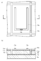
- FIG. 2A is a view of one solar battery cell as viewed from above
- FIG. 2B is a cross-sectional view taken along the line AA ′ in FIG.
- One cell has a width of 0.6 cm and a length of 1 cm, and the area excluding the negative electrode 15a is 0.5 cm 2.
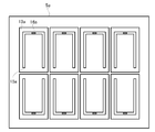
- FIG. 3 a total of eight cells are placed on one glass substrate 5a. Obtained.
- a CIGS solar cell for evaluation (evaluation glass substrate 5a on which the above eight cells were prepared) was installed in a solar simulator (YSS-T80A manufactured by Yamashita Denso Co., Ltd.) and added to the positive electrode 7a previously coated with InGa solvent.
- a terminal (not shown) was connected to the voltage generator at the lower end of the U-shape of the negative electrode 15a.
- the temperature in the solar simulator was controlled at a constant temperature of 25 ° C. with a temperature controller. Pseudo sunlight was irradiated, and after 10 seconds, the voltage was changed from -1 V to +1 V at an interval of 0.015 V, and the current values of each of the eight cells were measured.
- the power generation efficiency was calculated by the following formula (4) from the current and voltage characteristics during irradiation.
- the values of the most efficient cell among the eight cells are shown in Tables 1 to 6 as the value of the power generation efficiency of each glass substrate.
- the illuminance of the light source used for the test was 0.1 W / cm 2 .
- Power generation efficiency [%] Voc [V] ⁇ Jsc [A / cm 2 ] ⁇ FF [Dimensionless] ⁇ 100 / Illuminance [W / cm 2 ] of the light source used in the test Equation (4)
- the power generation efficiency is obtained by multiplying the open circuit voltage (Voc), the short circuit current density (Jsc), and the fill factor (FF).
- the open circuit voltage (Voc) is an output when the terminal is opened, and the short circuit current (Isc) is a current when the terminal is short circuited.
- the short circuit current density (Jsc) is Isc divided by the cell area excluding the negative electrode.
- the point that gives the maximum output is called the maximum output point, the voltage at that point is called the maximum voltage value (Vmax), and the current is called the maximum current value (Imax).
- Vmax the voltage at that point
- Imax the current
- a value obtained by dividing the product of the maximum voltage value (Vmax) and the maximum current value (Imax) by the product of the open circuit voltage (Voc) and the short circuit current (Isc) is obtained as a fill factor (FF). Using the above values, the power generation efficiency was determined.
- the residual amount of SO 3 in the glass was 100 to 500 ppm.
- the glass substrate of Example (Examples 1 to 35), T 4 -T L is not less -30 ° C. or higher, the glass transition temperature T g is as high as 640 ° C. or higher, 50
- the average thermal expansion coefficient at -350 ° C is 70 ⁇ 10 -7 -90 ⁇ 10 -7 / ° C, the density is 2.7 g / cm 3 or less, and the properties of the glass substrate for CIGS solar cells are well balanced.
- the glass substrates of the examples (Examples 1 to 35) are a result of high power generation efficiency, and the brittleness index value is less than 7000 m ⁇ 1/2 .
- the CIGS crystal grows well, and the power generation efficiency decreases due to donor formation by the alkaline earth element diffusion in the CIGS layer. It is considered that the diffusion of Na to the CIGS layer is sufficient and the power generation efficiency is improved.
- the integrated intensity in the molybdenum film was measured by secondary ion mass spectrometry (SIMS) similarly to Ca and Na. Both the examples and comparative examples were below the detection limit.
- the CIGS photoelectric conversion layer does not peel from the glass substrate with molybdenum film, and when the solar cell in the present invention is assembled (specifically, the glass substrate having the CIGS photoelectric conversion layer and the cover glass are heated).
- the glass substrate is not easily deformed, is lightweight, does not devitrify, and has better power generation efficiency.
- T 2 is 1650 ° C. or less, because T 4 is 1230 ° C. or less, solubility during glass sheet production, excellent in moldability.
- Example 39 contains many SrO and BaO, it is thought that a density is large and a brittleness index value is high.
- the comparative examples (Examples 40 to 42) are inferior in power generation efficiency. This is probably because the Ca diffusion amount is large and the Na diffusion amount is small.
- the glass substrate for a Cu—In—Ga—Se solar cell of the present invention is suitable as a glass substrate and cover glass for CIGS solar cells, but can also be used for other solar cell substrates and cover glasses.
Landscapes
- Chemical & Material Sciences (AREA)
- Life Sciences & Earth Sciences (AREA)
- Engineering & Computer Science (AREA)
- Chemical Kinetics & Catalysis (AREA)
- General Chemical & Material Sciences (AREA)
- Geochemistry & Mineralogy (AREA)
- Materials Engineering (AREA)
- Organic Chemistry (AREA)
- Glass Compositions (AREA)
- Photovoltaic Devices (AREA)
Abstract
Description
また、効率の良い太陽電池を得るため、高温の熱処理温度に耐えうるガラス材料の提案もされている(特許文献1および2参照)。
また、特許文献2の方法は、アルカリ制御層を設けることで、高歪点ガラスに含まれる低濃度のアルカリ元素を効率よくp型光吸収層に拡散することを目的としている。しかし、アルカリ制御層を設ける工程が増えるためコストがかかり、またアルカリ制御層によりアルカリ元素の拡散が不十分になり、効率低下のおそれがある。
このようにCIGS太陽電池に使用されるガラス基板において高い発電効率、高いガラス転移点温度、所定の平均熱膨張係数、高いガラス強度、低いガラス密度、板ガラス生産時の溶解性、成形性、失透防止の特性をバランスよく有することは困難であった。
(1)下記酸化物基準のモル百分率表示で、
SiO2を60~75%、
Al2O3を1~7.5%、
B2O3を0~1%、
MgOを8.5~12.5%、
CaOを1~6.5%、
SrOを0~3%、
BaOを0~3%、
ZrO2を0~3%、
TiO2を0~3%、
Na2Oを1~8%、
K2Oを2~12%含有し、
MgO+CaO+SrO+BaOが10~24%、
Na2O+K2Oが5~15%、
MgO/Al2O3が1.3以上、
(2Na2O+K2O+SrO+BaO)/(Al2O3+ZrO2)が3.3以下、
Na2O/K2Oが0.2~2.0、
Al2O3≧-0.94MgO+11、
CaO≧-0.48MgO+6.5であり、
ガラス転移点温度が640℃以上、50~350℃における平均熱膨張係数が70×10-7~90×10-7/℃、粘度が104dPa・sとなる温度(T4)が1230℃以下、粘度が102dPa・sとなる温度(T2)が1650℃以下、前記T4と失透温度(TL)との関係がT4-TL≧-30℃、密度が2.7g/cm3以下であるCu-In-Ga-Se太陽電池用ガラス基板。
SiO2を62~73%、
Al2O3を1.5~7%、
B2O3を0~1%、
MgOを9~12.5%、
CaOを1.5~6.5%、
SrOを0~2.5%、
BaOを0~2%、
ZrO2を0.5~3%、
TiO2を0~3%、
Na2Oを1~7.5%、
K2Oを2~10%含有し、
MgO+CaO+SrO+BaOが11~22%、
Na2O+K2Oが6~13%、
MgO/Al2O3が1.4以上、
(2Na2O+K2O+SrO+BaO)/(Al2O3+ZrO2)が0.5~3、
Na2O/K2Oが0.4~1.7、
Al2O3≧-0.94MgO+12、
CaO≧-0.48MgO+7であり、
ガラス転移点温度が645℃以上、50~350℃における平均熱膨張係数が70×10-7~85×10-7/℃、粘度が104dPa・sとなる温度(T4)が1220℃以下、粘度が102dPa・sとなる温度(T2)が1630℃以下、前記T4と失透温度(TL)との関係がT4-TL≧-20℃、密度が2.65g/cm3以下である上記(1)記載のCu-In-Ga-Se太陽電池用ガラス基板。
MgO/(MgO+CaO+SrO+BaO)が0.4~0.9である上記(1)または(2)に記載のCu-In-Ga-Se太陽電池用ガラス基板。
(4)ガラス基板と、カバーガラスと、前記ガラス基板と前記カバーガラスとの間に配置されるCu-In-Ga-Seの光電変換層と、を有し、
前記ガラス基板と前記カバーガラスのうち少なくとも前記ガラス基板が、(1)~(3)のいずれか一つに記載のCu-In-Ga-Se太陽電池用ガラス基板である太陽電池。
本願の開示は、2011年1月28日に出願された特願2011-016475号に記載の主題と関連しており、それらの開示内容は引用によりここに援用される。
以下、本発明のCu-In-Ga-Se太陽電池用ガラス基板について説明する。
本発明のCu-In-Ga-Se太陽電池用ガラス基板は、下記酸化物基準のモル百分率表示で、
SiO2を60~75%、
Al2O3を1~7.5%、
B2O3を0~1%、
MgOを8.5~12.5%、
CaOを1~6.5%、
SrOを0~3%、
BaOを0~3%、
ZrO2を0~3%、
TiO2を0~3%、
Na2Oを1~8%、
K2Oを2~12%含有し、
MgO+CaO+SrO+BaOが10~24%、
Na2O+K2Oが5~15%、
MgO/Al2O3が1.3以上、
(2Na2O+K2O+SrO+BaO)/(Al2O3+ZrO2)が3.3以下、
Na2O/K2Oが0.2~2.0、
Al2O3≧-0.94MgO+11、
CaO≧-0.48MgO+6.5であり、
ガラス転移点温度が640℃以上、50~350℃における平均熱膨張係数が70×10-7~90×10-7/℃、粘度が104dPa・sとなる温度(T4)が1230℃以下、粘度が102dPa・sとなる温度(T2)が1650℃以下、前記T4と失透温度(TL)との関係がT4-TL≧-30℃、密度が2.7g/cm3以下である、Cu-In-Ga-Se太陽電池用ガラス基板である。なおCu-In-Ga-Seを以下「CIGS」と記載する。
ガラス板の成形性、即ち、平坦性向上、生産性向上を考慮すると、T4は1230℃以下である。T4は1220℃以下が好ましく、1210℃以下がより好ましい。
本発明において、ガラス基板の脆さ指標値は、下記式(1)により定義される「B」として得られるものである(J.Sehgal, et al.,J.Mat.Sci.Lett.,14,167(1995))。
c/a=0.0056B2/3P1/6 (1)
ここで、Pはビッカース圧子の押し込み荷重であり、a、cはそれぞれ、ビッカース圧痕の対角長および四隅から発生するクラックの長さ(圧痕を含む対称な2つのクラックの全長)である。各種ガラス基板の表面に打ち込んだビッカース圧痕の寸法と式(1)を用いて、脆さ指標値Bを算出することとする。
SiO2:ガラスの骨格を形成する成分で、60モル%(以下単に%と記載する)未満ではガラス基板の耐熱性および化学的耐久性が低下し、50~350℃における平均熱膨張係数が増大するおそれがある。好ましくは62%以上であり、より好ましくは63%以上であり、さらに好ましくは64%以上である。
しかし、75%超ではガラスの高温粘度が上昇し、溶解性が悪化する問題が生じるおそれがある。好ましくは73%以下であり、より好ましくは70%以下であり、さらに好ましくは69%以下である。
しかし、7.5%超では、ガラスの高温粘度が上昇し、溶解性が悪くなるおそれがある。また、失透温度が上昇し、成形性が悪くなるおそれがある。また発電効率が低下するおそれがある。好ましくは7%以下である。
なお、「実質的に含有しない」とは、原料等から混入する不可避的不純物以外には含有しないこと、すなわち、意図的に含有させないことを意味する。
しかし、12.5%超では、50~350℃における平均熱膨張係数が増大するおそれがある。また失透温度が上昇するおそれがある。好ましくは12%以下である。
MgO/(MgO+CaO+SrO+BaO) (2)
アルカリ土類金属は、光電変換層のp型半導体であるCIGS層へ拡散するとドナーとして働くため、発電効率を低下させるおそれがある。また、アルカリ土類金属の拡散は、太陽電池製造工程中のCIGS層を形成する際、Cu、In、GaとSeとの化合物形成に影響を与えると考えられ、その結果、結晶成長にも影響を与えると考えられる。例えば、Cu、In、Ga、Seの未反応元素が残存し、CIGS結晶の作製を妨げることが考えられる。その結果、発電効率も低下するおそれがある。一方でアルカリ土類金属元素はガラスの溶解性改善のために必須である。
上記式(2)が0.9を超えると、溶解性が悪化する場合があるため、0.9以下であることが好ましい。より好ましくは0.85以下、さらに好ましくは0.8以下である。
Na2O含有量が8%を超えると50~350℃における平均熱膨張係数が大きくなり、ガラス転移点温度が低下する傾向がある。または化学的耐久性が劣化する。または、ヤング率が低下するおそれがある。含有量が7.5%以下であると好ましく、7%以下であるとより好ましい。
(2Na2O+K2O+SrO+BaO)/(Al2O3+ZrO2) (3)
本発明者等は、実験および試行錯誤の結果から、上記の各成分が本願の範囲を満たし、且つ、上記式で得られる値が3.3以下となる場合に、ガラス転移点温度を十分に高く保ちつつ、発電効率が良好となることを見出した。好ましくは3以下であり、より好ましくは2.8以下である。
3.3を超えると、ガラス転移点温度が低くなる、もしくは耐候性が悪化するおそれがある。また、数値が低くなりすぎると高温での粘性が高くなり、溶解性や成形性が低下する傾向があるため好ましくは0.5以上であり、より好ましくは1以上である。
なお、Na2Oに2の係数が付いているのはTgを低くする効果が他の成分より高いためである。
SiO2を62~73%、
Al2O3を1.5~7%、
B2O3を0~1%、
MgOを9~12.5%、
CaOを1.5~6.5%、
SrOを0~2.5%、
BaOを0~2%、
ZrO2を0.5~3%、
TiO2を0~3%、
Na2Oを1~7.5%、
K2Oを2~10%含有し、
MgO+CaO+SrO+BaOが11~22%、
Na2O+K2Oが6~13%、
MgO/Al2O3が1.4以上、
(2Na2O+K2O+SrO+BaO)/(Al2O3+ZrO2)が0.5~3、
Na2O/K2Oが0.4~1.7、
Al2O3≧-0.94MgO+12、
CaO≧-0.48MgO+7であり、
ガラス転移点温度が645℃以上、50~350℃における平均熱膨張係数が70×10-7~85×10-7/℃、粘度が104dPa・sとなる温度(T4)が1220℃以下、粘度が102dPa・sとなる温度(T2)が1630℃以下、前記T4と失透温度(TL)との関係がT4-TL≧-20℃、密度が2.65g/cm3以下であるCu-In-Ga-Se太陽電池用ガラス基板が好ましい。
ガラス基板の化学的耐久性向上のため、ガラス基板の組成物中にY2O3、La2O3を合量で2%以下含有させてもよい。
本発明のCIGS太陽電池用ガラス基板は、環境負荷を考慮すると、As2O3、Sb2O3を実質的に含有しないことが好ましい。また、安定してフロート成形することを考慮すると、ZnOを実質的に含有しないことが好ましい。しかし、本発明のCIGS太陽電池用ガラス基板は、フロート法による成形に限らず、フュージョン法による成形により製造してもよい。
本発明のCIGS太陽電池用ガラス基板の製造方法について説明する。
本発明のCIGS太陽電池用ガラス基板を製造する場合、従来の太陽電池用ガラス基板を製造する際と同様に、溶解・清澄工程および成形工程を実施する。なお、本発明のCIGS太陽電池用ガラス基板は、アルカリ金属酸化物(Na2O、K2O)を含有するアルカリガラス基板であるため、清澄剤としてSO3を効果的に用いることができ、成形方法としてフロート法およびフュージョン法(ダウンドロー法)に適している。
太陽電池用のガラス基板の製造工程において、ガラスを板状に成形する方法としては、太陽電池の大型化に伴い、大面積のガラス基板を容易に、安定して成形できるフロート法を用いることが好ましい。
初めに、原料を溶解して得た溶融ガラスを板状に成形する。例えば、得られるガラス基板が上記組成となるように原料を調製し、上記原料を溶解炉に連続的に投入し、1550~1700℃に加熱して溶融ガラスを得る。そしてこの溶融ガラスを例えばフロート法を適用してリボン状のガラス板に成形する。
次に、リボン状のガラス板をフロート成形炉から引出した後に、冷却手段によって室温状態まで冷却し、切断後、CIGS太陽電池用ガラス基板を得る。
本発明のCIGS太陽電池用ガラス基板は、CIGS太陽電池のガラス基板、またカバーガラスとしても好適である。特に本発明のガラス基板は、セレン化法により製造されるCIGS太陽電池用ガラス基板として好適である。
本発明のCIGS太陽電池用ガラス基板をCIGS太陽電池のガラス基板に適用する場合、ガラス基板の厚さは3mm以下とするのが好ましく、より好ましくは2mm以下、さらに好ましくは1.5mm以下である。またガラス基板にCIGS層を付与する方法は特に制限されない。
本願発明のCIGS太陽電池用ガラス基板を用いることで、CIGS層を形成する際の加熱温度を500~700℃、好ましくは600~700℃とすることができる。
本発明のCIGS太陽電池用ガラス基板をCIGS太陽電池のガラス基板のみに使用する場合、カバーガラス等は特に制限されない。カバーガラスの組成の他の例は、ソーダライムガラス等が挙げられる。
本発明のCIGS太陽電池用ガラス基板を用いることで、加熱して組立てる場合、その加熱温度を500~700℃、好ましくは600~700℃とすることができる。
次に、本発明における太陽電池について説明する。
本発明における太陽電池は、ガラス基板と、カバーガラスと、上記ガラス基板と上記カバーガラスとの間に配置されるCu-In-Ga-Seの光電変換層と、を有し、
上記ガラス基板と上記カバーガラスのうち少なくとも上記ガラス基板が、本発明のCu-In-Ga-Se太陽電池用ガラス基板である。
図1は本発明における太陽電池の実施形態の一例を模式的に表す断面図である。
図1において、本発明におけるCIGS太陽電池1は、ガラス基板5、カバーガラス19、およびガラス基板5とカバーガラス19との間にCIGS層9を有する。ガラス基板5は、上記で説明した本発明のCIGS太陽電池用ガラス基板からなるのが好ましい。太陽電池1はガラス基板5上にプラス電極7であるモリブデン膜の裏面電極層を有し、その上にCIGS層9を有する。CIGS層の組成はCu(In1-xGax)Se2が例示できる。xはInとGaの組成比を示すもので0<x<1である。
CIGS層9上にはバッファ層11として、CdS(硫化カドミウム)、ZnS(亜鉛硫化物)層、ZnO(酸化亜鉛)層、Zn(OH)2(水酸化亜鉛)層、またはこれらの混晶層を有する。バッファ層11を介して、ZnO、ITO、またはAlをドープしたZnO(AZO)等の透明導電膜13を有し、さらにその上にマイナス電極15であるAl電極(アルミニウム電極)等の取出し電極を有する。これらの層の間の必要な場所には反射防止膜を設けてもよい。図1においては、透明導電膜13とマイナス電極15との間に反射防止膜17が設けられている。
本発明においてCIGS層の端部または太陽電池の端部は封止されていてもよい。封止するための材料としては、例えば本発明のCIGS太陽電池用ガラス基板と同じ材料、そのほかのガラス、樹脂等が挙げられる。
なお添付の図面に示す太陽電池の各層の厚さは図面に限定されない。
本発明のCIGS太陽電池用ガラス基板の実施例(例1~35)および比較例(例36~42)を示す。なお表1~6中のかっこは、計算値である。
こうして得られたガラス板の50~350℃における平均熱膨張係数(単位:×10-7/℃)、ガラス転移点温度Tg(単位:℃)、粘度が104dPa・sとなる温度(T4)(単位:℃)、粘度が102dPa・sとなる温度(T2)(単位:℃)、失透温度(TL)(単位:℃)、密度(単位:g/cm3)、脆さ指標値(単位:m-1/2)、ヤング率(単位:GPa)、発電効率(単位:%)、Ca拡散量、Na拡散量を測定し、表1~6に示した。以下に各物性の測定方法を示す。
なお、実施例では、ガラス板について測定しているが、各物性は、ガラス板とガラス基板とで同じ値である。得られたガラス板を加工、研磨を施すことで、ガラス基板とすることができる。
(2)50~350℃の平均熱膨張係数:示差熱膨張計(TMA)を用いて測定し、JIS R3102(1995年度)より求めた。
(3)粘度:回転粘度計を用いて測定し、粘度ηが102dPa・sとなるときの温度T2(溶解性の基準温度)と、粘度ηが104dPa・sとなるときの温度T4(成形性の基準温度)を測定した。
(5)密度:泡を含まない約20gのガラス塊をアルキメデス法によって測定した。
(6)脆さ指標値:前述の各種ガラス板をガラス基板とし、そのガラス基板の表面に打ち込んだビッカース圧痕の寸法と上記式(1)を用いて、脆さ指標値Bを算出する。
(7)ヤング率:厚み7~10mmのガラスについて、超音波パルス法により測定した。
評価用太陽電池の作製について、図2、3およびその符号を用いて以下説明している。なお、評価用太陽電池の層構成は、図1の太陽電池のカバーガラス19および反射防止膜17を有さない以外は、図1に示す太陽電池の層構成とほぼ同様である。
得られたガラス板を大きさ3cm×3cm、厚さ1.1mmに加工し、ガラス基板を得た。ガラス基板5aの上に、スパッタ装置にて、プラス電極7aとしてモリブデン膜を成膜した。成膜は室温にて実施し、厚み500nmのモリブデン膜を得た。
プラス電極7a(モリブデン膜)上にスパッタ装置にて、CuGa合金ターゲットでCuGa合金層を成膜し、続いてInターゲットを使用してIn層を成膜することで、In-CuGaのプリカーサ膜を成膜した。成膜は室温にて実施した。蛍光X線によって測定したプリカーサ膜の組成が、Cu/(Ga+In)比(原子比)が0.8、Ga/(Ga+In)比(原子比)が0.25となるように各層の厚みを調整し、厚み650nmのプリカーサ膜を得た。
まず、条件1では、セレン化水素雰囲気にて、第1段階として250℃で30分保持を行い、CuとInとGaとを、Seと反応させて、その後、第2段階としてさらに520℃で60分保持してCIGS結晶を成長させることでCIGS層9aを得た。
また、条件2では、セレン化水素雰囲気にて、第1段階として250℃で30分保持を行い、CuとInとGaとを、Seと反応させて、その後、第2段階として硫化水素雰囲気に置換した後、さらに600℃で30分保持することによりCIGS結晶を硫化処理し、CIGS結晶の一部のSeをSに置換することで、条件1に比べてバンドギャップの大きいCIGS層9aを得た。
どちらの条件においても、得られたCIGS層9aの厚みは2μmであった。
透明導電膜13aのAZO層上にEB蒸着法により、U字型のマイナス電極15aとして膜厚1μmのアルミ膜を成膜した(U字の電極長(縦8mm、横4mm)、電極幅0.5mm)。
ソーラーシミュレータ(山下電装株式会社製、YSS-T80A)に、評価用CIGS太陽電池(上記8個のセルを作製した評価用ガラス基板5a)を設置し、あらかじめInGa溶剤を塗布したプラス電極7aにプラス端子を(不図示)、マイナス電極15aのU字の下端にマイナス端子16aをそれぞれ電圧発生器に接続した。ソーラーシミュレータ内の温度は25℃一定に温度調節機にて制御した。疑似太陽光を照射し、10秒後に、電圧を-1Vから+1Vまで0.015V間隔で変化させ、8個のセルのそれぞれの電流値を測定した。
発電効率[%]=Voc[V]×Jsc[A/cm2]×FF[無次元]×100/試験に用いる光源の照度[W/cm2] 式(4)
なお、開放電圧(Voc)は端子を開放した時の出力であり、短絡電流(Isc)は短絡した時の電流である。短絡電流密度(Jsc)はIscをマイナス電極を除いたセルの面積で割ったものである。
上記RTA装置による加熱の第1段階終了後、試料を二次イオン質量分析法(SIMS、アルバック・ファイ社製の製品名:ADEPT1010を使用)にてモリブデン膜中の40Caの積分強度を測定し、Ca拡散量の指標とした。
なお、SIMSによる積分強度の測定は、測定日毎にリファレンスとして例10のガラス基板を測定し、その値を基準にした数値をCa拡散量とした。
なお、SIMSによる積分強度の測定は、測定日毎にリファレンスとして例10のガラス基板を測定し、その値を基準にした数値をNa拡散量とした。


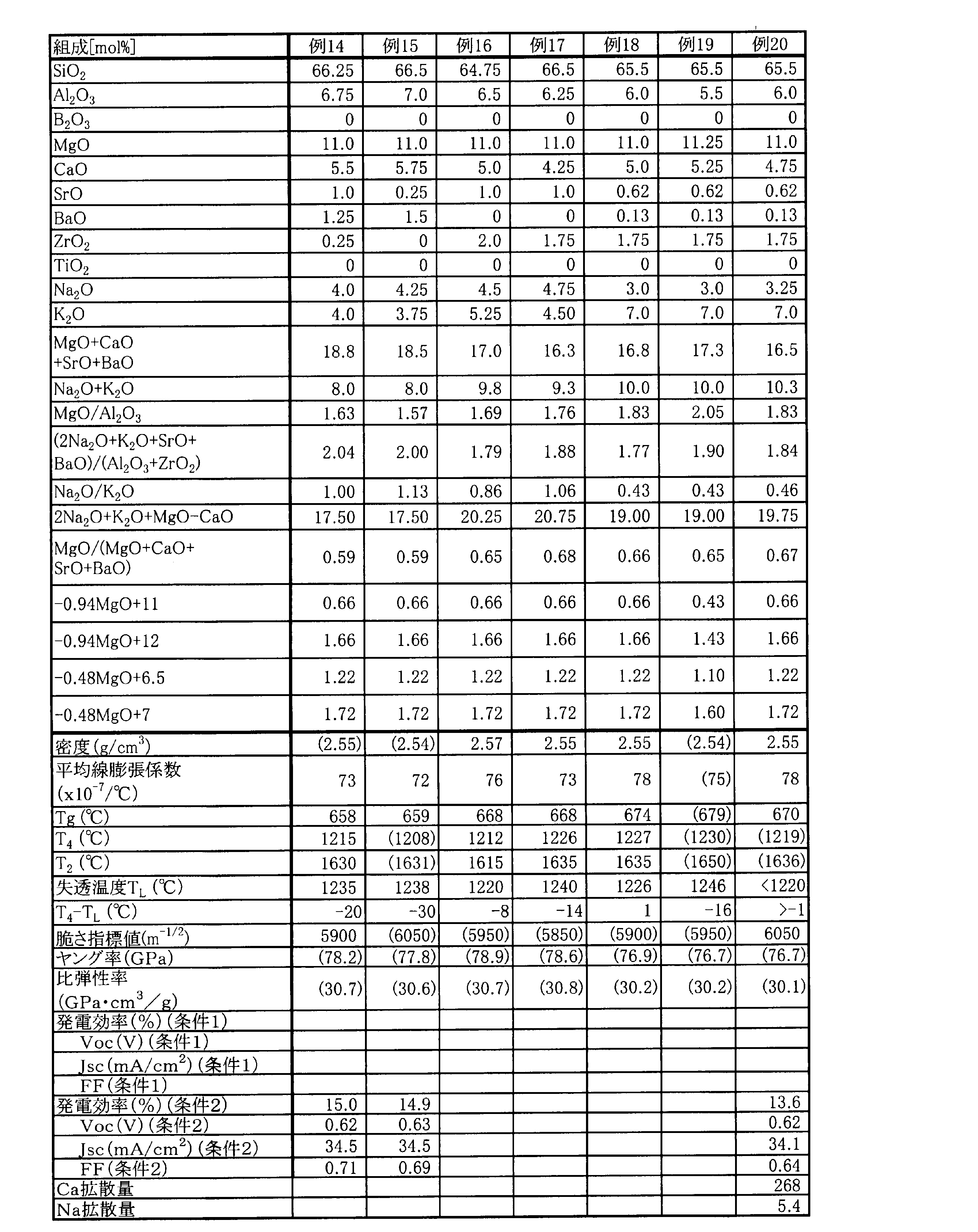
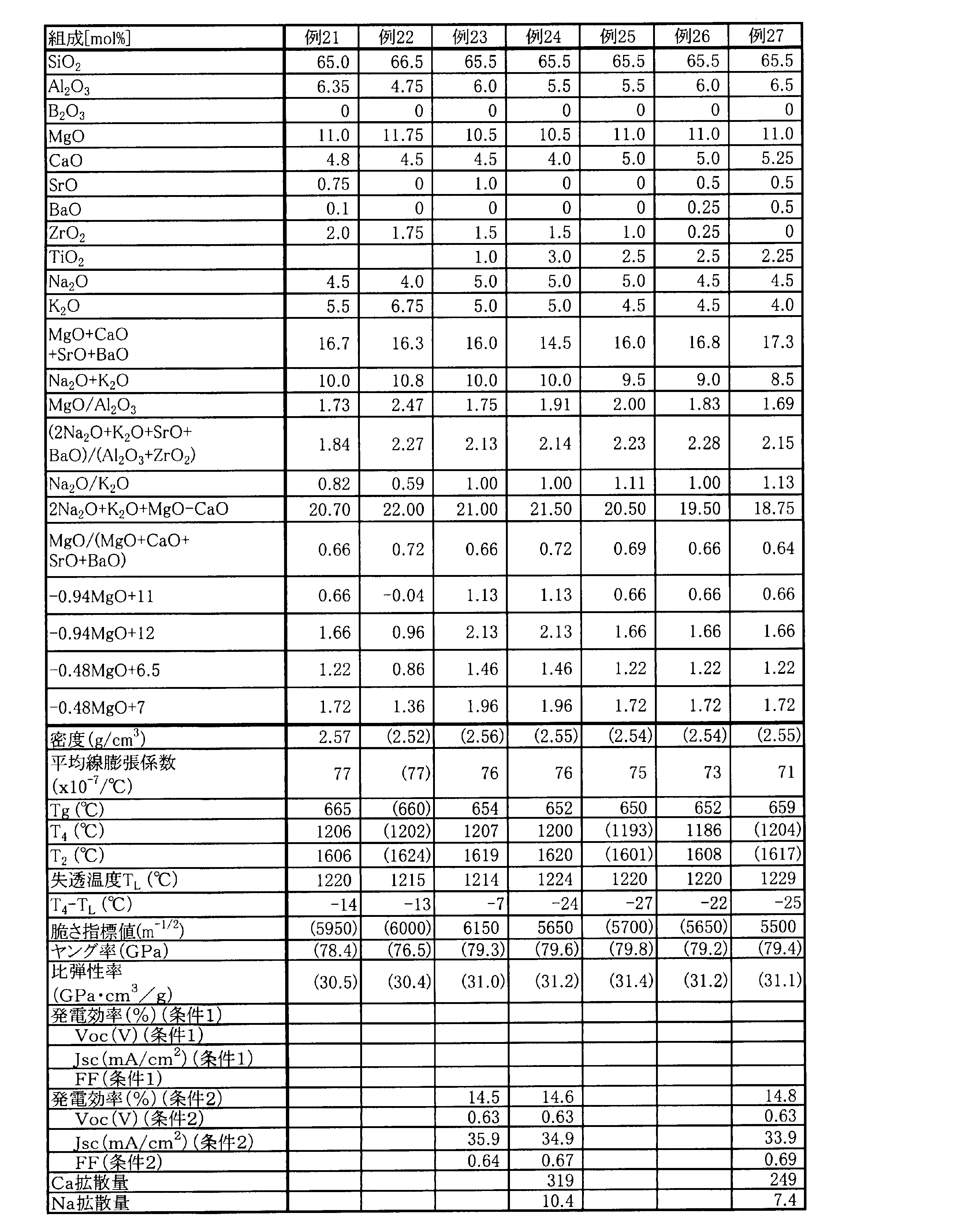


また、実施例(例1~35)のガラス基板は、発電効率が高い結果であり、脆さ指標値は7000m-1/2未満となる。
なお、Mg、Sr、BaについてもCa、Naと同様に二次イオン質量分析法(SIMS)によりモリブデン膜中の積分強度を測定した。実施例、比較例ともに検出限界以下であった。
比較例(例39)はTgが低く、600℃以上での成膜時にガラス基板が変形しやすい。また、例39は、SrO、BaOを多く含有するため、密度が大きく脆さ指標値が高いと考えられる。
また比較例(例40~42)は発電効率が劣る。これは、Ca拡散量が多く、Na拡散量が少ないためと考えられる。
5、5a ガラス基板
7、7a プラス電極
9、9a CIGS層
11、11a バッファ層
13、13a 透明導電膜
15、15a マイナス電極
16a マイナス端子
17 反射防止膜
19 カバーガラス
Claims (4)
- 下記酸化物基準のモル百分率表示で、
SiO2を60~75%、
Al2O3を1~7.5%、
B2O3を0~1%、
MgOを8.5~12.5%、
CaOを1~6.5%、
SrOを0~3%、
BaOを0~3%、
ZrO2を0~3%、
TiO2を0~3%、
Na2Oを1~8%、
K2Oを2~12%含有し、
MgO+CaO+SrO+BaOが10~24%、
Na2O+K2Oが5~15%、
MgO/Al2O3が1.3以上、
(2Na2O+K2O+SrO+BaO)/(Al2O3+ZrO2)が3.3以下、
Na2O/K2Oが0.2~2.0、
Al2O3≧-0.94MgO+11、
CaO≧-0.48MgO+6.5であり、
ガラス転移点温度が640℃以上、50~350℃における平均熱膨張係数が70×10-7~90×10-7/℃、粘度が104dPa・sとなる温度(T4)が1230℃以下、粘度が102dPa・sとなる温度(T2)が1650℃以下、前記T4と失透温度(TL)との関係がT4-TL≧-30℃、密度が2.7g/cm3以下であるCu-In-Ga-Se太陽電池用ガラス基板。 - 下記酸化物基準のモル百分率表示で、
SiO2を62~73%、
Al2O3を1.5~7%、
B2O3を0~1%、
MgOを9~12.5%、
CaOを1.5~6.5%、
SrOを0~2.5%、
BaOを0~2%、
ZrO2を0.5~3%、
TiO2を0~3%、
Na2Oを1~7.5%、
K2Oを2~10%含有し、
MgO+CaO+SrO+BaOが11~22%、
Na2O+K2Oが6~13%、
MgO/Al2O3が1.4以上、
(2Na2O+K2O+SrO+BaO)/(Al2O3+ZrO2)が0.5~3、
Na2O/K2Oが0.4~1.7、
Al2O3≧-0.94MgO+12、
CaO≧-0.48MgO+7であり、
ガラス転移点温度が645℃以上、50~350℃における平均熱膨張係数が70×10-7~85×10-7/℃、粘度が104dPa・sとなる温度(T4)が1220℃以下、粘度が102dPa・sとなる温度(T2)が1630℃以下、前記T4と失透温度(TL)との関係がT4-TL≧-20℃、密度が2.65g/cm3以下である請求項1に記載のCu-In-Ga-Se太陽電池用ガラス基板。 - 下記酸化物基準のモル百分率表示で、
MgO/(MgO+CaO+SrO+BaO)が0.4~0.9である請求項1または2に記載のCu-In-Ga-Se太陽電池用ガラス基板。 - ガラス基板と、カバーガラスと、前記ガラス基板と前記カバーガラスとの間に配置されるCu-In-Ga-Seの光電変換層と、を有し、
前記ガラス基板と前記カバーガラスのうち少なくとも前記ガラス基板が、請求項1~3のいずれか一項に記載のCu-In-Ga-Se太陽電池用ガラス基板である太陽電池。
Priority Applications (4)
| Application Number | Priority Date | Filing Date | Title |
|---|---|---|---|
| JP2012554841A JPWO2012102346A1 (ja) | 2011-01-28 | 2012-01-26 | Cu−In−Ga−Se太陽電池用ガラス基板およびそれを用いた太陽電池 |
| CN201280006759XA CN103339745A (zh) | 2011-01-28 | 2012-01-26 | Cu-In-Ga-Se太阳能电池用玻璃基板及使用该玻璃基板的太阳能电池 |
| KR1020137019839A KR20140015314A (ko) | 2011-01-28 | 2012-01-26 | Cu-In-Ga-Se 태양 전지용 유리 기판 및 그것을 사용한 태양 전지 |
| US13/952,936 US20130306145A1 (en) | 2011-01-28 | 2013-07-29 | Glass substrate for cu-in-ga-se solar cell and solar cell using same |
Applications Claiming Priority (2)
| Application Number | Priority Date | Filing Date | Title |
|---|---|---|---|
| JP2011016475 | 2011-01-28 | ||
| JP2011-016475 | 2011-01-28 |
Related Child Applications (1)
| Application Number | Title | Priority Date | Filing Date |
|---|---|---|---|
| US13/952,936 Continuation US20130306145A1 (en) | 2011-01-28 | 2013-07-29 | Glass substrate for cu-in-ga-se solar cell and solar cell using same |
Publications (1)
| Publication Number | Publication Date |
|---|---|
| WO2012102346A1 true WO2012102346A1 (ja) | 2012-08-02 |
Family
ID=46580910
Family Applications (1)
| Application Number | Title | Priority Date | Filing Date |
|---|---|---|---|
| PCT/JP2012/051693 Ceased WO2012102346A1 (ja) | 2011-01-28 | 2012-01-26 | Cu-In-Ga-Se太陽電池用ガラス基板およびそれを用いた太陽電池 |
Country Status (6)
| Country | Link |
|---|---|
| US (1) | US20130306145A1 (ja) |
| JP (1) | JPWO2012102346A1 (ja) |
| KR (1) | KR20140015314A (ja) |
| CN (1) | CN103339745A (ja) |
| TW (1) | TW201231429A (ja) |
| WO (1) | WO2012102346A1 (ja) |
Cited By (5)
| Publication number | Priority date | Publication date | Assignee | Title |
|---|---|---|---|---|
| JP2014067903A (ja) * | 2012-09-26 | 2014-04-17 | Asahi Glass Co Ltd | 太陽電池用ガラス基板、太陽電池、および太陽電池の製造方法 |
| JP2014097916A (ja) * | 2012-11-16 | 2014-05-29 | Nippon Electric Glass Co Ltd | 薄膜太陽電池用ガラス板及びその製造方法 |
| JP2015233134A (ja) * | 2014-05-15 | 2015-12-24 | 旭硝子株式会社 | 太陽電池用ガラス基板及びそれを用いた太陽電池 |
| JP2016147792A (ja) * | 2015-02-13 | 2016-08-18 | 旭硝子株式会社 | ガラス基板 |
| JPWO2022255337A1 (ja) * | 2021-05-31 | 2022-12-08 |
Families Citing this family (8)
| Publication number | Priority date | Publication date | Assignee | Title |
|---|---|---|---|---|
| JPWO2011049146A1 (ja) * | 2009-10-20 | 2013-03-14 | 旭硝子株式会社 | Cu−In−Ga−Se太陽電池用ガラス板およびこれを用いた太陽電池 |
| GB201505091D0 (en) | 2015-03-26 | 2015-05-06 | Pilkington Group Ltd | Glass |
| US9859451B2 (en) * | 2015-06-26 | 2018-01-02 | International Business Machines Corporation | Thin film photovoltaic cell with back contacts |
| CN110944953A (zh) * | 2017-07-26 | 2020-03-31 | Agc株式会社 | 半导体封装用支承玻璃 |
| CN108129020B (zh) * | 2017-12-13 | 2019-06-07 | 东旭科技集团有限公司 | 一种玻璃用组合物、铝硅酸盐玻璃及其制备方法和应用 |
| WO2020150422A1 (en) * | 2019-01-18 | 2020-07-23 | Corning Incorporated | Low dielectric loss glasses for electronic devices |
| US11951713B2 (en) | 2020-12-10 | 2024-04-09 | Corning Incorporated | Glass with unique fracture behavior for vehicle windshield |
| US12122714B2 (en) | 2020-12-10 | 2024-10-22 | Corning Incorporated | Glass with unique fracture behavior for vehicle windshield |
Citations (5)
| Publication number | Priority date | Publication date | Assignee | Title |
|---|---|---|---|---|
| JPH11314933A (ja) * | 1998-02-27 | 1999-11-16 | Asahi Glass Co Ltd | 基板用ガラス組成物 |
| WO2009054419A1 (ja) * | 2007-10-25 | 2009-04-30 | Asahi Glass Company, Limited | 基板用ガラス組成物およびその製造方法 |
| WO2011049146A1 (ja) * | 2009-10-20 | 2011-04-28 | 旭硝子株式会社 | Cu-In-Ga-Se太陽電池用ガラス板およびこれを用いた太陽電池 |
| WO2011152414A1 (ja) * | 2010-06-03 | 2011-12-08 | 旭硝子株式会社 | ガラス基板およびその製造方法 |
| WO2012014854A1 (ja) * | 2010-07-26 | 2012-02-02 | 旭硝子株式会社 | Cu-In-Ga-Se太陽電池用ガラス基板及びそれを用いた太陽電池 |
Family Cites Families (4)
| Publication number | Priority date | Publication date | Assignee | Title |
|---|---|---|---|---|
| JPH11240735A (ja) * | 1998-02-27 | 1999-09-07 | Asahi Glass Co Ltd | 基板として用いるためのガラス組成物 |
| US20080302418A1 (en) * | 2006-03-18 | 2008-12-11 | Benyamin Buller | Elongated Photovoltaic Devices in Casings |
| US7235736B1 (en) * | 2006-03-18 | 2007-06-26 | Solyndra, Inc. | Monolithic integration of cylindrical solar cells |
| US8349454B2 (en) * | 2007-06-07 | 2013-01-08 | Nippon Electric Glass Co., Ltd. | Strengthened glass substrate and process for producing the same |
-
2012
- 2012-01-26 JP JP2012554841A patent/JPWO2012102346A1/ja not_active Withdrawn
- 2012-01-26 KR KR1020137019839A patent/KR20140015314A/ko not_active Withdrawn
- 2012-01-26 CN CN201280006759XA patent/CN103339745A/zh active Pending
- 2012-01-26 WO PCT/JP2012/051693 patent/WO2012102346A1/ja not_active Ceased
- 2012-01-30 TW TW101102934A patent/TW201231429A/zh unknown
-
2013
- 2013-07-29 US US13/952,936 patent/US20130306145A1/en not_active Abandoned
Patent Citations (5)
| Publication number | Priority date | Publication date | Assignee | Title |
|---|---|---|---|---|
| JPH11314933A (ja) * | 1998-02-27 | 1999-11-16 | Asahi Glass Co Ltd | 基板用ガラス組成物 |
| WO2009054419A1 (ja) * | 2007-10-25 | 2009-04-30 | Asahi Glass Company, Limited | 基板用ガラス組成物およびその製造方法 |
| WO2011049146A1 (ja) * | 2009-10-20 | 2011-04-28 | 旭硝子株式会社 | Cu-In-Ga-Se太陽電池用ガラス板およびこれを用いた太陽電池 |
| WO2011152414A1 (ja) * | 2010-06-03 | 2011-12-08 | 旭硝子株式会社 | ガラス基板およびその製造方法 |
| WO2012014854A1 (ja) * | 2010-07-26 | 2012-02-02 | 旭硝子株式会社 | Cu-In-Ga-Se太陽電池用ガラス基板及びそれを用いた太陽電池 |
Cited By (5)
| Publication number | Priority date | Publication date | Assignee | Title |
|---|---|---|---|---|
| JP2014067903A (ja) * | 2012-09-26 | 2014-04-17 | Asahi Glass Co Ltd | 太陽電池用ガラス基板、太陽電池、および太陽電池の製造方法 |
| JP2014097916A (ja) * | 2012-11-16 | 2014-05-29 | Nippon Electric Glass Co Ltd | 薄膜太陽電池用ガラス板及びその製造方法 |
| JP2015233134A (ja) * | 2014-05-15 | 2015-12-24 | 旭硝子株式会社 | 太陽電池用ガラス基板及びそれを用いた太陽電池 |
| JP2016147792A (ja) * | 2015-02-13 | 2016-08-18 | 旭硝子株式会社 | ガラス基板 |
| JPWO2022255337A1 (ja) * | 2021-05-31 | 2022-12-08 |
Also Published As
| Publication number | Publication date |
|---|---|
| TW201231429A (en) | 2012-08-01 |
| US20130306145A1 (en) | 2013-11-21 |
| CN103339745A (zh) | 2013-10-02 |
| KR20140015314A (ko) | 2014-02-06 |
| JPWO2012102346A1 (ja) | 2014-06-30 |
Similar Documents
| Publication | Publication Date | Title |
|---|---|---|
| JPWO2012102346A1 (ja) | Cu−In−Ga−Se太陽電池用ガラス基板およびそれを用いた太陽電池 | |
| US20130233386A1 (en) | Glass substrate for cu-in-ga-se solar cells and solar cell using same | |
| WO2011049146A1 (ja) | Cu-In-Ga-Se太陽電池用ガラス板およびこれを用いた太陽電池 | |
| JP6048490B2 (ja) | Cu−In−Ga−Se太陽電池用ガラス基板およびそれを用いた太陽電池 | |
| JP6128128B2 (ja) | 太陽電池用ガラス基板およびそれを用いた太陽電池 | |
| JP6210136B2 (ja) | ガラス基板 | |
| JP2016102058A (ja) | 太陽電池用ガラス基板及びそれを用いた太陽電池 | |
| JPWO2015076208A1 (ja) | ガラス板 | |
| JPWO2014024850A1 (ja) | Cu−In−Ga−Se太陽電池用ガラス基板およびそれを用いた太陽電池 | |
| JP6249033B2 (ja) | ガラス板 | |
| JP2014067903A (ja) | 太陽電池用ガラス基板、太陽電池、および太陽電池の製造方法 | |
| JP2016171158A (ja) | Cu−In−Ga−Se太陽電池 |
Legal Events
| Date | Code | Title | Description |
|---|---|---|---|
| 121 | Ep: the epo has been informed by wipo that ep was designated in this application |
Ref document number: 12739261 Country of ref document: EP Kind code of ref document: A1 |
|
| ENP | Entry into the national phase |
Ref document number: 2012554841 Country of ref document: JP Kind code of ref document: A |
|
| ENP | Entry into the national phase |
Ref document number: 20137019839 Country of ref document: KR Kind code of ref document: A |
|
| NENP | Non-entry into the national phase |
Ref country code: DE |
|
| 122 | Ep: pct application non-entry in european phase |
Ref document number: 12739261 Country of ref document: EP Kind code of ref document: A1 |