WO2012093476A1 - 回転電機 - Google Patents
回転電機 Download PDFInfo
- Publication number
- WO2012093476A1 WO2012093476A1 PCT/JP2011/050077 JP2011050077W WO2012093476A1 WO 2012093476 A1 WO2012093476 A1 WO 2012093476A1 JP 2011050077 W JP2011050077 W JP 2011050077W WO 2012093476 A1 WO2012093476 A1 WO 2012093476A1
- Authority
- WO
- WIPO (PCT)
- Prior art keywords
- power
- terminal
- circuit unit
- bus bar
- power module
- Prior art date
Links
Images


Classifications
-
- H—ELECTRICITY
- H02—GENERATION; CONVERSION OR DISTRIBUTION OF ELECTRIC POWER
- H02K—DYNAMO-ELECTRIC MACHINES
- H02K11/00—Structural association of dynamo-electric machines with electric components or with devices for shielding, monitoring or protection
- H02K11/04—Structural association of dynamo-electric machines with electric components or with devices for shielding, monitoring or protection for rectification
- H02K11/049—Rectifiers associated with stationary parts, e.g. stator cores
- H02K11/05—Rectifiers associated with casings, enclosures or brackets
-
- H—ELECTRICITY
- H02—GENERATION; CONVERSION OR DISTRIBUTION OF ELECTRIC POWER
- H02K—DYNAMO-ELECTRIC MACHINES
- H02K5/00—Casings; Enclosures; Supports
- H02K5/04—Casings or enclosures characterised by the shape, form or construction thereof
- H02K5/22—Auxiliary parts of casings not covered by groups H02K5/06-H02K5/20, e.g. shaped to form connection boxes or terminal boxes
- H02K5/225—Terminal boxes or connection arrangements
Definitions
- the present invention relates to a rotating electrical machine in which a control device is mounted on a rotating electrical machine main body.
- a rotating electrical machine in which a control device is mounted on a rotating electrical machine main body is known.
- the control device has a plurality of power modules for controlling power from the rotating electrical machine main body and the battery to adjust the input / output of the rotating electrical machine, and power interconnection parts including a plurality of terminals connected to each power module ing.
- the power interconnection component is disposed at a position overlapping with each power module when viewed along the axis of the rotary electric machine main body (see Patent Document 1).
- the power interconnection parts and the respective power modules are disposed at positions overlapping with each other in the axial direction of the rotary electric machine main body, the axial dimension of the rotary electric machine becomes large.
- the present invention has been made to solve the above-described problems, and an object of the present invention is to obtain a rotating electrical machine capable of reducing the size in the axial direction.
- the rotating electric machine comprises a rotating electric machine main body including a stator, a rotor including a rotating shaft and rotatable with respect to the stator, and a stator and a support for supporting the rotor, and around the rotating shaft.
- Power circuit unit having a control circuit disposed in the rotary electric machine main body, having a power circuit portion arranged between an electric power and a DC electric power received from the rotary electric machine main body and supplied to the rotary electric machine main body
- the power module area is arranged to avoid overlapping.
- the power interconnection component including the conductors individually connected to the terminals of the power module overlaps the area of the power module when the power circuit portion is viewed along the axial direction of the rotation axis.
- the dimension of the axial direction of a power circuit part can be made small, and the dimension of the axial direction of the whole rotary electric machine can be made small.
- FIG. 4 is a front view showing a positive bus bar, a negative bus bar, an armature connection terminal and a field connection terminal when the insulator is removed from the power interconnection component of FIG. 3; It is sectional drawing which shows the part by the side of the rear of the rotary electric machine by Embodiment 2 of this invention. It is a front view which shows a state when a power circuit part and a field circuit part are seen along the axis line of the axis of rotation of FIG.
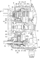
- FIG. 1 is a cross-sectional view showing a rotating electrical machine according to Embodiment 1 of the present invention.
- the rotary electric machine 1 is a control device integrated rotary electric machine having a rotary electric machine main body 2 and a control device 3 mounted on the rotary electric machine main body 2.
- the rotary electric machine 1 is an AC generator motor (motor generator).
- the rotary electric machine main body 2 is a cylindrical stator 4 and a case that is disposed inside the stator 4 and supports the rotor 5 rotatable with respect to the stator 4, the stator 4 and the rotor 5 (support Body) and 6).
- the case 6 has a front bracket 7 and a rear bracket 8 sandwiching the stator 4 in the axial direction of the rotor 5 and a plurality of fastening bolts 9 for fastening between the front bracket 7 and the rear bracket 8.
- the front bracket 7 and the rear bracket 8 are made of metal.
- the stator 4 has a cylindrical stator core 10 fixed to each of the front bracket 7 and the rear bracket 8, and a stator winding (armature winding) 11 provided on the stator core 10. ing.
- the rotor 5 has a rotating shaft 12 disposed on the axis of the rotor 5, a rotor core 13 fixed to an intermediate portion of the rotating shaft 12, and a rotor winding provided on the rotor core 13. And a magnetic winding 14).
- the rotating shaft 12 passes through the front bracket 7 and the rear bracket 8. Further, the rotating shaft 12 is rotatably supported by the front bracket 7 and the rear bracket 8 via bearings 15 respectively.
- the outer peripheral portion of the rotor core 13 faces the inner peripheral portion of the stator 4.
- the rotor core 13 is provided with a cooling fan 16 for blowing that rotates integrally with the rotor 5.
- a pulley 17 is fixed to an end of the rotary shaft 12 on the front bracket 7 side.
- a transmission belt (not shown) interlocked with the rotation shaft of the engine is wound around the pulley 17.
- a rotational position detection sensor 18 that generates a signal according to the rotation of the rotary shaft 12 is provided.
- a plurality of slip rings 19 electrically connected to the rotor winding 14 are provided at a portion of the rotating shaft 12 between the rotor core 13 and the rotational position detection sensor 18.
- the slip ring 19 is an annular conductive member that surrounds the outer peripheral portion of the rotating shaft 12.
- the slip ring 19 is in contact with conductive brushes 20 for supplying the slip ring 19 with a field current for generating a magnetic field in the rotor 5.
- the rear bracket 8 is provided with a brush holder 21 for guiding the brush 20 in a direction in which the brush 20 is in contact with or separated from each slip ring 19.
- the brush holder 21 is provided with a pressing spring 22 which individually biases the brushes 20 in a direction in which the brush holder 21 contacts the slip rings 19.
- Each brush 20 is pressed against the slip ring 19 by the biasing force of the pressing spring 22.
- the control device 3 is supported by the rear bracket 8. Further, the control device 3 adjusts the power from the power circuit unit 23 electrically connected to the stator winding 11 and the battery (DC power supply), and supplies the field to the rotor winding 14 as a field current.
- Control circuit unit 25 for controlling each of circuit unit 24, power circuit unit 23 and field circuit unit 24, control circuit unit 25 between each of power circuit unit 23 and field circuit unit 24 and control circuit unit 25 And a signal relay device 26 for performing transmission and reception.
- a signal from the rotational position detection sensor 18 is sent to the control circuit unit 25.
- the control circuit unit 25 is provided with an external connection connector 27 for transmitting and receiving signals to and from an external device (for example, an engine control unit or the like).
- the control circuit unit 25 controls the field circuit unit 24 and the power circuit unit 23 based on the information from each of the external device and the rotational position detection sensor 18.
- the field circuit unit 24 adjusts the field current to the rotor winding 14 under the control of the control circuit unit 25.
- the field current adjusted by the field circuit unit 24 is supplied to the rotor winding 14 of the rotor 5. Thereby, a magnetic field is generated in the rotor 5.
- the power circuit unit 23 controls the control circuit unit 25 so that the electric power received from the stator winding 11 (the rotary electric machine main body 2) or the power supplied to the stator winding 11 (the rotary electric machine main body 2) Convert between That is, under the control of the control circuit unit 25, the power circuit unit 23 converts DC power from the battery into AC power and supplies the AC power to the stator winding 11, and converts AC power from the stator winding 11 into DC power. Convert and supply battery.
- the signal relay device 26 is provided in a signal relay component 28 provided with signal wiring electrically connected to each of the power circuit unit 23 and the field circuit unit 24 and a signal relay component 28, and a control circuit unit And a signal relay connector 29 connected to the circuit board 25. Transmission and reception of signals between the power circuit unit 23 and the field circuit unit 24 and the control circuit unit 25 are performed via the signal relay device 26.
- FIG. 2 is a cross-sectional view showing a rear portion of the rotary electric machine 1 of FIG.
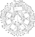
- FIG. 3 is a front view showing a state in which the power circuit unit 23 and the field circuit unit 24 are viewed along the axial direction of the rotation shaft 12 of FIG. 1 is a cross-sectional view taken along the line II of FIG. 3, and
- FIG. 2 is a cross-sectional view taken along the line II-II of FIG.
- the power circuit unit 23 and the field circuit unit 24 are disposed inside the rear bracket 8.
- the power circuit unit 23 and the field circuit unit 24 are disposed around the rotation shaft 12.
- the field circuit unit 24 includes a field circuit unit main body 30 having a flat rectangular parallelepiped shape, and a positive terminal 31, a negative terminal 32, a field terminal 33, and a plurality of terminals protruding from the side surface of the field circuit unit main body 30. And a signal terminal 34.
- the field circuit unit main body 30 is disposed with its thickness direction aligned with the axial direction of the rotating shaft 12.
- the positive terminal 31 is provided on the side close to the rotary shaft 12
- the negative terminal 32 and the field terminal 33 are provided on the side away from the rotary shaft 12.
- Signal terminals 34 are provided on the remaining two side surfaces.
- the power circuit unit 23 is an annular device that surrounds the rotation shaft 12. Also, the power circuit unit 23 includes a plurality of (six in this example) power modules 35, a power interconnection component 36 including power wiring for each of the power modules 35 and the field circuit unit 24, and a field circuit. And an annular heat sink 37 (FIG. 2) on which each of the power modules 35 and the power interconnection component 36 are attached.
- the heat sink 37 is a plate-like member disposed perpendicularly to the axis of the rotation shaft 12 as shown in FIG. Further, the heat sink 37 is supported by the rear bracket 8 so as to surround the rotation shaft 12.
- the surface on the side opposite to the rotor core 13 of the heat sink 37 is a common mounting surface 37 a to which the field circuit unit 24, each power module 35 and the power interconnection component 36 are attached.
- the mounting surface 37 a of the heat sink 37 is a flat surface perpendicular to the axis of the rotating shaft 12.
- Cooling fins 37 b are provided on the surface of the heat sink 37 on the side of the rotor core 13. The heat from the field circuit unit 24, each power module 35 and the power interconnection component 36 is dissipated to the outside air through the heat sink 37 and the fins 37b.
- the power interconnection component 36 is provided with a plurality of openings 38 in which the field circuit unit 24 or each power module 35 is disposed.
- the field circuit unit 24 and the power modules 35 are mounted on the mounting surface 37 a of the heat sink 37 in a state of being disposed in the opening 38. Therefore, the power interconnection component 36 is disposed so as not to overlap the respective regions of the field circuit portion 24 and the respective power modules 35 when the power circuit portion 23 is viewed along the axial direction of the rotating shaft 12. ing. That is, when the power interconnection part 36 looks at the power circuit part 23 along the axial direction of the rotating shaft 12, the field of the power interconnection part 36 does not overlap any of the field circuit part 24 and each power module 35.
- the circuit portion 24 and the power modules 35 are disposed out of the respective regions.
- the field circuit unit 24 and the power modules 35 are arranged at intervals in the circumferential direction of the rotation shaft 12 so as to surround the periphery of the rotation shaft 12.
- Each power module 35 includes a switching element (for example, a power transistor, MOSFET or IGBT), a module body 39 having a flat rectangular shape, and a positive terminal 40, a negative terminal 41, and an AC terminal 42 protruding from the module body 39, respectively. And a plurality of signal terminals 43.
- the power circuit unit 23 converts electric power between electric power and alternating current by repeating ON / OFF switching operation by a switching element.
- the module body 39 is manufactured by integrating the switching element with the insulating resin by insert molding.
- the module main body 39 is disposed with its thickness direction aligned with the axial direction of the rotary shaft 12.
- the positive terminal 40 is provided on the side close to the rotary shaft 12
- the negative terminal 41 and the AC terminal 42 are provided on the side away from the rotary shaft 12
- Each signal terminal 43 is provided on one side.
- the power interconnection component 36 includes a plurality of positive bus bars 44, a plurality of negative bus bars 45, an armature connection terminal 46, a plurality of field connection terminals 47, a positive bus bar 44, and a negative bus bar 45 as a plurality of conductors. And an insulator 48 which is an insulating resin for holding the armature connection terminal 46 and the field connection terminal 47.
- the positive bus bar 44, the negative bus bar 45, the armature connection terminal 46, and the field connection terminal 47 are integrated with the insulator 48 by insert molding.
- the positive bus bar 44, the negative bus bar 45, the armature connection terminal 46, and the field connection terminal 47 are used as power lines for the power modules 35 and the field circuit section 24, respectively.
- FIG. 4 is a front view showing the positive bus bar 44, the negative bus bar 45, the armature connection terminal 46, and the field connection terminal 47 when the insulator 48 is removed from the power interconnection component 36 of FIG. FIG.
- the positive bus bar 44, the negative bus bar 45, the armature connection terminal 46 and the field connection terminal 47 are connected along the axial direction of the rotary shaft 12 to the power interconnection parts 36. When looking at, they are placed apart from each other.
- the positive bus bar 44 is disposed radially inward of the field circuit unit 24 and the power modules 35.
- the negative bus bar 45, the armature connection terminal 46 and the field connection terminal 47 are disposed at positions radially outward of the field circuit unit 24 and the power modules 35.
- the positive bus bar 44 is provided at an annular portion 49 surrounding the circumference of the rotary shaft 12 and at an annular portion 49, spaced apart from each other, and the positive terminal 40 of each power module 35 and the positive terminal 31 of the field circuit portion 24 are A plurality of positive terminal connection portions 50 individually connected by welding or the like, and a power supply terminal portion 51 provided on the annular portion 49 and electrically connected to the battery are provided.
- Each positive terminal connection portion 50 and the power supply terminal portion 51 project from the annular portion 49 in the axial direction of the rotary shaft 12.
- Each of the positive terminal 40 of each power module 35 and the positive terminal 31 of the field circuit unit 24 extends in parallel to the positive terminal connection unit 50.
- the annular portion 49 is formed by bending a strip-shaped conductor so that the thickness direction is in the radial direction.
- the positive bus bar 44 is manufactured by bending a strip-like conductor (metal plate) provided with each positive terminal connection portion 50 and the power supply terminal portion 51 in a cylindrical shape and connecting the end portions. As shown in FIG. 3, the positive bus bar 44 is integrated with the insulator 48 in a state where each positive terminal connection portion 50 and the power supply terminal portion 51 are exposed from the insulator 48.
- Each negative bus bar 45 is provided on the flat plate portion 52 and the flat plate portion 52, and the negative terminal connection portion 53 to which the negative terminal 41 of each power module 35 or the negative terminal 32 of the field circuit portion 24 is connected by welding, for example. And.
- the negative terminal connection portion 53 protrudes from the flat plate portion 52 in the axial direction of the rotary shaft 12.
- Each of the negative terminal 41 of each power module 35 and the negative terminal 32 of the field circuit section 24 extends in parallel to the negative terminal connection section 53.
- the flat plate portion 52 is provided with a bolt through hole 55 through which a bolt 54 (FIG. 1) for fixing the power circuit portion 23 to the rear bracket 8 is passed.
- the negative bus bar 45 is manufactured by bending a plate-like metal piece.
- the negative bus bar 45 is insulated in a state in which the portion around the bolt through hole 55 (a part of the flat portion 52) and the negative terminal connection portion 53 are exposed from the insulator 48. It is integrated with the body 48.
- the power interconnect components 36 and the heat sink 37 are mechanically fastened together at the rear bracket 8 by bolts 54, as shown in FIG.
- the negative bus bar 45 is grounded to the rear bracket 8 by mechanically fastening a portion around the bolt through hole 55 to the rear bracket 8 with a bolt 54.
- the armature connection terminal 46 is provided on the terminal main body portion 56 electrically connected to the stator winding 11 and the terminal main body portion 56, and AC connected to the AC terminal 42 of the power module 35 by, for example, welding or the like. And a terminal connection portion 57.
- the armature connection terminal 46 is manufactured by bending a plate-like metal piece. Further, the armature connection terminal 46 is integrated with the insulator 48 in a state where a part of the terminal main body portion 56 and the AC terminal connection portion 57 are exposed from the insulator 48.
- the AC terminal 42 of each power module 35 extends parallel to the AC terminal connection 57.
- the field connection terminal 47 is provided on the terminal body 58 electrically connected to the rotor winding 14 via the brush 20 and the slip ring 19, and on the terminal body 58. And a field terminal connection portion 59 connected by welding or the like.
- the field connection terminal 47 is manufactured by bending a plate-like metal piece.
- the field connection terminal 47 is integrated with the insulator 48 in a state where a part of the terminal main body 58 and the field terminal connection portion 59 are exposed from the insulator 48.
- the field terminals 33 of the field circuit portion 24 extend in parallel to the field terminal connection portion 59.
- the insulator 48 is annularly shaped such that the rotation shaft 12 passes through the center.
- the opening 38 is provided in the insulator 48 so as to avoid the positive bus bar 44, the negative bus bar 45, the armature connection terminal 46 and the field connection terminal 47 (the conductors 44, 45, 46 and 47). ing.
- the power interconnect component 36 is mounted to the heat sink 37 with the insulator 48 in contact with the mounting surface 37a of the heat sink 37, as shown in FIG.
- the position where the insulators 48 overlap the respective regions of the respective power modules 35 and the field circuit portion 24 when the power circuit portion 23 is viewed along the direction (radial direction) perpendicular to the axis of the rotating shaft 12 Is located in That is, the insulator 48, each power module 35, and the field circuit unit 24 are disposed on a common plane perpendicular to the axis of the rotating shaft 12.
- the insulator 48 is provided at the radially inner position of the opening 38 to surround the rotary shaft 12, and at the radially outer position of the opening 38.
- the inner wall 60 and the outer wall are formed to be thinner than the respective thicknesses of the outer wall 61, the inner wall 60, and the outer wall 61, which collectively surround the power modules 35 and the field circuit 24.
- a flat wall portion 62 connecting the two.
- the insulator 48 is attached to the heat sink 37, whereby a recess having the mounting surface 37a of the heat sink 37 as a bottom surface is formed.
- the field circuit unit 24 and the power modules 35 are disposed in a recess formed between the inner wall 60 and the outer wall 61.
- the signal relay component 28 is disposed in a recess formed between the inner wall 60 and the outer wall 61 in a state of facing the field circuit unit 24 and each of the power modules 35.
- the signal wiring of the signal relay component 28 is connected to each of the signal terminal 34 of the field circuit unit 24 and the signal terminal 43 of each power module 35.
- the signal relay connector 29 connects the signal wiring of the signal relay component 28 and the control circuit unit 25.
- an insulating filler (for example, resin etc.) 63 is filled in the recess formed between the inner wall portion 60 and the outer wall portion 61. Thereby, the field circuit unit 24, the signal relay component 28 and the power modules 35 are embedded in the filler 63.
- the power circuit unit 23 and the field circuit unit 24 are controlled by the control circuit unit 25 based on information from each of the rotational position detection sensor 18 and the external device.
- each power module 35 of the power circuit unit 23 switching operation is performed under the control of the control circuit unit 25. Thereby, DC power from the battery is converted to AC power.
- the AC power converted by the power circuit unit 23 is supplied to the stator winding 11. As a result, a rotating magnetic field is generated in the stator 4 and the rotor 5 is rotated. The rotation of the rotor 5 rotates the pulleys 17 to start the engine.
- the power interconnection component 36 including the conductors 44, 45 and 46 individually connected to the terminals 40, 41 and 42 of the power modules 35 is arranged along the axial direction of the rotating shaft 12. Since the power circuit unit 23 is disposed so as not to overlap with the respective regions of the respective power modules 35 when looking at the power circuit unit 23, the power circuit unit 23 is viewed along a direction perpendicular to the axis of the rotating shaft 12.
- the power interconnect components 36 may be arranged such that the power interconnect components 36 overlap each power module 35 when it occurs. Thereby, the dimension of the axial direction of the power circuit part 23 can be made small, and the dimension of the axial direction of the rotary electric machine 1 whole can be made small.
- the strength of the insulator 48 itself can be reduced by supporting the insulator 48 with the heat sink 37 having high strength. it can. Thereby, the volume of the insulator 48 can be reduced, and the weight of the power interconnection component 36 can be reduced. Therefore, weight reduction of the rotary electric machine 1 can be achieved.
- the conductors 44 to 47 of the power interconnection component 36 are disposed apart from each other when the power circuit portion 23 is viewed along the axial direction of the rotating shaft 12, they are prevented from shorting to each other. It is possible to easily secure the dielectric strength of the power interconnection component 36. Further, since the conductors 44 to 47 do not overlap in the axial direction of the rotary shaft 12, the axial dimension of the power interconnection component 36 itself can be reduced. Furthermore, since the conductors 44 to 47 do not overlap in the axial direction of the rotary shaft 12, when the conductors 44 to 47 and the insulating resin are integrated by insert molding, an insulator is interposed between the conductors 44 to 47. This eliminates the need and can simplify the shapes of the conductors 44 to 47 and can facilitate the manufacture of the power interconnection component 36.
- the positive bus bar 44 is disposed at a position radially inward of each power module 35 and the negative bus bar 45 is disposed at a position radially outward than each power module 35, The distance to the negative bus bar 45 can be increased. Thereby, the possibility that the positive bus bar 44 and the negative bus bar 45 will be short-circuited by foreign matter, water or the like can be reduced.
- the positive bus bar 44 has the annular portion 49 disposed so as to surround the rotary shaft 12 at a position radially inward of each power module 35, the length of the positive bus bar 44 is shortened. The resistance due to the length of the positive bus bar 44 can be lowered. Therefore, the cross-sectional area of the positive bus bar 44 can be reduced. Further, since the wiring locations from the battery can be concentrated to one place, it is possible to prevent the occurrence of a potential difference in each power module 35, and to make it difficult to cause an error in the current flow to each power module 35. it can.
- the armature connection terminal 46 connected to the AC terminal 42 of the power module 35 is disposed at a position radially outward of the power module 35, the armature connection terminal 46 and the stator winding 11 are disposed. And electrical connection with each other can be facilitated.
- a part of the negative bus bar 45 leaks from the insulator 48, and an exposed portion of the negative bus bar 45 is mechanically fastened to the rear bracket 8 by the bolt 54, thereby grounding the rear bracket 8 Being connected, the ground connection of the negative bus bar 45 to the rear bracket 8 and the attachment of the power interconnection component 36 to the rear bracket 8 can be made by means of the common bolt 54. Thereby, the number of parts can be reduced. Further, since the power interconnection component 36 is mechanically supported by the rear bracket 8, the strength of the power interconnection component 36 itself can be lowered, and the weight reduction of the power circuit portion 23 can be achieved.
- the filler 63 is filled in the recess formed between the inner wall 60 and the outer wall 61 included in the insulator 48, and the field circuit 24, the signal relay component 28, and the power modules 35 are filled. Since it is embedded in the material 63, it is possible to improve the environmental resistance and the insulation resistance of the field circuit unit 24, the signal relay component 28 and the power modules 35, respectively.
- annular portion 49 is formed by bending the strip-shaped conductor so that the thickness direction is in the radial direction, the positive portion when the power interconnection component 36 is viewed along the axial direction of the rotating shaft 12
- the area of the bus bar 44 can be reduced, and the area of the field circuit unit 24 and the power modules 35 in contact with the heat sink 37 can be increased. Thereby, the temperature rise of each of the field circuit unit 24 and each power module 35 can be suppressed.
- the welding tool can be positive terminal from the axial direction of the rotary shaft 12. It can be easily brought close to the connection portion 50, and welding between the positive terminals 31, 40 and the positive terminal connection portion 50 can be facilitated.
- the welding tool can be a negative terminal from the axial direction of the rotary shaft 12. It can be easily brought close to the connection portion 53, and welding between the negative terminals 32, 41 and the negative terminal connection portion 53 can be facilitated.
- the armature connection terminal 46 has an AC terminal connection portion 57 extending in parallel with the AC terminal 42 along the axial direction of the rotation shaft 12, and the field connection terminal 47 extends along the axial direction of the rotation shaft 12. Since the field terminal connection portion 59 extends parallel to the field terminal 33, the welding tool can be easily attached to the AC terminal connection portion 57 and the field terminal connection portion 59 from the axial direction of the rotary shaft 12. The welding between the AC terminal 42 and the AC terminal connection portion 57 and the welding between the field terminal 33 and the field terminal connection portion 59 can be facilitated.
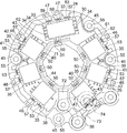
- FIG. 5 is a cross sectional view showing a rear side portion of a rotary electric machine 1 according to a second embodiment of the present invention.
- 6 is a front view showing a state in which the power circuit unit 23 and the field circuit unit 24 are viewed along the axis of the rotary shaft 12 of FIG.
- the positive bus bar 44 includes an annular portion 71 disposed radially inward of the field circuit portion 24 and the power modules 35, and a flat portion 72 projecting radially outward from the annular portion 71.
- the annular portion 71 is disposed to surround the rotation shaft 12.
- the shape of the annular portion 71 is an incomplete annular (tubular) which is partially missing and separated.
- a positive terminal connection portion 50 connected to the positive terminals 31 and 40 protrudes from the annular portion 71 in the axial direction of the rotation shaft 12.
- the flat portion 72 is disposed perpendicular to the axis of the rotating shaft 12. Further, the flat portions 72 are disposed in gaps formed by increasing the distance between the power modules 35 adjacent to each other.
- the positive bus bar 44 is manufactured by bending a band-like metal plate (conductor) provided with a protrusion that becomes the flat portion 72.
- a battery plate 73 is mechanically and electrically connected to the flat portion 72.
- the battery plate 73 is disposed perpendicularly to the axis of the rotating shaft 12.
- the battery plate 73 is fixed to the heat sink 37 together with the power interconnection component 36 by a plurality of bolts (fastening members) 54 with the insulator 48 interposed between the battery plate 73 and the heat sink 37.
- the battery plate 73 is provided with a power terminal portion 74 which protrudes in the axial direction of the rotating shaft 12 and is electrically connected to the battery.
- the shape of the power supply terminal 74 is a bolt.
- the other configuration is the same as that of the first embodiment.
- the power supply terminal portion 74 is provided on the battery plate 73 fixed to the heat sink 37 by the plurality of bolts 54, and the positive bus bar 44 is mechanically and electrically connected to the battery plate 73.
- the power terminal 74 electrically connected to the battery can be firmly fixed to the heat sink 37, so that the rotating electric machine 1 or the breakage of the power circuit 23 due to the vibration of the vehicle on which the rotating electric machine 1 is mounted can be prevented. Can be Thereby, the reliability of the rotating electrical machine 1 can be improved.
- the field circuit unit 24, the power modules 35, and the power interconnection component 36 are attached to the heat sink 37 separate from the rear bracket 8, but Circuitry 24, each power module 35 and power interconnection component 36 may be directly attached.
- a mounting surface perpendicular to the axis of the rotating shaft 12 is formed on the rear bracket 8, and the field circuit unit 24, the power modules 35 and the power interconnection component 36 are common mounting surfaces of the rear bracket 8. Attached to Even in this case, when the power circuit unit 23 is viewed along the axial direction of the rotary shaft 12, the power interconnection component 36 is prevented from overlapping the respective regions of the field circuit unit 24 and the respective power modules 35. It can arrange, and the size of the direction of an axis of rotation electrical machinery 1 can be made small. Further, the function as a heat sink can be added to the rear bracket 8, and the number of parts can be reduced.
Landscapes
- Engineering & Computer Science (AREA)
- Power Engineering (AREA)
- Motor Or Generator Frames (AREA)
Abstract
Description
実施の形態1.
図1は、この発明の実施の形態1による回転電機を示す断面図である。図において、回転電機1は、回転電機本体2と、回転電機本体2に搭載された制御装置3とを有する制御装置一体型回転電機とされている。この例では、回転電機1は交流発電電動機(モータジェネレータ)とされている。
図5は、この発明の実施の形態2による回転電機1のリヤ側の部分を示す断面図である。また、図6は、図5の回転軸12の軸線に沿ってパワー回路部23及び界磁回路部24を見たときの状態を示す正面図である。図において、正のバスバー44は、界磁回路部24及び各パワーモジュール35よりも径方向内側の位置に配置された環状部71と、環状部71から径方向外側へ突出する平坦部72とを有している。
Claims (7)
- 固定子と、回転軸を含み上記固定子に対して回転可能な回転子と、上記固定子及び上記回転子を支持する支持体とを有する回転電機本体、及び
上記回転軸の周囲に配置され、上記回転電機本体から受けた電力又は上記回転電機本体へ供給する電力を交流と直流との間で変換するパワー回路部を有し、上記回転電機本体に設けられた制御装置
を備え、
上記パワー回路部は、スイッチング素子を含むパワーモジュールと、上記パワーモジュールの端子に接続される導体を含む電力相互接続部品とを有し、
上記電力相互接続部品は、上記回転軸の軸線方向に沿って上記パワー回路部を見たときに、上記パワーモジュールの領域に重なることを避けて配置されていることを特徴とする回転電機。 - 上記電力相互接続部品は、上記導体を保持する絶縁体をさらに有し、
上記パワー回路部は、上記パワーモジュール及び上記絶縁体が取り付けられたヒートシンクをさらに有していることを特徴とする請求項1に記載の回転電機。 - 上記電力相互接続部品は、複数の上記導体を有しており、
各上記導体は、上記回転軸の軸線方向に沿って上記パワー回路部を見たときに、互いに離して配置されていることを特徴とする請求項1又は請求項2に記載の回転電機。 - 各上記導体のいずれかは、上記パワーモジュールの正端子に接続される正のバスバーとされ、
各上記導体のいずれかは、上記パワーモジュールの負端子に接続される負のバスバーとされており、
上記正のバスバーは、上記パワーモジュールよりも径方向内側の位置に配置され、
上記負のバスバーは、上記パワーモジュールよりも径方向外側の位置に配置されていることを特徴とする請求項3に記載の回転電機。 - 上記正のバスバーは、上記回転軸を囲むように配置された環状部を有していることを特徴とする請求項4に記載の回転電機。
- 各上記導体のいずれかは、上記パワーモジュールのAC端子に接続され上記AC端子を上記固定子に電気的に接続するための電機子用接続ターミナルとされ、
上記電機子用接続ターミナルは、上記パワーモジュールよりも径方向外側の位置に配置されていることを特徴とする請求項1乃至請求項5のいずれか一項に記載の回転電機。 - 各上記導体は、インサート成形により絶縁体と一体化されており、
上記負のバスバーの一部は、上記絶縁体から露出し、
上記負のバスバーの露出部分は、上記支持体に機械的に締結されることにより、上記支持体にアース接続されていることを特徴とする請求項4乃至請求項6のいずれか一項に記載の回転電機。
Priority Applications (5)
| Application Number | Priority Date | Filing Date | Title |
|---|---|---|---|
| EP11854867.6A EP2662961B1 (en) | 2011-01-06 | 2011-01-06 | Dynamo-electric machine |
| PCT/JP2011/050077 WO2012093476A1 (ja) | 2011-01-06 | 2011-01-06 | 回転電機 |
| CN201180063645.4A CN103299519B (zh) | 2011-01-06 | 2011-01-06 | 旋转电机 |
| JP2012551771A JP5730333B2 (ja) | 2011-01-06 | 2011-01-06 | 回転電機 |
| US13/877,401 US9479032B2 (en) | 2011-01-06 | 2011-01-06 | Rotary electric machine having non-overlapping power interconnecting part |
Applications Claiming Priority (1)
| Application Number | Priority Date | Filing Date | Title |
|---|---|---|---|
| PCT/JP2011/050077 WO2012093476A1 (ja) | 2011-01-06 | 2011-01-06 | 回転電機 |
Publications (1)
| Publication Number | Publication Date |
|---|---|
| WO2012093476A1 true WO2012093476A1 (ja) | 2012-07-12 |
Family
ID=46457344
Family Applications (1)
| Application Number | Title | Priority Date | Filing Date |
|---|---|---|---|
| PCT/JP2011/050077 WO2012093476A1 (ja) | 2011-01-06 | 2011-01-06 | 回転電機 |
Country Status (5)
| Country | Link |
|---|---|
| US (1) | US9479032B2 (ja) |
| EP (1) | EP2662961B1 (ja) |
| JP (1) | JP5730333B2 (ja) |
| CN (1) | CN103299519B (ja) |
| WO (1) | WO2012093476A1 (ja) |
Cited By (2)
| Publication number | Priority date | Publication date | Assignee | Title |
|---|---|---|---|---|
| WO2018079352A1 (ja) * | 2016-10-26 | 2018-05-03 | 三菱電機株式会社 | 制御装置一体型回転電機 |
| CN109110135A (zh) * | 2017-06-23 | 2019-01-01 | 通用电气公司 | 用于飞行器的推进系统 |
Families Citing this family (8)
| Publication number | Priority date | Publication date | Assignee | Title |
|---|---|---|---|---|
| JP2013187998A (ja) * | 2012-03-07 | 2013-09-19 | Nissan Motor Co Ltd | 電力変換装置 |
| CN104620488A (zh) * | 2012-09-19 | 2015-05-13 | 日产自动车株式会社 | 电力变换装置 |
| JP2015119608A (ja) * | 2013-12-20 | 2015-06-25 | 三菱電機株式会社 | 車両用回転電機 |
| FR3018011B1 (fr) * | 2014-02-25 | 2017-08-25 | Valeo Equip Electr Moteur | Ensemble electronique pour machine electrique tournante pour vehicule automobile |
| FR3044842B1 (fr) * | 2015-12-02 | 2021-12-03 | Valeo Systemes De Controle Moteur | Architecture electronique destinee a alimenter une machine electrique pour vehicule automobile |
| FR3057119A1 (fr) * | 2016-10-03 | 2018-04-06 | Valeo Equipements Electriques Moteur | Machine electrique tournante munie d'un connecteur de commande modulable |
| JP2019161774A (ja) * | 2018-03-09 | 2019-09-19 | 株式会社デンソー | 回転電機 |
| US11770045B2 (en) * | 2020-01-06 | 2023-09-26 | Kiryl Nikolaevich CHYKEYUK | Rotary connector module for device forming quasi three-dimentional image |
Citations (1)
| Publication number | Priority date | Publication date | Assignee | Title |
|---|---|---|---|---|
| JP2004274992A (ja) * | 2003-02-18 | 2004-09-30 | Denso Corp | インバータ一体型交流モータ |
Family Cites Families (9)
| Publication number | Priority date | Publication date | Assignee | Title |
|---|---|---|---|---|
| JPH0619281Y2 (ja) * | 1990-07-13 | 1994-05-18 | マブチモーター株式会社 | 交流駆動モータ |
| JP3891559B2 (ja) * | 2002-07-01 | 2007-03-14 | 株式会社デンソー | 多相インバータモジュール |
| WO2004038896A1 (ja) * | 2002-10-28 | 2004-05-06 | Toyota Jidosha Kabushiki Kaisha | 発電電動装置 |
| DE10252315A1 (de) * | 2002-11-11 | 2004-06-03 | Minebea Co., Ltd. | Einrichtung zum Anschliessen elektronischer Bauteile zur Steuerung eines Elektromotors |
| FR2886476B1 (fr) | 2005-05-31 | 2007-07-06 | Valeo Equip Electr Moteur | Piece d'interconnexion de puissance pour machine electrique tournante |
| JP2008136333A (ja) * | 2006-10-30 | 2008-06-12 | Denso Corp | 電力変換装置 |
| JP2009130201A (ja) * | 2007-11-26 | 2009-06-11 | Hitachi Ltd | 半導体装置 |
| JP5624330B2 (ja) * | 2009-06-24 | 2014-11-12 | 株式会社デンソー | モータ |
| US9136740B2 (en) * | 2010-12-13 | 2015-09-15 | Mitsubishi Electric Corporation | Controller-integrated electric rotating machine |
-
2011
- 2011-01-06 WO PCT/JP2011/050077 patent/WO2012093476A1/ja active Application Filing
- 2011-01-06 JP JP2012551771A patent/JP5730333B2/ja active Active
- 2011-01-06 EP EP11854867.6A patent/EP2662961B1/en active Active
- 2011-01-06 CN CN201180063645.4A patent/CN103299519B/zh active Active
- 2011-01-06 US US13/877,401 patent/US9479032B2/en active Active
Patent Citations (1)
| Publication number | Priority date | Publication date | Assignee | Title |
|---|---|---|---|---|
| JP2004274992A (ja) * | 2003-02-18 | 2004-09-30 | Denso Corp | インバータ一体型交流モータ |
Cited By (3)
| Publication number | Priority date | Publication date | Assignee | Title |
|---|---|---|---|---|
| WO2018079352A1 (ja) * | 2016-10-26 | 2018-05-03 | 三菱電機株式会社 | 制御装置一体型回転電機 |
| JP2018074671A (ja) * | 2016-10-26 | 2018-05-10 | 三菱電機株式会社 | 制御装置一体型回転電機 |
| CN109110135A (zh) * | 2017-06-23 | 2019-01-01 | 通用电气公司 | 用于飞行器的推进系统 |
Also Published As
| Publication number | Publication date |
|---|---|
| US9479032B2 (en) | 2016-10-25 |
| JPWO2012093476A1 (ja) | 2014-06-09 |
| EP2662961A4 (en) | 2018-02-07 |
| CN103299519A (zh) | 2013-09-11 |
| CN103299519B (zh) | 2016-05-11 |
| EP2662961A1 (en) | 2013-11-13 |
| JP5730333B2 (ja) | 2015-06-10 |
| US20130187497A1 (en) | 2013-07-25 |
| EP2662961B1 (en) | 2021-05-19 |
Similar Documents
| Publication | Publication Date | Title |
|---|---|---|
| WO2012093476A1 (ja) | 回転電機 | |
| JP4754009B2 (ja) | 車両用回転電機 | |
| JP5456912B2 (ja) | 制御装置一体型回転電機 | |
| JP5202573B2 (ja) | 車両用制御装置一体型回転電機 | |
| JP5774207B2 (ja) | 回転電機 | |
| JP5774208B2 (ja) | 回転電機 | |
| JP5837176B1 (ja) | 制御装置一体型回転電機 | |
| JP5602214B2 (ja) | 制御装置一体型回転電機 | |
| JP5222976B2 (ja) | 回転電機 | |
| US9444312B2 (en) | Rotary electric machine | |
| WO2015063924A1 (ja) | 車両用回転電機 | |
| JP5562395B2 (ja) | 回転電機の組立方法 | |
| JP5701346B2 (ja) | 回転電機 | |
| EP3534510B1 (en) | Rotating electrical machine having integrated control device | |
| JP2014217147A (ja) | 制御装置一体型回転電機 | |
| JP5840282B1 (ja) | 回転電機 | |
| JP7305002B1 (ja) | 制御装置一体型回転電機 | |
| JPWO2018051773A1 (ja) | モータ | |
| US10958140B2 (en) | Motor | |
| JP6345283B1 (ja) | 制御装置一体型回転電機 | |
| CN113054806A (zh) | 用于旋转电机的电子模块 |
Legal Events
| Date | Code | Title | Description |
|---|---|---|---|
| WWE | Wipo information: entry into national phase |
Ref document number: 201180063645.4 Country of ref document: CN |
|
| 121 | Ep: the epo has been informed by wipo that ep was designated in this application |
Ref document number: 11854867 Country of ref document: EP Kind code of ref document: A1 |
|
| WWE | Wipo information: entry into national phase |
Ref document number: 2012551771 Country of ref document: JP |
|
| WWE | Wipo information: entry into national phase |
Ref document number: 13877401 Country of ref document: US |
|
| WWE | Wipo information: entry into national phase |
Ref document number: 2011854867 Country of ref document: EP |
|
| NENP | Non-entry into the national phase |
Ref country code: DE |