WO2012090750A1 - 車体前部の構造 - Google Patents
車体前部の構造 Download PDFInfo
- Publication number
- WO2012090750A1 WO2012090750A1 PCT/JP2011/079324 JP2011079324W WO2012090750A1 WO 2012090750 A1 WO2012090750 A1 WO 2012090750A1 JP 2011079324 W JP2011079324 W JP 2011079324W WO 2012090750 A1 WO2012090750 A1 WO 2012090750A1
- Authority
- WO
- WIPO (PCT)
- Prior art keywords
- horn
- vehicle
- vehicle body
- attached
- pedestrian
- Prior art date
- Legal status (The legal status is an assumption and is not a legal conclusion. Google has not performed a legal analysis and makes no representation as to the accuracy of the status listed.)
- Ceased
Links
Images




Classifications
-
- B—PERFORMING OPERATIONS; TRANSPORTING
- B60—VEHICLES IN GENERAL
- B60Q—ARRANGEMENT OF SIGNALLING OR LIGHTING DEVICES, THE MOUNTING OR SUPPORTING THEREOF OR CIRCUITS THEREFOR, FOR VEHICLES IN GENERAL
- B60Q5/00—Arrangement or adaptation of acoustic signal devices
-
- G—PHYSICS
- G10—MUSICAL INSTRUMENTS; ACOUSTICS
- G10K—SOUND-PRODUCING DEVICES; METHODS OR DEVICES FOR PROTECTING AGAINST, OR FOR DAMPING, NOISE OR OTHER ACOUSTIC WAVES IN GENERAL; ACOUSTICS NOT OTHERWISE PROVIDED FOR
- G10K9/00—Devices in which sound is produced by vibrating a diaphragm or analogous element, e.g. fog horns, vehicle hooters or buzzers
- G10K9/18—Details, e.g. bulbs, pumps, pistons, switches or casings
- G10K9/22—Mountings; Casings
Definitions
- the present invention relates to a structure of a vehicle body front part, and more particularly to a structure for attaching a vehicle horn to a front frame that connects a pair of left and right front side members.
- Patent Document 1 discloses a structure in which a vehicle horn is attached to a front frame.
- a front bumper member extending in the vehicle width direction is attached to the front frame, and the vehicle horn is rearward of the front bumper member in the vehicle front-rear direction. Is located. Therefore, in the structure of Patent Document 1, when the front part of the vehicle body collides with a pedestrian, the front bumper member comes into contact with the pedestrian, so that the possibility that the vehicle horn directly contacts the pedestrian is low.
- the present invention has been made in view of such circumstances, and its purpose is to provide an impact on a pedestrian even when the front of the vehicle collides with a pedestrian and the vehicle horn directly contacts the pedestrian. It is in providing the structure of the vehicle body front part which can suppress this.
- a pair of left and right front side members extending in the vehicle front-rear direction is disposed at the front portion of the vehicle body, and the front end portions of the pair of front side members Are connected by a front frame extending in the vehicle width direction, and the front frame has a horn attached thereto, wherein the horn is connected to the pair of front sides in the front frame. It is arranged in the vicinity of one of the front end portions of the member, and the mounting position of the horn is located behind the front end portion of the front side member in the vehicle front-rear direction.
- the horn is attached to the front frame by a fastening member, and the front end of the fastening member is substantially the same as the front end of the front side member in the vehicle front-rear direction. Arranged at the same position.
- the horn is attached to the front frame in a cantilever manner via a plate member, the horn is attached to one end of the plate member, The other end of the plate member is attached to the front frame.
- a horn wiring protective cover is disposed below the horn, and the horn wiring protective cover is located at a position behind the horn in the vehicle front-rear direction. Installed on the front frame.
- a part of the horn wiring protection cover extends forward of the horn, and the part of the horn wiring protection cover and a part of the horn are It arrange
- a horn mounting bracket is provided at a mounting position of the horn in the front frame, and the horn is connected to the front frame via the horn mounting bracket. Installed on.
- the horn mounting bracket includes a flange portion extending along a vehicle width direction, and the horn is attached to the flange portion.
- the pair of left and right front side members extending in the vehicle front-rear direction is disposed on the vehicle body front portion, and the front end portions of the pair of front side members are arranged in the vehicle width direction.
- the front frame is connected to the front frame, and the front frame has a horn attached thereto.
- the horn is one of the pair of front side members in the front frame. Since the mounting position of the horn is located behind the front end of the front side member in the vehicle front-rear direction, the front of the vehicle body collides with a pedestrian, Even if the horn directly contacts the pedestrian, hard parts etc. at the horn mounting position will not contact the pedestrian, preventing excessive impact on the pedestrian. Door can be.
- the horn is attached to the front frame by a fastening member, and the front end portion of the fastening member is the front end portion of the front side member in the vehicle front-rear direction.
- the fastening member at the mounting position of the horn may come into contact with the pedestrian when the front part of the vehicle collides with the pedestrian. Absent. Therefore, according to this structure, it can prevent that a pedestrian receives an impact with a fastening member.
- the horn is attached to the front frame via the plate member in a cantilever state, and the horn is attached to one end of the plate member. Since the other end of the plate-like member is attached to the front frame, when the vehicle body front part collides with the pedestrian and the vehicle horn directly contacts the pedestrian, the plate-like member is in front of the vehicle. It will bend backwards with respect to the impact from the side. Therefore, since the impact load is absorbed by the plate-like member, the impact on the pedestrian can be suppressed.
- a horn wiring protective cover is disposed below the horn, and the horn wiring protective cover is positioned behind the horn in the vehicle front-rear direction. Because the front part of the vehicle collides with a pedestrian and the horn wiring protective cover directly contacts the pedestrian, hard parts etc. at the mounting position of the horn wiring protective cover are pedestrians. There is no contact. Further, when the horn wiring protective cover directly contacts the pedestrian, the impact on the pedestrian can be suppressed by deforming the specially shaped horn wiring protective cover itself.
- a part of the horn wiring protection cover extends in front of the horn, and the part of the horn wiring protection cover and a part of the horn.
- the horn wiring protection cover and the horn are placed together on the rear side. Will be bent. Therefore, since the impact load is absorbed by both the horn and the horn wiring protective cover, the impact on the pedestrian can be more effectively suppressed.
- a horn mounting bracket is provided at the mounting position of the horn in the front frame, and the horn is connected to the front via the horn mounting bracket. Because it is attached to the front frame, there is no need to change the cross-sectional shape of the front frame or front side member for mounting the vehicle horn, and the horn is maintained while maintaining the rigidity of the front frame and front side member. Can be attached.
- the horn mounting bracket includes a flange portion extending along the vehicle width direction, and the horn is attached to the flange portion.
- the flange portion of the horn mounting bracket bends backward with respect to the impact from the vehicle front side. Therefore, since the impact load is absorbed by the flange portion of the horn mounting bracket, the impact on the pedestrian can be more effectively suppressed.
- FIG. 1 is a perspective view of a front part of a vehicle to which a structure of a front part of a vehicle body according to an embodiment of the present invention is applied. It is a perspective view of the vehicle body front part concerning the embodiment of the present invention. It is an expansion perspective view in the right part of the vehicle body front part concerning the embodiment of the present invention. It is the side view which looked at the right part of the vehicle body front part concerning the embodiment of the present invention from the engine room side. It is the perspective view which looked at the right part of the vehicle body front part concerning the embodiment of the present invention from the engine room side. It is the figure which looked at the right part of the vehicle body front part which concerns on embodiment of this invention from the front, and is the figure which showed the state before attaching a horn.
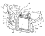
- FIG. 1 is a perspective view of a front part of an automobile to which the structure of the front part of the vehicle body according to the present embodiment is applied.
- FIG. 2 is a perspective view of the front portion of the vehicle body according to the present embodiment
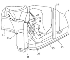
- FIG. 3 is an enlarged perspective view of the right portion of the front portion of the vehicle body according to the present embodiment.
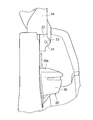
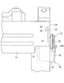
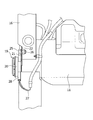
- 4 and 5 are a side view and a perspective view of the right part of the front portion of the vehicle body as viewed from the engine room side.
- FIG. 6 is a view of the right side portion of the front portion of the vehicle body as viewed from the front, and shows a state before the horn is attached.
- FIG. 1 is a perspective view of a front part of an automobile to which the structure of the front part of the vehicle body according to the present embodiment is applied.
- FIG. 2 is a perspective view of the front portion of the vehicle body according to the present embodiment
- FIG. 3 is an enlarged perspective view of the right portion of the front portion of the vehicle body according to the present embodiment
- FIG. 7 is a view of the right part of the front part of the vehicle body as viewed from the front, and shows a state where a horn is attached.
- FIG. 8 is a side view of the right part of the front part of the vehicle body as viewed from the outside in the vehicle width direction
- FIG. 9 is a perspective view of the right part of the front part of the vehicle body as viewed from the engine room side. The state before installation is shown.
- a front bumper 2 extending in the vehicle width direction is disposed at the front of the vehicle body 1. Further, fender panels 3 that extend rearward from the side edges of the front bumper 2 in the vehicle width direction are provided at both ends in the vehicle width direction of the vehicle body 1.
- the front bumper 2 is provided with a front grille 4 along the vehicle width direction, and the front grille 4 is formed in a substantially rectangular shape with the vehicle width direction as a longitudinal direction.
- a pair of headlamps 5 is provided in the vicinity of the side edge of the front grille 4 in the vehicle width direction, and a hood hood 6 covering the engine room is disposed above the front grille 4 so as to be freely opened and closed. Yes.
- FIG. 2 shows a state in which the front bumper 2 and the like in FIG. 1 are removed.
- a pair of left and right front side members 11, 12 extending in the vehicle front-rear direction are disposed at the front portion of the vehicle body 1.
- the front end portions 11 a and 12 a of the pair of front side members 11 and 12 are connected by a front frame 13 that supports vehicle parts such as the radiator 7.
- the front frame 13 includes a pair of an upper member 14 and a lower member 15 that extend in the vehicle width direction, and a pair that extends in the vertical direction and connects both ends of the upper member 14 and the lower member 15 in the vehicle width direction.
- Side braces 16 and 17 and a center brace 18 that extends in the vertical direction and connects the upper member 14 and the lower member 15 in the vehicle width direction central portion.
- the front frame 13 of the present embodiment is configured not to include a front bumper member.
- the front end portions 11 a and 12 a of the pair of front side members 11 and 12 are connected to the side braces 16 and 17 of the front frame 13, respectively.
- the vehicle horn 19 is disposed in the vicinity of the front end 11 a of the right front side member 11 in the right side brace 16 of the front frame 13.
- the horn 19 includes a horn main body 20 including a diaphragm for generating sound, a coil (not shown), and the like.
- the horn main body 20 includes a plate-like member 21 and a horn attachment. It is attached to the right side brace 16 via the bracket 22 for use.
- the horn mounting bracket 22 is disposed below the right side brace 16. As shown in FIG. As shown in FIG. 6, the horn mounting bracket 22 includes a flange portion 23 extending in the vehicle width direction, and the flange portion 23 is provided with an insertion hole 24.
- the horn main body 20 is attached to the flange portion 23 of the horn mounting bracket 22 via a plate-like member 21 in a cantilever state.
- the horn body 20 is attached to one end 21 a of the plate-like member 21, and the other end 21 b of the plate-like member 21 is flanged by a bolt 25 and a nut 26 to the horn mounting bracket 22. Since it is attached to the insertion hole 24 of the part 23, it bends backward with respect to the impact from the vehicle front side, and absorbs an impact load.
- the horn mounting bracket 22 which is the mounting position of the horn 19, is located behind the front end 11 a of the right front side member 11 in the vehicle front-rear direction. is doing.
- the front end portion (end portion on the vehicle front side) 25a of the bolt 25 is disposed at substantially the same position as the front end portion 11a of the right front side member 11 in the vehicle front-rear direction.
- the mounting position of the horn 19 and the tip 25a of the bolt 25 for mounting the horn are configured so as not to be exposed forward of the front side member 11 on the right side.
- a harness 27 is connected to the back surface of the horn body 20 via a connector 28.
- the harness 27 extends downward from the back surface of the horn body 20 and then is wired toward the passenger compartment (not shown).
- a horn wiring protective cover 29 for covering the harness 27 and the connector 28 is disposed below the horn body 20.
- the horn wiring protective cover 29 includes a front wall portion 30 (see FIGS. 5 to 7), a rear wall portion 31 (see FIG. 8), a front wall portion 30 and a rear wall portion. 31 and the bottom wall 33 extending between the lower end of the front wall 30 and the lower end of the rear wall 31 (see FIGS. 5 and 5). 8).
- the horn wiring protective cover 29 is formed in a box shape.
- the side wall portion 32 of the horn wiring protection cover 29 has an upper flange portion 34 extending upward, and the bottom wall portion 33 of the horn wiring protection cover 29 extends downward.
- the lower flange portion 35 is provided.
- the upper flange portion 34 and the lower flange portion 35 are located behind the horn 19 in the vehicle front-rear direction.
- the horn wiring protective cover 29 is attached to the inner side surface 16a of the right side brace 16 by inserting bolts 36, 37 into the upper flange portion 34 and the lower flange portion 35. Yes.
- the horn wiring protective cover 29 is attached to the right side brace 16 at a position rearward of the horn 19 in the vehicle front-rear direction (in this embodiment, a position further rearward than the attachment position of the horn 19). Yes.
- the front wall portion 30 of the horn wiring protection cover 29 is located in front of the horn body 20 in the vehicle front-rear direction.
- the front wall portion 30 of the horn wiring protection cover 29 has an extending portion 30 a extending to the front of the horn main body 20. 30a and a part of the horn body 20 are arranged so as to overlap in the vehicle front-rear direction.
- the mounting position of the horn 19 and the mounting position of the horn wiring protection cover 29 are not exposed to the front side of the front end portion 11a of the front side member 11. It is like that.
- the horn 19 is disposed in the vicinity of the front end portion 11a of the right front side member 11 in the front frame 13, and the mounting position of the horn 19 is Since the front portion of the vehicle body 1 collides with a pedestrian and the vehicle horn 19 directly contacts the pedestrian, the horn 19 is positioned behind the front end 11a of the front side member 11 in the front-rear direction.
- the bolt 25 at the mounting position of the pedestrian is not in contact with the pedestrian, and an excessive impact can be prevented from being applied to the pedestrian.
- the horn body 20 of the horn 19 is attached to the right side brace 16 of the front frame 13 via the plate-like member 21 in a cantilever state.
- the plate member 21 has the horn body 20 of the horn 19 attached to one end 21 a of the plate member 21 and the other end 21 b of the plate member 21 attached to the right side brace 16 of the front frame 13.
- the plate-like member 21 is bent backward with respect to the impact from the front side of the vehicle. Can be suppressed.
- the horn mounting bracket 22 is provided at the mounting position of the horn 19 in the front frame 13, and the horn mounting bracket 22 extends along the vehicle width direction. Since the other end 21b of the plate-like member 21 is attached to the flange portion 23 of the horn mounting bracket 22 by a bolt 25, the side of the front frame 13 is attached for mounting the horn 19. It is not necessary to change the cross-sectional shape of the brace 16 and the front side member 11, and the horn 19 can be attached while maintaining the rigidity of the front frame 13 and the front side member 11.
- the flange portion 23 of the horn mounting bracket 22 is rearward with respect to the impact from the vehicle front side. Will be bent. Therefore, since the impact load is absorbed by the flange portion 23 of the horn mounting bracket 22, the impact on the pedestrian can be more effectively suppressed.
- the horn wiring protection cover 29 is disposed below the horn body 20 of the horn 19, and the horn wiring protection cover 29 is a horn in the vehicle front-rear direction. Since it is attached to the right side brace 16 at a position behind the main body 20 (upper flange portion 34 and lower flange portion 35), the front portion of the vehicle body 1 collides with a pedestrian, and the horn wiring protective cover 29 is Even when the pedestrian directly contacts the pedestrian, the bolts 36 and 37 at the mounting position of the horn wiring protection cover 29 do not contact the pedestrian. Further, when the horn wiring protection cover 29 directly contacts the pedestrian, the box-shaped horn wiring protection cover 29 itself is deformed to absorb the impact load, so that the impact on the pedestrian can be effectively suppressed. .
- the front wall portion 30 of the horn wiring protection cover 29 includes an extension portion 30a extending forward of the horn main body 20, and the extension portion 30a of the horn wiring protection cover 29 and a part of the horn main body 20 are arranged in front and rear of the vehicle. Since they are arranged so as to overlap in the direction, the horn wiring protection cover 29 and the horn main body 20 of the horn 19 are bent backward together. Accordingly, since the impact load is absorbed by both the horn wiring protective cover 29 and the horn 19, the impact on the pedestrian can be more effectively suppressed.
- the horn mounting bracket 22 is attached to the right side brace 16, but the horn mounting bracket 22 may be disposed in the vicinity of the front end portion 11a of the front side member 11, It may be directly attached to the front side member 11.
Landscapes
- Physics & Mathematics (AREA)
- Acoustics & Sound (AREA)
- Engineering & Computer Science (AREA)
- Mechanical Engineering (AREA)
- Body Structure For Vehicles (AREA)
- Fittings On The Vehicle Exterior For Carrying Loads, And Devices For Holding Or Mounting Articles (AREA)
Abstract
本発明は、車両前後方向に延在する左右一対のフロントサイドメンバ11,12が、車体1の前部に配設され、一対のフロントサイドメンバ11,12の前端部11a,12aが、車幅方向に延在する前部フレーム13によって連結され、前部フレーム13には、ホーン19が取付けられている車体前部の構造において、ホーン19は、前部フレーム13において一対のフロントサイドメンバ11,12のいずれか一方の前端部11aの近傍に配置され、ホーン19の取付位置が、車両前後方向においてフロントサイドメンバ11の前端部11aよりも後方に位置している。
Description
本発明は、車体前部の構造に関し、詳しくは、左右一対のフロントサイドメンバを連結する前部フレームに車両用のホーンを取付けるための構造に関する。
従来より、自動車の車体前部には、左右一対のフロントサイドメンバが配設され、一対のフロントサイドメンバは、ラジエータ等の車両部品を支持する前部フレームによって連結されている。特許文献1には、前部フレームに車両用のホーンを取付ける構造が開示されている。
特許文献1の車体前部の構造では、前部フレームには、車幅方向に延在するフロントバンパメンバが取付けられており、車両用のホーンは、車両前後方向においてフロントバンパメンバよりも後方側に位置している。したがって、特許文献1の構造では、車体前部が歩行者と衝突した場合、フロントバンパメンバが歩行者と接触するため、歩行者に車両用のホーンが直接接触する可能性が低かった。
しかしながら、近年、ラジエータ等の車両部品を支持する前部フレームにフロントバンパメンバを設けない車体も提案されている。このような構成では、車体前部が歩行者と衝突した場合、車両用のホーンが直接歩行者に接触し、ホーンを取付けるための締結部材(ボルト)等の硬い部品が歩行者に過度な衝撃を与える場合がある。
本発明は、このような実情に鑑みてなされたものであって、その目的は、車体前部が歩行者と衝突し、車両用ホーンが直接歩行者に接触した場合でも、歩行者にかかる衝撃を抑制することが可能な車体前部の構造を提供することにある。
上記従来技術の有する課題を解決するために、本発明によれば、車両前後方向に延在する左右一対のフロントサイドメンバが、車体前部に配設され、前記一対のフロントサイドメンバの前端部が、車幅方向に延在する前部フレームによって連結され、前記前部フレームには、ホーンが取付けられている車体前部の構造において、前記ホーンは、前記前部フレームにおいて前記一対のフロントサイドメンバのいずれか一方の前端部の近傍に配置され、前記ホーンの取付位置が、車両前後方向において前記フロントサイドメンバの前記前端部よりも後方に位置している。
また、本発明の別の実施態様によれば、前記ホーンは、締結部材により前記前部フレームに取付けられ、前記締結部材の前端部が、車両前後方向において前記フロントサイドメンバの前記前端部と略同じ位置に配置されている。
また、本発明の別の実施態様によれば、前記ホーンは、板状部材を介して前記前部フレームに片持ちの状態で取付けられ、前記板状部材の一端に前記ホーンが取付けられ、前記板状部材の他端が、前記前部フレームに取付けられている。
また、本発明の別の実施態様によれば、前記ホーンの下方には、ホーン配線保護カバーが配置されており、該ホーン配線保護カバーは、車両前後方向において前記ホーンよりも後方の位置で前記前部フレームに取付けられている。
また、本発明の別の実施態様によれば、前記ホーン配線保護カバーの一部は、前記ホーンの前方に延びており、前記ホーン配線保護カバーの前記一部と前記ホーンの一部とが、車両前後方向において重なり合うように配置されている。
また、本発明の別の実施態様によれば、前記前部フレームにおける前記ホーンの取付位置には、ホーン取付用ブラケットが設けられ、前記ホーンは、前記ホーン取付用ブラケットを介して前記前部フレームに取付けられている。
また、本発明の別の実施態様によれば、前記ホーン取付用ブラケットは、車幅方向に沿って延びるフランジ部を備え、前記ホーンが、前記フランジ部に取付けられている。
本発明に係る車体前部の構造によれば、車両前後方向に延在する左右一対のフロントサイドメンバが、車体前部に配設され、前記一対のフロントサイドメンバの前端部が、車幅方向に延在する前部フレームによって連結され、前記前部フレームには、ホーンが取付けられている車体前部の構造において、前記ホーンは、前記前部フレームにおいて前記一対のフロントサイドメンバのいずれか一方の前端部の近傍に配置され、前記ホーンの取付位置が、車両前後方向において前記フロントサイドメンバの前記前端部よりも後方に位置しているので、車体前部が歩行者と衝突し、車両用のホーンが直接歩行者に接触した場合でも、ホーンの取付位置にある硬い部品等が歩行者に接触することがなくなり、歩行者に過度な衝撃がかかることを防ぐことができる。
また、本発明に係る車体前部の構造によれば、前記ホーンは、締結部材により前記前部フレームに取付けられ、前記締結部材の前端部が、車両前後方向において前記フロントサイドメンバの前記前端部と略同じ位置に配置されているので、ホーンを締結部材を用いて取付けた場合でも、車体前部が歩行者と衝突した際にホーンの取付位置にある締結部材が歩行者に接触することがない。したがって、この構成によれば、締結部材によって歩行者に衝撃がかかることを防ぐことができる。
また、本発明に係る車体前部の構造によれば、前記ホーンは、板状部材を介して前記前部フレームに片持ちの状態で取付けられ、前記板状部材の一端に前記ホーンが取付けられ、前記板状部材の他端が、前記前部フレームに取付けられているので、車体前部が歩行者と衝突し、車両用のホーンが直接歩行者に接触した場合、板状部材が車両前方側からの衝撃に対して後方側に撓むことになる。したがって、衝撃荷重が板状部材によって吸収されるので、歩行者に対する衝撃を抑制することができる。
また、本発明に係る車体前部の構造によれば、前記ホーンの下方には、ホーン配線保護カバーが配置されており、該ホーン配線保護カバーは、車両前後方向において前記ホーンよりも後方の位置で前記前部フレームに取付けられているので、車体前部が歩行者と衝突し、ホーン配線保護カバーが直接歩行者に接触した場合、ホーン配線保護カバーの取付位置にある硬い部品等が歩行者に接触することがない。また、ホーン配線保護カバーが直接歩行者に接触した際に、特殊な形状をしたホーン配線保護カバー自体が変形することにより歩行者に対する衝撃を抑制することができる。
また、本発明に係る車体前部の構造によれば、前記ホーン配線保護カバーの一部は、前記ホーンの前方に延びており、前記ホーン配線保護カバーの前記一部と前記ホーンの一部とが、車両前後方向において重なり合うように配置されているので、車体前部が歩行者と衝突し、ホーン配線保護カバーが直接歩行者に接触した場合、ホーン配線保護カバーとホーンとが一緒に後方側に撓むことになる。したがって、衝撃荷重がホーンとホーン配線保護カバーの両方によって吸収されるので、歩行者に対する衝撃をより効果的に抑制することができる。
また、本発明に係る車体前部の構造によれば、前記前部フレームにおける前記ホーンの取付位置には、ホーン取付用ブラケットが設けられ、前記ホーンは、前記ホーン取付用ブラケットを介して前記前部フレームに取付けられているので、車両用のホーンの取付けのために前部フレームやフロントサイドメンバの断面形状を変更する必要がなく、前部フレームやフロントサイドメンバの剛性を維持しながら、ホーンの取付が可能となる。
また、本発明に係る車体前部の構造によれば、前記ホーン取付用ブラケットは、車幅方向に沿って延びるフランジ部を備え、前記ホーンが、前記フランジ部に取付けられているので、車体前部が歩行者と衝突し、車両用のホーンが直接歩行者に接触した場合、ホーン取付用ブラケットのフランジ部が車両前方側からの衝撃に対して後方側に撓むことになる。したがって、衝撃荷重がホーン取付用ブラケットのフランジ部によって吸収されるので、歩行者に対する衝撃をより効果的に抑制することができる。
以下、本発明の実施形態に係る車体前部の構造を、図面を参照しながら説明する。
図1は、本実施形態に係る車体前部の構造が適用される自動車前部の斜視図である。図2は、本実施形態に係る車体前部の斜視図であり、図3は、本実施形態に係る車体前部の右側部分における拡大斜視図である。図4及び図5は、車体前部の右側部分をエンジンルーム側から見た側面図及び斜視図である。図6は、車体前部の右側部分を正面から見た図であり、ホーンを取付ける前の状態を示している。一方、図7は、車体前部の右側部分を正面から見た図であり、ホーンを取付けた状態を示している。図8は、車体前部の右側部分を車幅方向外側から見た側面図であり、図9は、車体前部の右側部分をエンジンルーム側から見た斜視図であり、ホーン配線保護カバーを取付ける前の状態を示している。
図1に示すように、車体1の前部には、車幅方向に延在するフロントバンパ2が配設されている。また、車体1の車幅方向両端部には、フロントバンパ2の車幅方向の側縁部から車両後方に延在するフェンダーパネル3が設けられている。
図1に示すように、フロントバンパ2には、車幅方向に沿ってフロントグリル4が設けられており、フロントグリル4は、車幅方向を長手方向とする略長方形状に形成されている。また、フロントグリル4の車幅方向の側縁部の近傍には、一対のヘッドランプ5が設けられ、フロントグリル4の上方には、エンジンルームを覆うボンネットフード6が開閉自在に配設されている。
図2は、図1のフロントバンパ2等を除いた状態を示している。図2に示すように、車体1の前部には、車両前後方向に延在する左右一対のフロントサイドメンバ11,12が配設されている。一対のフロントサイドメンバ11,12の前端部11a,12aは、ラジエータ7等の車両部品を支持する前部フレーム13によって連結されている。
図2に示すように、前部フレーム13は、車幅方向に延在するアッパメンバ14及びロアメンバ15と、上下方向に延在し且つアッパメンバ14及びロアメンバ15の車幅方向の両端部を連結する一対のサイドブレース16,17と、上下方向に延在し且つアッパメンバ14及びロアメンバ15の車幅方向中央部を連結するセンタブレース18とから構成されている。図2に示すように、本実施形態の前部フレーム13は、フロントバンパメンバを備えていない構成となっている。
本実施形態では、図2に示すように、一対のフロントサイドメンバ11,12の前端部11a,12aは、前部フレーム13のサイドブレース16,17にそれぞれ連結されている。図2及び図3に示すように、車両用のホーン19は、前部フレーム13の右側のサイドブレース16において、右側のフロントサイドメンバ11の前端部11aの近傍に配置されている。図3ないし図5に示すように、ホーン19は、音を発生させるダイヤフラム、コイル(図示せず)等を内蔵したホーン本体20を備えており、ホーン本体20は、板状部材21及びホーン取付用ブラケット22を介して右側のサイドブレース16に取付けられている。
図4及び図5に示すように、ホーン取付用ブラケット22は、右側のサイドブレース16の下方に配設されている。図6に示すように、ホーン取付用ブラケット22は、車幅方向に延在するフランジ部23を備えており、フランジ部23には、挿通孔24が設けられている。
図7に示すように、ホーン本体20は、板状部材21を介してホーン取付用ブラケット22のフランジ部23に片持ちの状態で取付けられている。
図4及び図7に示すように、板状部材21の一端21aには、ホーン本体20が取付けられ、板状部材21の他端21bは、ボルト25及びナット26によりホーン取付用ブラケット22のフランジ部23の挿通孔24に取付けられているので、車両前方側からの衝撃に対して後方側に撓んで、衝撃荷重を吸収するようになっている。
図4及び図7に示すように、板状部材21の一端21aには、ホーン本体20が取付けられ、板状部材21の他端21bは、ボルト25及びナット26によりホーン取付用ブラケット22のフランジ部23の挿通孔24に取付けられているので、車両前方側からの衝撃に対して後方側に撓んで、衝撃荷重を吸収するようになっている。
図4及び図8に示すように、本実施形態の特徴として、ホーン19の取付位置であるホーン取付用ブラケット22は、車両前後方向において右側のフロントサイドメンバ11の前端部11aよりも後方に位置している。加えて、図4に示すように、ボルト25の先端部(車両前方側の端部)25aは、車両前後方向において右側のフロントサイドメンバ11の前端部11aと略同じ位置に配置されている。
すなわち、本実施形態では、ホーン19の取付位置及びホーン取付用のボルト25の先端部25aが、右側のフロントサイドメンバ11よりも前方に露出しないような構成となっている。
すなわち、本実施形態では、ホーン19の取付位置及びホーン取付用のボルト25の先端部25aが、右側のフロントサイドメンバ11よりも前方に露出しないような構成となっている。
また、図9に示すように、ホーン本体20の背面には、ハーネス27がコネクタ28を介して接続されている。ハーネス27は、ホーン本体20の背面から下向きに延在した後、車室(図示せず)側に向かって配線されている。
本実施形態では、図3ないし図8に示すように、ホーン本体20の下方には、ハーネス27及びコネクタ28(図9参照)を覆うためのホーン配線保護カバー29が配設されている。図4ないし図8に示すように、ホーン配線保護カバー29は、前壁部30(図5ないし図7参照)と、後壁部31(図8参照)と、前壁部30と後壁部31との間に延在する側壁部32(図4及び図5参照)と、前壁部30の下端と後壁部31の下端との間に延在する底壁部33(図5及び図8参照)とを備えている。このように、ホーン配線保護カバー29は、ボックス形状で形成されている。
図4及び図5に示すように、ホーン配線保護カバー29の側壁部32は、上方に延在する上側フランジ部34を有し、ホーン配線保護カバー29の底壁部33は、下方に延在する下側フランジ部35を有している。図4に示すように、これら上側フランジ部34及び下側フランジ部35は、車両前後方向においてホーン19よりも後方に位置している。図4及び図5に示すように、ホーン配線保護カバー29は、上側フランジ部34及び下側フランジ部35にボルト36,37を挿通することにより右側のサイドブレース16の内側側面16aに取付けられている。
このように、ホーン配線保護カバー29は、車両前後方向においてホーン19よりも後方の位置(本実施形態では、ホーン19の取付位置よりも更に後方の位置)で右側のサイドブレース16に取付けられている。
このように、ホーン配線保護カバー29は、車両前後方向においてホーン19よりも後方の位置(本実施形態では、ホーン19の取付位置よりも更に後方の位置)で右側のサイドブレース16に取付けられている。
また、図5及び図8に示すように、ホーン配線保護カバー29の前壁部30は、車両前後方向においてホーン本体20よりも前方に位置している。図4ないし図8に示すように、ホーン配線保護カバー29の前壁部30は、ホーン本体20の前方に延出する延出部30aを有しており、ホーン配線保護カバー29の延出部30aとホーン本体20の一部とは、車両前後方向において重なり合うように配置されている。
以上のように、フロントバンパメンバを備えていない車体前部の構造において、ホーン19の取付位置及びホーン配線保護カバー29の取付位置が、フロントサイドメンバ11の前端部11aよりも前方側に露出しないようになっている。
以上のように、フロントバンパメンバを備えていない車体前部の構造において、ホーン19の取付位置及びホーン配線保護カバー29の取付位置が、フロントサイドメンバ11の前端部11aよりも前方側に露出しないようになっている。
このように本実施形態に係る車体前部の構造によれば、ホーン19は、前部フレーム13において右側のフロントサイドメンバ11の前端部11aの近傍に配置され、ホーン19の取付位置が、車両前後方向においてフロントサイドメンバ11の前端部11aよりも後方に位置しているので、車体1の前部が歩行者と衝突し、車両用のホーン19が直接歩行者に接触した場合でも、ホーン19の取付位置にあるボルト25が歩行者に接触することがなくなり、歩行者に過度な衝撃がかかることを防ぐことができる。
また、本実施形態に係る車体前部の構造によれば、ホーン19のホーン本体20は、板状部材21を介して前部フレーム13の右側のサイドブレース16に片持ちの状態で取付けられ、板状部材21は、板状部材21の一端21aにホーン19のホーン本体20が取付けられ、板状部材21の他端21bが、前部フレーム13の右側のサイドブレース16に取付けられているので、車体1の前部が歩行者と衝突し、ホーン19が直接歩行者に接触した場合、板状部材21が、車両前方側からの衝撃に対して後方側に撓むことになり、歩行者に対する衝撃を抑制することができる。
また、本実施形態に係る車体前部の構造によれば、前部フレーム13におけるホーン19の取付位置には、ホーン取付用ブラケット22が設けられ、ホーン取付用ブラケット22は、車幅方向に沿って延びるフランジ部23を備え、板状部材21の他端21bが、ボルト25によりホーン取付用ブラケット22のフランジ部23に取付けられているので、ホーン19の取付けのために前部フレーム13のサイドブレース16やフロントサイドメンバ11の断面形状を変更する必要がなく、前部フレーム13やフロントサイドメンバ11の剛性を維持しながら、ホーン19の取付が可能となる。しかも、車体1の前部が歩行者と衝突し、車両用のホーン19が直接歩行者に接触した場合、ホーン取付用ブラケット22のフランジ部23が、車両前方側からの衝撃に対して後方側に撓むことになる。したがって、衝撃荷重がホーン取付用ブラケット22のフランジ部23によって吸収されるので、歩行者に対する衝撃をより効果的に抑制することができる。
また、本実施形態に係る車体前部の構造によれば、ホーン19のホーン本体20の下方には、ホーン配線保護カバー29が配置されており、ホーン配線保護カバー29は、車両前後方向においてホーン本体20よりも後方の位置(上側フランジ部34及び下側フランジ部35)で右側のサイドブレース16に取付けられているので、車体1の前部が歩行者と衝突し、ホーン配線保護カバー29が直接歩行者に接触した場合でも、ホーン配線保護カバー29の取付位置にあるボルト36,37が歩行者に接触することがない。また、ホーン配線保護カバー29が直接歩行者に接触した際に、ボックス形状のホーン配線保護カバー29自体が変形して衝撃荷重を吸収するので、歩行者に対する衝撃を効果的に抑制することができる。
また、ホーン配線保護カバー29の前壁部30は、ホーン本体20の前方に延びる延出部30aを備え、ホーン配線保護カバー29の延出部30aとホーン本体20の一部とが、車両前後方向において重なり合うように配置されているので、ホーン配線保護カバー29とホーン19のホーン本体20とが一緒に後方側に撓むことになる。したがって、衝撃荷重が、ホーン配線保護カバー29とホーン19の両方によって吸収されるので、歩行者に対する衝撃をより効果的に抑制することができる。
以上、本発明の実施の形態につき述べたが、本発明は既述の実施形態に限定されるものでなく、本発明の技術的思想に基づいて各種の変形及び変更が可能である。
上述の実施形態では、ホーン取付用ブラケット22は、右側のサイドブレース16に取付けられているが、ホーン取付用ブラケット22は、フロントサイドメンバ11の前端部11aの近傍に配置されていればよく、フロントサイドメンバ11に直接取付けられていてもよい。
1 車体
2 フロントバンパ
3 フェンダーパネル
4 フロントグリル
5 ヘッドランプ
6 ボンネットフード
7 ラジエータ
11,12 フロントサイドメンバ
13 前部フレーム
14 アッパメンバ
15 ロアメンバ
16,17 サイドブレース
18 センタブレース
19 ホーン
20 ホーン本体
21 板状部材
22 ホーン取付用ブラケット
23 フランジ部
24 挿通孔
25,36,37 ボルト
26 ナット
27 ハーネス
28 コネクタ
29 ホーン配線保護カバー
30 ホーン配線保護カバーの前壁部
30a 前壁部の延出部
31 ホーン配線保護カバーの後壁部
32 ホーン配線保護カバーの側壁部
33 ホーン配線保護カバーの底壁部
34 上側フランジ部
35 下側フランジ部
2 フロントバンパ
3 フェンダーパネル
4 フロントグリル
5 ヘッドランプ
6 ボンネットフード
7 ラジエータ
11,12 フロントサイドメンバ
13 前部フレーム
14 アッパメンバ
15 ロアメンバ
16,17 サイドブレース
18 センタブレース
19 ホーン
20 ホーン本体
21 板状部材
22 ホーン取付用ブラケット
23 フランジ部
24 挿通孔
25,36,37 ボルト
26 ナット
27 ハーネス
28 コネクタ
29 ホーン配線保護カバー
30 ホーン配線保護カバーの前壁部
30a 前壁部の延出部
31 ホーン配線保護カバーの後壁部
32 ホーン配線保護カバーの側壁部
33 ホーン配線保護カバーの底壁部
34 上側フランジ部
35 下側フランジ部
Claims (7)
- 車両前後方向に延在する左右一対のフロントサイドメンバが、車体前部に配設され、前記一対のフロントサイドメンバの前端部が、車幅方向に延在する前部フレームによって連結され、前記前部フレームには、ホーンが取付けられている車体前部の構造において、
前記ホーンは、前記前部フレームにおいて前記一対のフロントサイドメンバのいずれか一方の前端部の近傍に配置され、前記ホーンの取付位置が、車両前後方向において前記フロントサイドメンバの前記前端部よりも後方に位置していることを特徴とする車体前部の構造。 - 前記ホーンは、締結部材により前記前部フレームに取付けられ、前記締結部材の前端部が、車両前後方向において前記フロントサイドメンバの前記前端部と略同じ位置に配置されていることを特徴とする請求項1に記載の車体前部の構造。
- 前記ホーンは、板状部材を介して前記前部フレームに片持ちの状態で取付けられ、前記板状部材の一端に前記ホーンが取付けられ、前記板状部材の他端が、前記前部フレームに取付けられていることを特徴とする請求項1又は2に記載の車体前部の構造。
- 前記ホーンの下方には、ホーン配線保護カバーが配置されており、該ホーン配線保護カバーは、車両前後方向において前記ホーンよりも後方の位置で前記前部フレームに取付けられていることを特徴とする請求項1ないし3のいずれか一項に記載の車体前部の構造。
- 前記ホーン配線保護カバーの一部は、前記ホーンの前方に延びており、前記ホーン配線保護カバーの前記一部と前記ホーンの一部とが、車両前後方向において重なり合うように配置されていることを特徴とする請求項4に記載の車体前部の構造。
- 前記前部フレームにおける前記ホーンの取付位置には、ホーン取付用ブラケットが設けられ、前記ホーンは、前記ホーン取付用ブラケットを介して前記前部フレームに取付けられていることを特徴とする請求項1ないし4のいずれか一項に記載の車体前部の構造。
- 前記ホーン取付用ブラケットは、車幅方向に沿って延びるフランジ部を備え、前記ホーンが、前記フランジ部に取付けられていることを特徴とする請求項6に記載の車体前部の構造。
Priority Applications (2)
| Application Number | Priority Date | Filing Date | Title |
|---|---|---|---|
| CN201180055645.XA CN103221261B (zh) | 2010-12-28 | 2011-12-19 | 车体前部的结构 |
| JP2012550838A JP5630721B2 (ja) | 2010-12-28 | 2011-12-19 | 車体前部の構造 |
Applications Claiming Priority (2)
| Application Number | Priority Date | Filing Date | Title |
|---|---|---|---|
| JP2010-292614 | 2010-12-28 | ||
| JP2010292614 | 2010-12-28 |
Publications (1)
| Publication Number | Publication Date |
|---|---|
| WO2012090750A1 true WO2012090750A1 (ja) | 2012-07-05 |
Family
ID=46382861
Family Applications (1)
| Application Number | Title | Priority Date | Filing Date |
|---|---|---|---|
| PCT/JP2011/079324 Ceased WO2012090750A1 (ja) | 2010-12-28 | 2011-12-19 | 車体前部の構造 |
Country Status (3)
| Country | Link |
|---|---|
| JP (1) | JP5630721B2 (ja) |
| CN (1) | CN103221261B (ja) |
| WO (1) | WO2012090750A1 (ja) |
Cited By (3)
| Publication number | Priority date | Publication date | Assignee | Title |
|---|---|---|---|---|
| JP2013244925A (ja) * | 2012-05-29 | 2013-12-09 | Suzuki Motor Corp | 車体前部構造 |
| JP2014080173A (ja) * | 2012-09-27 | 2014-05-08 | Daihatsu Motor Co Ltd | 車両のホーン保護構造 |
| FR3110509A1 (fr) * | 2020-05-25 | 2021-11-26 | Psa Automobiles Sa | Châssis d'un véhicule automobile équipé d'un avertisseur sonore fixé à un support monté sur le châssis basculant à un seuil d'effort prédéfini. |
Families Citing this family (6)
| Publication number | Priority date | Publication date | Assignee | Title |
|---|---|---|---|---|
| JP6012799B2 (ja) * | 2015-03-16 | 2016-10-25 | 本田技研工業株式会社 | 車両のホーン取付構造 |
| JP6870473B2 (ja) * | 2017-05-23 | 2021-05-12 | スズキ株式会社 | 車両用内燃機関の冷却構造 |
| CN107226022A (zh) * | 2017-06-08 | 2017-10-03 | 芜湖艾卡汽车技术有限公司 | 一种汽车喇叭控制器 |
| FR3088599B1 (fr) * | 2018-11-15 | 2020-10-30 | Psa Automobiles Sa | Support de montage d'un dispositif d'alarme sonore d'un avas sur la caisse d'un vehicule automobile silencieux |
| JP7260492B2 (ja) * | 2020-01-30 | 2023-04-18 | トヨタ自動車株式会社 | 自動車 |
| CN116745172B (zh) * | 2020-11-05 | 2025-09-19 | 浙江极氪智能科技有限公司 | 一种防盗喇叭总成及车辆 |
Citations (2)
| Publication number | Priority date | Publication date | Assignee | Title |
|---|---|---|---|---|
| JP2007001528A (ja) * | 2005-06-27 | 2007-01-11 | Fuji Heavy Ind Ltd | 自動車のホーン取り付け構造 |
| JP2007055331A (ja) * | 2005-08-23 | 2007-03-08 | Suzuki Motor Corp | 車両用ホーンの振動音低減構造 |
Family Cites Families (4)
| Publication number | Priority date | Publication date | Assignee | Title |
|---|---|---|---|---|
| FR2908695B1 (fr) * | 2006-11-20 | 2009-01-02 | Valeo Systemes Thermiques | Face avant pour vehicule automobile |
| FR2910865B1 (fr) * | 2006-12-28 | 2009-04-03 | Plastic Omnium Cie | Piece d'appui pour systeme d'absorption de chocs destinee a etre montee en bout d'un longeron d'un vehicule automobile |
| JP2009166803A (ja) * | 2008-01-21 | 2009-07-30 | Mazda Motor Corp | 車両用ホーンの配設構造 |
| CN201665252U (zh) * | 2010-01-26 | 2010-12-08 | 重庆长安汽车股份有限公司 | 一种汽车前风窗下横梁盖板总成结构 |
-
2011
- 2011-12-19 WO PCT/JP2011/079324 patent/WO2012090750A1/ja not_active Ceased
- 2011-12-19 CN CN201180055645.XA patent/CN103221261B/zh not_active Expired - Fee Related
- 2011-12-19 JP JP2012550838A patent/JP5630721B2/ja active Active
Patent Citations (2)
| Publication number | Priority date | Publication date | Assignee | Title |
|---|---|---|---|---|
| JP2007001528A (ja) * | 2005-06-27 | 2007-01-11 | Fuji Heavy Ind Ltd | 自動車のホーン取り付け構造 |
| JP2007055331A (ja) * | 2005-08-23 | 2007-03-08 | Suzuki Motor Corp | 車両用ホーンの振動音低減構造 |
Cited By (3)
| Publication number | Priority date | Publication date | Assignee | Title |
|---|---|---|---|---|
| JP2013244925A (ja) * | 2012-05-29 | 2013-12-09 | Suzuki Motor Corp | 車体前部構造 |
| JP2014080173A (ja) * | 2012-09-27 | 2014-05-08 | Daihatsu Motor Co Ltd | 車両のホーン保護構造 |
| FR3110509A1 (fr) * | 2020-05-25 | 2021-11-26 | Psa Automobiles Sa | Châssis d'un véhicule automobile équipé d'un avertisseur sonore fixé à un support monté sur le châssis basculant à un seuil d'effort prédéfini. |
Also Published As
| Publication number | Publication date |
|---|---|
| JP5630721B2 (ja) | 2014-11-26 |
| CN103221261B (zh) | 2015-05-13 |
| JPWO2012090750A1 (ja) | 2014-06-05 |
| CN103221261A (zh) | 2013-07-24 |
Similar Documents
| Publication | Publication Date | Title |
|---|---|---|
| JP5630721B2 (ja) | 車体前部の構造 | |
| JP4853197B2 (ja) | 車両の前部構造 | |
| JP2008265399A (ja) | 自動車の前部構造 | |
| JP6304505B2 (ja) | 車両の側部車体構造 | |
| JP5203764B2 (ja) | 自動車の前部車体構造 | |
| JP2009287950A (ja) | レーダー装置の取付構造 | |
| JP4292171B2 (ja) | 自動車の前部車体構造 | |
| JP2007030535A (ja) | レーダーユニットの取付構造 | |
| JP6799772B2 (ja) | フロントバンパカバー支持構造 | |
| JP5614663B2 (ja) | 車体前部の構造 | |
| JP2007223432A (ja) | 車体前部構造 | |
| JP2014151868A (ja) | 車両前部構造 | |
| JP2019093823A (ja) | カウルトップガーニッシュ支持構造 | |
| JP5688394B2 (ja) | 車体前部構造 | |
| JP2011173568A (ja) | 自動車のカウル構造 | |
| WO2012001800A1 (ja) | 車両のランプ及びフェンダの支持構造 | |
| JP4905678B2 (ja) | 車両前部の車体構造 | |
| JP4843630B2 (ja) | 車両のフロント構造 | |
| JP6459031B2 (ja) | アンダーランプロテクタの取付構造及びアンダーランプロテクタブラケット | |
| JP2001138840A (ja) | バンパ配設部構造 | |
| JP5347613B2 (ja) | 自動車の車体構造 | |
| JP5733043B2 (ja) | リヤバンパカバー支持構造 | |
| JP4669743B2 (ja) | 自動車の前部車体構造 | |
| JP7782680B2 (ja) | 車両前部構造 | |
| JP2022090869A (ja) | 車両前部構造 |
Legal Events
| Date | Code | Title | Description |
|---|---|---|---|
| 121 | Ep: the epo has been informed by wipo that ep was designated in this application |
Ref document number: 11854374 Country of ref document: EP Kind code of ref document: A1 |
|
| ENP | Entry into the national phase |
Ref document number: 2012550838 Country of ref document: JP Kind code of ref document: A |
|
| NENP | Non-entry into the national phase |
Ref country code: DE |
|
| 122 | Ep: pct application non-entry in european phase |
Ref document number: 11854374 Country of ref document: EP Kind code of ref document: A1 |