WO2012090724A1 - タービンスクロール部構造 - Google Patents
タービンスクロール部構造 Download PDFInfo
- Publication number
- WO2012090724A1 WO2012090724A1 PCT/JP2011/079154 JP2011079154W WO2012090724A1 WO 2012090724 A1 WO2012090724 A1 WO 2012090724A1 JP 2011079154 W JP2011079154 W JP 2011079154W WO 2012090724 A1 WO2012090724 A1 WO 2012090724A1
- Authority
- WO
- WIPO (PCT)
- Prior art keywords
- turbine
- tongue
- scroll
- offset
- exhaust gas
- Prior art date
Links
Images


Classifications
-
- F—MECHANICAL ENGINEERING; LIGHTING; HEATING; WEAPONS; BLASTING
- F04—POSITIVE - DISPLACEMENT MACHINES FOR LIQUIDS; PUMPS FOR LIQUIDS OR ELASTIC FLUIDS
- F04D—NON-POSITIVE-DISPLACEMENT PUMPS
- F04D29/00—Details, component parts, or accessories
- F04D29/40—Casings; Connections of working fluid
- F04D29/42—Casings; Connections of working fluid for radial or helico-centrifugal pumps
-
- F—MECHANICAL ENGINEERING; LIGHTING; HEATING; WEAPONS; BLASTING
- F01—MACHINES OR ENGINES IN GENERAL; ENGINE PLANTS IN GENERAL; STEAM ENGINES
- F01D—NON-POSITIVE DISPLACEMENT MACHINES OR ENGINES, e.g. STEAM TURBINES
- F01D9/00—Stators
- F01D9/02—Nozzles; Nozzle boxes; Stator blades; Guide conduits, e.g. individual nozzles
- F01D9/026—Scrolls for radial machines or engines
-
- F—MECHANICAL ENGINEERING; LIGHTING; HEATING; WEAPONS; BLASTING
- F02—COMBUSTION ENGINES; HOT-GAS OR COMBUSTION-PRODUCT ENGINE PLANTS
- F02C—GAS-TURBINE PLANTS; AIR INTAKES FOR JET-PROPULSION PLANTS; CONTROLLING FUEL SUPPLY IN AIR-BREATHING JET-PROPULSION PLANTS
- F02C6/00—Plural gas-turbine plants; Combinations of gas-turbine plants with other apparatus; Adaptations of gas- turbine plants for special use
- F02C6/04—Gas-turbine plants providing heated or pressurised working fluid for other apparatus, e.g. without mechanical power output
- F02C6/10—Gas-turbine plants providing heated or pressurised working fluid for other apparatus, e.g. without mechanical power output supplying working fluid to a user, e.g. a chemical process, which returns working fluid to a turbine of the plant
- F02C6/12—Turbochargers, i.e. plants for augmenting mechanical power output of internal-combustion piston engines by increase of charge pressure
-
- F—MECHANICAL ENGINEERING; LIGHTING; HEATING; WEAPONS; BLASTING
- F05—INDEXING SCHEMES RELATING TO ENGINES OR PUMPS IN VARIOUS SUBCLASSES OF CLASSES F01-F04
- F05D—INDEXING SCHEME FOR ASPECTS RELATING TO NON-POSITIVE-DISPLACEMENT MACHINES OR ENGINES, GAS-TURBINES OR JET-PROPULSION PLANTS
- F05D2220/00—Application
- F05D2220/40—Application in turbochargers
Definitions
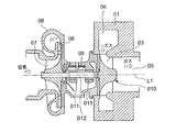
- FIG. 6 is Japanese Patent Laid-Open No. 2003-120303 (Patent Document 1) showing an example of a supercharger using such a radial turbine as a conventional technique.
- 01 is a turbine housing
- 04 is a spiral scroll portion formed in the turbine housing 01
- 05 is an exhaust gas exhaust passage formed in the inner periphery of the turbine housing 01
- 06 is a compressor housing
- 09 is a turbine housing 01.
- 010 is a turbine wheel, and a plurality of turbine blades 03 are fixed to the outer peripheral portion at equal intervals in the circumferential direction.
- Reference numeral 07 denotes a compressor impeller
- 08 denotes a diffuser provided at an air outlet of the compressor impeller 07
- 012 denotes a rotor shaft connecting the turbine wheel 010 and the compressor impeller 07.
- Reference numeral 011 denotes a pair of bearings that are attached to the bearing housing 09 and support the rotor shaft 012.
- L1 is the rotational axis of the turbine wheel 010, the compressor impeller, and the rotor shaft 012. *
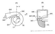
- FIG. 7A shows a schematic cross-sectional configuration diagram in the direction perpendicular to the axis L1 of the rotor shaft 012 in the vicinity of the tongue formed on the inner periphery of the exhaust gas inlet of the radial turbine of Patent Document 1, and FIG.
- the W arrow directional view of (A) is shown.
- 04 is a scroll portion
- 044 is an exhaust gas introduction port
- 045 is a flow passage 046 of a connection portion where exhaust gas from the exhaust gas introduction port 044 passes through the flow passage 046 and is introduced into the scroll portion 04.
- a tongue portion is formed to partition the blade side passage 047 flowing into the blade. Then, as shown in FIG.
- the tongue portion 045 receives exhaust gas heat from the flow path 046 side and the moving blade side passage 047 side, while the heat accumulated in the tongue portion 045 is represented by an arrow Z.
- the heat dissipation path is so narrow that the heat dissipation efficiency is not good. Accordingly, the temperature of the tongue 045 may be 800 to 900 ° C.
- the high-temperature exhaust gas from the engine passes through the flow path 046 and flows out to the moving blade side passage 047 while circling the scroll portion 04 along the spiral portion.
- the tongue portion 045 is exposed to the high temperature exhaust gas from both sides of the flow path 046 and the rotor blade side passage 047, and the heat radiation path of the tongue portion 045 is only in the Z direction [see FIG.
- the tongue portion 045 is likely to be fatigued due to surface oxidation or thermal stress.
- an expensive material for example, austenitic cast steel, ferritic cast steel, etc. having good oxidation resistance and fatigue resistance at high temperatures is used as the material of the turbine housing 01, which causes an increase in cost.
- the present invention was made to solve such problems, and by increasing the outside air exposed surface area outside the connecting portion (tongue portion) of the turbine housing and increasing the amount of heat released from the portion,
- the object is to reduce the cost by suppressing the heat accumulated in the tongue and lowering the heat-resistant grade of the material used for the portion.
- the present invention allows exhaust gas to flow in a radial direction from a spiral scroll portion formed in a turbine housing to a moving blade of the scroll portion so as to act on the moving blade.
- the flow path of the connection portion from the exhaust gas inlet to the turbine housing to the scroll portion is offset along the axis of the rotation axis of the turbine rotor, and the flow that flows into the flow path and the rotor blades by the offset.
- a wall surface exposed to the outside air is formed in the vicinity of the tongue portion that partitions the wing-side passage, and heat radiation near the tongue portion is performed by the wall surface.
- the axial length of the wall surface is changed in accordance with the offset amount, and the offset amount of the flow path is decreased toward the tip of the tongue portion.
- the flow loss of the exhaust gas can be suppressed by reducing the offset at the front end of the tongue and reducing the step at the entrance of the scroll part.
- the offset of the flow path is formed by deforming only the spiral inner peripheral side.
- the amount of deformation on the outer peripheral side of the scroll portion can be suppressed to prevent deterioration in the mountability to the engine, and the heat radiation of the tongue portion can be promoted.
- the offset is reduced from a portion of about 45 degrees toward the exhaust gas inflow side with the axis as a center, with reference to a line connecting the axis of the turbine scroll and the tip of the tongue. It is preferable that the offset is set to zero at the tip of the tongue.
- the range of the offset is decreased from a portion of approximately 45 degrees toward the exhaust gas inflow side with the axis at the center so that the offset becomes zero at the tip of the tongue, thereby allowing the exhaust gas flow.
- the direction in which the gas is guided is determined, and the flow loss of the exhaust gas can be suppressed.
- FIG. 3 is a cross-sectional view in the direction perpendicular to the turbine rotor axis of the tongue according to the first embodiment of the present invention.
- A) is a schematic structure figure of the exhaust gas distribution space part of the scroll part which concerns on 2nd Embodiment of this invention,
- B) is K section schematic sectional shape figure of (A),
- C) is M part of (A).
- a schematic cross-sectional shape figure and (D) show the N section schematic cross-sectional shape figure of (A).
- the image figure of the cross-sectional shape change of the exhaust gas distribution space part of the scroll part which concerns on 2nd Embodiment of this invention is shown.
- (A) is schematic structure figure of exhaust gas distribution space part of scroll part concerning 3rd Embodiment of this invention
- (B) is Q part schematic sectional shape figure of (A)
- C) is R part of (A).
- a schematic cross-sectional shape figure and (D) show the S section schematic cross-sectional shape figure of (A). Sectional drawing which follows the rotating shaft line of the supercharger using the radial turbine to which this invention is applied is shown.
- (A) is a cross-sectional view perpendicular to the turbine rotor axis of the tongue in the prior art
- (B) is a view taken in the direction of arrow W in (A).
- FIG. 6 showing the overall structure of a turbocharger using a radial turbine to which the present invention is applied, 01 is a turbine housing, 04 is a spiral scroll portion formed in the turbine housing 01, and 05 is a turbine housing 01.
- An exhaust gas exhaust passage formed in the inner periphery, 06 is a compressor housing, 09 is a turbine housing 01, and a bearing housing connecting the compressor housing 06.
- Reference numeral 010 denotes a turbine wheel, and a plurality of turbine blades 03 are fixed to the outer peripheral portion at equal intervals in the circumferential direction.
- Reference numeral 07 denotes a compressor impeller
- 08 denotes a diffuser provided at an air outlet of the compressor impeller 07
- 012 denotes a rotor shaft connecting the turbine wheel 010 and the compressor impeller 07.
- Reference numeral 011 denotes a pair of bearings attached to the bearing housing 09 and supporting the rotor shaft 12.
- L1 is a turbine wheel 010, a compressor impeller, and a rotor shaft 012 Is the axis of rotation.
- exhaust gas from an internal combustion engine enters the scroll 04 from the exhaust gas inlet, and rotates around the spiral of the scroll portion 04 and the outer periphery of the plurality of turbine rotor blades 03. It flows into the turbine rotor blade 03 from the side inlet end face, flows in the radial direction toward the center side of the turbine wheel 010, performs expansion work on the turbine wheel 010, flows in the axial direction, and is discharged from the exhaust gas outlet passage 05.
- the basic configuration of the turbocharger with a radial turbine is the same as that of the conventional technology.
- the shape of the scroll is improved.
- FIG. 1A is a cross-sectional view perpendicular to the turbine rotor axis of the tongue portion according to the first embodiment of the present invention
- FIG. 1B is a view of the scroll portion and the rotation axis of the turbine rotor as viewed from the arrow G in FIG.
- Reference numeral 3 denotes a flow path formed by the turbine housing 5 that allows the exhaust gas from the exhaust gas inlet to flow into the scroll portion 1.
- Reference numeral 1 denotes a scroll portion formed by a turbine housing 5 which is formed in a spiral shape and converts the exhaust gas flowing in from the flow path 3 into a spiral flow and ejects the exhaust gas toward the rotor blade 6 through the rotor blade side passage 4.
- Reference numeral 2 denotes a connecting portion between the flow path 3 and the scroll portion 1, which is a tongue portion that partitions the moving blade side passage 4.
- the flow path 3 has a structure that is deformed by an offset amount H along the axis L1 of the rotating shaft of the turbine rotor (rotor shaft in FIG. 6). As shown in FIG. 1B, the exhaust gas passage sectional area of the flow path 3 cannot be changed (changing the passage sectional area changes the performance of the turbocharger). Accordingly, the cross-sectional shape of the flow path 3 formed by the turbine housing 5 is maintained in a state that is offset from the broken line portion to the solid line portion along the axis L1, and accordingly, the tongue portion 2 is also offset.
- the outer wall portion of the turbine housing 5 where the tongue portion 2 is located is formed with a rotor blade side passage outer peripheral wall surface 21 exposed to the outside air, and a scroll side inner peripheral wall surface 22 is formed on the inner peripheral side of the scroll portion 1.
- the heat accumulated in the part 2 is easily dissipated. Therefore, the amount of heat accumulated in the tongue 2 is efficiently radiated from the entire turbine housing 5 in addition to the heat radiated from the rotor blade side passage outer peripheral wall surface 21 and the scroll side inner peripheral wall surface 22.
- FIG. 2 shows a cross section of the tongue 2 in a direction perpendicular to the axis L1 of the rotating shaft of the turbine rotor.
- the tongue 2 is inclined approximately 45 degrees toward the base end side (exhaust gas inlet side) of the tongue 2 around the axis L1 with reference to a reference line L2 connecting the axis L1 and the leading edge 23 of the tongue 2.
- a notch P1 having a length F from the tip edge 23 of the tongue 2 is provided up to a portion that intersects the line. Exhaust gas flows from the notch P ⁇ b> 1 to the rotor blade side passage 4. This is to reduce the amount of heat accumulated in the tongue 2 by reducing the portion of the tongue 2 exposed to the exhaust gas.
- the reason why the position of the notch length F of the tongue 2 is set to 45 degrees is that the thickness of the portion of the tongue 2 is approximately twice the thickness of the tip edge 23, and the heat to the entire turbine housing 5 is increased. The conduction increases and the heat dissipation efficiency of the tongue 2 is improved.
- the width of the notch may be determined arbitrarily. However, if the notch is made larger, the exhaust gas flowing from the flow path 3 to the rotor blade side passage 4 increases, and the performance of the turbocharger decreases. On the other hand, if it is too small, the amount of heat stored in the tongue 2 will increase and the temperature rise will increase. However, since the exposed surfaces 21 and 22 become large, the temperature rise is suppressed as compared with the conventional case. Therefore, the offset amount H may be determined so as to meet the specification status (required performance) of the turbocharger. As a result, the heat resistance grade of the material amount of the turbine housing 5 formed integrally with the tongue portion 2 can be lowered. As an example of the material, an expensive material such as austenitic cast steel or ferritic cast steel has been used conventionally, but it can be replaced with ferritic cast iron or the like.
- the heat radiation area of the outer wall portion of the turbine housing 5 where the tongue portion 2 is located is increased by offsetting the flow path 3 of the connecting portion along the axis L1, so that heat is radiated from the portion.
- the cost can be reduced by lowering the heat resistance grade of the material used for the turbine housing 5.
- the provision of the notch 23 has an effect of suppressing the amount of heat received by the tongue 2.
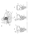
- FIG. 3 (A) is a schematic structural diagram of a space part through which the exhaust gas of the scroll part according to the second embodiment of the present invention flows, and (B), (C) and (D) are views of T in FIG. 3 (A).
- the schematic structure figure of the turbine housing 5 of the offset state in the tongue part 8 of each position of K, M, and N is shown.
- Reference numeral 7 denotes a flow path formed by the turbine housing 5 that allows the exhaust gas from the exhaust gas inlet to flow into the scroll portion 1.
- Reference numeral 8 denotes a connecting portion between the flow path 3 and the scroll portion 1, which is a tongue portion that partitions the moving blade side passage 4.
- the tongue portion 8 gives an offset amount E to the moving blade side passage 4 along the axis L1 of the rotating shaft of the turbine rotor (rotor shaft in FIG. 6).
- the offset amount E is decreased from the side toward the tip edge 81, and the tip edge 81 has an offset of 0 (zero).
- FIGS. 3B, 3 ⁇ / b> C, and 3 ⁇ / b> D the exhaust gas passage cross-sectional area of the flow passage 3 cannot be changed. (A change in passage cross-sectional area changes the performance of the turbocharger).
- the cross-sectional shape of the flow path 3 formed by the turbine housing 5 is maintained in a state where the offset amount E is set from the broken line portion to the solid line portion along the axis L1 while being maintained.
- the offset amount E1 and the M cross-section offset amount E2 a state of E1> E2 is formed, and the offset amount is zero in the N cross-section.
- the width of the notch P2 formed in the tongue 8 is smooth from the base end side position of the tongue 2 having the notch length F toward the tip edge 81 of the tongue 2 in FIG.
- the tip edge 81 is the same as the width of the rotor blade side passage 4.
- variety of the notch part P2 of FIG.3 (B), (C) and (D) is large in order of PK ⁇ PM ⁇ PN.
- FIG. 4 shows an image diagram of the cross-sectional shape change of the exhaust gas circulation space portion of the scroll portion according to the second embodiment.
- the K cross section represents FIG. 3 (B)
- the M cross section represents FIG. 3 (C)
- the N cross section represents FIG. 3 (D)
- the width GW represents a portion parallel to the axis L1. It corresponds to the side 51 of the outer peripheral portion.
- GH is the length of the axis L1 in the radial direction, and has a shape including the rotor blade side passage 4 from the outer peripheral portion of the scroll portion 1.
- the K cross-section offset amount E1 is also the largest, followed by the M cross-section offset amount E2, and the N cross-section has an offset amount of 0 (zero).
- the change state of the offset state in the tongue portion 8 is described at three positions.
- the change state of the offset amount E (E1, E2) may be changed smoothly or stepwise.
- the step at the entrance of the scroll part can be removed, so that the flow loss of the exhaust gas flowing inside is reduced, and the performance of the turbocharger can be maintained.
- the surface of the turbine housing 5 becomes wavy, the conduction heat dissipation area from the tongue 8 increases, and the temperature rise of the tongue 8 is suppressed.
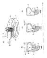
- FIG. 5 (A) is a schematic structural diagram of the space part through which the exhaust gas in the scroll part circulates, and (B), (C) and (D) are the positions of Q, R and S in the direction of the arrow U in FIG.
- the schematic structural drawing of the turbine housing 5 of the offset state in the tongue part 8 is shown.
- Reference numeral 9 denotes a flow path formed by the turbine housing 5 that allows the exhaust gas from the exhaust gas inlet to flow into the scroll portion 1.
- Reference numeral 8 denotes a connecting portion between the flow path 3 and the scroll portion 1, which is a tongue portion that partitions the moving blade side passage 4.
- the tongue portion 8 is offset from the moving blade side passage 4 by an offset amount J along the axis L1 of the rotating shaft of the turbine rotor (rotor shaft in FIG. 6).
- the offset amount J is reduced from the side toward the tip edge 81, and the tip edge 81 has a structure with an offset of zero.
- FIGS. 5B, 5C, and 5D in the present embodiment, the position of the outer peripheral portion 91 and the width V of the channel 9 are not changed, and the tongue portion is not changed. Only the portion 8 and the inner peripheral side wall of the scroll portion 1 are offset.
- the offset portion is changed from the general cross-sectional shape shown by the broken line to the shape of the solid line. It has changed. Accordingly, the cross-sectional area of the flow path 7 formed by the turbine housing 5 is maintained in the shape of the offset amount J (J1, J2) from the broken line portion to the solid line portion along the axis L1. Between the offset amount J1 of the Q cross section and the offset amount J2 of the R cross section, J1> J2 is formed, and the offset amount is 0 in the S cross section. The width of the notch P3 in FIGS.
- the width of the notch P2 formed in the tongue 8 is as shown in FIG. 3A from the base end side (exhaust gas inlet side) position of the tongue 2 having the notch length F to the tip of the tongue 2. It expands smoothly toward the edge 81, and the tip edge 81 has the same width as the rotor blade side passage 4.
- the operational effects of the present embodiment suppress the amount of deformation on the outer peripheral side of the scroll portion, prevent deterioration of mountability to the engine, and promote heat dissipation of the tongue portion. be able to.
- the turbine rotor In order to improve the output of the internal combustion engine, it is used in an internal combustion engine or the like, so that the turbine rotor is rotationally driven by flowing in a radial direction from a spiral scroll portion and then flowing in the rear axis direction after acting on the moving blade. It is good to use for the radial turbine comprised in this.
Abstract
ラジアルタービンのタービンスクロール部構造のおいて、タービンハウジング5への排ガス導入口からスクロール部1への接続部の流路3をタービンロータの回転軸の軸線L1に沿って、オフセットHさせると共に、流路3と動翼6へ流入する動翼側通路4とを仕切る舌部2に流路3から動翼側通路4へ排ガスが流れる切欠き部Pを配設したことを特徴とする。
Description
本発明は、内燃機関の過給機(排気ターボチャージャ)に用いられ、排ガスを渦巻状のスクロール部からタービンロータの動翼へと半径方向に流入させて、該動翼に作用させた後、軸方向に流出させることにより、該タービンロータを回転駆動させるように構成されたラジアルタービンの排ガス流路を形成するスクロール部構造に関する。
自動車の内燃機関等に用いられる過給機(排気ターボチャージャ)には、排ガスをタービンハウジング内に形成された渦巻状のスクロール部から該スクロール部の内側に位置するタービンロータの動翼へと半径方向に流入させて該動翼に作用させた後軸方向に流出させることにより、タービンロータを回転駆動させるように構成されたラジアルタービンが多く採用されている。
図6は従来技術であるかかるラジアルタービンを用いた過給機の一例を示す特開2003-120303号公報(特許文献1)である。図において01はタービンハウジング、04はタービンハウジング01内に形成された渦巻状のスクロール部、05はタービンハウジング01の内周に形成された排ガス排出口通路、06はコンプレッサハウジング、09はタービンハウジング01及び、コンプレッサハウジング06を連結する軸受ハウジングである。
図6は従来技術であるかかるラジアルタービンを用いた過給機の一例を示す特開2003-120303号公報(特許文献1)である。図において01はタービンハウジング、04はタービンハウジング01内に形成された渦巻状のスクロール部、05はタービンハウジング01の内周に形成された排ガス排出口通路、06はコンプレッサハウジング、09はタービンハウジング01及び、コンプレッサハウジング06を連結する軸受ハウジングである。
010はタービンホイールで外周部に複数のタービン動翼03が円周方向等間隔に固着されている。07はコンプレッサインペラ、08はコンプレッサインペラ07の空気出口に設けられたディフューザ、012はタービンホイール010とコンプレッサインペラ07とを連結するロータシャフトである。011は軸受ハウジング09に取付けられてロータシャフト012を支軸する一対の軸受である。L1はタービンホイール010、コンプレッサインペラ及び、ロータシャフト012の回転軸心である。
そして、ラジアルタービンを備えた過給機において、内燃機関(図示省略)からの排ガスはスクロール部04に入り、スクロール部04の渦巻状に沿って周回しながらタービン動翼03外周側入口端面からタービン動翼03に流入して、タービンホイール010の中心側に向かい半径方向に流れて、タービンホイール010に膨張仕事をなした後に、ロータシャフト012の軸線L1方向に流出して、排ガス出口通路05から過給機外に送出される。
図7(A)は特許文献1のラジアルタービンの排ガス入口内周に形成される舌部近傍で、ロータシャフト012の軸線L1に対し直角方向の断面概略構成図を示し、(B)は図7(A)のW矢視図を示す。
図7(A)において04はスクロール部、044は排ガス導入口、045は排ガス導入口044からの排ガスが流路046を通過して、スクロール部04部へ導入される接続部の流路046と動翼へ流入する動翼側通路047とを仕切る舌部が形成されている。
そして、(B)図に示すように、舌部045は排ガス熱を流路046側及び動翼側通路047側から受けることになり、一方で、舌部045に蓄積された熱は矢印Zで表すように放熱経路が狭く放熱効率がよくない。
従って、舌部045の温度は800~900℃に成ることがある。
図7(A)において04はスクロール部、044は排ガス導入口、045は排ガス導入口044からの排ガスが流路046を通過して、スクロール部04部へ導入される接続部の流路046と動翼へ流入する動翼側通路047とを仕切る舌部が形成されている。
そして、(B)図に示すように、舌部045は排ガス熱を流路046側及び動翼側通路047側から受けることになり、一方で、舌部045に蓄積された熱は矢印Zで表すように放熱経路が狭く放熱効率がよくない。
従って、舌部045の温度は800~900℃に成ることがある。
かかる、ラジアルタービンにおいて、エンジンからの高温排ガスは流路046を通過して、スクロール部04を渦巻部に沿って周回しながら動翼側通路047へ流出していく。
このため、舌部045は流路046及び、動翼側通路047の両側から高温排ガスに曝され、舌部045の放熱経路はZ方向〔図7(A)参照〕しかないので、熱が蓄積し易く高温になり、舌部045は表面酸化や、熱応力が原因で疲労損傷が発生しやすくなる。
その対応策として、タービンハウジング01の材料として高温での耐酸化性や耐疲労特性のよい高価な材料(例えばオーステナイト鋳鋼、フェライト鋳鋼等)が使用されておりコスト増加の要因となっている。
このため、舌部045は流路046及び、動翼側通路047の両側から高温排ガスに曝され、舌部045の放熱経路はZ方向〔図7(A)参照〕しかないので、熱が蓄積し易く高温になり、舌部045は表面酸化や、熱応力が原因で疲労損傷が発生しやすくなる。
その対応策として、タービンハウジング01の材料として高温での耐酸化性や耐疲労特性のよい高価な材料(例えばオーステナイト鋳鋼、フェライト鋳鋼等)が使用されておりコスト増加の要因となっている。
本発明はこのような問題点を解決するためになされたもので、タービンハウジングの接続部(舌部)の外部の外気露出表面積を増加させて、当該部からの放熱量を増加させることにより、舌部に蓄積する熱を抑制させて、当該部に使用する材料の耐熱グレードを下げることによるコスト低減を図ることを目的とする。
本発明はかかる課題を解決するため、タービンハウジング内に形成された渦巻状のスクロール部から該スクロール部の動翼へと半径方向に排ガスを流入させて、該動翼に作用させた後、軸方向に流出させることによりタービンロータを回転駆動するように構成されたラジアルタービンのタービンスクロール部構造において、
前記タービンハウジングへの排ガス導入口から前記スクロール部への接続部の流路を前記タービンロータの回転軸の軸線に沿って、オフセットさせる共に、該オフセットによって前記流路と前記動翼へ流入する動翼側通路とを仕切る舌部近傍に外気に露出した壁面を形成し、該壁面によって前記舌部近傍の放熱を行わせるようにしたことを特徴とする。
前記タービンハウジングへの排ガス導入口から前記スクロール部への接続部の流路を前記タービンロータの回転軸の軸線に沿って、オフセットさせる共に、該オフセットによって前記流路と前記動翼へ流入する動翼側通路とを仕切る舌部近傍に外気に露出した壁面を形成し、該壁面によって前記舌部近傍の放熱を行わせるようにしたことを特徴とする。
このような構成により、接続部の流路をオフセットすることによりタービンハウジングの接続部外部の露出表面積が増加して、当該部からの放熱が増加することにより、舌部に蓄積する熱を抑制して、当該部に使用する材料の耐熱グレードを下げ、コスト低減を図ることができる。
また、切欠き部を設けることにより、舌部が受ける熱量を抑制する効果がある。
また、切欠き部を設けることにより、舌部が受ける熱量を抑制する効果がある。
また、本発明において好ましくは、前記壁面の軸方向長さは前記オフセット量に応じて変化し、前記流路の前記オフセットの量は前記舌部の先端に向かい減少させたさせるとよい。
このような構成により、舌部前端のオフセットを少なくすることにより、スクロール部入口での段差を減少させることにより、排ガスの流動損失を抑制できる。
また、本発明において好ましくは、前記流路の前記オフセットは前記渦巻状の内周側のみを変形させた形状にすると良い。
スクロール部の外周側の変形量を抑制して、エンジンへの搭載性悪化を防止すると共に、舌部の放熱を促進することができる。
また、本発明において好ましくは、前記オフセットは前記タービンスクロール部の軸芯と前記舌部の先端を結ぶ線を基準にして、軸心を中心にして排ガス流入側へ略45度の部分から減少して前記舌部の先端でオフセットがゼロになるように設定されるとよい。
このような構成により、オフセットの範囲を、軸心を中心にして排ガス流入側へ略45度の部分から減少して前記舌部の先端でオフセットがゼロになるようにすることで、排ガスの流れがガイドする方向が決まり、排ガスの排ガスの流動損失を抑制できる。
接続部の流路軸線をオフセットすることによりタービンハウジングの接続部外部の露出表面積を増加させて、当該部からの放熱を増加させることにより、舌部に蓄積する熱を抑制して、当該部に使用する材料の耐熱グレードを下げることにより、コスト低減を図ることができる。
以下、本発明を図に示した実施例を用いて詳細に説明する。
但し、この実施例に記載されている構成部品の寸法、材質、形状、その相対配置などは特に特定的な記載がない限り、この発明の範囲をそれのみに限定する趣旨ではなく、単なる説明例にすぎない。
但し、この実施例に記載されている構成部品の寸法、材質、形状、その相対配置などは特に特定的な記載がない限り、この発明の範囲をそれのみに限定する趣旨ではなく、単なる説明例にすぎない。
(第1実施形態)
図1に基づいて、本発明の第1実施形態に係るスクロール部の排ガス流通空間部の概略構造図を示す。
本発明の第1実施形態にかかるタービンスクロール部について説明する。
本発明が適用されるラジアルタービンを用いた過給機の全体構造を示す図6において、01はタービンハウジング、04はタービンハウジング01内に形成された渦巻状のスクロール部、05はタービンハウジング01の内周に形成された排ガス排出口通路、06はコンプレッサハウジング、09はタービンハウジング01及び、コンプレッサハウジング06を連結する軸受ハウジングである。
図1に基づいて、本発明の第1実施形態に係るスクロール部の排ガス流通空間部の概略構造図を示す。
本発明の第1実施形態にかかるタービンスクロール部について説明する。
本発明が適用されるラジアルタービンを用いた過給機の全体構造を示す図6において、01はタービンハウジング、04はタービンハウジング01内に形成された渦巻状のスクロール部、05はタービンハウジング01の内周に形成された排ガス排出口通路、06はコンプレッサハウジング、09はタービンハウジング01及び、コンプレッサハウジング06を連結する軸受ハウジングである。
010はタービンホイールで外周部に複数のタービン動翼03が円周方向等間隔に固着されている。07はコンプレッサインペラ、08はコンプレッサインペラ07の空気出口に設けられたディフューザ、012はタービンホイール010とコンプレッサインペラ07とを連結するロータシャフトである。011は軸受ハウジング09に取付けられてロータシャフト12を支軸する一対の軸受である。
L1はタービンホイール010、コンプレッサインペラ及び、ロータシャフト012
の回転軸心である。
L1はタービンホイール010、コンプレッサインペラ及び、ロータシャフト012
の回転軸心である。
かかるラジアルタービンを備えた過給機において、内燃機関(図示省略)からの排ガスは排ガス導入口からスクロール04に入り、該スクロール部04の渦巻に沿って周回しながら複数のタービン動翼03の外周側入口端面からタービン動翼03に流入して、タービンホイール010の中心側に向かい半径方向に流れて、タービンホイール010に膨張仕事をなした後、軸方向に流れて排ガス出口通路05から排出する。
以上に示すようにラジアルタービン付き過給機の基本構成は従来技術と同様である。
本発明においてはスクロールの形状を改良している。
本発明においてはスクロールの形状を改良している。
図1(A)は本発明の第1実施形態に係る舌部のタービンロータ軸線と直角方向断面図、(B)は(A)のG矢視で、スクロール部及び、タービンロータの回転軸線に沿う上半分断面を示す要部概略構造図を示す。
3は排ガス流入口からの排ガスをスクロール部1に流入させるタービンハウジング5によって形成される流路である。1は渦巻状に形成され、流路3から流入した排ガスを渦巻状の流れに変え、動翼側通路4を介して動翼6に向け噴出させるタービンハウジング5によって形成されるスクロール部である。2は流路3とスクロール部1との接続部で、動翼側通路4とを仕切る舌部である。
3は排ガス流入口からの排ガスをスクロール部1に流入させるタービンハウジング5によって形成される流路である。1は渦巻状に形成され、流路3から流入した排ガスを渦巻状の流れに変え、動翼側通路4を介して動翼6に向け噴出させるタービンハウジング5によって形成されるスクロール部である。2は流路3とスクロール部1との接続部で、動翼側通路4とを仕切る舌部である。
流路3はタービンロータの回転軸(図6のロータシャフト)の軸線L1に沿ってオフセット量Hだけ変形させた構造となっている。
図1(B)にその具体的構造を示すように、流路3の排ガス通路断面積は変更することができない(通路断面積を変更すると、ターボチャージャの性能が変化する)。
従って、タービンハウジング5によって形成される流路3の断面形状は維持された状態で軸線L1に沿って破線部分から実線部分にオフセットした形状となり、それに伴い舌部2もオフセットした形状になる。
そのため、舌部2が位置するタービンハウジング5の外壁部は外気に露出する動翼側通路外周壁面21及び、スクロール部1の内周側にはスクロール側内周壁面22が形成され、当該部から舌部2に蓄積された熱は放散されやすくなる。
従って、舌部2に蓄積される熱量は動翼側通路外周壁面21及び、スクロール側内周壁面22からの放熱に加え、タービンハウジング5全体からも効率よく放熱される。
また、図2は舌部2をタービンロータの回転軸の軸線L1に対し直角方向に断面した図を示している。舌部2には、軸線L1と舌部2の先端縁23を結ぶ基準線L2を基準にして、軸線L1を中心に舌部2の基端側(排ガス流入口側)へ略45度傾斜させた線と交わる部分まで、舌部2の先端縁23からの長さFの切欠き部P1が設けられている。該切欠き部P1から動翼側通路4に排ガスが流れるようになっている。
これは、舌部2が排ガスに曝される部分を少なくして、舌部2に蓄積される熱量を少なくするためである。
また、舌部2の切欠長さFの位置を45度とした理由は、舌部2の当該部分厚みが先端縁23の厚みに対し略2倍になっており、タービンハウジング5全体への熱伝導が多くなり、舌部2の放熱効率がよくなる。
これは、舌部2が排ガスに曝される部分を少なくして、舌部2に蓄積される熱量を少なくするためである。
また、舌部2の切欠長さFの位置を45度とした理由は、舌部2の当該部分厚みが先端縁23の厚みに対し略2倍になっており、タービンハウジング5全体への熱伝導が多くなり、舌部2の放熱効率がよくなる。
切欠きの幅は任意に求めればよいが、切欠きを大きくすると流路3から動翼側通路4に流れる排ガスが多くなり、ターボチャージャの性能が低下する。一方、小さすぎると、舌部2の蓄熱量が多くなり、温度上昇が高くなる。
但し、露出面21、22が大きくなるので、従来に対し温度上昇が抑制される。
従って、ターボチャージャの仕様状況(要求性能)に沿うようにオフセット量Hを決めればよい。
この結果、舌部2と一体成形されるタービンハウジング5の材量の耐熱グレードを下げることが可能となる。
材料の一例として、従来はオーステナイト鋳鋼又は、フェライト鋳鋼等の高価な材料を使用していたが、フェライト鋳鉄等に代替可能となった。
但し、露出面21、22が大きくなるので、従来に対し温度上昇が抑制される。
従って、ターボチャージャの仕様状況(要求性能)に沿うようにオフセット量Hを決めればよい。
この結果、舌部2と一体成形されるタービンハウジング5の材量の耐熱グレードを下げることが可能となる。
材料の一例として、従来はオーステナイト鋳鋼又は、フェライト鋳鋼等の高価な材料を使用していたが、フェライト鋳鉄等に代替可能となった。
このような構成にすることにより、接続部の流路3を軸線L1に沿ってオフセットすることにより舌部2が位置するタービンハウジング5の外壁部の放熱面積が増加して、当該部からの放熱が増加することにより、タービンハウジング5に使用する材料の耐熱グレードを下げることによるコスト低減を図ることができる。
さらに、切欠き部23を設けることにより、舌部2に受ける熱量を抑制する効果がある。
さらに、切欠き部23を設けることにより、舌部2に受ける熱量を抑制する効果がある。
(第2実施形態)
本実施形態において、第1実施形態と同じものは同符号を付して、説明を省略する。
図3に基づいて本発明の第2実施形態にかかるタービンスクロール部の構造を説明する。
図3(A)本発明の第2実施形態に係るスクロール部の排ガスが流通する空間部の概略構造図で、(B),(C)及び(D)は図3(A)のT矢視におけるK,M,N各位置の舌部8におけるオフセット状態のタービンハウジング5の概略構造図を示す。
7は排ガス流入口からの排ガスをスクロール部1に流入させるタービンハウジング5によって形成される流路である。8は流路3とスクロール部1との接続部で、動翼側通路4とを仕切る舌部である。
本実施形態において、第1実施形態と同じものは同符号を付して、説明を省略する。
図3に基づいて本発明の第2実施形態にかかるタービンスクロール部の構造を説明する。
図3(A)本発明の第2実施形態に係るスクロール部の排ガスが流通する空間部の概略構造図で、(B),(C)及び(D)は図3(A)のT矢視におけるK,M,N各位置の舌部8におけるオフセット状態のタービンハウジング5の概略構造図を示す。
7は排ガス流入口からの排ガスをスクロール部1に流入させるタービンハウジング5によって形成される流路である。8は流路3とスクロール部1との接続部で、動翼側通路4とを仕切る舌部である。
図3(A)に示すように、舌部8は動翼側通路4に対し、タービンロータの回転軸(図6のロータシャフト)の軸線L1に沿ってオフセット量Eを、舌部8の基端側から先端縁81に向けオフセット量Eを小さくして、先端縁81ではオフセット0(ゼロ)とした構造となっている。
図3(B)、(C)及び(D)にその具体的構造を示すように、流路3の排ガス通路断面積は変更することができない。(通路断面積の変更は、ターボチャージャの性能が変化する)。
従って、タービンハウジング5によって形成される流路3の断面形状は維持された状態で軸線L1に沿って破線部分から実線部分にオフセット量Eとした形状になる。
K断面オフセット量E1とM断面オフセット量E2との間にはE1>E2の状態に形成され、N断面ではオフセット量0となっている。
これに伴い、舌部8に形成される切欠き部P2の幅は図3(A)において、切欠長さFの舌部2の基端側位置から舌部2の先端縁81に向けて滑らかに拡大し、先端縁81では動翼側通路4幅と同じになっている。
そして、図3(B)、(C)及び(D)の切欠き部P2の幅はPK<PM<PNの順に大きくなっている。
図4は第2実施形態に係るスクロール部の排ガス流通空間部の断面形状変化のイメージ図を示す。
各断面形状は、K断面が図3(B)、M断面が図3(C)及び、N断面が図3(D)を表し、幅GWが軸線L1に平行な部分を示しスクロール部1の外周部の辺51に相当する。GHは軸線L1の半径方向の長さで、スクロール部1の外周部から動翼側通路4を含んだ形状となっている。
K断面オフセット量E1もが一番多く、次にM断面オフセット量E2、そしてN断面でオフセット量0(ゼロ)となっている。
断面として3箇所を表示したが、図から容易に判断できるように、断面形状は連続して変化している場合を開示してある。
各断面形状は、K断面が図3(B)、M断面が図3(C)及び、N断面が図3(D)を表し、幅GWが軸線L1に平行な部分を示しスクロール部1の外周部の辺51に相当する。GHは軸線L1の半径方向の長さで、スクロール部1の外周部から動翼側通路4を含んだ形状となっている。
K断面オフセット量E1もが一番多く、次にM断面オフセット量E2、そしてN断面でオフセット量0(ゼロ)となっている。
断面として3箇所を表示したが、図から容易に判断できるように、断面形状は連続して変化している場合を開示してある。
本実施形態では、舌部8におけるオフセット状況を3位置で変化状況を説明したが、オフセット量E(E1,E2)の変化状況は滑らかあるいは、段階的に変化させてもよい。
滑らかに変化させた場合には、スクロール部入口の段差を除去できるため、内部を流れる排ガスの流動損失が少なくなり、ターボチャージャの性能が維持できる。
一方段階的に変化させた場合には、タービンハウジング5の表面が波状になり、舌部8からの伝導熱放散面積が大きくなり、舌部8の昇温が抑制される。
滑らかに変化させた場合には、スクロール部入口の段差を除去できるため、内部を流れる排ガスの流動損失が少なくなり、ターボチャージャの性能が維持できる。
一方段階的に変化させた場合には、タービンハウジング5の表面が波状になり、舌部8からの伝導熱放散面積が大きくなり、舌部8の昇温が抑制される。
(第3実施形態)
本実施形態において、第1実施形態と同じものは同符号を付して、説明を省略する。
図5に基づいて、本発明の第3実施形態にかかるタービンスクロール部について説明する。
図5(A)はスクロール部の排ガスが流通する空間部の概略構造図で、(B),(C)及び(D)は図5(A)のU矢視におけるQ,R,S各位置の舌部8におけるオフセット状態のタービンハウジング5の概略構造図を示す。
9は排ガス流入口からの排ガスをスクロール部1に流入させるタービンハウジング5によって形成される流路である。8は流路3とスクロール部1との接続部で、動翼側通路4とを仕切る舌部である。
本実施形態において、第1実施形態と同じものは同符号を付して、説明を省略する。
図5に基づいて、本発明の第3実施形態にかかるタービンスクロール部について説明する。
図5(A)はスクロール部の排ガスが流通する空間部の概略構造図で、(B),(C)及び(D)は図5(A)のU矢視におけるQ,R,S各位置の舌部8におけるオフセット状態のタービンハウジング5の概略構造図を示す。
9は排ガス流入口からの排ガスをスクロール部1に流入させるタービンハウジング5によって形成される流路である。8は流路3とスクロール部1との接続部で、動翼側通路4とを仕切る舌部である。
図5(A)に示すように、舌部8は動翼側通路4に対し、タービンロータの回転軸(図6のロータシャフト)の軸線L1に沿ってオフセット量Jを、舌部8の基端側から先端縁81に向けオフセット量Jを小さくして、先端縁81ではオフセット0とした構造となる。
また、図5(B)、(C)及び(D)にその具体的構造を示すように、本実施形態では流路9の外周部91の位置及び、幅Vは変更せずに、舌部8の部分とスクロール部1の内周側壁だけをオフセットした構造にした。
そして、流路7の排ガス通路断面積は変更することができない(通路断面積を変更すると、ターボチャージャの性能が変化する)ので、オフセットした当該部は破線で示す一般断面形状から実線の形状に変化している。
従って、タービンハウジング5によって形成される流路7の断面積は維持された状態で軸線L1に沿って破線部分から実線部分にオフセット量J(J1,J2)の形状になる。
Q断面のオフセット量J1とR断面のオフセット量J2との間にはJ1>J2の状態に形成され、S断面ではオフセット量0となっている。
そして、図5(B)、(C)及び(D)の切欠き部P3の幅はPQ<PR<PSの順に大きくなっている。
これに伴い、舌部8に形成される切欠き部P2の幅は図3(A)において、切欠長さFの舌部2の基端側(排ガス流入口側)位置から舌部2の先端縁81に向けて滑らかに拡大し、先端縁81では動翼側通路4の幅と同じになっている。
本実施形態における作用効果は第1及び第2実施形態の効果に加え、スクロール部の外周側の変形量を抑制して、エンジンへの搭載性悪化を防止すると共に、舌部の放熱を促進することができる。
内燃機関の出力向上のため、内燃機関等に用いられ、渦巻状のスクロール部から半径方向に流入させて該動翼に作用させた後軸方向に流出させることにより、タービンロータを回転駆動させるように構成されたラジアルタービンに用いられるとよい。
Claims (4)
- タービンハウジング内に形成された渦巻状のスクロール部から該スクロール部の動翼へと半径方向に排ガスを流入させて、該動翼に作用させた後、軸方向に流出させることによりタービンロータを回転駆動するように構成されたラジアルタービンのタービンスクロール部構造において、
前記タービンハウジングへの排ガス導入口から前記スクロール部への接続部の流路を前記タービンロータの回転軸の軸線に沿って、オフセットさせる共に、該オフセットによって前記流路と前記動翼へ流入する動翼側通路とを仕切る舌部近傍に外気に露出した壁面を形成し、該壁面によって前記舌部近傍の放熱を行わせるようにしたことを特徴とするタービンスクロール部構造。 - 前記壁面の軸方向長さは前記オフセット量に応じて変化し、前記流路の前記オフセットの量は前記舌部の先端に向かい減少させたことを特徴とする請求項1記載のタービンスクロール部構造。
- 前記流路の前記オフセットは前記渦巻状の内周側のみを変形させた形状にしたことを特徴とする請求項1記載のタービンスクロール部構造。
- 前記オフセットは前記タービンスクロール部の軸芯と前記舌部の先端を結ぶ線を基準にして、軸心を中心にして排ガス流入側へ略45度の部分から減少して前記舌部の先端でオフセットがゼロになるように設定されることを特徴とする請求項1記載のタービンスクロール部構造。
Priority Applications (3)
| Application Number | Priority Date | Filing Date | Title |
|---|---|---|---|
| US13/879,426 US9328738B2 (en) | 2010-12-27 | 2011-12-16 | Turbine scroll part structure |
| EP11853195.3A EP2617961B1 (en) | 2010-12-27 | 2011-12-16 | Radial turbine |
| CN201180052624.2A CN103261622B (zh) | 2010-12-27 | 2011-12-16 | 涡轮的涡旋部结构 |
Applications Claiming Priority (2)
| Application Number | Priority Date | Filing Date | Title |
|---|---|---|---|
| JP2010-291359 | 2010-12-27 | ||
| JP2010291359A JP5433560B2 (ja) | 2010-12-27 | 2010-12-27 | タービンスクロール部構造 |
Publications (1)
| Publication Number | Publication Date |
|---|---|
| WO2012090724A1 true WO2012090724A1 (ja) | 2012-07-05 |
Family
ID=46382837
Family Applications (1)
| Application Number | Title | Priority Date | Filing Date |
|---|---|---|---|
| PCT/JP2011/079154 WO2012090724A1 (ja) | 2010-12-27 | 2011-12-16 | タービンスクロール部構造 |
Country Status (5)
| Country | Link |
|---|---|
| US (1) | US9328738B2 (ja) |
| EP (1) | EP2617961B1 (ja) |
| JP (1) | JP5433560B2 (ja) |
| CN (1) | CN103261622B (ja) |
| WO (1) | WO2012090724A1 (ja) |
Families Citing this family (15)
| Publication number | Priority date | Publication date | Assignee | Title |
|---|---|---|---|---|
| EP2940270B1 (en) | 2012-12-27 | 2017-04-26 | Mitsubishi Heavy Industries, Ltd. | Variable-geometry turbocharger |
| JP6112223B2 (ja) * | 2013-11-22 | 2017-04-12 | 株式会社Ihi | 遠心圧縮機及び過給機 |
| JP5870083B2 (ja) | 2013-12-27 | 2016-02-24 | 三菱重工業株式会社 | タービン |
| US10400617B2 (en) | 2014-02-28 | 2019-09-03 | Mitsubishi Heavy Industries Engine & Turbocharger, Ltd. | Sheet-metal turbine housing |
| CN105221334B (zh) * | 2014-06-12 | 2016-12-14 | 山西华旗风能科技有限公司 | 一种集风装置 |
| JP6351049B2 (ja) * | 2014-11-04 | 2018-07-04 | 三菱重工エンジン&ターボチャージャ株式会社 | タービンハウジングおよびタービンハウジングの製造方法 |
| DE102015014900A1 (de) | 2015-10-22 | 2017-04-27 | GM Global Technology Operations LLC (n. d. Ges. d. Staates Delaware) | Radialturbinengehäuse |
| EP3409920B1 (en) | 2016-03-30 | 2021-06-16 | Mitsubishi Heavy Industries Engine & Turbocharger, Ltd. | Turbocharger |
| CN109563770B (zh) * | 2016-12-28 | 2021-05-18 | 三菱重工发动机和增压器株式会社 | 涡轮机及涡轮增压器 |
| JP6947304B2 (ja) * | 2018-06-29 | 2021-10-13 | 株式会社Ihi | タービンおよび過給機 |
| DE112019006695T5 (de) * | 2019-02-25 | 2021-10-07 | Mitsubishi Heavy Industries Engine & Turbocharger, Ltd. | Turbinengehäuse und Turbolader |
| DE202021106090U1 (de) * | 2021-11-08 | 2023-02-09 | BorgWarner Inc. | Turbinengehäuse für einen Abgasturbolader |
| US11851202B1 (en) | 2022-06-23 | 2023-12-26 | Pratt & Whitney Canada Corp. | Aircraft engine, gas turbine intake therefore, and method of guiding exhaust gasses |
| US11891947B2 (en) | 2022-06-23 | 2024-02-06 | Pratt & Whitney Canada Corp. | Aircraft engine, gas turbine intake therefore, and method of guiding exhaust gasses |
| US11821361B1 (en) | 2022-07-06 | 2023-11-21 | Pratt & Whitney Canada Corp. | Gas turbine intake for aircraft engine and method of inspection thereof |
Citations (3)
| Publication number | Priority date | Publication date | Assignee | Title |
|---|---|---|---|---|
| JPH10231706A (ja) * | 1997-02-19 | 1998-09-02 | Mitsubishi Heavy Ind Ltd | タービンスクロール |
| JP2003120303A (ja) | 2001-10-19 | 2003-04-23 | Mitsubishi Heavy Ind Ltd | ラジアルタービンのスクロール構造 |
| JP2006161574A (ja) * | 2004-12-02 | 2006-06-22 | Toyota Motor Corp | ターボチャージャのタービンハウジング |
Family Cites Families (10)
| Publication number | Priority date | Publication date | Assignee | Title |
|---|---|---|---|---|
| US4530640A (en) * | 1982-09-29 | 1985-07-23 | Roto-Master, Inc. | Method and apparatus for wastegating turbocharged engine with divided exhaust system |
| JP3253978B2 (ja) | 1990-12-10 | 2002-02-04 | 雅弘 井上 | タービンスクロール |
| JP3586515B2 (ja) * | 1996-06-20 | 2004-11-10 | 三菱重工業株式会社 | タービンスクロール |
| FR2801072B1 (fr) * | 1999-11-17 | 2002-11-08 | Renault | Turbocompresseur comportant des entrees de turbine alignees selon un plan radial |
| US6478553B1 (en) | 2001-04-24 | 2002-11-12 | General Motors Corporation | High thrust turbocharger rotor with ball bearings |
| US6742989B2 (en) | 2001-10-19 | 2004-06-01 | Mitsubishi Heavy Industries, Ltd. | Structures of turbine scroll and blades |
| DE50312707D1 (de) * | 2003-03-19 | 2010-06-24 | Abb Turbo Systems Ag | Abgasturbinengehäuse |
| JPWO2005010330A1 (ja) * | 2003-07-29 | 2006-09-07 | 日野自動車株式会社 | ターボチャージャ |
| DE102007055507A1 (de) * | 2007-11-21 | 2009-06-04 | Georg Emanuel Koppenwallner | Schräglippenspirale |
| US8266906B2 (en) * | 2009-03-11 | 2012-09-18 | GM Global Technology Operations LLC | Asymmetric split-inlet turbine housing |
-
2010
- 2010-12-27 JP JP2010291359A patent/JP5433560B2/ja not_active Expired - Fee Related
-
2011
- 2011-12-16 WO PCT/JP2011/079154 patent/WO2012090724A1/ja active Application Filing
- 2011-12-16 EP EP11853195.3A patent/EP2617961B1/en not_active Not-in-force
- 2011-12-16 US US13/879,426 patent/US9328738B2/en active Active
- 2011-12-16 CN CN201180052624.2A patent/CN103261622B/zh not_active Expired - Fee Related
Patent Citations (3)
| Publication number | Priority date | Publication date | Assignee | Title |
|---|---|---|---|---|
| JPH10231706A (ja) * | 1997-02-19 | 1998-09-02 | Mitsubishi Heavy Ind Ltd | タービンスクロール |
| JP2003120303A (ja) | 2001-10-19 | 2003-04-23 | Mitsubishi Heavy Ind Ltd | ラジアルタービンのスクロール構造 |
| JP2006161574A (ja) * | 2004-12-02 | 2006-06-22 | Toyota Motor Corp | ターボチャージャのタービンハウジング |
Also Published As
| Publication number | Publication date |
|---|---|
| EP2617961A4 (en) | 2018-01-03 |
| US9328738B2 (en) | 2016-05-03 |
| EP2617961A1 (en) | 2013-07-24 |
| CN103261622A (zh) | 2013-08-21 |
| JP2012137068A (ja) | 2012-07-19 |
| EP2617961B1 (en) | 2019-05-01 |
| JP5433560B2 (ja) | 2014-03-05 |
| US20130266433A1 (en) | 2013-10-10 |
| CN103261622B (zh) | 2015-11-25 |
Similar Documents
| Publication | Publication Date | Title |
|---|---|---|
| JP5433560B2 (ja) | タービンスクロール部構造 | |
| JP5047364B2 (ja) | ラジアルタービンのスクロール構造 | |
| JP5665486B2 (ja) | ツインスクロール型ターボチャージャのタービンハウジング | |
| US20140205441A1 (en) | Seal assembly including grooves in a radially outwardly facing side of a platform in a gas turbine engine | |
| US9068513B2 (en) | Seal assembly including grooves in an inner shroud in a gas turbine engine | |
| US20150139805A1 (en) | Rotary machine | |
| JP5088610B2 (ja) | 遠心圧縮機ケーシング | |
| JP2009281323A (ja) | 圧縮機のハウジング | |
| WO2014087966A1 (ja) | 遠心圧縮機およびこれを備えた過給機ならびに遠心圧縮機の運転方法 | |
| JP5975057B2 (ja) | タービンハウジング | |
| US9816395B2 (en) | Turbine housing | |
| JP2003227344A (ja) | ターボチャージャ | |
| US9638058B2 (en) | Scroll portion structure for radial turbine or diagonal flow turbine | |
| JP6621982B2 (ja) | コンプレッサ、これを備えた過給機、ならびにコンプレッサのスロート通路幅調整方法 | |
| EP3470648B1 (en) | Turbocharger | |
| JP5797724B2 (ja) | 排気ガスターボチャージャ | |
| CN110344927B (zh) | 内燃机 | |
| JPWO2019087279A1 (ja) | タービン及びこれを備えたターボチャージャ | |
| JP2008196327A (ja) | ターボ過給機 | |
| JP7336026B2 (ja) | タービン及びこのタービンを備えるターボチャージャ | |
| JP2016173068A (ja) | 排気ターボ過給機 | |
| JP4736817B2 (ja) | ターボチャージャ | |
| JP2008045425A (ja) | 遠心圧縮機 | |
| JP2011169233A (ja) | タービンの可変ノズル構造 |
Legal Events
| Date | Code | Title | Description |
|---|---|---|---|
| 121 | Ep: the epo has been informed by wipo that ep was designated in this application |
Ref document number: 11853195 Country of ref document: EP Kind code of ref document: A1 |
|
| WWE | Wipo information: entry into national phase |
Ref document number: 2011853195 Country of ref document: EP |
|
| WWE | Wipo information: entry into national phase |
Ref document number: 13879426 Country of ref document: US |
|
| NENP | Non-entry into the national phase |
Ref country code: DE |