WO2012090724A1 - Structure de spirale de turbine - Google Patents
Structure de spirale de turbine Download PDFInfo
- Publication number
- WO2012090724A1 WO2012090724A1 PCT/JP2011/079154 JP2011079154W WO2012090724A1 WO 2012090724 A1 WO2012090724 A1 WO 2012090724A1 JP 2011079154 W JP2011079154 W JP 2011079154W WO 2012090724 A1 WO2012090724 A1 WO 2012090724A1
- Authority
- WO
- WIPO (PCT)
- Prior art keywords
- turbine
- tongue
- scroll
- offset
- exhaust gas
- Prior art date
Links
Images


Classifications
-
- F—MECHANICAL ENGINEERING; LIGHTING; HEATING; WEAPONS; BLASTING
- F04—POSITIVE - DISPLACEMENT MACHINES FOR LIQUIDS; PUMPS FOR LIQUIDS OR ELASTIC FLUIDS
- F04D—NON-POSITIVE-DISPLACEMENT PUMPS
- F04D29/00—Details, component parts, or accessories
- F04D29/40—Casings; Connections of working fluid
- F04D29/42—Casings; Connections of working fluid for radial or helico-centrifugal pumps
-
- F—MECHANICAL ENGINEERING; LIGHTING; HEATING; WEAPONS; BLASTING
- F01—MACHINES OR ENGINES IN GENERAL; ENGINE PLANTS IN GENERAL; STEAM ENGINES
- F01D—NON-POSITIVE DISPLACEMENT MACHINES OR ENGINES, e.g. STEAM TURBINES
- F01D9/00—Stators
- F01D9/02—Nozzles; Nozzle boxes; Stator blades; Guide conduits, e.g. individual nozzles
- F01D9/026—Scrolls for radial machines or engines
-
- F—MECHANICAL ENGINEERING; LIGHTING; HEATING; WEAPONS; BLASTING
- F02—COMBUSTION ENGINES; HOT-GAS OR COMBUSTION-PRODUCT ENGINE PLANTS
- F02C—GAS-TURBINE PLANTS; AIR INTAKES FOR JET-PROPULSION PLANTS; CONTROLLING FUEL SUPPLY IN AIR-BREATHING JET-PROPULSION PLANTS
- F02C6/00—Plural gas-turbine plants; Combinations of gas-turbine plants with other apparatus; Adaptations of gas- turbine plants for special use
- F02C6/04—Gas-turbine plants providing heated or pressurised working fluid for other apparatus, e.g. without mechanical power output
- F02C6/10—Gas-turbine plants providing heated or pressurised working fluid for other apparatus, e.g. without mechanical power output supplying working fluid to a user, e.g. a chemical process, which returns working fluid to a turbine of the plant
- F02C6/12—Turbochargers, i.e. plants for augmenting mechanical power output of internal-combustion piston engines by increase of charge pressure
-
- F—MECHANICAL ENGINEERING; LIGHTING; HEATING; WEAPONS; BLASTING
- F05—INDEXING SCHEMES RELATING TO ENGINES OR PUMPS IN VARIOUS SUBCLASSES OF CLASSES F01-F04
- F05D—INDEXING SCHEME FOR ASPECTS RELATING TO NON-POSITIVE-DISPLACEMENT MACHINES OR ENGINES, GAS-TURBINES OR JET-PROPULSION PLANTS
- F05D2220/00—Application
- F05D2220/40—Application in turbochargers
Definitions
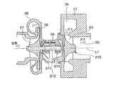
- FIG. 6 is Japanese Patent Laid-Open No. 2003-120303 (Patent Document 1) showing an example of a supercharger using such a radial turbine as a conventional technique.
- 01 is a turbine housing
- 04 is a spiral scroll portion formed in the turbine housing 01
- 05 is an exhaust gas exhaust passage formed in the inner periphery of the turbine housing 01
- 06 is a compressor housing
- 09 is a turbine housing 01.
- 010 is a turbine wheel, and a plurality of turbine blades 03 are fixed to the outer peripheral portion at equal intervals in the circumferential direction.
- Reference numeral 07 denotes a compressor impeller
- 08 denotes a diffuser provided at an air outlet of the compressor impeller 07
- 012 denotes a rotor shaft connecting the turbine wheel 010 and the compressor impeller 07.
- Reference numeral 011 denotes a pair of bearings that are attached to the bearing housing 09 and support the rotor shaft 012.
- L1 is the rotational axis of the turbine wheel 010, the compressor impeller, and the rotor shaft 012. *
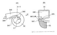
- FIG. 7A shows a schematic cross-sectional configuration diagram in the direction perpendicular to the axis L1 of the rotor shaft 012 in the vicinity of the tongue formed on the inner periphery of the exhaust gas inlet of the radial turbine of Patent Document 1, and FIG.
- the W arrow directional view of (A) is shown.
- 04 is a scroll portion
- 044 is an exhaust gas introduction port
- 045 is a flow passage 046 of a connection portion where exhaust gas from the exhaust gas introduction port 044 passes through the flow passage 046 and is introduced into the scroll portion 04.
- a tongue portion is formed to partition the blade side passage 047 flowing into the blade. Then, as shown in FIG.
- the tongue portion 045 receives exhaust gas heat from the flow path 046 side and the moving blade side passage 047 side, while the heat accumulated in the tongue portion 045 is represented by an arrow Z.
- the heat dissipation path is so narrow that the heat dissipation efficiency is not good. Accordingly, the temperature of the tongue 045 may be 800 to 900 ° C.
- the high-temperature exhaust gas from the engine passes through the flow path 046 and flows out to the moving blade side passage 047 while circling the scroll portion 04 along the spiral portion.
- the tongue portion 045 is exposed to the high temperature exhaust gas from both sides of the flow path 046 and the rotor blade side passage 047, and the heat radiation path of the tongue portion 045 is only in the Z direction [see FIG.
- the tongue portion 045 is likely to be fatigued due to surface oxidation or thermal stress.
- an expensive material for example, austenitic cast steel, ferritic cast steel, etc. having good oxidation resistance and fatigue resistance at high temperatures is used as the material of the turbine housing 01, which causes an increase in cost.
- the present invention was made to solve such problems, and by increasing the outside air exposed surface area outside the connecting portion (tongue portion) of the turbine housing and increasing the amount of heat released from the portion,
- the object is to reduce the cost by suppressing the heat accumulated in the tongue and lowering the heat-resistant grade of the material used for the portion.
- the present invention allows exhaust gas to flow in a radial direction from a spiral scroll portion formed in a turbine housing to a moving blade of the scroll portion so as to act on the moving blade.
- the flow path of the connection portion from the exhaust gas inlet to the turbine housing to the scroll portion is offset along the axis of the rotation axis of the turbine rotor, and the flow that flows into the flow path and the rotor blades by the offset.
- a wall surface exposed to the outside air is formed in the vicinity of the tongue portion that partitions the wing-side passage, and heat radiation near the tongue portion is performed by the wall surface.
- the axial length of the wall surface is changed in accordance with the offset amount, and the offset amount of the flow path is decreased toward the tip of the tongue portion.
- the flow loss of the exhaust gas can be suppressed by reducing the offset at the front end of the tongue and reducing the step at the entrance of the scroll part.
- the offset of the flow path is formed by deforming only the spiral inner peripheral side.
- the amount of deformation on the outer peripheral side of the scroll portion can be suppressed to prevent deterioration in the mountability to the engine, and the heat radiation of the tongue portion can be promoted.
- the offset is reduced from a portion of about 45 degrees toward the exhaust gas inflow side with the axis as a center, with reference to a line connecting the axis of the turbine scroll and the tip of the tongue. It is preferable that the offset is set to zero at the tip of the tongue.
- the range of the offset is decreased from a portion of approximately 45 degrees toward the exhaust gas inflow side with the axis at the center so that the offset becomes zero at the tip of the tongue, thereby allowing the exhaust gas flow.
- the direction in which the gas is guided is determined, and the flow loss of the exhaust gas can be suppressed.
- FIG. 3 is a cross-sectional view in the direction perpendicular to the turbine rotor axis of the tongue according to the first embodiment of the present invention.
- A) is a schematic structure figure of the exhaust gas distribution space part of the scroll part which concerns on 2nd Embodiment of this invention,
- B) is K section schematic sectional shape figure of (A),
- C) is M part of (A).
- a schematic cross-sectional shape figure and (D) show the N section schematic cross-sectional shape figure of (A).
- the image figure of the cross-sectional shape change of the exhaust gas distribution space part of the scroll part which concerns on 2nd Embodiment of this invention is shown.
- (A) is schematic structure figure of exhaust gas distribution space part of scroll part concerning 3rd Embodiment of this invention
- (B) is Q part schematic sectional shape figure of (A)
- C) is R part of (A).
- a schematic cross-sectional shape figure and (D) show the S section schematic cross-sectional shape figure of (A). Sectional drawing which follows the rotating shaft line of the supercharger using the radial turbine to which this invention is applied is shown.
- (A) is a cross-sectional view perpendicular to the turbine rotor axis of the tongue in the prior art
- (B) is a view taken in the direction of arrow W in (A).
- FIG. 6 showing the overall structure of a turbocharger using a radial turbine to which the present invention is applied, 01 is a turbine housing, 04 is a spiral scroll portion formed in the turbine housing 01, and 05 is a turbine housing 01.
- An exhaust gas exhaust passage formed in the inner periphery, 06 is a compressor housing, 09 is a turbine housing 01, and a bearing housing connecting the compressor housing 06.
- Reference numeral 010 denotes a turbine wheel, and a plurality of turbine blades 03 are fixed to the outer peripheral portion at equal intervals in the circumferential direction.
- Reference numeral 07 denotes a compressor impeller
- 08 denotes a diffuser provided at an air outlet of the compressor impeller 07
- 012 denotes a rotor shaft connecting the turbine wheel 010 and the compressor impeller 07.
- Reference numeral 011 denotes a pair of bearings attached to the bearing housing 09 and supporting the rotor shaft 12.
- L1 is a turbine wheel 010, a compressor impeller, and a rotor shaft 012 Is the axis of rotation.
- exhaust gas from an internal combustion engine enters the scroll 04 from the exhaust gas inlet, and rotates around the spiral of the scroll portion 04 and the outer periphery of the plurality of turbine rotor blades 03. It flows into the turbine rotor blade 03 from the side inlet end face, flows in the radial direction toward the center side of the turbine wheel 010, performs expansion work on the turbine wheel 010, flows in the axial direction, and is discharged from the exhaust gas outlet passage 05.
- the basic configuration of the turbocharger with a radial turbine is the same as that of the conventional technology.
- the shape of the scroll is improved.
- FIG. 1A is a cross-sectional view perpendicular to the turbine rotor axis of the tongue portion according to the first embodiment of the present invention
- FIG. 1B is a view of the scroll portion and the rotation axis of the turbine rotor as viewed from the arrow G in FIG.
- Reference numeral 3 denotes a flow path formed by the turbine housing 5 that allows the exhaust gas from the exhaust gas inlet to flow into the scroll portion 1.
- Reference numeral 1 denotes a scroll portion formed by a turbine housing 5 which is formed in a spiral shape and converts the exhaust gas flowing in from the flow path 3 into a spiral flow and ejects the exhaust gas toward the rotor blade 6 through the rotor blade side passage 4.
- Reference numeral 2 denotes a connecting portion between the flow path 3 and the scroll portion 1, which is a tongue portion that partitions the moving blade side passage 4.
- the flow path 3 has a structure that is deformed by an offset amount H along the axis L1 of the rotating shaft of the turbine rotor (rotor shaft in FIG. 6). As shown in FIG. 1B, the exhaust gas passage sectional area of the flow path 3 cannot be changed (changing the passage sectional area changes the performance of the turbocharger). Accordingly, the cross-sectional shape of the flow path 3 formed by the turbine housing 5 is maintained in a state that is offset from the broken line portion to the solid line portion along the axis L1, and accordingly, the tongue portion 2 is also offset.
- the outer wall portion of the turbine housing 5 where the tongue portion 2 is located is formed with a rotor blade side passage outer peripheral wall surface 21 exposed to the outside air, and a scroll side inner peripheral wall surface 22 is formed on the inner peripheral side of the scroll portion 1.
- the heat accumulated in the part 2 is easily dissipated. Therefore, the amount of heat accumulated in the tongue 2 is efficiently radiated from the entire turbine housing 5 in addition to the heat radiated from the rotor blade side passage outer peripheral wall surface 21 and the scroll side inner peripheral wall surface 22.
- FIG. 2 shows a cross section of the tongue 2 in a direction perpendicular to the axis L1 of the rotating shaft of the turbine rotor.
- the tongue 2 is inclined approximately 45 degrees toward the base end side (exhaust gas inlet side) of the tongue 2 around the axis L1 with reference to a reference line L2 connecting the axis L1 and the leading edge 23 of the tongue 2.
- a notch P1 having a length F from the tip edge 23 of the tongue 2 is provided up to a portion that intersects the line. Exhaust gas flows from the notch P ⁇ b> 1 to the rotor blade side passage 4. This is to reduce the amount of heat accumulated in the tongue 2 by reducing the portion of the tongue 2 exposed to the exhaust gas.
- the reason why the position of the notch length F of the tongue 2 is set to 45 degrees is that the thickness of the portion of the tongue 2 is approximately twice the thickness of the tip edge 23, and the heat to the entire turbine housing 5 is increased. The conduction increases and the heat dissipation efficiency of the tongue 2 is improved.
- the width of the notch may be determined arbitrarily. However, if the notch is made larger, the exhaust gas flowing from the flow path 3 to the rotor blade side passage 4 increases, and the performance of the turbocharger decreases. On the other hand, if it is too small, the amount of heat stored in the tongue 2 will increase and the temperature rise will increase. However, since the exposed surfaces 21 and 22 become large, the temperature rise is suppressed as compared with the conventional case. Therefore, the offset amount H may be determined so as to meet the specification status (required performance) of the turbocharger. As a result, the heat resistance grade of the material amount of the turbine housing 5 formed integrally with the tongue portion 2 can be lowered. As an example of the material, an expensive material such as austenitic cast steel or ferritic cast steel has been used conventionally, but it can be replaced with ferritic cast iron or the like.
- the heat radiation area of the outer wall portion of the turbine housing 5 where the tongue portion 2 is located is increased by offsetting the flow path 3 of the connecting portion along the axis L1, so that heat is radiated from the portion.
- the cost can be reduced by lowering the heat resistance grade of the material used for the turbine housing 5.
- the provision of the notch 23 has an effect of suppressing the amount of heat received by the tongue 2.
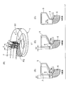
- FIG. 3 (A) is a schematic structural diagram of a space part through which the exhaust gas of the scroll part according to the second embodiment of the present invention flows, and (B), (C) and (D) are views of T in FIG. 3 (A).
- the schematic structure figure of the turbine housing 5 of the offset state in the tongue part 8 of each position of K, M, and N is shown.
- Reference numeral 7 denotes a flow path formed by the turbine housing 5 that allows the exhaust gas from the exhaust gas inlet to flow into the scroll portion 1.
- Reference numeral 8 denotes a connecting portion between the flow path 3 and the scroll portion 1, which is a tongue portion that partitions the moving blade side passage 4.
- the tongue portion 8 gives an offset amount E to the moving blade side passage 4 along the axis L1 of the rotating shaft of the turbine rotor (rotor shaft in FIG. 6).
- the offset amount E is decreased from the side toward the tip edge 81, and the tip edge 81 has an offset of 0 (zero).
- FIGS. 3B, 3 ⁇ / b> C, and 3 ⁇ / b> D the exhaust gas passage cross-sectional area of the flow passage 3 cannot be changed. (A change in passage cross-sectional area changes the performance of the turbocharger).
- the cross-sectional shape of the flow path 3 formed by the turbine housing 5 is maintained in a state where the offset amount E is set from the broken line portion to the solid line portion along the axis L1 while being maintained.
- the offset amount E1 and the M cross-section offset amount E2 a state of E1> E2 is formed, and the offset amount is zero in the N cross-section.
- the width of the notch P2 formed in the tongue 8 is smooth from the base end side position of the tongue 2 having the notch length F toward the tip edge 81 of the tongue 2 in FIG.
- the tip edge 81 is the same as the width of the rotor blade side passage 4.
- variety of the notch part P2 of FIG.3 (B), (C) and (D) is large in order of PK ⁇ PM ⁇ PN.
- FIG. 4 shows an image diagram of the cross-sectional shape change of the exhaust gas circulation space portion of the scroll portion according to the second embodiment.
- the K cross section represents FIG. 3 (B)
- the M cross section represents FIG. 3 (C)
- the N cross section represents FIG. 3 (D)
- the width GW represents a portion parallel to the axis L1. It corresponds to the side 51 of the outer peripheral portion.
- GH is the length of the axis L1 in the radial direction, and has a shape including the rotor blade side passage 4 from the outer peripheral portion of the scroll portion 1.
- the K cross-section offset amount E1 is also the largest, followed by the M cross-section offset amount E2, and the N cross-section has an offset amount of 0 (zero).
- the change state of the offset state in the tongue portion 8 is described at three positions.
- the change state of the offset amount E (E1, E2) may be changed smoothly or stepwise.
- the step at the entrance of the scroll part can be removed, so that the flow loss of the exhaust gas flowing inside is reduced, and the performance of the turbocharger can be maintained.
- the surface of the turbine housing 5 becomes wavy, the conduction heat dissipation area from the tongue 8 increases, and the temperature rise of the tongue 8 is suppressed.
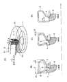
- FIG. 5 (A) is a schematic structural diagram of the space part through which the exhaust gas in the scroll part circulates, and (B), (C) and (D) are the positions of Q, R and S in the direction of the arrow U in FIG.
- the schematic structural drawing of the turbine housing 5 of the offset state in the tongue part 8 is shown.
- Reference numeral 9 denotes a flow path formed by the turbine housing 5 that allows the exhaust gas from the exhaust gas inlet to flow into the scroll portion 1.
- Reference numeral 8 denotes a connecting portion between the flow path 3 and the scroll portion 1, which is a tongue portion that partitions the moving blade side passage 4.
- the tongue portion 8 is offset from the moving blade side passage 4 by an offset amount J along the axis L1 of the rotating shaft of the turbine rotor (rotor shaft in FIG. 6).
- the offset amount J is reduced from the side toward the tip edge 81, and the tip edge 81 has a structure with an offset of zero.
- FIGS. 5B, 5C, and 5D in the present embodiment, the position of the outer peripheral portion 91 and the width V of the channel 9 are not changed, and the tongue portion is not changed. Only the portion 8 and the inner peripheral side wall of the scroll portion 1 are offset.
- the offset portion is changed from the general cross-sectional shape shown by the broken line to the shape of the solid line. It has changed. Accordingly, the cross-sectional area of the flow path 7 formed by the turbine housing 5 is maintained in the shape of the offset amount J (J1, J2) from the broken line portion to the solid line portion along the axis L1. Between the offset amount J1 of the Q cross section and the offset amount J2 of the R cross section, J1> J2 is formed, and the offset amount is 0 in the S cross section. The width of the notch P3 in FIGS.
- the width of the notch P2 formed in the tongue 8 is as shown in FIG. 3A from the base end side (exhaust gas inlet side) position of the tongue 2 having the notch length F to the tip of the tongue 2. It expands smoothly toward the edge 81, and the tip edge 81 has the same width as the rotor blade side passage 4.
- the operational effects of the present embodiment suppress the amount of deformation on the outer peripheral side of the scroll portion, prevent deterioration of mountability to the engine, and promote heat dissipation of the tongue portion. be able to.
- the turbine rotor In order to improve the output of the internal combustion engine, it is used in an internal combustion engine or the like, so that the turbine rotor is rotationally driven by flowing in a radial direction from a spiral scroll portion and then flowing in the rear axis direction after acting on the moving blade. It is good to use for the radial turbine comprised in this.
Abstract
Une structure de spirale de turbine d'une turbine radiale est caractérisée en ce que : un chemin d'écoulement (3) d'une section reliée à la spirale (1) est décalé (H) par rapport à une entrée de gaz d'échappement d'un carter de turbine (5) le long de l'axe (L1) d'un arbre rotatif d'un rotor de turbine ; et une encoche (P), par laquelle le gaz d'échappement s'écoule depuis le chemin d'écoulement (3) jusqu'à un passage latéral (4) de pale de rotor, est disposée sur une languette (2) qui sépare le chemin d'écoulement (3) et le passage latéral (4) de pale de rotor qui débouche dans la pale de rotor (6).
Priority Applications (3)
| Application Number | Priority Date | Filing Date | Title |
|---|---|---|---|
| US13/879,426 US9328738B2 (en) | 2010-12-27 | 2011-12-16 | Turbine scroll part structure |
| EP11853195.3A EP2617961B1 (fr) | 2010-12-27 | 2011-12-16 | Turbine radiale |
| CN201180052624.2A CN103261622B (zh) | 2010-12-27 | 2011-12-16 | 涡轮的涡旋部结构 |
Applications Claiming Priority (2)
| Application Number | Priority Date | Filing Date | Title |
|---|---|---|---|
| JP2010-291359 | 2010-12-27 | ||
| JP2010291359A JP5433560B2 (ja) | 2010-12-27 | 2010-12-27 | タービンスクロール部構造 |
Publications (1)
| Publication Number | Publication Date |
|---|---|
| WO2012090724A1 true WO2012090724A1 (fr) | 2012-07-05 |
Family
ID=46382837
Family Applications (1)
| Application Number | Title | Priority Date | Filing Date |
|---|---|---|---|
| PCT/JP2011/079154 WO2012090724A1 (fr) | 2010-12-27 | 2011-12-16 | Structure de spirale de turbine |
Country Status (5)
| Country | Link |
|---|---|
| US (1) | US9328738B2 (fr) |
| EP (1) | EP2617961B1 (fr) |
| JP (1) | JP5433560B2 (fr) |
| CN (1) | CN103261622B (fr) |
| WO (1) | WO2012090724A1 (fr) |
Families Citing this family (15)
| Publication number | Priority date | Publication date | Assignee | Title |
|---|---|---|---|---|
| EP2940270B1 (fr) | 2012-12-27 | 2017-04-26 | Mitsubishi Heavy Industries, Ltd. | Turbocompresseur à géométrie variable |
| JP6112223B2 (ja) * | 2013-11-22 | 2017-04-12 | 株式会社Ihi | 遠心圧縮機及び過給機 |
| JP5870083B2 (ja) | 2013-12-27 | 2016-02-24 | 三菱重工業株式会社 | タービン |
| US10400617B2 (en) | 2014-02-28 | 2019-09-03 | Mitsubishi Heavy Industries Engine & Turbocharger, Ltd. | Sheet-metal turbine housing |
| CN105221334B (zh) * | 2014-06-12 | 2016-12-14 | 山西华旗风能科技有限公司 | 一种集风装置 |
| JP6351049B2 (ja) * | 2014-11-04 | 2018-07-04 | 三菱重工エンジン&ターボチャージャ株式会社 | タービンハウジングおよびタービンハウジングの製造方法 |
| DE102015014900A1 (de) | 2015-10-22 | 2017-04-27 | GM Global Technology Operations LLC (n. d. Ges. d. Staates Delaware) | Radialturbinengehäuse |
| EP3409920B1 (fr) | 2016-03-30 | 2021-06-16 | Mitsubishi Heavy Industries Engine & Turbocharger, Ltd. | Turbocompresseur |
| CN109563770B (zh) * | 2016-12-28 | 2021-05-18 | 三菱重工发动机和增压器株式会社 | 涡轮机及涡轮增压器 |
| JP6947304B2 (ja) * | 2018-06-29 | 2021-10-13 | 株式会社Ihi | タービンおよび過給機 |
| DE112019006695T5 (de) * | 2019-02-25 | 2021-10-07 | Mitsubishi Heavy Industries Engine & Turbocharger, Ltd. | Turbinengehäuse und Turbolader |
| DE202021106090U1 (de) * | 2021-11-08 | 2023-02-09 | BorgWarner Inc. | Turbinengehäuse für einen Abgasturbolader |
| US11851202B1 (en) | 2022-06-23 | 2023-12-26 | Pratt & Whitney Canada Corp. | Aircraft engine, gas turbine intake therefore, and method of guiding exhaust gasses |
| US11891947B2 (en) | 2022-06-23 | 2024-02-06 | Pratt & Whitney Canada Corp. | Aircraft engine, gas turbine intake therefore, and method of guiding exhaust gasses |
| US11821361B1 (en) | 2022-07-06 | 2023-11-21 | Pratt & Whitney Canada Corp. | Gas turbine intake for aircraft engine and method of inspection thereof |
Citations (3)
| Publication number | Priority date | Publication date | Assignee | Title |
|---|---|---|---|---|
| JPH10231706A (ja) * | 1997-02-19 | 1998-09-02 | Mitsubishi Heavy Ind Ltd | タービンスクロール |
| JP2003120303A (ja) | 2001-10-19 | 2003-04-23 | Mitsubishi Heavy Ind Ltd | ラジアルタービンのスクロール構造 |
| JP2006161574A (ja) * | 2004-12-02 | 2006-06-22 | Toyota Motor Corp | ターボチャージャのタービンハウジング |
Family Cites Families (10)
| Publication number | Priority date | Publication date | Assignee | Title |
|---|---|---|---|---|
| US4530640A (en) * | 1982-09-29 | 1985-07-23 | Roto-Master, Inc. | Method and apparatus for wastegating turbocharged engine with divided exhaust system |
| JP3253978B2 (ja) | 1990-12-10 | 2002-02-04 | 雅弘 井上 | タービンスクロール |
| JP3586515B2 (ja) * | 1996-06-20 | 2004-11-10 | 三菱重工業株式会社 | タービンスクロール |
| FR2801072B1 (fr) * | 1999-11-17 | 2002-11-08 | Renault | Turbocompresseur comportant des entrees de turbine alignees selon un plan radial |
| US6478553B1 (en) | 2001-04-24 | 2002-11-12 | General Motors Corporation | High thrust turbocharger rotor with ball bearings |
| US6742989B2 (en) | 2001-10-19 | 2004-06-01 | Mitsubishi Heavy Industries, Ltd. | Structures of turbine scroll and blades |
| DE50312707D1 (de) * | 2003-03-19 | 2010-06-24 | Abb Turbo Systems Ag | Abgasturbinengehäuse |
| JPWO2005010330A1 (ja) * | 2003-07-29 | 2006-09-07 | 日野自動車株式会社 | ターボチャージャ |
| DE102007055507A1 (de) * | 2007-11-21 | 2009-06-04 | Georg Emanuel Koppenwallner | Schräglippenspirale |
| US8266906B2 (en) * | 2009-03-11 | 2012-09-18 | GM Global Technology Operations LLC | Asymmetric split-inlet turbine housing |
-
2010
- 2010-12-27 JP JP2010291359A patent/JP5433560B2/ja not_active Expired - Fee Related
-
2011
- 2011-12-16 WO PCT/JP2011/079154 patent/WO2012090724A1/fr active Application Filing
- 2011-12-16 EP EP11853195.3A patent/EP2617961B1/fr not_active Not-in-force
- 2011-12-16 US US13/879,426 patent/US9328738B2/en active Active
- 2011-12-16 CN CN201180052624.2A patent/CN103261622B/zh not_active Expired - Fee Related
Patent Citations (3)
| Publication number | Priority date | Publication date | Assignee | Title |
|---|---|---|---|---|
| JPH10231706A (ja) * | 1997-02-19 | 1998-09-02 | Mitsubishi Heavy Ind Ltd | タービンスクロール |
| JP2003120303A (ja) | 2001-10-19 | 2003-04-23 | Mitsubishi Heavy Ind Ltd | ラジアルタービンのスクロール構造 |
| JP2006161574A (ja) * | 2004-12-02 | 2006-06-22 | Toyota Motor Corp | ターボチャージャのタービンハウジング |
Also Published As
| Publication number | Publication date |
|---|---|
| EP2617961A4 (fr) | 2018-01-03 |
| US9328738B2 (en) | 2016-05-03 |
| EP2617961A1 (fr) | 2013-07-24 |
| CN103261622A (zh) | 2013-08-21 |
| JP2012137068A (ja) | 2012-07-19 |
| EP2617961B1 (fr) | 2019-05-01 |
| JP5433560B2 (ja) | 2014-03-05 |
| US20130266433A1 (en) | 2013-10-10 |
| CN103261622B (zh) | 2015-11-25 |
Similar Documents
| Publication | Publication Date | Title |
|---|---|---|
| JP5433560B2 (ja) | タービンスクロール部構造 | |
| JP5047364B2 (ja) | ラジアルタービンのスクロール構造 | |
| JP5665486B2 (ja) | ツインスクロール型ターボチャージャのタービンハウジング | |
| US20140205441A1 (en) | Seal assembly including grooves in a radially outwardly facing side of a platform in a gas turbine engine | |
| US9068513B2 (en) | Seal assembly including grooves in an inner shroud in a gas turbine engine | |
| US20150139805A1 (en) | Rotary machine | |
| JP5088610B2 (ja) | 遠心圧縮機ケーシング | |
| JP2009281323A (ja) | 圧縮機のハウジング | |
| WO2014087966A1 (fr) | Compresseur centrifuge, surpresseur muni de celui-ci, et procédé de fonctionnement du compresseur centrifuge | |
| JP5975057B2 (ja) | タービンハウジング | |
| US9816395B2 (en) | Turbine housing | |
| JP2003227344A (ja) | ターボチャージャ | |
| US9638058B2 (en) | Scroll portion structure for radial turbine or diagonal flow turbine | |
| JP6621982B2 (ja) | コンプレッサ、これを備えた過給機、ならびにコンプレッサのスロート通路幅調整方法 | |
| EP3470648B1 (fr) | Turbocompresseur | |
| JP5797724B2 (ja) | 排気ガスターボチャージャ | |
| CN110344927B (zh) | 内燃机 | |
| JPWO2019087279A1 (ja) | タービン及びこれを備えたターボチャージャ | |
| JP2008196327A (ja) | ターボ過給機 | |
| JP7336026B2 (ja) | タービン及びこのタービンを備えるターボチャージャ | |
| JP2016173068A (ja) | 排気ターボ過給機 | |
| JP4736817B2 (ja) | ターボチャージャ | |
| JP2008045425A (ja) | 遠心圧縮機 | |
| JP2011169233A (ja) | タービンの可変ノズル構造 |
Legal Events
| Date | Code | Title | Description |
|---|---|---|---|
| 121 | Ep: the epo has been informed by wipo that ep was designated in this application |
Ref document number: 11853195 Country of ref document: EP Kind code of ref document: A1 |
|
| WWE | Wipo information: entry into national phase |
Ref document number: 2011853195 Country of ref document: EP |
|
| WWE | Wipo information: entry into national phase |
Ref document number: 13879426 Country of ref document: US |
|
| NENP | Non-entry into the national phase |
Ref country code: DE |