WO2012086427A1 - 集電体を備える蓄電素子及びこの蓄電素子を備える車両 - Google Patents
集電体を備える蓄電素子及びこの蓄電素子を備える車両 Download PDFInfo
- Publication number
- WO2012086427A1 WO2012086427A1 PCT/JP2011/078456 JP2011078456W WO2012086427A1 WO 2012086427 A1 WO2012086427 A1 WO 2012086427A1 JP 2011078456 W JP2011078456 W JP 2011078456W WO 2012086427 A1 WO2012086427 A1 WO 2012086427A1
- Authority
- WO
- WIPO (PCT)
- Prior art keywords
- electrode
- case
- current collector
- attachment portion
- tip
- Prior art date
- Legal status (The legal status is an assumption and is not a legal conclusion. Google has not performed a legal analysis and makes no representation as to the accuracy of the status listed.)
- Ceased
Links
Images



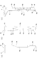


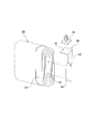
Classifications
-
- H—ELECTRICITY
- H01—ELECTRIC ELEMENTS
- H01M—PROCESSES OR MEANS, e.g. BATTERIES, FOR THE DIRECT CONVERSION OF CHEMICAL ENERGY INTO ELECTRICAL ENERGY
- H01M50/00—Constructional details or processes of manufacture of the non-active parts of electrochemical cells other than fuel cells, e.g. hybrid cells
- H01M50/50—Current conducting connections for cells or batteries
- H01M50/528—Fixed electrical connections, i.e. not intended for disconnection
-
- H—ELECTRICITY
- H01—ELECTRIC ELEMENTS
- H01G—CAPACITORS; CAPACITORS, RECTIFIERS, DETECTORS, SWITCHING DEVICES, LIGHT-SENSITIVE OR TEMPERATURE-SENSITIVE DEVICES OF THE ELECTROLYTIC TYPE
- H01G11/00—Hybrid capacitors, i.e. capacitors having different positive and negative electrodes; Electric double-layer [EDL] capacitors; Processes for the manufacture thereof or of parts thereof
- H01G11/66—Current collectors
- H01G11/70—Current collectors characterised by their structure
-
- H—ELECTRICITY
- H01—ELECTRIC ELEMENTS
- H01G—CAPACITORS; CAPACITORS, RECTIFIERS, DETECTORS, SWITCHING DEVICES, LIGHT-SENSITIVE OR TEMPERATURE-SENSITIVE DEVICES OF THE ELECTROLYTIC TYPE
- H01G11/00—Hybrid capacitors, i.e. capacitors having different positive and negative electrodes; Electric double-layer [EDL] capacitors; Processes for the manufacture thereof or of parts thereof
- H01G11/78—Cases; Housings; Encapsulations; Mountings
- H01G11/82—Fixing or assembling a capacitive element in a housing, e.g. mounting electrodes, current collectors or terminals in containers or encapsulations
-
- H—ELECTRICITY
- H01—ELECTRIC ELEMENTS
- H01M—PROCESSES OR MEANS, e.g. BATTERIES, FOR THE DIRECT CONVERSION OF CHEMICAL ENERGY INTO ELECTRICAL ENERGY
- H01M10/00—Secondary cells; Manufacture thereof
- H01M10/04—Construction or manufacture in general
- H01M10/0413—Large-sized flat cells or batteries for motive or stationary systems with plate-like electrodes
-
- H—ELECTRICITY
- H01—ELECTRIC ELEMENTS
- H01M—PROCESSES OR MEANS, e.g. BATTERIES, FOR THE DIRECT CONVERSION OF CHEMICAL ENERGY INTO ELECTRICAL ENERGY
- H01M10/00—Secondary cells; Manufacture thereof
- H01M10/04—Construction or manufacture in general
- H01M10/0431—Cells with wound or folded electrodes
-
- H—ELECTRICITY
- H01—ELECTRIC ELEMENTS
- H01M—PROCESSES OR MEANS, e.g. BATTERIES, FOR THE DIRECT CONVERSION OF CHEMICAL ENERGY INTO ELECTRICAL ENERGY
- H01M4/00—Electrodes
- H01M4/02—Electrodes composed of, or comprising, active material
- H01M4/64—Carriers or collectors
- H01M4/70—Carriers or collectors characterised by shape or form
-
- H—ELECTRICITY
- H01—ELECTRIC ELEMENTS
- H01M—PROCESSES OR MEANS, e.g. BATTERIES, FOR THE DIRECT CONVERSION OF CHEMICAL ENERGY INTO ELECTRICAL ENERGY
- H01M50/00—Constructional details or processes of manufacture of the non-active parts of electrochemical cells other than fuel cells, e.g. hybrid cells
- H01M50/50—Current conducting connections for cells or batteries
- H01M50/531—Electrode connections inside a battery casing
- H01M50/533—Electrode connections inside a battery casing characterised by the shape of the leads or tabs
-
- H—ELECTRICITY
- H01—ELECTRIC ELEMENTS
- H01M—PROCESSES OR MEANS, e.g. BATTERIES, FOR THE DIRECT CONVERSION OF CHEMICAL ENERGY INTO ELECTRICAL ENERGY
- H01M50/00—Constructional details or processes of manufacture of the non-active parts of electrochemical cells other than fuel cells, e.g. hybrid cells
- H01M50/50—Current conducting connections for cells or batteries
- H01M50/531—Electrode connections inside a battery casing
- H01M50/538—Connection of several leads or tabs of wound or folded electrode stacks
-
- H—ELECTRICITY
- H01—ELECTRIC ELEMENTS
- H01M—PROCESSES OR MEANS, e.g. BATTERIES, FOR THE DIRECT CONVERSION OF CHEMICAL ENERGY INTO ELECTRICAL ENERGY
- H01M2220/00—Batteries for particular applications
- H01M2220/20—Batteries in motive systems, e.g. vehicle, ship, plane
-
- Y—GENERAL TAGGING OF NEW TECHNOLOGICAL DEVELOPMENTS; GENERAL TAGGING OF CROSS-SECTIONAL TECHNOLOGIES SPANNING OVER SEVERAL SECTIONS OF THE IPC; TECHNICAL SUBJECTS COVERED BY FORMER USPC CROSS-REFERENCE ART COLLECTIONS [XRACs] AND DIGESTS
- Y02—TECHNOLOGIES OR APPLICATIONS FOR MITIGATION OR ADAPTATION AGAINST CLIMATE CHANGE
- Y02E—REDUCTION OF GREENHOUSE GAS [GHG] EMISSIONS, RELATED TO ENERGY GENERATION, TRANSMISSION OR DISTRIBUTION
- Y02E60/00—Enabling technologies; Technologies with a potential or indirect contribution to GHG emissions mitigation
- Y02E60/10—Energy storage using batteries
-
- Y—GENERAL TAGGING OF NEW TECHNOLOGICAL DEVELOPMENTS; GENERAL TAGGING OF CROSS-SECTIONAL TECHNOLOGIES SPANNING OVER SEVERAL SECTIONS OF THE IPC; TECHNICAL SUBJECTS COVERED BY FORMER USPC CROSS-REFERENCE ART COLLECTIONS [XRACs] AND DIGESTS
- Y02—TECHNOLOGIES OR APPLICATIONS FOR MITIGATION OR ADAPTATION AGAINST CLIMATE CHANGE
- Y02E—REDUCTION OF GREENHOUSE GAS [GHG] EMISSIONS, RELATED TO ENERGY GENERATION, TRANSMISSION OR DISTRIBUTION
- Y02E60/00—Enabling technologies; Technologies with a potential or indirect contribution to GHG emissions mitigation
- Y02E60/13—Energy storage using capacitors
-
- Y—GENERAL TAGGING OF NEW TECHNOLOGICAL DEVELOPMENTS; GENERAL TAGGING OF CROSS-SECTIONAL TECHNOLOGIES SPANNING OVER SEVERAL SECTIONS OF THE IPC; TECHNICAL SUBJECTS COVERED BY FORMER USPC CROSS-REFERENCE ART COLLECTIONS [XRACs] AND DIGESTS
- Y02—TECHNOLOGIES OR APPLICATIONS FOR MITIGATION OR ADAPTATION AGAINST CLIMATE CHANGE
- Y02P—CLIMATE CHANGE MITIGATION TECHNOLOGIES IN THE PRODUCTION OR PROCESSING OF GOODS
- Y02P70/00—Climate change mitigation technologies in the production process for final industrial or consumer products
- Y02P70/50—Manufacturing or production processes characterised by the final manufactured product
-
- Y—GENERAL TAGGING OF NEW TECHNOLOGICAL DEVELOPMENTS; GENERAL TAGGING OF CROSS-SECTIONAL TECHNOLOGIES SPANNING OVER SEVERAL SECTIONS OF THE IPC; TECHNICAL SUBJECTS COVERED BY FORMER USPC CROSS-REFERENCE ART COLLECTIONS [XRACs] AND DIGESTS
- Y02—TECHNOLOGIES OR APPLICATIONS FOR MITIGATION OR ADAPTATION AGAINST CLIMATE CHANGE
- Y02T—CLIMATE CHANGE MITIGATION TECHNOLOGIES RELATED TO TRANSPORTATION
- Y02T10/00—Road transport of goods or passengers
- Y02T10/60—Other road transportation technologies with climate change mitigation effect
- Y02T10/70—Energy storage systems for electromobility, e.g. batteries
Definitions
- the present invention relates to a power storage element including a current collector. Moreover, this invention relates to a vehicle provided with this electrical storage element.
- Patent Document 1 describes an invention relating to a prismatic secondary battery in which a power generation element and a current collector are connected without increasing the internal resistance of the battery.
- a power generation element (“winding electrode body” in Patent Document 1) 120 is placed inside a battery case (“Battery Can” in Patent Document 1) 110.
- the positive electrode terminal 131 and the negative electrode terminal 131 protrude from the inside of the battery case 110 to the outside, and the power generation element 120 and each of the electrode terminals 131 and 132 are connected to the current collector ( In Patent Document 1, they are connected by “current collecting member”) 140.
- the power generation element 120 is obtained by interposing a strip-shaped separator between a strip-shaped positive electrode plate and a negative electrode plate (none of which are individually shown), and winding them in a spiral shape and compressing them flatly.
- the power generation element 120 has a central hole 121 as shown in FIG. 12 (only one of them is shown in FIG. 12) at the winding center of both ends.
- the power generation element 120 has the core body bundle part 122 from which the edge part of the positive electrode core body and the negative electrode core body protruded on the both sides, respectively.
- the power generation element 120 is housed in the battery case 110 such that each central hole 121 faces the end surface of the battery case 110 and the core bundle portions 122 are positioned at both ends of the battery case 110.
- the current collector 140 includes a terminal connection portion 141 that is welded to the electrode terminals 131 and 132, a core body connection portion 142 that is inserted into the central hole 121 of the power generation element 120, a terminal connection portion 141, and a core body connection portion 142.
- the connection part 143 which connects is provided.
- the current collector 140 is formed by pressing a single rectangular metal plate.
- the connecting portion 143 has a width that is slightly narrower than the width of the power generation element 120 in the compression direction.
- the connecting portion 143 is bent in a direction perpendicular to the core connecting portion 142 (L-shaped in front view).
- the core body connecting portion 142 is folded in half with the center line in the length direction of the core body connecting portion 142 as a fold, and the fold projects in the bending direction of the terminal connecting portion 141.
- the core body connection part 142 is inserted into the central hole 121 of the power generation element 120 and the core body bundle part 122 of the power generation element 120 is pressurized, so that the core body connection part 142 and the power generation element 120 are pressure-bonded. In this state, by performing ultrasonic welding from one outer peripheral side surface of the core body bundle portion 122, the core body connection portion 142 and the inner peripheral surface of the core body bundle portion 122 are connected without increasing the internal resistance. .
- the battery case 110 is a combination of a bottomed rectangular tube-shaped case main body 111 having an opening and a lid body 112 that closes the opening of the case main body 111.
- the edge of the opening of case body 111 and the outer periphery of lid 112 are welded.
- the lid body 112 is provided with a hole (not numbered) through which the electrode terminals 131 and 132 pass.
- the electrode terminals 131 and 132 protrude from the hole of the lid body 112 and are fixed to the lid body 112 by rivets.
- the electric power generated by the power generation element 120 is taken out from the electrode terminals 131 and 132 protruding from the lid body 112.
- the power generation element 120 is suspended from the lid 112 by the current collector 140. Further, the terminal connection portion 141 of the current collector 140 is fixed to the lid 112 of the battery case 110.
- the power generation element 120 vibrates with a different amplitude and frequency from the case body 111. Then, stress is generated in a portion of the current collector 140 connected to the power generation element 120 or a bent portion (linking portion 143), and eventually these portions are broken, and the battery may not function. is there.
- the current collector 140 described in Patent Document 1 is based on a vibration test profile according to the United Nations Transport Standards Test (UN Transport Test). , 12, 15, 18, 20, and 22G, and repeated tests were conducted. As a result, some fractures occurred at 16G and 8G.
- UN Transport Test United Nations Transport Standards Test
- the current collector 140 is not only welded to the power generating element 120 and the electrode terminals 131 and 132 but also the case body 111 and the lid 112 of the battery case 110 are welded. Even if the current collector 140 is broken, the current collector 140 cannot be taken out and replaced.
- an object of the present invention is to provide a power storage element in which a current collector is not easily broken even when vibration is applied, and a vehicle including the power storage element.
- the electricity storage device is: A case having a first inner surface and a second inner surface adjacent to the first inner surface; An electrode body housed in the case, the electrode body including a positive electrode plate and a negative electrode plate insulated from each other; An electrode terminal disposed outside the case; A current collector that is housed in the case and electrically connects the electrode body and the electrode terminal; A tip edge of a tip portion of the current collector is supported by the first inner surface of the case.
- the tip portion of the current collector can be bent so as to be in contact with the second inner surface of the case.
- the tip of the current collector can be bent along the first inner surface of the case.
- the tip edge of the tip portion of the current collector is supported by the first inner surface of the case by contacting the first inner surface of the case. Can be.
- a gap is provided between the tip edge of the tip of the current collector and the first inner surface of the case;
- the current collector includes a spacer at the interval, The tip edge of the tip portion of the current collector can be supported by the first inner surface of the case via the spacer.
- the spacer preferably has an insulating property.
- the current collector is an electrode attachment portion disposed between an end portion of the electrode body and the second inner surface of the case, and is an electrode electrically connected to the end portion of the electrode body With an attachment section, The tip edge of the tip of the electrode attachment portion can be supported by the first inner surface of the case.
- the current collector is An internal connection connected to the electrode terminal; An electrode attachment portion disposed between an end portion of the electrode body and the second inner surface of the case, wherein the electrode attachment portion is electrically connected to the end portion of the electrode body; An intermediate portion interposed between the internal connection portion and the electrode attachment portion, The intermediate portion can have a spring property.
- the electrode attachment portion is provided with an opening along the length direction of the electrode attachment portion,
- the electrode attachment portion may include a protrusion connected to the end portion of the electrode body at an edge of the opening.
- the strength on the base end side of the electrode attachment portion is higher than the strength on the tip end side of the electrode attachment portion.
- the electrode attachment portion includes a notch at each of an end portion of the opening portion on the base end portion side of the electrode attachment portion and an end portion of the opening portion on the distal end side of the electrode attachment portion,
- the opening angle of the notch on the base end side of the electrode attachment portion may be smaller than the opening angle of the notch on the distal end side of the electrode attachment portion.
- the notch is provided with a retaining hole at the tip of the notch,
- the retaining hole of the notch on the base end side of the electrode attaching portion can be made smaller than the retaining hole of the notch on the distal end side of the electrode attaching portion.
- the width of the electrode attachment portion on the proximal end side can be wider than the width of the electrode attachment portion on the distal end side.
- a vehicle according to the present invention includes any one of the above storage elements.
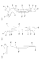
- (a) is a front view
- (b) is a side view
- (c) is a perspective view. It is a partially broken enlarged front view of the battery. It is a collector which concerns on other embodiment, Comprising: (a), (b) is a front view of an example from which each differs. It is a partially broken front view of the conventional battery. It is a principal part disassembled perspective view of the battery.
- the battery according to this embodiment is A battery case having a first inner surface and a second inner surface adjacent to the first inner surface; A power generation element housed in the battery case, the power generation element including a positive electrode plate and a negative electrode plate insulated from each other; An electrode terminal arranged outside the battery case; It is housed inside the battery case, and includes a current collector that electrically connects the power generation element and the electrode terminal, The tip edge of the tip of the current collector is supported by the first inner surface of the battery case.
- the tip edge of the tip part (the end of the current collector fixed to the battery case in a state of being electrically insulated from the battery case is the end opposite to the fixed end) Is supported on the first inner surface of the battery case (in an electrically insulated state), the power generation element is not suspended from the current collector, and the power generation element, the current collector, and the battery case are not It becomes an integrated state. Therefore, even if vibration is applied to the battery, the power generation element, the current collector, and the battery case vibrate integrally. That is, the power generation element does not vibrate with an amplitude or frequency different from that of the battery case. For this reason, stress is not generated in a portion of the current collector that is connected to the power generation element, and the current collector can be prevented from breaking.
- the tip of the current collector can be bent so as to be in contact with the second inner surface of the battery case.
- the tip of the current collector is bent so that the tip of the current collector contacts the second inner surface of the battery case, so that the tip of the current collector becomes like a stay. For this reason, the power generation element can be supported in a stable state.
- the tip of the current collector can be bent along the first inner surface of the battery case.
- the front end portion of the current collector is bent along the first inner surface of the battery case, so that the front end portion of the current collector is in contact with the first inner surface of the battery case. For this reason, the power generation element can be supported in a stable state.
- the tip edge of the tip portion of the current collector is supported by the first inner surface of the battery case by contacting the first inner surface of the battery case. it can.
- the tip edge of the tip of the current collector is in contact with the first inner surface of the battery case, so that the tip edge of the tip of the current collector is supported by the first inner surface of the battery case. .
- the power generation element, the current collector, and the battery case can be integrated.
- tip part of an electrical power collector here and the 1st inner surface of a battery case contact includes the state where the insulator interposes between both.
- a gap is provided between the leading edge of the tip of the current collector and the first inner surface of the battery case;
- the current collector includes a spacer in the interval, The tip edge of the tip of the current collector can be supported on the first inner surface of the battery case via the spacer.
- the tip edge of the tip of the current collector is supported on the first inner surface of the battery case via the spacer. For this reason, the power generation element, the current collector, and the battery case can be integrated.
- the spacer preferably has an insulating property.
- the insulating spacer is interposed between the leading edge of the tip of the current collector and the first inner surface of the battery case, the insulation between the current collector and the battery case is achieved. Can be secured.
- the tip edge of the current collector When the tip of the current collector is bent so as to be along the first inner surface of the battery case, the tip edge of the current collector has an insulating spacer between the first inner surface of the battery case. There is no piercing between them. For this reason, it is possible to prevent the insulating spacer from being damaged. Note that even if the tip of the current collector is bent in an arc shape, the bent portion does not pierce the insulating spacer, and similarly, the insulating spacer is not damaged. can do.
- the current collector is an electrode attachment portion disposed between the end portion of the power generation element and the second inner surface of the battery case, and includes an electrode attachment portion electrically connected to the end portion of the power generation element , The tip edge of the tip of the electrode attachment portion can be supported by the first inner surface of the battery case.
- the tip edge of the tip of the electrode attachment portion is supported by the first inner surface of the battery case, so that the power generation element is not suspended from the current collector, and the power generation element and the current collector are not suspended.
- the body and the battery case are integrated. Therefore, even if vibration is applied to the battery, the power generation element, the current collector, and the battery case vibrate integrally. That is, the power generation element does not vibrate with an amplitude or frequency different from that of the battery case. For this reason, stress is not generated in a portion of the electrode attachment portion connected to the power generation element, and the current collector can be prevented from breaking.
- Current collector An internal connection connected to the electrode terminal; An electrode attachment portion disposed between the end portion of the power generation element and the second inner surface of the battery case, the electrode attachment portion electrically connected to the end portion of the power generation element; An intermediate portion interposed between the internal connection portion and the electrode attachment portion, The intermediate portion can have a spring property.
- the electrode attachment portion is provided with an opening along the length direction of the electrode attachment portion,
- the electrode attachment portion may be provided with a protrusion connected to the end of the power generation element at the edge of the opening.
- the protrusion provided on the edge of the opening is connected to the power generation element. And it can make it easy to connect the positive electrode plate or negative electrode plate of an electric power generation element, and an electrode attachment part by being a protrusion.
- the strength on the base end side of the electrode attachment portion is preferably higher than the strength on the tip end side of the electrode attachment portion.
- the strength on the base end side of the electrode attachment portion is higher than the strength on the tip end side of the electrode attachment portion, thereby suppressing breakage on the base end side of the electrode attachment portion. can do.
- the electrode attachment portion includes a notch at each of an end portion of the opening portion on the proximal end side of the electrode attachment portion and an end portion of the opening portion on the distal end side of the electrode attachment portion
- the opening angle of the notch on the proximal end side of the electrode attachment portion can be made smaller than the opening angle of the notch on the distal end side of the electrode attachment portion.
- the end of the opening on the proximal end side of the electrode attachment portion and the end of the opening on the distal end side of the electrode attachment portion are notched, and the proximal end portion of the electrode attachment portion Since the opening angle of the notch on the side is smaller than the opening angle of the notch on the tip side of the electrode attachment portion, the strength on the base end side of the electrode attachment portion is increased. It can be higher than the strength at the side.
- the notch has a retaining hole at the tip of the notch,
- the notch retaining hole on the base end side of the electrode attachment portion can be made smaller than the notching hole on the distal end side of the electrode attachment portion.
- the notch is provided at the tip of the notch, and the notch on the base end side of the electrode attachment portion is more than the notch on the tip side of the electrode attachment portion.
- the strength around the notch retaining hole on the base end side of the electrode attaching portion can be made higher than the strength around the notch retaining hole on the distal end side of the electrode attaching portion. it can.
- the width of the electrode attachment portion on the base end side can be wider than the width of the electrode attachment portion on the tip end side.
- the width on the base end side of the electrode attachment portion is wider than the width on the tip end side of the electrode attachment portion, the strength on the base end portion side of the electrode attachment portion can be increased. It is possible to make it higher than the strength on the tip side of the attachment portion.
- the vehicle according to the present embodiment includes any one of the batteries described above.
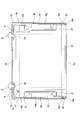
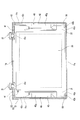
- the battery according to the first embodiment includes a metal battery case 10, a power generation element 20 housed in the battery case 10, a positive electrode terminal 31 and a negative electrode protruding outward from the battery case 10, as in the conventional case. Electrode terminal 32, current collector 40 for connecting power generating element 20 and electrode terminals 31 and 32, and the like.
- the battery case 10 is a combination of a bottomed rectangular tube-shaped case body 11 having an opening and a lid 12 that closes the opening of the case body 11. After assembling both 11 and 12, the edge of the opening part of case body 11 and the outer periphery of lid 12 are welded, and both 11 and 12 are united.
- the case main body 11 has a pair of opposing side plate portions 11b and a pair of opposing end plate portions 11c erected on the periphery of the rectangular bottom portion 11a.
- the case main body 11 is formed in a thin bottomed rectangular tube shape with a small depth by making the pair of end plate portions 11c narrower (than the pair of side plate portions 11b).
- Such a thin case body 11 can provide better heat dissipation than a non-thin case body.
- the inner surface of the bottom 11a of the case body 11 corresponds to the first inner surface of the present invention
- the inner surfaces of the side plate portion 11b and the end plate portion 11c of the case body 11 correspond to the second inner surface of the present invention. To do.
- the lid 12 is formed with holes (not numbered) through which the electrode terminals 31 and 32 pass.
- the electrode terminals 31 and 32 penetrate the hole of the lid body 12 and are fixed to the lid body 12 like rivets. Therefore, the outer ends of the electrode terminals 31 and 32 protrude from the lid body 12, and the inner ends of the electrode terminals 31 and 32 protrude into the battery case 10.
- the power generation element 20 is obtained by interposing a strip-shaped separator 23 between a strip-shaped positive plate 21 and a strip-shaped negative plate 22 and winding them flat. Further, on one end side of the power generation element 20, the positive electrode plate 21 protrudes from the separator 23 and is exposed, and on the other end side of the power generation element 20, the negative electrode plate 22 protrudes from the separator 23 and is exposed.
- the power generating element 20 has an axis parallel to the bottom portion 11a of the battery case 10, that is, the exposed end portions of the positive electrode plate 21 and the negative electrode plate 22 face each end plate portion 11c of the battery case 10. In this way, the battery case 10 is accommodated.
- the current collector 40 includes a positive current collector 40 that connects the power generation element 20 (the positive electrode plate 21 exposed from one end portion thereof, that is, the end portion of the positive electrode plate 21) and the positive electrode terminal 31, and the power generation element 20. (Negative electrode plate 22 exposed from the other end portion thereof, that is, the end portion of negative electrode plate 22) and negative electrode current collector 40 connecting negative electrode terminal 32. As shown in FIGS. 2 and 3, the current collector 40 is connected with the positive electrode terminal 31 or the negative electrode terminal 32 being caulked like a rivet, or the electrode terminals 31 and 32 are connected by welding.
- the current collector 40 is formed into a deformed L-shape when viewed from the front using a single metal material.
- the positive electrode current collector 40 is formed from aluminum or an aluminum alloy, and the negative electrode current collector 40 is formed from copper or a copper alloy.
- any current collector 40 may be formed of the same metal material.
- the internal connection portion 41 and the electrode attachment portion 42 are oriented in a right angle direction (L shape in front view) with the intermediate portion 43 as a fold.
- the internal connection portion 41 is disposed along the back surface of the lid body 12 of the battery case 10 while being insulated from the back surface of the lid body 12 of the battery case 10.
- a through hole 41 a into which the inner end portion of the positive electrode terminal 31 or the negative electrode terminal 32 is fitted is provided at the distal end portion of the internal connection portion 41.
- the electrode attachment portion 42 is disposed between the end portion of the power generation element 20 and the end plate portion 11 c of the case body 11.
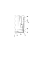
- the tip edge 42 a of the electrode attachment portion 42 is supported by the bottom portion 11 a of the case body 11. More specifically, for example, as shown in FIG. 1 and FIG. 3A, a cap-like insulator (spacer) 50 is placed on the distal end portion 42 b of the electrode attachment portion 42. Accordingly, the electrode attachment portion 42 (the front end edge 42a) is supported by the bottom portion 11a of the case body 11 while ensuring insulation with the case body 11.
- the electrode attachment portion 42 (the front end edge 42a) is not shown, but the case main body 11 is interposed via an insulating spacer or an insulating coat disposed between the front end edge 42a and the bottom portion 11a of the case main body 11. Is supported by the bottom 11a.
- interval is provided between the front-end
- the electrode attachment portion 42 includes an opening 42d between the base end portion 42c connected to the intermediate portion 43 and the tip end portion 42b. Both ends of the opening 42d are cut out into a ⁇ shape and a V shape in the drawing.
- retaining holes 42e having a C shape (a downward C shape and an upward C shape in the drawing), 42f is provided.
- a retaining hole (hereinafter referred to as “upper retaining hole”) 42e on the base end part 42c side is made smaller than a retaining hole (hereinafter referred to as “lower retaining hole”) 42f on the distal end part 42b side.
- the strength around the upper retaining hole 42e is higher than the strength around the lower retaining hole 42f.
- Two protrusions 42g and 42g are provided protruding from both edges of the opening 42d in the same direction as the internal connection portion 41.
- the opening 42d and the protrusions 42g and 42g are formed by, for example, making a cut in the length direction in the state of the strip before forming the electrode attachment portion 42 and raising both sides of the cut. Prior to raising both sides of the cut, the C-shaped upper and lower retaining holes 42e and 42f are formed so that the strip is not torn.
- the raised ridges 42g and 42g are closer to the inner side than both side edges of the electrode attachment portion 42. For this reason, the upper and lower end portions of the electrode attachment portion 42 are deformed into a W shape and an inverted W shape in the drawing. However, the protruding ridges 42g and 42g may not be moved inward, and both end portions of the electrode attachment portion 42 may be formed into an inverted M shape and an M shape.
- each protrusion 42g, 42g are twisted by the ⁇ -shaped and V-shaped notches of the opening 42d.
- the opening angle of the ⁇ -shaped notch on the base end part 42c side is made smaller than the opening angle of the V-shaped notch on the tip end part 42b side, and the protrusions 42g and 42g on the base end part 42c side
- the twisted state is made smaller than the twisted state of the protrusions 42g and 42g on the tip end portion 42b side.
- the base end portion 42c side of the electrode attachment portion 42 has higher strength than the tip end portion 42b side.
- the intermediate part 43 has a spring property so that vibration can be absorbed. As shown in FIG. 2A, the spring property is imparted by providing an arcuate portion 43a.
- the power generation element 20 is not suspended from the battery case 10 by the current collector 40 but is fixed to the battery case 10 by the current collector 40. Yes. Further, the intermediate portion 43 of the current collector 40 is provided with a spring property. For this reason, even if vibration is applied to the battery, the power generation element 20 does not vibrate with an amplitude or frequency different from that of the battery case 10 or vibrates with an amplitude or frequency in a range where there is no problem. Therefore, when vibration is applied to the battery, stress is generated in a portion of the current collector 40 (electrode attachment portion 42) connected to the power generating element 20 or a bent portion (intermediate portion 43). These parts do not break.
- the parameter of the portion that becomes the maximum acceleration is raised to 8, 10, 12, 15, 18, 20, 22G sequentially and repeated.
- the current collector 40 did not break in the battery according to the first embodiment shown in FIG.
- the twisted state of the protrusions 42g, 42g on the base end part 42c side is made smaller than the twisted state of the protrusions 42g, 42g on the distal end part 42b side, and / or
- the upper retaining hole 42e is made smaller than the lower retaining hole 42f, and / or the width of the electrode attachment portion 42 on the base end portion 42c side is wider than the width of the electrode attachment portion 42 on the distal end portion 42b side.
- the base end portion 42c side of the electrode attachment portion 42 is made stronger than the distal end portion 42b side of the electrode attachment portion 42, and the tip end portion 42b side of the electrode attachment portion 42 is broken first. Therefore, the current collector 40 can be continuously used as a battery for a while because the distal end portion 42b side of the electrode attachment portion 42 is first broken and the proximal end portion 42c side of the electrode attachment portion 42 is not broken.
- the battery according to the first embodiment can be suitably used by being mounted on a vehicle such as an automobile or a train running on a fuel cell.
- the current collector 40 includes a positive current collector 40 that connects the power generation element 20 (the positive electrode plate 21 exposed from one end portion thereof, that is, the end portion of the positive electrode plate 21) and the positive electrode terminal 31, and the power generation element 20. (Negative electrode plate 22 exposed from the other end portion thereof, that is, the end portion of negative electrode plate 22) and negative electrode current collector 40 connecting negative electrode terminal 32. As shown in FIGS. 5 and 6, the current collector 40 is connected with the positive electrode terminal 31 or the negative electrode terminal 32 being caulked like a rivet, or the electrode terminals 31 and 32 are connected by welding.
- the current collector 40 is formed into a deformed L-shape when viewed from the front using a single metal material.
- the positive electrode current collector 40 is formed from aluminum or an aluminum alloy, and the negative electrode current collector 40 is formed from copper or a copper alloy.
- any current collector 40 may be formed of the same metal material.
- the internal connection portion 41 and the electrode attachment portion 42 are oriented in a right angle direction (L shape in front view) with the intermediate portion 43 as a fold.
- the internal connection portion 41 is disposed along the back surface of the lid body 12 of the battery case 10 while being insulated from the back surface of the lid body 12 of the battery case 10.
- a through hole 41 a into which the inner end portion of the positive electrode terminal 31 or the negative electrode terminal 32 is fitted is provided at the distal end portion of the internal connection portion 41.
- the electrode attachment portion 42 is disposed between the end portion of the power generation element 20 and the end plate portion 11 c of the case body 11. As shown in FIG. 6, the tip end portion 42 b of the electrode attachment portion 42 is bent outwardly opposite to the internal connection portion 41, that is, obliquely toward the end plate portion 11 c of the battery case 10. Thereby, the tip edge 42 a of the electrode attachment portion 42 is supported by the bottom portion 11 a of the case body 11. By doing so, the tip edge 42a of the electrode attachment portion 42 is also in contact with the end plate portion 11b of the case body 11 (via an insulator 50 described later), and becomes a stay. For this reason, the power generation element 20 can be supported in a stable state without the current collector 40 becoming unstable.
- a cap-like insulator (spacer) 50 is placed on the tip 42b of the electrode attachment portion 42. Accordingly, the electrode attachment portion 42 (the front end edge 42a) is supported by the bottom portion 11a of the case body 11 while ensuring insulation with the case body 11.
- the electrode attachment portion 42 (the front end edge 42a) is not shown, but the case main body 11 is interposed via an insulating spacer or an insulating coat disposed between the front end edge 42a and the bottom portion 11a of the case main body 11. Is supported by the bottom 11a.
- interval is provided between the front-end
- the electrode attachment portion 42 includes an opening 42d between the base end portion 42c connected to the intermediate portion 43 and the tip end portion 42b. Both ends of the opening 42d are cut out into a ⁇ shape and a V shape in the drawing.
- retaining holes 42e having a C shape (a downward C shape and an upward C shape in the drawing), 42f is provided.
- a retaining hole (hereinafter referred to as “upper retaining hole”) 42e on the base end part 42c side is made smaller than a retaining hole (hereinafter referred to as “lower retaining hole”) 42f on the distal end part 42b side.
- the strength around the upper retaining hole 42e is higher than the strength around the lower retaining hole 42f.
- Two protrusions 42g and 42g are provided protruding from both edges of the opening 42d in the same direction as the internal connection portion 41.
- the opening 42d and the protrusions 42g and 42g are formed by, for example, making a cut in the length direction in the state of the strip before forming the electrode attachment portion 42 and raising both sides of the cut. Prior to raising both sides of the cut, the C-shaped upper and lower retaining holes 42e and 42f are formed so that the strip is not torn.
- the raised ridges 42g and 42g are closer to the inner side than both side edges of the electrode attachment portion 42. For this reason, the upper and lower end portions of the electrode attachment portion 42 are deformed into a W shape and an inverted W shape in the drawing. However, the protruding ridges 42g and 42g may not be moved inward, and both end portions of the electrode attachment portion 42 may be formed into an inverted M shape and an M shape.
- each protrusion 42g, 42g are twisted by the ⁇ -shaped and V-shaped notches of the opening 42d.
- the opening angle of the ⁇ -shaped notch on the base end part 42c side is made smaller than the opening angle of the V-shaped notch on the tip end part 42b side, and the protrusions 42g and 42g on the base end part 42c side
- the twisted state is made smaller than the twisted state of the protrusions 42g and 42g on the tip end portion 42b side.
- the base end portion 42c side of the electrode attachment portion 42 has higher strength than the tip end portion 42b side.
- the intermediate part 43 has a spring property so that vibration can be absorbed. As shown in FIG. 5A, the spring property is imparted by providing an arcuate portion 43a.
- the power generation element 20 is not suspended from the battery case 10 by the current collector 40 but is fixed to the battery case 10 by the current collector 40. Yes. Further, the intermediate portion 43 of the current collector 40 is provided with a spring property. For this reason, even if vibration is applied to the battery, the power generation element 20 does not vibrate with an amplitude or frequency different from that of the battery case 10 or vibrates with an amplitude or frequency in a range where there is no problem. Therefore, when vibration is applied to the battery, stress is generated in a portion of the current collector 40 (electrode attachment portion 42) connected to the power generating element 20 or a bent portion (intermediate portion 43). These parts do not break.
- the parameter of the portion that becomes the maximum acceleration is raised to 8, 10, 12, 15, 18, 20, 22G sequentially and repeated.
- the current collector 40 did not break in the battery according to the second embodiment shown in FIG.
- the twisting of the protrusions 42g and 42g on the base end part 42c side is made smaller than the twisting of the protrusions 42g and 42g on the distal end part 42b side.
- the base portion 42c side of the installation portion 42 has a higher strength than the distal end portion 42b side of the electrode attachment portion 42.
- the upper retaining hole 42e is made smaller than the lower retaining hole 42f, and the strength of the electrode attachment portion 42 on the base end portion 42c side is made higher than the strength of the electrode attachment portion 42 on the distal end portion 42b side.
- the tip end portion 42b side of the electrode attachment portion 42 is broken first. Accordingly, the current collector 40 can be used as a battery for a while because the distal end portion 42b side of the electrode attachment portion 42 is broken first and the proximal end portion 42c side of the electrode attachment portion 42 is not broken.
- the battery according to the second embodiment can be suitably used by being mounted on a vehicle such as an automobile or a train running on a fuel cell.
- the current collector 40 includes a positive current collector 40 that connects the power generation element 20 (the positive electrode plate 21 exposed from one end portion thereof, that is, the end portion of the positive electrode plate 21) and the positive electrode terminal 31, and the power generation element 20. (Negative electrode plate 22 exposed from the other end portion thereof, that is, the end portion of negative electrode plate 22) and negative electrode current collector 40 connecting negative electrode terminal 32. As shown in FIGS. 8 and 9, the current collector 40 is connected with the positive electrode terminal 31 or the negative electrode terminal 32 being caulked like a rivet, or the electrode terminals 31 and 32 are connected by welding.
- the current collector 40 is formed into a deformed L-shape when viewed from the front using a single metal material.
- the positive electrode current collector 40 is formed from aluminum or an aluminum alloy, and the negative electrode current collector 40 is formed from copper or a copper alloy.
- any current collector 40 may be formed of the same metal material.
- the internal connection portion 41 and the electrode attachment portion 42 are oriented in a right angle direction (L shape in front view) with the intermediate portion 43 as a fold.
- the internal connection portion 41 is disposed along the back surface of the lid body 12 of the battery case 10 while being insulated from the back surface of the lid body 12 of the battery case 10.
- a through hole 41 a into which the inner end portion of the positive electrode terminal 31 or the negative electrode terminal 32 is fitted is provided at the distal end portion of the internal connection portion 41.
- the electrode attachment portion 42 is disposed between the end portion of the power generation element 20 and the end plate portion 11 c of the case body 11. As shown in FIG. 9, the tip end portion 42 b of the electrode attachment portion 42 is bent in the same inward direction as the internal connection portion 41, that is, toward the power generation element 20. Thereby, the front end edge 42a of the electrode attaching portion 42 is supported by the surface of the bottom portion 11a of the case body 11 (via an insulator 50 described later). By doing so, the tip end portion 42b of the electrode attachment portion 42 becomes like a stay in contact with the bottom portion 11a of the case body 11 over a wide area. For this reason, the power generation element 20 can be supported in a stable state without the current collector 40 becoming unstable.
- a cap-like insulator (spacer) 50 is placed on the tip 42b of the electrode attachment portion 42.
- the electrode attachment portion 42 (the front edge 42a thereof) is supported by the bottom portion 11a of the case body 11 while ensuring insulation with the case body 11.
- the front-end edge 42a of the electrode attachment part 42 does not stab and insert the insulator 50 between the bottom parts 11a of the case main body 11, the insulator 50 is not damaged.
- the tip end portion 42b of the electrode attachment portion 42 in an arc shape the bent portion can be prevented from piercing the insulator 50 and the insulator 50 can be prevented from being damaged.
- the electrode attachment portion 42 (the front end edge 42a) is not illustrated, but the case main body 11 is interposed via an insulating spacer or an insulating coat disposed between the front end edge 42a and the bottom portion 11a of the case main body 11. Is supported by the bottom 11a.
- interval is provided between the front-end
- This insulating spacer is not damaged because the tip edge 42a of the electrode attachment portion 42 and the bent portion are not pierced.
- the electrode attachment portion 42 includes an opening 42d between the base end portion 42c connected to the intermediate portion 43 and the tip end portion 42b. Both ends of the opening 42d are cut out into a ⁇ shape and a V shape in the drawing.
- retaining holes 42e having a C shape (a downward C shape and an upward C shape in the drawing), 42f is provided.
- a retaining hole (hereinafter referred to as “upper retaining hole”) 42e on the base end part 42c side is made smaller than a retaining hole (hereinafter referred to as “lower retaining hole”) 42f on the distal end part 42b side.
- the strength around the upper retaining hole 42e is higher than the strength around the lower retaining hole 42f.
- Two protrusions 42g and 42g are provided protruding from both edges of the opening 42d in the same direction as the internal connection portion 41.
- the opening 42d and the protrusions 42g and 42g are formed by, for example, making a cut in the length direction in the state of the strip before forming the electrode attachment portion 42 and raising both sides of the cut. Prior to raising both sides of the cut, the C-shaped upper and lower retaining holes 42e and 42f are formed so that the strip is not torn.
- the raised ridges 42g and 42g are closer to the inner side than both side edges of the electrode attachment portion 42. For this reason, the upper and lower end portions of the electrode attachment portion 42 are deformed into a W shape and an inverted W shape in the drawing. However, the protruding ridges 42g and 42g may not be moved inward, and both end portions of the electrode attachment portion 42 may be formed into an inverted M shape and an M shape.
- each protrusion 42g, 42g are twisted by the ⁇ -shaped and V-shaped notches of the opening 42d.
- the opening angle of the ⁇ -shaped notch on the base end part 42c side is made smaller than the opening angle of the V-shaped notch on the tip end part 42b side, and the protrusions 42g and 42g on the base end part 42c side
- the twisted state is made smaller than the twisted state of the protrusions 42g and 42g on the tip end portion 42b side.
- the base end portion 42c side of the electrode attachment portion 42 has higher strength than the tip end portion 42b side.
- the intermediate part 43 has a spring property so that vibration can be absorbed. As shown in FIG. 8A, the spring property is imparted by providing an arcuate portion 43a.
- the power generating element 20 is not suspended from the battery case 10 by the current collector 40 but is fixed to the battery case 10 by the current collector 40. Yes. Further, the intermediate portion 43 of the current collector 40 is provided with a spring property. For this reason, even if vibration is applied to the battery, the power generation element 20 does not vibrate with an amplitude or frequency different from that of the battery case 10 or vibrates with an amplitude or frequency in a range where there is no problem. Therefore, when vibration is applied to the battery, stress is generated in a portion of the current collector 40 (electrode attachment portion 42) connected to the power generating element 20 or a bent portion (intermediate portion 43). These parts do not break.
- the parameters of the maximum acceleration part are sequentially increased to 8, 10, 12, 15, 18, 20, 22G and repeated.
- the current collector 40 did not break in the battery according to the third embodiment shown in FIG.
- the twisting of the protrusions 42g and 42g on the base end part 42c side is made smaller than the twisting of the protrusions 42g and 42g on the distal end part 42b side.
- the base portion 42c side of the installation portion 42 has a higher strength than the distal end portion 42b side of the electrode attachment portion 42.
- the upper retaining hole 42e is made smaller than the lower retaining hole 42f, and the strength of the electrode attachment portion 42 on the base end portion 42c side is made higher than the strength of the electrode attachment portion 42 on the distal end portion 42b side.
- the tip end portion 42b side of the electrode attachment portion 42 is broken first. Accordingly, the current collector 40 can be used as a battery for a while because the distal end portion 42b side of the electrode attachment portion 42 is broken first and the proximal end portion 42c side of the electrode attachment portion 42 is not broken.
- the battery according to the third embodiment can be suitably used by being mounted on a vehicle such as an automobile or a train running on a fuel cell.
- the tip edge 42 a of the electrode attachment portion 42 may not necessarily be in contact with the end plate portion 11 c as long as it is supported by the bottom portion 11 a of the case body 11.
- the intermediate part 43 of the electrode attachment part 42 does not need to have a spring property.
- the current collector 40 is not limited to the one bent at a right angle at the intermediate portion 43, and may be one bent at an obtuse angle or an acute angle. Alternatively, the current collector 40 does not have a bent portion like the intermediate portion 43 and may extend straight from the inner surface of the lid body 12 toward the bottom portion 11 a of the case main body 11.
- the ⁇ -shaped angle on the base end portion 42c side and the V-shaped angle on the distal end portion 42b side may be the same.
- the C-shaped retaining holes 42e and 42f may have the same size.
- the width on the base end portion 42c side and the width on the tip end portion 42b side may be the same.
- the spring property of the intermediate portion 43 includes an inclined portion 43 b connected to the internal connection portion 41, and a bent portion 43 c between the inclined portion 43 b and the electrode attachment portion 42. And may be provided by connecting the two.
- the spring property of the intermediate portion 43 is a bent portion 43d connected to the internal connection portion 41, and a lateral direction provided between the bent portion 43d and the electrode attachment portion 42. It may be provided by connecting a U-shaped detour part 43e.
- the bypass portion 43e shown in FIG. 10 (b) is provided so as to protrude toward the internal connection portion 41 due to the space in the case body 11. Also good. Moreover, it is good also as what combined this detour part 43e and the inclination part 43b shown to Fig.10 (a). Furthermore, the intermediate part 43 may meander in a wave shape and be provided with a spring property.
- the end plate portion 11c of the case main body 11 is preferably formed to be narrow, but the case main body 11 may not necessarily include the narrow end plate portion depending on the use situation.
- the power storage element is not limited to a battery.
- the electric storage element may be a capacitor such as an electric double layer capacitor.
- the power storage element is not limited to a vehicle and is not intended to limit the application.
Landscapes
- Engineering & Computer Science (AREA)
- Chemical & Material Sciences (AREA)
- Chemical Kinetics & Catalysis (AREA)
- Electrochemistry (AREA)
- General Chemical & Material Sciences (AREA)
- Power Engineering (AREA)
- Microelectronics & Electronic Packaging (AREA)
- Manufacturing & Machinery (AREA)
- Connection Of Batteries Or Terminals (AREA)
- Sealing Battery Cases Or Jackets (AREA)
- Electric Double-Layer Capacitors Or The Like (AREA)
- Secondary Cells (AREA)
- Cell Separators (AREA)
- Electric Propulsion And Braking For Vehicles (AREA)
Abstract
Description
第1内面及び該第1内面と隣り合う第2内面を有するケースと、
該ケースの内部に収納される電極体であって、互いに絶縁された正極板と負極板とを含む電極体と、
前記ケースの外部に配置される電極端子と、
前記ケースの内部に収納され、前記電極体と前記電極端子とを電気的に接続する集電体とを備え、
前記集電体の先端部の先端縁は、前記ケースの前記第1内面に支えられる。
前記集電体の前記先端部の前記先端縁と前記ケースの前記第1内面との間に間隔が設けられ、
前記集電体は、該間隔にスペーサを備え、
前記集電体の前記先端部の前記先端縁は、該スペーサを介して前記ケースの前記第1内面に支えられる
ようにすることができる。
前記集電体は、前記電極体の端部と前記ケースの前記第2内面との間に配置される電極添設部であって、前記電極体の前記端部に電気的に接続される電極添設部を備え、
該電極添設部の先端部の先端縁が前記ケースの前記第1内面に支えられる
ようにすることができる。
前記集電体は、
前記電極端子と接続される内部接続部と、
前記電極体の端部と前記ケースの前記第2内面との間に配置される電極添設部であって、前記電極体の前記端部に電気的に接続される電極添設部と、
前記内部接続部と前記電極添設部との間に介在する中間部とを備え、
該中間部は、バネ性を有する
ようにすることができる。
前記電極添設部には、その電極添設部の長さ方向に沿って開口部が設けられ、
前記電極添設部は、該開口部のエッジに、前記電極体の前記端部に接続される突条を備える
ようにすることができる。
前記電極添設部は、前記電極添設部の基端部側における前記開口部の端部及び前記電極添設部の先端部側における前記開口部の端部のそれぞれに切欠きを備え、
前記電極添設部の前記基端部側における前記切欠きの開き角度は、前記電極添設部の前記先端部側における前記切欠きの開き角度よりも小さい
ようにすることができる。
前記切欠きは、前記切欠きの尖端部に留孔を備え、
前記電極添設部の前記基端部側における前記切欠きの前記留孔は、前記電極添設部の前記先端部側における前記切欠きの前記留孔よりも小さい
ようにすることができる。
第1内面及び該第1内面と隣り合う第2内面を有する電池ケースと、
該電池ケースの内部に収納される発電要素であって、互いに絶縁された正極板と負極板とを含む発電要素と、
電池ケースの外部に配置される電極端子と、
電池ケースの内部に収納され、発電要素と電極端子とを電気的に接続する集電体とを備え、
集電体の先端部の先端縁は、電池ケースの第1内面に支えられる。
集電体の先端部の先端縁と電池ケースの第1内面との間に間隔が設けられ、
集電体は、該間隔にスペーサを備え、
集電体の先端部の先端縁は、該スペーサを介して電池ケースの第1内面に支えられる
ようにすることができる。
集電体は、発電要素の端部と電池ケースの第2内面との間に配置される電極添設部であって、発電要素の端部に電気的に接続される電極添設部を備え、
該電極添設部の先端部の先端縁が電池ケースの第1内面に支えられる
ようにすることができる。
集電体は、
電極端子と接続される内部接続部と、
発電要素の端部と電池ケースの第2内面との間に配置される電極添設部であって、発電要素の端部に電気的に接続される電極添設部と、
内部接続部と電極添設部との間に介在する中間部とを備え、
該中間部は、バネ性を有する
ようにすることができる。
電極添設部には、その電極添設部の長さ方向に沿って開口部が設けられ、
電極添設部は、該開口部のエッジに、発電要素の端部に接続される突条を備える
ようにすることができる。
電極添設部は、電極添設部の基端部側における開口部の端部及び電極添設部の先端部側における開口部の端部のそれぞれに切欠きを備え、
電極添設部の基端部側における切欠きの開き角度は、電極添設部の先端部側における切欠きの開き角度よりも小さい
ようにすることができる。
切欠きは、切欠きの尖端部に留孔を備え、
電極添設部の基端部側における切欠きの留孔は、電極添設部の先端部側における切欠きの留孔よりも小さい
ようにすることができる。
次に、本実施形態に係る電池の第1実施形態について、図1~図3を参照しながら詳細に説明する。
次に、本実施形態に係る電池の第2実施形態について、図4~図6を参酌しながら詳細に説明する。なお、電池ケース10、発電要素20及び電極端子31,32に関する記載は、第1実施形態における記載を援用する。
次に、本実施形態に係る電池の第3実施形態について、図7~図9を参酌しながら詳細に説明する。なお、電池ケース10、発電要素20及び電極端子31,32に関する記載は、第1実施形態における記載を援用する。
11……ケース本体
11a…底部
11c…端板部
12……蓋体
20……発電要素
31……電極端子
32……電極端子
40……集電体
41……内部接続部
42……電極添設部
42a…先端縁
42b…先端部
42c…基端部
42d…開口部
42e…留孔
42f…留孔
42g…突条
43……中間部
Claims (14)
- 第1内面及び該第1内面と隣り合う第2内面を有するケースと、
該ケースの内部に収納される電極体であって、互いに絶縁された正極板と負極板とを含む電極体と、
前記ケースの外部に配置される電極端子と、
前記ケースの内部に収納され、前記電極体と前記電極端子とを電気的に接続する集電体とを備え、
前記集電体の先端部の先端縁は、前記ケースの前記第1内面に支えられる
蓄電素子。 - 前記集電体の前記先端部は、前記ケースの前記第2内面と接するように屈曲される請求項1に記載の蓄電素子。
- 前記集電体の前記先端部は、前記ケースの前記第1内面に沿うように屈曲される請求項1に記載の蓄電素子。
- 前記集電体の前記先端部の前記先端縁は、前記ケースの前記第1内面と接することにより、前記ケースの前記第1内面に支えられる請求項1乃至請求項3のいずれか1項に記載の蓄電素子。
- 前記集電体の前記先端部の前記先端縁と前記ケースの前記第1内面との間に間隔が設けられ、
前記集電体は、該間隔にスペーサを備え、
前記集電体の前記先端部の前記先端縁は、該スペーサを介して前記ケースの前記第1内面に支えられる
請求項1乃至請求項3のいずれか1項に記載の蓄電素子。 - 前記スペーサは、絶縁性を有する請求項5に記載の蓄電素子。
- 前記集電体は、前記電極体の端部と前記ケースの前記第2内面との間に配置される電極添設部であって、前記電極体の前記端部に電気的に接続される電極添設部を備え、
該電極添設部の先端部の先端縁が前記ケースの前記第1内面に支えられる
請求項1乃至請求項6のいずれか1項に記載の蓄電素子。 - 前記集電体は、
前記電極端子と接続される内部接続部と、
前記電極体の端部と前記ケースの前記第2内面との間に配置される電極添設部であって、前記電極体の前記端部に電気的に接続される電極添設部と、
前記内部接続部と前記電極添設部との間に介在する中間部とを備え、
該中間部は、バネ性を有する
請求項1乃至請求項6のいずれか1項に記載の蓄電素子。 - 前記電極添設部には、その電極添設部の長さ方向に沿って開口部が設けられ、
前記電極添設部は、該開口部のエッジに、前記電極体の前記端部に接続される突条を備える
請求項7又は請求項8に記載の蓄電素子。 - 前記電極添設部の基端部側における強度は、前記電極添設部の先端部側における強度よりも高い請求項7乃至請求項9のいずれか1項に記載の蓄電素子。
- 前記電極添設部は、前記電極添設部の基端部側における前記開口部の端部及び前記電極添設部の先端部側における前記開口部の端部のそれぞれに切欠きを備え、
前記電極添設部の前記基端部側における前記切欠きの開き角度は、前記電極添設部の前記先端部側における前記切欠きの開き角度よりも小さい
請求項9に記載の蓄電素子。 - 前記切欠きは、前記切欠きの尖端部に留孔を備え、
前記電極添設部の前記基端部側における前記切欠きの前記留孔は、前記電極添設部の前記先端部側における前記切欠きの前記留孔よりも小さい
請求項11に記載の蓄電素子。 - 前記電極添設部の基端部側における幅は、前記電極添設部の先端部側における幅よりも広い請求項7乃至請求項12のいずれか1項に記載の蓄電素子。
- 請求項1乃至請求項13のいずれか1項に記載の蓄電素子を備える車両。
Priority Applications (5)
| Application Number | Priority Date | Filing Date | Title |
|---|---|---|---|
| JP2012549720A JP5913132B2 (ja) | 2010-12-20 | 2011-12-08 | 集電体を備える蓄電素子及びこの蓄電素子を備える車両 |
| DE112011104455T DE112011104455T5 (de) | 2010-12-20 | 2011-12-08 | Elektrische Speichervorrichtung mit Stromkollektor und Fahrzeug mit der elektrischen Speichervorrichtung |
| US13/989,042 US9514895B2 (en) | 2010-12-20 | 2011-12-08 | Electric storage device having current collector and vehicle having the electric storage device |
| CN201180050434.7A CN103238235B (zh) | 2010-12-20 | 2011-12-08 | 具备集电体的蓄电元件及具备该蓄电元件的车辆 |
| KR1020137010726A KR101893230B1 (ko) | 2010-12-20 | 2011-12-08 | 집전체를 구비하는 축전 소자 및 이 축전 소자를 구비하는 차량 |
Applications Claiming Priority (8)
| Application Number | Priority Date | Filing Date | Title |
|---|---|---|---|
| JP2010-282842 | 2010-12-20 | ||
| JP2010282845 | 2010-12-20 | ||
| JP2010-282845 | 2010-12-20 | ||
| JP2010282838 | 2010-12-20 | ||
| JP2010-282838 | 2010-12-20 | ||
| JP2010-282840 | 2010-12-20 | ||
| JP2010282840 | 2010-12-20 | ||
| JP2010282842 | 2010-12-20 |
Publications (1)
| Publication Number | Publication Date |
|---|---|
| WO2012086427A1 true WO2012086427A1 (ja) | 2012-06-28 |
Family
ID=46313707
Family Applications (1)
| Application Number | Title | Priority Date | Filing Date |
|---|---|---|---|
| PCT/JP2011/078456 Ceased WO2012086427A1 (ja) | 2010-12-20 | 2011-12-08 | 集電体を備える蓄電素子及びこの蓄電素子を備える車両 |
Country Status (6)
| Country | Link |
|---|---|
| US (1) | US9514895B2 (ja) |
| JP (2) | JP5913132B2 (ja) |
| KR (1) | KR101893230B1 (ja) |
| CN (1) | CN103238235B (ja) |
| DE (1) | DE112011104455T5 (ja) |
| WO (1) | WO2012086427A1 (ja) |
Cited By (2)
| Publication number | Priority date | Publication date | Assignee | Title |
|---|---|---|---|---|
| WO2012176704A1 (ja) * | 2011-06-24 | 2012-12-27 | 日立ビークルエナジー株式会社 | 二次電池 |
| JP2015222663A (ja) * | 2014-05-23 | 2015-12-10 | 日立オートモティブシステムズ株式会社 | 角形二次電池 |
Families Citing this family (14)
| Publication number | Priority date | Publication date | Assignee | Title |
|---|---|---|---|---|
| JP3248630B2 (ja) | 1991-10-02 | 2002-01-21 | 松下電器産業株式会社 | 水晶片の直接接合方法ならびにその方法を用いてなる水晶振動子,水晶発振器および水晶フィルタ |
| US9514895B2 (en) * | 2010-12-20 | 2016-12-06 | Gs Yuasa International Ltd. | Electric storage device having current collector and vehicle having the electric storage device |
| DE102014201160A1 (de) * | 2014-01-23 | 2015-07-23 | Robert Bosch Gmbh | Batteriezelle mit mindestens einem Elektrodenensemble |
| DE102014202337A1 (de) * | 2014-02-10 | 2015-08-13 | Robert Bosch Gmbh | Gehäuse mit verbesserter Wärmeleitung |
| KR102226515B1 (ko) * | 2014-06-17 | 2021-03-11 | 삼성에스디아이 주식회사 | 전극 조립체 및 이를 포함하는 이차 전지 |
| TW201731603A (zh) * | 2016-03-02 | 2017-09-16 | Dijiya Energy Saving Tech Inc | 鋰電池之導電連接片及其成型方法 |
| CN115152086B (zh) * | 2020-03-11 | 2025-05-06 | 株式会社东芝 | 连接引线和电池 |
| JP7514712B2 (ja) * | 2020-09-23 | 2024-07-11 | 株式会社豊田自動織機 | 蓄電装置 |
| CN215266587U (zh) * | 2021-06-30 | 2021-12-21 | 宁德时代新能源科技股份有限公司 | 集流构件、电池单体、电池以及用电装置 |
| USD1110945S1 (en) * | 2022-10-07 | 2026-02-03 | Gs Yuasa International Ltd. | Battery |
| USD1112046S1 (en) * | 2022-10-07 | 2026-02-10 | Gs Yuasa International Ltd. | Battery |
| USD1123824S1 (en) | 2023-06-01 | 2026-04-28 | Gs Yuasa International Ltd. | Battery |
| USD1123823S1 (en) | 2023-06-01 | 2026-04-28 | Gs Yuasa International Ltd. | Battery |
| US20260005408A1 (en) * | 2024-07-01 | 2026-01-01 | Sk On Co., Ltd. | Battery cell and battery module including the same |
Citations (7)
| Publication number | Priority date | Publication date | Assignee | Title |
|---|---|---|---|---|
| JPH10189055A (ja) * | 1996-12-27 | 1998-07-21 | Sony Corp | 二次電池 |
| JP2000150306A (ja) * | 1998-11-12 | 2000-05-30 | Toyota Motor Corp | 電池またはキャパシタの集電方式 |
| JP2006012830A (ja) * | 2004-06-23 | 2006-01-12 | Samsung Sdi Co Ltd | 二次電池 |
| JP2007149353A (ja) * | 2005-11-24 | 2007-06-14 | Sanyo Electric Co Ltd | 角形電池 |
| JP2008251260A (ja) * | 2007-03-29 | 2008-10-16 | Sanyo Electric Co Ltd | 電池及び電池の製造方法 |
| JP2010231945A (ja) * | 2009-03-26 | 2010-10-14 | Eliiy Power Co Ltd | 二次電池および二次電池の製造方法 |
| JP2010257945A (ja) * | 2009-04-21 | 2010-11-11 | Sb Limotive Co Ltd | 2次電池 |
Family Cites Families (30)
| Publication number | Priority date | Publication date | Assignee | Title |
|---|---|---|---|---|
| JP3075974B2 (ja) | 1995-03-13 | 2000-08-14 | 日本碍子株式会社 | 高温電池用断熱容器 |
| JP2001119801A (ja) | 1999-10-19 | 2001-04-27 | Yamaha Motor Co Ltd | 電動車両用制御ユニット |
| JP4233714B2 (ja) | 1999-10-19 | 2009-03-04 | ヤマハ発動機株式会社 | 電動車両用バッテリ冷却構造 |
| JP4712152B2 (ja) | 2000-04-18 | 2011-06-29 | パナソニック株式会社 | 角形電池及びその製造方法 |
| JP5034135B2 (ja) * | 2000-09-22 | 2012-09-26 | 株式会社デンソー | 電池およびその製造方法 |
| JP2002157984A (ja) | 2000-11-21 | 2002-05-31 | Shin Kobe Electric Mach Co Ltd | 組電池及び電池モジュール |
| JP4504600B2 (ja) | 2000-11-30 | 2010-07-14 | パナソニック株式会社 | 角形密閉式電池及びその製造方法 |
| JP5157027B2 (ja) | 2001-01-31 | 2013-03-06 | 株式会社Gsユアサ | 電池 |
| JP2002319388A (ja) | 2001-04-19 | 2002-10-31 | Toyota Motor Corp | 電池、組電池および端子 |
| JP4091769B2 (ja) | 2001-08-06 | 2008-05-28 | 松下電器産業株式会社 | 角形密閉式電池 |
| JP4061938B2 (ja) | 2001-12-20 | 2008-03-19 | トヨタ自動車株式会社 | 蓄電素子およびその製造方法 |
| JP4056279B2 (ja) * | 2002-03-29 | 2008-03-05 | 松下電器産業株式会社 | 電池 |
| JP4292365B2 (ja) | 2002-05-27 | 2009-07-08 | 株式会社ジーエス・ユアサコーポレーション | 電池 |
| JP2003093402A (ja) | 2002-07-25 | 2003-04-02 | Olympus Optical Co Ltd | 手術器械 |
| JP2005032477A (ja) | 2003-07-08 | 2005-02-03 | Toyota Motor Corp | 電池、およびそれを搭載した自動車 |
| JP4514434B2 (ja) * | 2003-11-06 | 2010-07-28 | 三洋電機株式会社 | 二次電池 |
| KR100612364B1 (ko) | 2004-10-28 | 2006-08-16 | 삼성에스디아이 주식회사 | 이차 전지 |
| JP4553751B2 (ja) | 2005-02-25 | 2010-09-29 | 三洋電機株式会社 | 角型二次電池 |
| JP4532448B2 (ja) | 2005-10-26 | 2010-08-25 | パナソニックEvエナジー株式会社 | 角形電池用電極ユニット、角形電池および角形電池用電極ユニットの製造方法 |
| JP5141026B2 (ja) | 2006-02-27 | 2013-02-13 | トヨタ自動車株式会社 | 蓄電パックの車載構造 |
| JP4918997B2 (ja) | 2006-04-27 | 2012-04-18 | 株式会社デンソー | 非水電解質二次電池 |
| JP2009037818A (ja) | 2007-08-01 | 2009-02-19 | Toyota Motor Corp | 電池 |
| JP2009110751A (ja) | 2007-10-29 | 2009-05-21 | Panasonic Corp | 二次電池 |
| JP5091060B2 (ja) | 2007-11-21 | 2012-12-05 | 本田技研工業株式会社 | 車両用電源装置 |
| JP5165482B2 (ja) | 2008-07-11 | 2013-03-21 | 日立ビークルエナジー株式会社 | 捲回式二次電池 |
| JP2010245221A (ja) | 2009-04-03 | 2010-10-28 | Panasonic Corp | キャパシタ及びこれを用いたキャパシタ装置 |
| JP5476794B2 (ja) * | 2009-05-20 | 2014-04-23 | 株式会社Gsユアサ | 電池 |
| JP2010284984A (ja) | 2009-06-09 | 2010-12-24 | Fuji Heavy Ind Ltd | 車両用バッテリ搭載構造 |
| JP5334894B2 (ja) * | 2010-03-12 | 2013-11-06 | 日立ビークルエナジー株式会社 | リチウムイオン二次電池 |
| US9514895B2 (en) * | 2010-12-20 | 2016-12-06 | Gs Yuasa International Ltd. | Electric storage device having current collector and vehicle having the electric storage device |
-
2011
- 2011-12-08 US US13/989,042 patent/US9514895B2/en active Active
- 2011-12-08 JP JP2012549720A patent/JP5913132B2/ja active Active
- 2011-12-08 WO PCT/JP2011/078456 patent/WO2012086427A1/ja not_active Ceased
- 2011-12-08 KR KR1020137010726A patent/KR101893230B1/ko active Active
- 2011-12-08 DE DE112011104455T patent/DE112011104455T5/de active Pending
- 2011-12-08 CN CN201180050434.7A patent/CN103238235B/zh active Active
-
2016
- 2016-03-29 JP JP2016066453A patent/JP6227040B2/ja active Active
Patent Citations (7)
| Publication number | Priority date | Publication date | Assignee | Title |
|---|---|---|---|---|
| JPH10189055A (ja) * | 1996-12-27 | 1998-07-21 | Sony Corp | 二次電池 |
| JP2000150306A (ja) * | 1998-11-12 | 2000-05-30 | Toyota Motor Corp | 電池またはキャパシタの集電方式 |
| JP2006012830A (ja) * | 2004-06-23 | 2006-01-12 | Samsung Sdi Co Ltd | 二次電池 |
| JP2007149353A (ja) * | 2005-11-24 | 2007-06-14 | Sanyo Electric Co Ltd | 角形電池 |
| JP2008251260A (ja) * | 2007-03-29 | 2008-10-16 | Sanyo Electric Co Ltd | 電池及び電池の製造方法 |
| JP2010231945A (ja) * | 2009-03-26 | 2010-10-14 | Eliiy Power Co Ltd | 二次電池および二次電池の製造方法 |
| JP2010257945A (ja) * | 2009-04-21 | 2010-11-11 | Sb Limotive Co Ltd | 2次電池 |
Cited By (4)
| Publication number | Priority date | Publication date | Assignee | Title |
|---|---|---|---|---|
| WO2012176704A1 (ja) * | 2011-06-24 | 2012-12-27 | 日立ビークルエナジー株式会社 | 二次電池 |
| JP2013008559A (ja) * | 2011-06-24 | 2013-01-10 | Hitachi Vehicle Energy Ltd | 二次電池 |
| US9252453B2 (en) | 2011-06-24 | 2016-02-02 | Hitachi Automotive Systems, Ltd. | Rechargeable battery |
| JP2015222663A (ja) * | 2014-05-23 | 2015-12-10 | 日立オートモティブシステムズ株式会社 | 角形二次電池 |
Also Published As
| Publication number | Publication date |
|---|---|
| US20130252080A1 (en) | 2013-09-26 |
| CN103238235B (zh) | 2016-08-10 |
| US9514895B2 (en) | 2016-12-06 |
| KR101893230B1 (ko) | 2018-08-29 |
| CN103238235A (zh) | 2013-08-07 |
| JP2016192403A (ja) | 2016-11-10 |
| DE112011104455T5 (de) | 2013-09-19 |
| KR20140027053A (ko) | 2014-03-06 |
| JP5913132B2 (ja) | 2016-04-27 |
| JPWO2012086427A1 (ja) | 2014-05-22 |
| JP6227040B2 (ja) | 2017-11-08 |
Similar Documents
| Publication | Publication Date | Title |
|---|---|---|
| JP6227040B2 (ja) | 集電体を備える蓄電素子及びこの蓄電素子を備える車両 | |
| JP5673355B2 (ja) | 電池 | |
| JP5618515B2 (ja) | 電池 | |
| JP5717008B2 (ja) | 集電部材を備える蓄電素子及び集電部材の製造方法 | |
| JP6225421B2 (ja) | 蓄電素子、及び、蓄電素子の製造方法 | |
| WO2016093338A1 (ja) | 蓄電素子 | |
| JPWO2013125271A1 (ja) | 蓄電素子 | |
| JP2010161075A (ja) | 電池モジュール | |
| JP6729137B2 (ja) | 二次電池及びその製造方法、並びにそれを用いた組電池 | |
| JP2013258039A (ja) | 蓄電素子及び導電性部材 | |
| JP2016189246A (ja) | 角形二次電池 | |
| JP2017068968A (ja) | 角形二次電池 | |
| JP2023013136A (ja) | 端子部品および端子部品の製造方法 | |
| JP2018206506A (ja) | 角形二次電池、それを用いた組電池及び車両 | |
| JP2017068967A (ja) | 角形二次電池 | |
| JP2018101568A (ja) | 角形二次電池及びその製造方法 | |
| JP5592844B2 (ja) | 蓄電素子 | |
| JP2019029226A (ja) | 蓄電素子の製造方法 | |
| JPWO2013168466A1 (ja) | 蓄電素子 | |
| JP5892226B2 (ja) | 電池 | |
| US20140255767A1 (en) | Energy storage device | |
| JP2018101569A (ja) | 角形二次電池及びその製造方法 | |
| JP5680480B2 (ja) | 電池 | |
| JP7096980B2 (ja) | 電池の製造方法 | |
| JP7161676B2 (ja) | 電池 |
Legal Events
| Date | Code | Title | Description |
|---|---|---|---|
| 121 | Ep: the epo has been informed by wipo that ep was designated in this application |
Ref document number: 11850844 Country of ref document: EP Kind code of ref document: A1 |
|
| ENP | Entry into the national phase |
Ref document number: 2012549720 Country of ref document: JP Kind code of ref document: A |
|
| ENP | Entry into the national phase |
Ref document number: 20137010726 Country of ref document: KR Kind code of ref document: A |
|
| WWE | Wipo information: entry into national phase |
Ref document number: 13989042 Country of ref document: US |
|
| WWE | Wipo information: entry into national phase |
Ref document number: 112011104455 Country of ref document: DE Ref document number: 1120111044550 Country of ref document: DE |
|
| 122 | Ep: pct application non-entry in european phase |
Ref document number: 11850844 Country of ref document: EP Kind code of ref document: A1 |