WO2012081286A1 - 車両、及びその走行装置 - Google Patents
車両、及びその走行装置 Download PDFInfo
- Publication number
- WO2012081286A1 WO2012081286A1 PCT/JP2011/070394 JP2011070394W WO2012081286A1 WO 2012081286 A1 WO2012081286 A1 WO 2012081286A1 JP 2011070394 W JP2011070394 W JP 2011070394W WO 2012081286 A1 WO2012081286 A1 WO 2012081286A1
- Authority
- WO
- WIPO (PCT)
- Prior art keywords
- vehicle
- link
- vehicle body
- upper link
- lower link
- Prior art date
- Legal status (The legal status is an assumption and is not a legal conclusion. Google has not performed a legal analysis and makes no representation as to the accuracy of the status listed.)
- Ceased
Links
Images



Classifications
-
- B—PERFORMING OPERATIONS; TRANSPORTING
- B61—RAILWAYS
- B61F—RAIL VEHICLE SUSPENSIONS, e.g. UNDERFRAMES, BOGIES OR ARRANGEMENTS OF WHEEL AXLES; RAIL VEHICLES FOR USE ON TRACKS OF DIFFERENT WIDTH; PREVENTING DERAILING OF RAIL VEHICLES; WHEEL GUARDS, OBSTRUCTION REMOVERS OR THE LIKE FOR RAIL VEHICLES
- B61F5/00—Constructional details of bogies; Connections between bogies and vehicle underframes; Arrangements or devices for adjusting or allowing self-adjustment of wheel axles or bogies when rounding curves
- B61F5/26—Mounting or securing axle-boxes in vehicle or bogie underframes
- B61F5/30—Axle-boxes mounted for movement under spring control in vehicle or bogie underframes
-
- B—PERFORMING OPERATIONS; TRANSPORTING
- B61—RAILWAYS
- B61F—RAIL VEHICLE SUSPENSIONS, e.g. UNDERFRAMES, BOGIES OR ARRANGEMENTS OF WHEEL AXLES; RAIL VEHICLES FOR USE ON TRACKS OF DIFFERENT WIDTH; PREVENTING DERAILING OF RAIL VEHICLES; WHEEL GUARDS, OBSTRUCTION REMOVERS OR THE LIKE FOR RAIL VEHICLES
- B61F5/00—Constructional details of bogies; Connections between bogies and vehicle underframes; Arrangements or devices for adjusting or allowing self-adjustment of wheel axles or bogies when rounding curves
- B61F5/26—Mounting or securing axle-boxes in vehicle or bogie underframes
-
- B—PERFORMING OPERATIONS; TRANSPORTING
- B61—RAILWAYS
- B61B—RAILWAY SYSTEMS; EQUIPMENT THEREFOR NOT OTHERWISE PROVIDED FOR
- B61B13/00—Other railway systems
-
- B—PERFORMING OPERATIONS; TRANSPORTING
- B61—RAILWAYS
- B61F—RAIL VEHICLE SUSPENSIONS, e.g. UNDERFRAMES, BOGIES OR ARRANGEMENTS OF WHEEL AXLES; RAIL VEHICLES FOR USE ON TRACKS OF DIFFERENT WIDTH; PREVENTING DERAILING OF RAIL VEHICLES; WHEEL GUARDS, OBSTRUCTION REMOVERS OR THE LIKE FOR RAIL VEHICLES
- B61F5/00—Constructional details of bogies; Connections between bogies and vehicle underframes; Arrangements or devices for adjusting or allowing self-adjustment of wheel axles or bogies when rounding curves
- B61F5/02—Arrangements permitting limited transverse relative movements between vehicle underframe or bolster and bogie; Connections between underframes and bogies
-
- B—PERFORMING OPERATIONS; TRANSPORTING
- B61—RAILWAYS
- B61F—RAIL VEHICLE SUSPENSIONS, e.g. UNDERFRAMES, BOGIES OR ARRANGEMENTS OF WHEEL AXLES; RAIL VEHICLES FOR USE ON TRACKS OF DIFFERENT WIDTH; PREVENTING DERAILING OF RAIL VEHICLES; WHEEL GUARDS, OBSTRUCTION REMOVERS OR THE LIKE FOR RAIL VEHICLES
- B61F5/00—Constructional details of bogies; Connections between bogies and vehicle underframes; Arrangements or devices for adjusting or allowing self-adjustment of wheel axles or bogies when rounding curves
- B61F5/26—Mounting or securing axle-boxes in vehicle or bogie underframes
- B61F5/30—Axle-boxes mounted for movement under spring control in vehicle or bogie underframes
- B61F5/32—Guides, e.g. plates, for axle-boxes
- B61F5/325—The guiding device including swinging arms or the like to ensure the parallelism of the axles
-
- B—PERFORMING OPERATIONS; TRANSPORTING
- B61—RAILWAYS
- B61F—RAIL VEHICLE SUSPENSIONS, e.g. UNDERFRAMES, BOGIES OR ARRANGEMENTS OF WHEEL AXLES; RAIL VEHICLES FOR USE ON TRACKS OF DIFFERENT WIDTH; PREVENTING DERAILING OF RAIL VEHICLES; WHEEL GUARDS, OBSTRUCTION REMOVERS OR THE LIKE FOR RAIL VEHICLES
- B61F9/00—Rail vehicles characterised by means for preventing derailing, e.g. by use of guide wheels
-
- B—PERFORMING OPERATIONS; TRANSPORTING
- B62—LAND VEHICLES FOR TRAVELLING OTHERWISE THAN ON RAILS
- B62D—MOTOR VEHICLES; TRAILERS
- B62D1/00—Steering controls, i.e. means for initiating a change of direction of the vehicle
- B62D1/24—Steering controls, i.e. means for initiating a change of direction of the vehicle not vehicle-mounted
- B62D1/26—Steering controls, i.e. means for initiating a change of direction of the vehicle not vehicle-mounted mechanical, e.g. by a non-load-bearing guide
- B62D1/265—Steering controls, i.e. means for initiating a change of direction of the vehicle not vehicle-mounted mechanical, e.g. by a non-load-bearing guide especially adapted for guiding road vehicles carrying loads or passengers, e.g. in urban networks for public transportation
-
- B—PERFORMING OPERATIONS; TRANSPORTING
- B61—RAILWAYS
- B61F—RAIL VEHICLE SUSPENSIONS, e.g. UNDERFRAMES, BOGIES OR ARRANGEMENTS OF WHEEL AXLES; RAIL VEHICLES FOR USE ON TRACKS OF DIFFERENT WIDTH; PREVENTING DERAILING OF RAIL VEHICLES; WHEEL GUARDS, OBSTRUCTION REMOVERS OR THE LIKE FOR RAIL VEHICLES
- B61F5/00—Constructional details of bogies; Connections between bogies and vehicle underframes; Arrangements or devices for adjusting or allowing self-adjustment of wheel axles or bogies when rounding curves
- B61F5/50—Other details
Definitions
- the present invention relates to a traveling device disposed on a front side and a rear side of a lower part of a vehicle body, and a vehicle including the traveling device.
- a traveling device for a vehicle having traveling wheels formed from rubber tires is disclosed in, for example, Patent Document 1 below.
- the vehicle travel device described in Patent Document 1 is located on a front side or a rear side of a pair of travel tires, an axle that connects the pair of travel tires, an axle support that supports the axle, A suspension frame having a hanging portion extending downward, upper and lower links connecting the hanging portion of the suspension frame and the axle support, and an air spring disposed between the vehicle body and the axle support.
- the upper link and the lower link extend in the horizontal direction in parallel with each other, one end of each link is connected to the hanging part of the suspension frame by a pin connection, and the other end of each link is connected to the axle support. They are connected by pin connection.
- a parallel four-link mechanism is configured by the hanging portion of the suspension frame, the axle support, the upper link, and the lower link.
- the parallel four-link mechanism supports the axle support so that it can move up and down relatively with respect to the suspension frame and the vehicle body to which the suspension frame is attached. Further, in the above traveling device, the vertical movement of the axle support body caused by the vertical movement of the traveling tire and the axle due to the unevenness of the traveling road surface R is absorbed by the air spring.
- the upper link and the lower link both extend in the horizontal direction when the vehicle is stopped with no passengers.
- the axle support moves up and down as the traveling tire and axle move up and down.
- the upper link and the lower link are slightly inclined with respect to the horizontal direction.
- the inclination angle is about 0.5 °, and it can be said that it is in a state extending substantially in the horizontal direction.
- the traveling device described in Patent Document 1 has a problem that the vehicle body is inclined in the front-rear direction during acceleration / deceleration, and the ride comfort is not so good.
- an object of the present invention is to provide a vehicle capable of suppressing the inclination of the vehicle body during acceleration and deceleration and improving the riding comfort during acceleration and deceleration, and a traveling device for the vehicle.
- the vehicle travel device provides: In the vehicle traveling device disposed on the front side and the rear side of the lower part of the vehicle body, An axle support that supports an axle to which a traveling wheel is attached; a hanging portion that is disposed on the center side of the vehicle body with respect to the axle support and extends downward from the vehicle body; and the axle with respect to the hanging portion A link that couples the support so as to be relatively displaceable in the vertical direction.
- the link is disposed above the lower link with a lower link connected to the hanging part and the axle support by a pin connection, and connected to the hanging part and the axle support by a pin connection. And a link.
- the position where the lower link is connected to the axle support body by pin connection is positioned below the position where the lower link of the suspension frame is connected by pin connection in the vertical direction. Further, in the vertical direction, when the distance from the position where the lower link is connected to the hanging part by pin coupling to the position where the lower link is connected to the axle support body by pin coupling is the vertical distance, the upper link However, the position where the lower link is connected to the axle support body by pin connection is in the vertical direction, and the position where the lower link is connected to the hanging part by pin connection is located in the lower distance range.
- the position where the upper link is connected to the axle support body by pin connection is in the vertical direction, and is the pin connection with the hanging part of the suspension frame.
- the position of the distance between the upper and lower sides may be lower than the connecting position.
- the position where the upper link is connected to the axle support body by pin connection may be the same position as the position where the upper link is connected to the hanging part of the suspension frame by pin connection.
- the vehicle according to the second aspect of the present invention is The vehicle body, the traveling device disposed at a lower front portion of the vehicle body, and the traveling device disposed at a rear lower portion of the vehicle body.
- a vertical component force is generated in the force acting on each link by the reaction force acting on the contact portion of the traveling wheel during acceleration / deceleration.
- This component force acts on the vehicle body as a moment in the opposite direction to the moment of inertia that tends to tilt the vehicle body in the front-rear direction during acceleration / deceleration.
- the inclination of the vehicle body in the front-rear direction during acceleration / deceleration can be suppressed, and the riding comfort can be improved.
- the vehicle of this embodiment is a vehicle of a new traffic system of a side guide rail type.
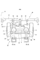
- This vehicle includes a vehicle body 1 and a traveling device.
- the traveling device includes a pair of left and right traveling tires 3, an axle 5 that connects the pair of traveling tires (running wheels) 3, and a suspension that supports the axle 5 and the pair of traveling tires 3.
- the apparatus 10 and the steering guide apparatus 20 which makes the driving
- the suspension device 10 is capable of displacing the carriage frame 11 in the vertical direction, a carriage frame (axle support) 11 that supports the axle 5, a pair of left and right air springs 19 disposed between the carriage frame 11 and the vehicle body 1. And a plurality of links 14a, 14b and a pair of left and right suspension frames 15.
- the bogie frame 11 has a main body 12 that is U-shaped in plan view. A hanging portion that hangs downward from each of the arm portions of the main body 12 forms a vehicle bearing 13.
- the axle 5 is attached to the vehicle bearing 13 of the bogie frame 11.
- Each of the pair of left and right suspension frames 15 is provided on the rear side of the vehicle bearing 13 and includes a hanging portion 16 that extends downward and a mounting portion 17 that extends from the upper end of the hanging portion 16 to the front of the vehicle.
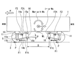
- the hanging portion 16 of the suspension frame 15, the bogie frame main body 12, and the vehicle bearing 13 are connected to each other by an upper link 14 a and a lower link 14 b that are aligned vertically and parallel to each other.
- One end of these links 14a and 14b is connected to the hanging part 16 of the suspension frame 15 by pin coupling, and the other end of these links 14a and 14b is connected to the bogie frame main body 12 and the vehicle bearing 13 and the pin. Connected with a bond.
- the position 11b where the lower link 14b and the vehicle bearing 13 are connected by pin connection is located below the position 15b where the lower link 14b and the hanging part 16 of the suspension frame 15 are connected by pin connection in the vertical direction. Yes.
- a distance from a position 11b where the lower link 14b and the vehicle bearing 13 are connected by pin coupling to a position 15b where the lower link 14b and the hanging part 16 are connected by pin coupling is defined as a vertical distance d.
- the position 11a where the upper link 14a and the carriage frame main body 12 are connected by pin connection is a vertical distance from the position 15a where the upper link 14a and the hanging part 16 are connected by pin connection in the vertical direction. It is located at the position of d.
- the position 11a where the upper link 14a and the carriage frame main body 12 are connected by pin connection is connected to the upper link 14a and the hanging part 16 of the suspension frame 15 by pin connection.
- the position 11b is located below the position 15a where the lower link 14b and the vehicle bearing 13 are coupled by pin coupling, and the position 11b is coupled by the pin coupling between the lower link 14b and the hanging part 16 of the suspension frame 15.
- the hanging portion 16 of the suspension frame 15, the bogie frame main body 12 and the vehicle bearing 13, and the two links 14a and 14b constitute a parallel four-link mechanism.
- the bogie frame main body 12 and the vehicle bearing 13 can move up and down without changing the direction of the suspension frame 15 relative to the hanging portion 16.
- the two links 14 a and 14 b also serve as traction rods for transmitting the driving force and deceleration force of the traveling tire 3 to the vehicle body 1.
- the air spring 19 is provided between the bogie frame main body 12 and the vehicle body 1. By providing the air spring 19, the relative vertical vibration of the traveling tire 3 and the axle 5 with respect to the vehicle body 1 is alleviated.
- the steering guide device 20 extends in the width direction of the vehicle body 1, a king pin (not shown) that constitutes a steering shaft of the traveling tire 3, a steering arm 28 that swings integrally with the traveling tire 3 with reference to this king pin,
- the carriage frame 11 is arranged such that the guide transverse beam 21 arranged on the rear side of the suspension device 10, the guide wheels 22 provided at both ends of the guide transverse beam 21, and the guide transverse beam 21 can be displaced in the width direction of the vehicle body 1.
- the forward / reverse switching device 23 and the turning arm 24 connected to the main body 12 of the vehicle and the one end of the steering arm 28 of the traveling tire 3 of the pair of left and right traveling tires 3 are coupled to the forward / reverse switching device 23.
- a connecting rod 25; and a tie rod 26 that connects the other end of the steering arm 28 of one traveling tire 3 and the end of the steering arm 28 of the other traveling tire 3.
- One end of the connecting rod 25 is connected to the forward / reverse switching device 23 by pin coupling, and the other end of the connecting rod 25 is connected to the steering arm 28 of one traveling tire 3 of the pair of left and right traveling tires 3. It is connected to one end by pin connection. Further, both end portions of the tie rod 26 are connected to the end portions of the respective steering arms 28 of the pair of traveling tires 3 by pin coupling.
- the guide rod 22 of the steering guide device 20 When the guide wheel 22 of the steering guide device 20 is in contact with the side guide rail G and receives a lateral load from the side guide rail G, the guide rod 22 is displaced in the vehicle width direction of the vehicle body 1.
- the displacement of the guide lateral beam 21 in the vehicle width direction is transmitted to the steering arm 28 of one traveling tire 3 via the forward / reverse switching device 23 and the connecting rod 25.
- the one running tire 3 and the steering arm 28 swing with respect to the kingpin.
- the swing of the steering arm 28 of one traveling tire 3 is transmitted to the steering arm 28 of the other traveling tire 3 via the tie rod 26.
- the other traveling tire 3 and the steering arm 28 also swing with respect to the kingpin, like the one traveling tire 3.
- the front-rear direction is reversed.
- the hanging portion 16 of the suspension frame is located on the rear side of the vehicle bearing 13 of the carriage frame 11.
- a hanging portion 16 of the suspension frame 15 is located on the front side of the bearing 13.
- both the upper link 14a and the lower link 14b have the front pin coupling positions 11a and 11b located below the rear pin coupling positions 15a and 15b.
- the rear-side pin coupling positions 11a and 11b are located below the front-side pin coupling positions 15a and 15b.
- the position 11a where the upper link 14a and the bogie frame main body 12 are connected by pin coupling is the upper link 14a and the suspension frame 15 in both the front traveling device and the rear traveling device.
- the lower link 14b also has an inclination angle ⁇ such that the position 11b where the lower link 14b and the vehicle bearing 13 are connected by pin connection is lower than the position 15b where the lower link 14b and the suspension frame 15 are connected by pin connection. Tilted.
- the inclination angles ⁇ of the upper link 14a and the lower link 14b are both values when the vehicle is stopped without a passenger.
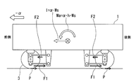
- FIG. 4A and FIG. 4B show the moment of inertia acting on the vehicle body in a conventional traveling device in which the upper link 14a and the lower link 14b are parallel to each other and both extend in the horizontal direction. It explains using. 4A shows a state during acceleration, and FIG. 4B shows a state during deceleration.
- the inertial force I acting on the vehicle body 1 when the vehicle is accelerating forward at an acceleration ⁇ can be expressed by the following equation.
- I - ⁇ ⁇ Ws Ws: Body weight (not including travel device)
- reaction force P acting on the ground contact portion of the traveling tire 3 at this time can be expressed by the following equation.
- P ⁇ ⁇ Wo (Single axis drive)
- P ⁇ ⁇ Wo / 2 (in the case of 2-axis drive)
- the moment of inertia Ma generated by the inertial force I acting on the vehicle body 1 can be expressed by the following equation.
- reaction force P acting on the ground contact portion of the traveling tire 3 at this time can be expressed by the following equation.
- P - ⁇ ⁇ Wo (Single axis drive)
- P - ⁇ ⁇ Wo / 2 (in the case of 2-axis drive)
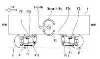
- FIG. 3A shows a state during acceleration
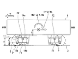
- FIG. 3B shows a state during deceleration.
- the tire reaction force moment Mt that cancels the inertia moment Ma and the inertia moment Ma that tries to tilt the vehicle body 1 in the front-rear direction also act on the vehicle body 1.
- the inclination of the vehicle body 1 at the time of acceleration / deceleration of the vehicle can be suppressed.
- the link inclination angle ⁇ is 0 ° when accelerating at an acceleration ⁇ , that is, in the case of a conventional traveling apparatus and the lifting amount of the front portion of the vehicle body 1 is 10 mm
- the inclination angle ⁇ of the upper link 14a and the lower link 14b with respect to the horizontal direction is preferably 5 ° or more and 15 ° or less as shown below. 5 ° ⁇ ⁇ ⁇ 15 °
- the inclination angle ⁇ is preferably 5 ° or more.
- the inclination angle ⁇ exceeds 15 °, the amount of movement in the front-rear direction associated with the movement of the traveling tire 3, the axle and the carriage frame relative to the suspension frame 15 in the up-and-down direction increases, and each link 14a, The unnecessary load which acts on the position where 14b connects by pin coupling becomes large.
- the inclination angle ⁇ is preferably 15 ° or less.
- FIGS. 5A and 5B show a state during acceleration
- FIG. 5B shows a state during deceleration.
- the traveling device of the present embodiment is basically the same configuration as the traveling device of the first embodiment except that the position where the upper link 14a is connected by pin coupling is different. Therefore, the points different from the first embodiment will be mainly described below.
- the lower link 14b of the present embodiment has a position 11b where the lower link 14b and the carriage frame 11 are connected by pin coupling, and the lower link 14b and the hanging part 16 of the suspension frame 15 are coupled by pin coupling. It is located below the connecting position 15b in the vertical direction and is inclined at an inclination angle ⁇ with respect to the horizontal direction.
- the upper link 14a of the present embodiment has a position 11a where the upper link 14a and the carriage frame 11 are connected by pin coupling, and a position 15a where the upper link 14a and the hanging part 16 are connected by pin coupling in the vertical direction. , In the same position.
- the upper link 14a extends in the horizontal direction and is provided with an inclination angle of 0 °.
- the inclination angle (however, 0 °) of the upper link 14a and the inclination angle ⁇ of the lower link 14b are both values when the vehicle is stopped in the absence of passengers.
- a vertical component force F1t of the force acting on the lower link 14b acts on the vehicle body 1 as a moment.
- This moment that is, the tire reaction force moment Mt can be expressed by the following equation.
- ⁇ B (A / b) ⁇ P ⁇ B ⁇ tan ⁇
- the vertical component force F1t of the force acting on the lower link 14b acts on the vehicle body 1 as a moment as in acceleration.
- This moment that is, the tire reaction force moment Mt can be expressed by the following equation.
- ⁇ B -(A / b) ⁇ P ⁇ B ⁇ tan ⁇
- the tire reaction force moment Mt in a direction to cancel the inertia moment Ma acts on the vehicle body 1 together with the inertia moment Ma that tries to tilt the vehicle body 1 in the front-rear direction during acceleration / deceleration of the vehicle. Therefore, the inclination of the vehicle body 1 at the time of acceleration / deceleration of the vehicle can be suppressed.
- the inclination angle ⁇ of the lower link 14b is preferably 3 ° or more and 10 ° or less as shown below.
- the inclination angle ⁇ is preferably 3 ° or more.
- the inclination angle ⁇ exceeds 10 °, the carriage frame 11 is inclined. Therefore, the inclination angle ⁇ is preferably 10 ° or less. This is because the traveling tire 3, the axle 5 and the bogie frame 11 move relative to the suspension frame 15 in the vertical direction at the lower portion of the bogie frame 11 connected to the inclined lower link 14b by pin coupling. This is because the amount of relative movement in the front-rear direction is larger than the amount of relative movement in the front-rear direction at the upper portion of the carriage frame 11 connected to the upper link 14a extending in the horizontal direction by pin coupling.
- the upper link 14a is not inclined, but may be inclined within the range of the inclination angle ⁇ of the lower link 14b.
- the upper link 14a has a vertical direction from a position 11a where the upper link 14a and the carriage frame 11 are coupled by pin coupling, and from a position 15a where the upper link 14a and the hanging portion 16 of the suspension frame 15 are coupled by pin coupling. Therefore, it may be tilted downward so as to be within the range of the above-described distance d between the upper and lower sides.
- each of the above embodiments is an example in which the present invention is applied to a vehicle of a new traffic system of a side guide rail type, but the present invention is not limited to this.
- Each of the above embodiments may be applied to, for example, a vehicle with a central guide rail type new transportation system, or may be applied to other vehicles.
- the inclination of the vehicle body in the front-rear direction during acceleration / deceleration can be suppressed, and the riding comfort can be improved.
Landscapes
- Engineering & Computer Science (AREA)
- Mechanical Engineering (AREA)
- Transportation (AREA)
- Chemical & Material Sciences (AREA)
- Combustion & Propulsion (AREA)
- Platform Screen Doors And Railroad Systems (AREA)
- Vehicle Body Suspensions (AREA)
Abstract
Description
上リンクと下リンクとは、互いに平行に水平方向に延びており、各リンクの一方の端部が懸架枠の垂下部にピン結合で連結し、各リンクの他方の端部が車軸支持体にピン結合で連結している。
車体の下部の前側及び後側にそれぞれ配置されている車両の走行装置において、
走行輪が取り付けられた車軸を支える車軸支持体と、前記車軸支持体を基準にして前記車体の中央側に配置され、前記車体から下方に延びる垂下部と、前記垂下部に対して、前記車軸支持体を上下方向に相対変位可能に、両者を連結するリンクと、を備える。
前記リンクは、前記垂下部及び前記車軸支持体のそれぞれにピン結合で連結する下リンクと、前記下リンクの上方に配置され、前記垂下部及び前記車軸支持体のそれぞれにピン結合で連結する上リンクと、を有する。また、前記下リンクが前記車軸支持体とピン結合で連結する位置は、上下方向で、前記懸架枠の前記垂下部とピン結合で連結する位置よりも下方に位置する。さらに、上下方向で、前記下リンクが前記垂下部とピン結合で連結する位置から前記下リンクが前記車軸支持体とピン結合で連結する位置までの距離を上下間距離とした場合、前記上リンクが前記車軸支持体とピン結合で連結する位置は、上下方向で、前記下リンクが前記垂下部とピン結合で連結する位置から、下側に前記上下間距離の範囲内に位置している。
前記車体と、前記車体の前側下部に配置されている前記走行装置と、前記車体の後側下部に配置されている前記走行装置と、を備えている。
まず、本発明に係る車両の走行装置の第一実施形態について、図1~図4Bを用いて説明する。
このため、車両の前側の走行装置では、例えば、台車枠11の車軸受13の後側に、懸架枠の垂下部16が位置しているが、後側の走行装置では、台車枠11の車軸受13の前側に、懸架枠15の垂下部16が位置している。また、前側の走行装置では、上リンク14a及び下リンク14bは、いずれも、前側のピン結合位置11a,11bが後側のピン結合位置15a,15bよりも下側に位置しているが、後側の走行装置では、上リンク及び下リンクは、いずれも、後側のピン結合位置11a,11bが前側のピン結合位置15a,15bよりも下側に位置している。
I=-α・Ws
Ws:車体重量(走行装置を含まない)
P=α・Wo (1軸駆動の場合)
P=α・Wo/2 (2軸駆動の場合)
F2=-P・c/b (∵c・P=-F2・b)
b:上リンクと台車枠本体とがピン結合で連結する位置と、下リンクと車軸受とがピン結合で連結する位置との間の距離、c:下リンクと車軸受とがピン結合で連結する位置と、接地面との間の距離
F1=P・a/b
(∵P=F1+F2、F1=-F2+P=P・c/b+P・b/b=P・(c+b)/b)
a:上リンクと台車枠本体とがピン結合で連結する位置と、接地面との間の距離
Ma=I・h=(-α・Ws)・h
=-α・h・Ws
h:空気バネの中間点と車体の重心との間の上下方向の距離
I=α・Ws
P=-α・Wo (1軸駆動の場合)
P=-α・Wo/2 (2軸駆動の場合)
F2=P・c/b
F1=-P・a/b
Ma=I・h=(α・Ws)・h
=α・h・Ws
F2t=F2・tanθ=(-P・c/b)・tanθ
F1t=F1・tanθ=(P・a/b)・tanθ
Mt=(F1t+F2t)・B
=〔(P・a/b)・tanθ+(-P・c/b)・tanθ〕・B
=〔(a-c)/b〕・P・B・tanθ
=P・B・tanθ (∵b=a-c)
B:前側走行装置の懸架枠の垂下部と後側走行装置の懸架枠の垂下部との間の距離
F2t=F2・tanθ=(P・c/b)・tanθ
F1t=F1・tanθ=(-P・a/b)・tanθ
Mt=(F1t+F2t)・B
=〔(-P・a/b)・tanθ+(P・c/b)・tanθ〕・B
=〔(-a+c)/b〕P・B・tanθ
=-P・B・tanθ (∵b=a-c)
5°≦θ≦15°
次に、本発明に係る車両の走行装置の第二実施形態について、図5A及び図5Bを用いて説明する。
なお、図5Aは加速時の状態を示し、図5Bは減速時の状態を示している。
F1t=F1・tanθ=(P・a/b)・tanθ
Mt=F1t・B
=〔(P・a/b)・tanθ〕・B
=(a/b)・P・B・tanθ
F1t=F1・tanθ=(-P・a/b)・tanθ
Mt=F1t・B
=〔(-P・a/b)・tanθ〕・B
=-(a/b)・P・B・tanθ
3:走行タイヤ(走行輪)
5:車軸
10:懸架装置
11:台車枠(車軸支持体)
13:(車軸支持体の)車軸受け
14a:上リンク
14b:下リンク
15:懸架枠
16:(懸架枠の)垂下部
17:(懸架枠の)取付部
19:空気バネ
11a:(台車枠と上リンクとの)ピン結合位置
11b:(台車枠と下リンクとの)ピン結合位置
15a:(懸架枠の垂下部と上リンクとの)ピン結合位置
15b:(懸架枠の垂下部と下リンクとの)ピン結合位置
20:操舵案内装置
Claims (4)
- 車体の下部であって、前記車体の前側及び後側にそれぞれ配置されている車両の走行装置において、
走行輪が取り付けられた車軸を支える車軸支持体と、
前記車軸支持体を基準にして前記車体の中央側に配置され、前記車体から下方に延びる垂下部と、
前記垂下部に対して、前記車軸支持体を上下方向に相対変位可能に、両者を連結するリンクと、
を備え、
前記リンクは、前記垂下部及び前記車軸支持体のそれぞれにピン結合で連結される下リンクと、前記下リンクの上方に配置され、前記垂下部及び前記車軸支持体のそれぞれにピン結合で連結される上リンクと、を有し、
前記下リンクは、前記下リンクと前記車軸支持体とのピン結合の位置が、前記下リンクと前記懸架枠の前記垂下部とのピン結合する位置よりも、上下方向で、下方に位置し、
前記下リンクと前記垂下部とのピン結合の位置から前記下リンクと前記車軸支持体とのピン結合の位置までの上下方向の距離を上下間距離とした場合、前記上リンクは、前記上リンクと前記車軸支持体とのピン結合の位置が、前記上リンクと前記垂下部とのピン結合の位置から、上下方向で、下側に前記上下間距離の範囲内に位置している車両の走行装置。 - 請求項1に記載の車両の走行装置において、
前記上リンクは、前記上リンクと前記車軸支持体とのピン結合の位置が、前記上リンクと前記懸架枠の前記垂下部とのピン結合の位置から、上下方向で、下側に前記上下間距離の位置に位置している車両の走行装置。 - 請求項1に記載の車両の走行装置において、
前記上リンクは、前記上リンクと前記車軸支持体とがピン結合で連結する位置が、前記上リンクと前記懸架枠の前記垂下部とがピン結合で連結する位置と、上下方向で、同じ位置に位置している
車両の走行装置。 - 前記車体と、
請求項1から3のいずれか一項に記載の走行装置と、
を備えている車両。
Priority Applications (4)
| Application Number | Priority Date | Filing Date | Title |
|---|---|---|---|
| SG2013007141A SG190676A1 (en) | 2010-12-17 | 2011-09-07 | Vehicle and travel device for same |
| KR1020127033090A KR101446855B1 (ko) | 2010-12-17 | 2011-09-07 | 차량 및 그 주행 장치 |
| CN2011800372761A CN103052550A (zh) | 2010-12-17 | 2011-09-07 | 车辆及其行驶装置 |
| US13/812,630 US9346474B2 (en) | 2010-12-17 | 2011-09-07 | Vehicle and travel device for same |
Applications Claiming Priority (2)
| Application Number | Priority Date | Filing Date | Title |
|---|---|---|---|
| JP2010281732A JP5297443B2 (ja) | 2010-12-17 | 2010-12-17 | 車両、及びその走行装置 |
| JP2010-281732 | 2010-12-17 |
Publications (1)
| Publication Number | Publication Date |
|---|---|
| WO2012081286A1 true WO2012081286A1 (ja) | 2012-06-21 |
Family
ID=46244401
Family Applications (1)
| Application Number | Title | Priority Date | Filing Date |
|---|---|---|---|
| PCT/JP2011/070394 Ceased WO2012081286A1 (ja) | 2010-12-17 | 2011-09-07 | 車両、及びその走行装置 |
Country Status (6)
| Country | Link |
|---|---|
| US (1) | US9346474B2 (ja) |
| JP (1) | JP5297443B2 (ja) |
| KR (1) | KR101446855B1 (ja) |
| CN (1) | CN103052550A (ja) |
| SG (1) | SG190676A1 (ja) |
| WO (1) | WO2012081286A1 (ja) |
Families Citing this family (5)
| Publication number | Priority date | Publication date | Assignee | Title |
|---|---|---|---|---|
| CN102282510B (zh) | 2009-01-14 | 2014-02-12 | 日本电产科宝株式会社 | 像抖动修正装置和具有像抖动修正装置的拍摄单元 |
| JP6383282B2 (ja) * | 2014-12-17 | 2018-08-29 | 川崎重工業株式会社 | 鉄道車両用台車 |
| JP7009936B2 (ja) | 2017-11-06 | 2022-01-26 | 株式会社デンソー | シフトレンジ制御装置 |
| CN114670888B (zh) * | 2022-04-25 | 2023-03-24 | 西南交通大学 | 一种列车脱轨后防脱线装置 |
| US12168383B2 (en) | 2022-11-30 | 2024-12-17 | Caterpillar Inc. | Retainer for pins to support axles under chassis of work machines |
Citations (7)
| Publication number | Priority date | Publication date | Assignee | Title |
|---|---|---|---|---|
| JPS4960416U (ja) * | 1972-09-06 | 1974-05-28 | ||
| JPS5323416A (en) * | 1976-08-14 | 1978-03-03 | Daimler Benz Ag | Traffic system with running channel and road vehicle guidable on the channel along track |
| JPS616061A (ja) * | 1984-06-18 | 1986-01-11 | 日本車輌製造株式会社 | 案内軌道車の走行装置 |
| JPS63305072A (ja) * | 1987-03-12 | 1988-12-13 | ウアゴン・ウニオン・ゲゼルシヤフト・ミト・ベシユレンクテル・ハフツング | 軌条車両用の空回り車輪を備えた一軸走行装置 |
| FR2675105A1 (fr) * | 1991-04-11 | 1992-10-16 | Matra Transport | Train de roulement pour vehicule circulant sur une voie de guidage. |
| JP2010188971A (ja) * | 2009-02-20 | 2010-09-02 | Mitsubishi Heavy Ind Ltd | ガイドレール式車両用台車 |
| JP2010215120A (ja) * | 2009-03-17 | 2010-09-30 | Mitsubishi Heavy Ind Ltd | 軌道系車両用台車 |
Family Cites Families (9)
| Publication number | Priority date | Publication date | Assignee | Title |
|---|---|---|---|---|
| DE2240075B1 (de) | 1972-08-16 | 1974-02-21 | Fa. Carl Zeiss, 7920 Heidenheim | Objektiv zur bilderzeugung auf der photokathode einer bildaufnahmeroehre |
| JPS5911955A (ja) | 1982-07-10 | 1984-01-21 | 財団法人 鉄道総合技術研究所 | 案内軌道車の走行装置 |
| JP3498757B2 (ja) | 1994-09-16 | 2004-02-16 | いすゞ自動車株式会社 | 空気ばね式懸架装置 |
| FR2759340B1 (fr) | 1997-02-11 | 1999-04-09 | Lohr Ind | Systeme de guidage le long d'au moins un rail au sol pour un essieu d'un vehicule routier |
| JP3510462B2 (ja) | 1997-11-12 | 2004-03-29 | 三菱重工業株式会社 | 案内軌道車両の走行装置 |
| JPH11321635A (ja) | 1998-05-08 | 1999-11-24 | Mitsubishi Heavy Ind Ltd | 案内軌道車両用懸架装置 |
| US6308640B1 (en) | 1999-03-12 | 2001-10-30 | Daimlerchrysler Ag | Transportation vehicle steering apparatus |
| JP2006290100A (ja) | 2005-04-08 | 2006-10-26 | Hino Motors Ltd | フロントサスペンション |
| JP4461189B1 (ja) | 2009-02-20 | 2010-05-12 | 三菱重工業株式会社 | 軌道系車両 |
-
2010
- 2010-12-17 JP JP2010281732A patent/JP5297443B2/ja active Active
-
2011
- 2011-09-07 CN CN2011800372761A patent/CN103052550A/zh active Pending
- 2011-09-07 US US13/812,630 patent/US9346474B2/en active Active
- 2011-09-07 WO PCT/JP2011/070394 patent/WO2012081286A1/ja not_active Ceased
- 2011-09-07 SG SG2013007141A patent/SG190676A1/en unknown
- 2011-09-07 KR KR1020127033090A patent/KR101446855B1/ko not_active Expired - Fee Related
Patent Citations (7)
| Publication number | Priority date | Publication date | Assignee | Title |
|---|---|---|---|---|
| JPS4960416U (ja) * | 1972-09-06 | 1974-05-28 | ||
| JPS5323416A (en) * | 1976-08-14 | 1978-03-03 | Daimler Benz Ag | Traffic system with running channel and road vehicle guidable on the channel along track |
| JPS616061A (ja) * | 1984-06-18 | 1986-01-11 | 日本車輌製造株式会社 | 案内軌道車の走行装置 |
| JPS63305072A (ja) * | 1987-03-12 | 1988-12-13 | ウアゴン・ウニオン・ゲゼルシヤフト・ミト・ベシユレンクテル・ハフツング | 軌条車両用の空回り車輪を備えた一軸走行装置 |
| FR2675105A1 (fr) * | 1991-04-11 | 1992-10-16 | Matra Transport | Train de roulement pour vehicule circulant sur une voie de guidage. |
| JP2010188971A (ja) * | 2009-02-20 | 2010-09-02 | Mitsubishi Heavy Ind Ltd | ガイドレール式車両用台車 |
| JP2010215120A (ja) * | 2009-03-17 | 2010-09-30 | Mitsubishi Heavy Ind Ltd | 軌道系車両用台車 |
Also Published As
| Publication number | Publication date |
|---|---|
| JP5297443B2 (ja) | 2013-09-25 |
| US20130118375A1 (en) | 2013-05-16 |
| KR101446855B1 (ko) | 2014-10-01 |
| SG190676A1 (en) | 2013-07-31 |
| JP2012126340A (ja) | 2012-07-05 |
| US9346474B2 (en) | 2016-05-24 |
| KR20130031842A (ko) | 2013-03-29 |
| CN103052550A (zh) | 2013-04-17 |
Similar Documents
| Publication | Publication Date | Title |
|---|---|---|
| CN102317134B (zh) | 导轨式车辆用转向架 | |
| CN207931733U (zh) | 一种转向架与具有其的轨道交通系统 | |
| JP6077135B2 (ja) | 走行台車、及び車両 | |
| TW201034880A (en) | Bogie for track-guided vehicle | |
| KR101199938B1 (ko) | 에어스프링의 복합 현가시스템이 구비된 모노레일 대차 | |
| KR20120049447A (ko) | 3면 구속구조를 갖는 모노레일 구동대차 | |
| JP5297443B2 (ja) | 車両、及びその走行装置 | |
| KR20150012177A (ko) | 와이형 모노레일 대차 구조 | |
| CN112441049B (zh) | 用于轨道车辆的转向架和具有其的轨道车辆 | |
| KR101090846B1 (ko) | Y형 모노레일 시스템용 다자유도 철도차량 | |
| CN103702889A (zh) | 铁道车辆用径向转向架 | |
| CN106985869A (zh) | 用于轨道列车的转向机构、轨道列车及轨道交通系统 | |
| CN107554543A (zh) | 一种轨道车辆及其铰接式有轨电车转向架 | |
| CN110316217B (zh) | 转向架构架、转向架、轨道车辆和轨道交通系统 | |
| CN219487432U (zh) | 转向架和具有其的轨道车辆和轨道交通系统 | |
| CN1678484A (zh) | 有轨车辆的行走装置 | |
| JP2002211394A (ja) | 鉄道車両用台車 | |
| CN217124797U (zh) | 转向架、轨道交通车辆和轨道交通系统 | |
| CN112776845A (zh) | 转向架总成及轨道车辆 | |
| KR101236534B1 (ko) | 코일스프링의 복합 현가시스템이 구비된 모노레일 대차 | |
| JP4012614B2 (ja) | 鉄道車両用車体傾斜装置付き台車 | |
| KR20120093013A (ko) | 객차 분리 방지수단이 구비된 모노레일 대차 | |
| HK1181357A (en) | Vehicle and travel device for same | |
| JP3845144B2 (ja) | 車両用ボルスタレス台車 | |
| CN209667099U (zh) | 一种转向架与具有其的轨道车辆 |
Legal Events
| Date | Code | Title | Description |
|---|---|---|---|
| WWE | Wipo information: entry into national phase |
Ref document number: 201180037276.1 Country of ref document: CN |
|
| 121 | Ep: the epo has been informed by wipo that ep was designated in this application |
Ref document number: 11849885 Country of ref document: EP Kind code of ref document: A1 |
|
| ENP | Entry into the national phase |
Ref document number: 20127033090 Country of ref document: KR Kind code of ref document: A |
|
| WWE | Wipo information: entry into national phase |
Ref document number: 13812630 Country of ref document: US |
|
| NENP | Non-entry into the national phase |
Ref country code: DE |
|
| 122 | Ep: pct application non-entry in european phase |
Ref document number: 11849885 Country of ref document: EP Kind code of ref document: A1 |